WO2014203336A1 - Dispositif médical et son procédé de fabrication - Google Patents
Dispositif médical et son procédé de fabrication Download PDFInfo
- Publication number
- WO2014203336A1 WO2014203336A1 PCT/JP2013/066741 JP2013066741W WO2014203336A1 WO 2014203336 A1 WO2014203336 A1 WO 2014203336A1 JP 2013066741 W JP2013066741 W JP 2013066741W WO 2014203336 A1 WO2014203336 A1 WO 2014203336A1
- Authority
- WO
- WIPO (PCT)
- Prior art keywords
- wire
- medical device
- coil
- section
- layer
- Prior art date
- Legal status (The legal status is an assumption and is not a legal conclusion. Google has not performed a legal analysis and makes no representation as to the accuracy of the status listed.)
- Ceased
Links
Images












Classifications
-
- A—HUMAN NECESSITIES
- A61—MEDICAL OR VETERINARY SCIENCE; HYGIENE
- A61M—DEVICES FOR INTRODUCING MEDIA INTO, OR ONTO, THE BODY; DEVICES FOR TRANSDUCING BODY MEDIA OR FOR TAKING MEDIA FROM THE BODY; DEVICES FOR PRODUCING OR ENDING SLEEP OR STUPOR
- A61M25/00—Catheters; Hollow probes
- A61M25/01—Introducing, guiding, advancing, emplacing or holding catheters
- A61M25/0105—Steering means as part of the catheter or advancing means; Markers for positioning
- A61M25/0133—Tip steering devices
- A61M25/0138—Tip steering devices having flexible regions as a result of weakened outer material, e.g. slots, slits, cuts, joints or coils
-
- A—HUMAN NECESSITIES
- A61—MEDICAL OR VETERINARY SCIENCE; HYGIENE
- A61M—DEVICES FOR INTRODUCING MEDIA INTO, OR ONTO, THE BODY; DEVICES FOR TRANSDUCING BODY MEDIA OR FOR TAKING MEDIA FROM THE BODY; DEVICES FOR PRODUCING OR ENDING SLEEP OR STUPOR
- A61M25/00—Catheters; Hollow probes
- A61M25/0009—Making of catheters or other medical or surgical tubes
- A61M25/0012—Making of catheters or other medical or surgical tubes with embedded structures, e.g. coils, braids, meshes, strands or radiopaque coils
-
- A—HUMAN NECESSITIES
- A61—MEDICAL OR VETERINARY SCIENCE; HYGIENE
- A61M—DEVICES FOR INTRODUCING MEDIA INTO, OR ONTO, THE BODY; DEVICES FOR TRANSDUCING BODY MEDIA OR FOR TAKING MEDIA FROM THE BODY; DEVICES FOR PRODUCING OR ENDING SLEEP OR STUPOR
- A61M25/00—Catheters; Hollow probes
- A61M25/0043—Catheters; Hollow probes characterised by structural features
- A61M25/005—Catheters; Hollow probes characterised by structural features with embedded materials for reinforcement, e.g. wires, coils, braids
-
- A—HUMAN NECESSITIES
- A61—MEDICAL OR VETERINARY SCIENCE; HYGIENE
- A61M—DEVICES FOR INTRODUCING MEDIA INTO, OR ONTO, THE BODY; DEVICES FOR TRANSDUCING BODY MEDIA OR FOR TAKING MEDIA FROM THE BODY; DEVICES FOR PRODUCING OR ENDING SLEEP OR STUPOR
- A61M25/00—Catheters; Hollow probes
- A61M25/0043—Catheters; Hollow probes characterised by structural features
- A61M25/0045—Catheters; Hollow probes characterised by structural features multi-layered, e.g. coated
-
- A—HUMAN NECESSITIES
- A61—MEDICAL OR VETERINARY SCIENCE; HYGIENE
- A61M—DEVICES FOR INTRODUCING MEDIA INTO, OR ONTO, THE BODY; DEVICES FOR TRANSDUCING BODY MEDIA OR FOR TAKING MEDIA FROM THE BODY; DEVICES FOR PRODUCING OR ENDING SLEEP OR STUPOR
- A61M25/00—Catheters; Hollow probes
- A61M25/01—Introducing, guiding, advancing, emplacing or holding catheters
- A61M25/0105—Steering means as part of the catheter or advancing means; Markers for positioning
- A61M25/0133—Tip steering devices
- A61M25/0147—Tip steering devices with movable mechanical means, e.g. pull wires
Definitions
- the present invention relates to a medical device and a method for manufacturing the medical device.
- a conventional catheter has a thin wall structure made of resin, and is used by being bent passively with a guide wire or the like.
- a catheter has poor kink resistance, and if the guide wire is pulled after the catheter is inserted into the body cavity and bent along the guide wire, the lumen is crushed. Therefore, a catheter has been proposed in which a wire coil is arranged on the outer periphery of a resin inner layer tube to improve kink resistance (see, for example, Patent Document 1).
- the catheter described in Patent Document 1 includes a wire coil formed by winding a ribbon-like wire (so-called flat wire) around an outer periphery of an inner layer tube with a predetermined gap therebetween as a coil layer.
- a catheter provided with a wire layer improves kink resistance due to the shape retention of the wire coil while maintaining good bendability. Further, by using a flat wire for the wire coil, it is possible to expect a thinner coil layer than when a round wire is used.
- Such a catheter can be suitably used for, for example, surgery of a blood vessel bent in multiple directions such as a renal artery.
- the wire coil is wound such that the flat surface of the wire is in contact with the outer peripheral surface of the inner tube in parallel.
- a large resistance acts on the catheter.
- This resistance force is caused by the vertical drag between the catheter and the body cavity wall surface that tries to extend straight in the curved body cavity, and the frictional force between the catheter and the body cavity wall surface.
- this resistance force is applied to the joint interface between the inner tube and the coil layer when the catheter is pulled out. For this reason, there was a possibility that the bonding force between the coil layer and the inner layer tube may be reduced to induce interface peeling.
- the conventional catheter has a problem that it is difficult to obtain a catheter having excellent adhesion between layers and excellent kink resistance using a wire coil made of a flat wire. .
- a first object of the present invention is to provide a medical device that has both excellent adhesion between members and excellent flexibility and can secure a sufficient lumen area, and a method for manufacturing the medical device.
- a resistance force acts on the catheter when the catheter inserted into the body cavity is pulled out. This resistance force is applied to the interface between the inner resin layer and the coil layer and the interface between the outer resin layer and the outer tube.
- the present invention has been made in view of the above problems, and includes a medical device having a wire coil made of a wire having a non-circular cross section such as a flat wire, and capable of ensuring necessary pushability and pullability.
- a second object is to provide a method for manufacturing a medical device.
- the medical device is a long medical device, and has a coil layer obtained by winding a wire having a non-circular cross-sectional shape in a coil shape in the longitudinal direction of the medical device,
- a coil layer obtained by winding a wire having a non-circular cross-sectional shape in a coil shape in the longitudinal direction of the medical device,
- the inner side in the case where the inner side in the radial direction of the wire is linear is inclined obliquely with respect to the longitudinal direction
- the maximum width direction of the cross-sectional shape when the inner side of the wire is arcuate is inclined obliquely with respect to the longitudinal direction.
- the medical device according to the first aspect of the present invention may have a plurality of wires wound in a coil shape.
- the medical device according to the first aspect of the present invention may be one in which adjacent wires are in close contact with each other and are wound in multiple strips.
- a part of adjacent wires may overlap each other in the longitudinal direction.
- both the radially outer side and the inner side may have an inward convex shape.
- the width dimension of the cross section of the wire is longer than the thickness dimension, and the longitudinal dimension of the wire in the longitudinal section of the coil layer is larger than the radial dimension. Good.
- the medical device according to the first aspect of the present invention may have an arc shape in which both sides in the width direction of the cross section of the wire protrude outward.
- a plurality of wires are wound in a coil shape, and both arc-shaped sides of adjacent wires are in point contact with each other. Also good.
- the point contact position between adjacent wires may be between the maximum protrusions of the arcs on both sides.
- the medical device is a catheter including a long tubular body having a main lumen therein, and the tubular body includes an inner layer having a main lumen therein, and an outer peripheral surface of the inner layer.
- a coil layer formed by winding a plurality of wires in a coil shape, an outer layer covering at least the coil layer, and at least one formed on the outer periphery of the main lumen and through which an operation line is inserted.
- a part of the wire of the coil layer may be fitted in the inner layer.
- the manufacturing method according to the first aspect of the present invention is a method for manufacturing a long medical device, in which a wire having a non-circular cross-sectional shape is wound in a coil shape in the longitudinal direction of the medical device.
- a wire having a non-circular cross-sectional shape is wound in a coil shape in the longitudinal direction of the medical device.
- the manufacturing method of the medical device which concerns on the 1st aspect of this invention is a wire which has the process of winding a plurality of wires in a coil shape, and starts winding first in this multi-winding process. It may be wound around the pre-winding wire while pressing a part of the post-winding wire, which is a wire that starts to be wound thereafter, in the inner direction of the winding diameter.
- the medical device is a long medical device having a coil layer in which a wire having a non-circular cross-sectional shape is wound in a coil shape in the longitudinal direction of the medical device,
- a wire having a non-circular cross-sectional shape is wound in a coil shape in the longitudinal direction of the medical device,
- the inner side in the radial direction of the wire is linear
- the inner side of the coil layer is flat with respect to the longitudinal direction.
- the center thickness direction of the cross-sectional shape of the wire is inclined obliquely with respect to the longitudinal direction.
- a plurality of wires may be wound in a coil shape.
- the medical device according to the second aspect of the present invention may be wound in a multi-winding manner with adjacent wires in close contact with each other.
- a part of adjacent wires may overlap each other in the longitudinal direction, and may be in surface contact or point contact with each other in the cross-sectional shape.
- the inner side of the adjacent wire is inclined obliquely in the same direction with respect to the longitudinal direction, and the radial thickness of each wire is The length may gradually increase from the distal side to the proximal side.
- the width dimension of the cross section of the wire is longer than the thickness dimension, and the inclination angle of the inner side of the wire in the longitudinal section of the coil layer is 45 degrees with respect to the longitudinal direction. It may be the following.
- the medical device according to the second aspect of the present invention may have an arc shape in which both sides in the width direction of the cross section of the wire protrude outward.
- a plurality of wires may be wound in a coil shape, and the arc-shaped sides of adjacent wires may be in point contact with each other.
- the point contact position between adjacent wires may be between the maximum protrusions of the arcs on both sides.
- the medical device is a catheter including a long tubular body having a main lumen therein, and the tubular body includes an inner layer having a main lumen therein, and an outer peripheral surface of the inner layer.
- a coil layer formed by winding a plurality of wires in a coil shape, an outer layer covering the coil layer, and an outer periphery of the main lumen, and at least one of the operation lines inserted therethrough And sublumen.
- a part of the wire of the coil layer may be fitted in the inner layer.
- a first method for manufacturing a medical device is a method for manufacturing a long medical device, in which a wire having a non-circular cross-sectional shape is coiled in the longitudinal direction of the medical device.
- the coil layer is formed so that the direction is inclined obliquely with respect to the longitudinal direction.
- the medical device which concerns on the 2nd aspect of this invention, it has the process of winding a plurality of wires in the shape of a coil, and it is a wire which begins to wind first in this multi-winding process. You may wind with respect to a pre-winding wire, pressing a part of inner side of the back winding wire which is a wire which starts winding after that in the inner side of a winding diameter.
- the 2nd manufacturing method of the medical device which concerns on the 2nd aspect of this invention is a manufacturing method of an elongate medical device, Comprising: The non-circular wire containing the side whose cross-sectional shape is flat is prepared. And a step of forming a coil layer by winding the wire in a coil shape in the longitudinal direction of the medical device with the flat side facing outward, and in the cross-sectional shape of the wire in the longitudinal section of the coil layer, (1 ) When the inner side of the wire in the radial direction is straight, the inner side is inclined with respect to the longitudinal direction, or (2) The cross section of the wire when the inner side of the wire is arcuate The coil layer is formed so that the central thickness direction of the shape is inclined with respect to the longitudinal direction.
- the third aspect of the present invention is a long and flexible body having a medical device body inserted into a body cavity
- the medical device body is A long resin tube, A wire coil that is configured by spirally winding a wire having a non-circular cross-sectional shape, and is embedded in the resin tube coaxially with the resin tube;
- Have In the longitudinal section of the wire assuming that the thickness of the wire is T and the maximum height difference from the axis of the medical device body to the outer surface of the wire is H, the value of H / T is the longitudinal length of the medical device body.
- a medical device that is different depending on a position in a direction.
- the value of H / T varies depending on the position of the medical device body in the longitudinal direction.
- the larger the value of H / T the greater the anchor effect of the wire with respect to the resin tube per unit thickness of the wire. Therefore, in the longitudinal direction of the medical device main body, by increasing the value of H / T at a position where it is desired to partially increase the anchor effect of the wire to the resin tube, the wire coil and the resin tube (that is, the resin layer) Separation at the interface can be suppressed.
- the third aspect of the present invention has a step of creating a medical device main body that is long and flexible and is inserted into a body cavity.
- the step of creating the medical device body includes Forming a long inner resin tube; Forming a wire coil by spirally winding a wire having a non-circular cross-sectional shape; Arranging the wire coil around the inner resin tube; Forming a long outer resin tube around the wire coil, and embedding the wire coil in a resin tube including the outer resin tube and the inner resin tube; Have In the longitudinal section of the wire, if the thickness of the wire is T, and the maximum height difference from the axis of the medical device body to the outer surface of the wire is H, In the step of forming the wire coil, there is provided a method for manufacturing a medical device, wherein the wire coil is formed so that the value of H / T varies depending on the position in the longitudinal direction of the medical device body.
- a fourth aspect of the present invention is a long and flexible medical device main body inserted into a body cavity
- the medical device body is A long resin tube, A wire coil that is configured by spirally winding a wire having a non-circular cross-sectional shape, and is embedded in the resin tube coaxially with the resin tube;
- the medical device body has a first section and a second section that are different sections in the longitudinal direction, In the first section, on the outer surface of the wire, the apex located farthest from the axis of the medical device main body is located on the proximal side with respect to the center position of the wire in the longitudinal direction, In the second section, the medical device is characterized in that the top portion is located on the distal end side with respect to the center position of the wire in the longitudinal direction.
- the apex located farthest from the axis of the medical device main body is more than the center position of the wire in the longitudinal direction of the medical device main body. Located on the proximal side.
- the top portion of the wire and the surrounding portion are caught with respect to the portion (outer resin layer) located outside the wire coil in the resin tube. It becomes a shape.
- the top portion on the outer surface of the wire is located on the distal end side with respect to the center position of the wire in the longitudinal direction of the medical device main body.
- the top portion of the wire and the surrounding portion thereof have a shape that is caught by the outer resin layer when the medical device body is pushed into the body cavity.
- a medical device main body that is long and flexible, and is inserted into a body cavity, wherein the first section and the second section are different sections in the longitudinal direction.
- creating a medical device body having The step of creating the medical device body includes Forming a long inner resin tube; Forming a wire coil by spirally winding a wire having a non-circular cross-sectional shape; Arranging the wire coil around the inner resin tube; Forming a long outer resin tube around the wire coil, and embedding the wire coil in a resin tube including the outer resin tube and the inner resin tube; Have In the step of forming the wire coil, in the first section, the apex located farthest from the axis of the medical device main body on the outer surface of the wire is closer to the base end side than the center position of the wire in the longitudinal direction.
- the method of manufacturing a medical device is characterized in that the wire coil is formed such that the top portion is positioned on the distal end side of the center position of the wire in
- the anchoring property of the wire at the interface of the wire layer is improved, and the adhesion between the wire layer and the adjacent layer is improved.
- the high anchoring property of the inner side of the wire with respect to the inner interface of the coil layer improves the adhesion of the coil layer at this interface.
- the outer surface of the coil layer is flat, the coil layer can be thinned.
- peeling at the interface between the wire coil and the resin layer of a medical device having a wire coil made of a wire having a non-circular cross section such as a flat wire can be suppressed.
- the pushability and pullability of a medical device having a wire coil made of a wire having a non-circular cross section such as a flat wire is ensured at a required position in the longitudinal direction of the medical device body. Can do.
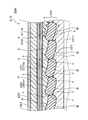
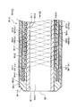
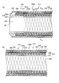
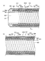
- FIG. 3 is an enlarged side sectional view of a part of the coil layer in FIG. 2. It is a sectional side view of the catheter front-end
- FIG. 4C is a side view showing a state where the slider is bent
- FIG. 4C is a side view showing a state where the tip is bent upward with a curvature larger than that of FIG.
- FIG. 6 is a side view showing a state where the tip is bent downward on the paper surface by operating (e), and a side view showing a state where the tip is bent downward with a larger curvature than (d) by operating the slider.
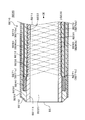
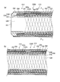
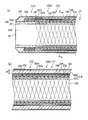
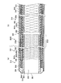
- FIG. 10 is an enlarged side sectional view of a part near the coil layer in FIG. 9. It is a sectional side view of the catheter front-end
- FIG. 5 is a side view showing a state where the slider is operated to bend the tip upward in the drawing
- (c) is a state where the slider is operated to bend the tip with a larger curvature than in FIG. It is a side view
- (d) is a side view which shows the state which operated the slider and bent the front-end
- the “longitudinal section of a medical device” refers to a cross section of a medical device (a catheter in each embodiment) cut through the central axis in parallel with the longitudinal direction.
- the “cross section of the medical device” refers to a cross section obtained by cutting the medical device parallel to the radial direction. The same applies to longitudinal sections of a tubular body, a coil layer, an inner layer and the like which are members of the catheter.
- the “cross-sectional shape in the longitudinal section” of the “coiled wire” refers to the cross-sectional shape of the wire in the longitudinal section of the medical device in a state where the wire is wound in a coil shape.
- a “wire” having a “non-circular cross-sectional shape” means that a long wire before being coiled is cut in the width direction of the wire (a direction orthogonal to the extending direction of the wire).
- the longitudinal direction means the longitudinal direction (longitudinal direction) of the medical device
- the radial direction means the thickness direction of the medical device.
- this may be abbreviate
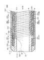
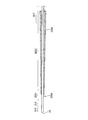
- FIG. 1 is a side sectional view of the distal end portion of the tubular main body 10 in the catheter 100 according to the first embodiment.
- the left side in FIG. 1 corresponds to the distal end side of the catheter, and the right side corresponds to the proximal side (proximal end side).
- the distal end of the catheter is also referred to as the distal end DE, and the proximal end is also referred to as the proximal end CE.
- the proximal end CE of the catheter 100 is not shown in FIG.
- FIG. 6 the whole figure and operation
- the catheter according to the present embodiment includes a long tubular body 10 having a main lumen 20 therein, as shown in FIG.
- the tubular body 10 includes an inner layer 11, a coil layer 30, a marker 40, an outer layer 12, a coat layer 50, and a sublumen 80.
- the inner layer 11 is a tubular layer that defines the main lumen 20 at the innermost periphery of the tubular body 10. That is, the inner layer 11 has a main lumen 20 inside.
- the coil layer 30 is disposed on the outer periphery of the inner layer 11.
- the marker 40 is attached in the vicinity of the distal end DE.
- the outer layer 12 is a layer that covers the entire outer periphery of the inner layer 11 including the coil layer 30 and the marker 40.
- the coat layer 50 is formed on the outer periphery of the outer layer 12.
- the sub-lumen 80 (first sub-lumen 80a, second sub-lumen 80b) is formed on the outer periphery of the main lumen 20, and the operation line 70 (first operation line 70a, second operation line 70b) is inserted therethrough.
- the tubular body 10 of the catheter 100 according to the present embodiment has an inner layer 11 formed of a resin material 111 and an outer layer 12 formed of a resin material 112 different from the inner layer 11. is doing.
- the tubular body 10 that is the body of the catheter 100 including the inner layer 11 and the outer layer 12 is called a sheath.
- the inner layer 11 or the outer layer 12 may be formed of one layer each, or may be formed as a multilayer structure formed of two or more kinds of different or similar materials.
- the coil layer 30 is formed by winding a single wire (one strip) 31 having a non-circular cross-sectional shape in the longitudinal direction (single strip winding).
- a wire 31 having a rectangular cross section is used.
- the coil layer 30 formed in this way has a radially outer side of the catheter 100 A and a radially inner side B of the cross-sectional shape of the wire 31 in the longitudinal section of the coil layer 30.
- the cross-sectional shape is also rectangular, and the outer side A and the inner side B are linear.
- the linear inner side B is inclined obliquely with respect to the longitudinal direction of the catheter 100.
- the width dimension corresponding to the major axis dimension is longer than the thickness dimension corresponding to the minor axis dimension.
- the ratio of the width dimension to the thickness dimension is preferably 1.1 or more, 5 or less, more preferably 1.5 or more and 4 or less, and further preferably 2 or more and 4 or less.
- the actual width of the wire 31 is 1 mm or less, preferably 0.5 mm.
- the cross-sectional shape of the wire 31 is not particularly limited as long as it is non-circular.
- non-circular oval, ellipse, semi-circle, fan shape (fan shape with one arc or ground paper shape with outer arc and inner arc), curved ball shape, polka dot shape or polygonal shape
- the polygon may be a convex polygon such as a rectangle, a trapezoid, a rhombus or a parallelogram, or a concave polygon having an internal angle exceeding 180 degrees.
- the non-circular shape may be a shape obtained by combining the above shapes, and specifically, may be a rounded polygon having a side protruding in an arc shape or a concave lens shape having a side recessed in an arc shape.
- the non-circular shape may have a long side and a short side having different lengths assuming a rectangle with a minimum area circumscribing the non-circular shape.
- the marker 40 is formed by attaching a ring member to the outer periphery of the inner layer 11 near the distal end DE.
- the marker 40 is made of a radiopaque material. Therefore, by confirming the position of the marker 40 by X-rays, it is possible to confirm to which position in the patient's body the catheter 100 has been inserted.
- a hydrophilic coat layer 50 having a lubrication treatment applied to the outer surface is provided as the outermost layer of the tubular body 10.
- the coat layer 50 may be provided arbitrarily. For example, if the outer layer 12 is excellent in lubricity and hydrophilicity, the coat layer 50 may not be provided.
- the sub-lumen 80 (first sub-lumen 80a, second sub-lumen 80b) through which the operation line 70 (first operation line 70a, second operation line 70b) is inserted is a tube member embedded in the outer layer 12. It is formed (see FIG. 1). Further, since the sub-lumen 80 is provided away from the main lumen 20 in the outer diameter direction, when the medicine or the like is supplied through the main lumen 20 or the optical system is inserted, they are leaked to the sub-lumen 80. You can avoid it. Then, by providing the sub-lumen 80 on the outer side of the coil layer 30 as in the present embodiment, the inner side of the coil layer 30, that is, the main lumen 20 is protected against the sliding operation line 70.
- the tip (distal end) 71 (71 a, 71 b) of the operation line 70 is connected to the marker 40.
- the present invention is not limited to this, and the operation line 70 may be fixed to a portion other than the marker 40, for example, the outer layer 12. Alternatively, the operation line 70 may be fixed by caulking the marker 40.
- a fluorine-based thermoplastic polymer As the material of the inner layer 11, for example, a fluorine-based thermoplastic polymer can be used. More specifically, a resin material 111 such as polytetrafluoroethylene (PTFE), polyvinylidene fluoride (PVDF), or perfluoroalkoxy fluororesin (PFA) can be used. As described above, by using the fluorine-based resin for the inner layer 11, the delivery property when supplying a contrast medium or a drug solution to the affected area through the main lumen 20 of the catheter 100 is improved.
- PTFE polytetrafluoroethylene
- PVDF polyvinylidene fluoride
- PFA perfluoroalkoxy fluororesin
- thermoplastic polymer As the material of the outer layer 12, for example, a thermoplastic polymer can be used. Examples include polyimide (PI), polyamideimide (PAI), polyethylene terephthalate (PET), polyethylene (PE), polyamide (PA), nylon elastomer, polyurethane (PU), ethylene-vinyl acetate resin (EVA), poly A resin material 112 such as vinyl chloride (PVC) or polypropylene (PP) can be used.
- PI polyimide
- PAI polyamideimide
- PET polyethylene terephthalate
- PE polyethylene
- PA polyamide
- nylon elastomer polyurethane
- PU ethylene-vinyl acetate resin
- PVC vinyl chloride
- PP polypropylene
- a flat wire made of a metal material is used as the material of the wire 31 of the coil layer 30.
- the present invention is not limited to this, and in the cross-sectional shape of the wire 31 in the longitudinal cross section of the coil layer 30, the inner side B when the inner side B of the wire 31 is linear is in the longitudinal direction.
- the maximum width direction of the cross-sectional shape is in the longitudinal direction. In contrast, it may be inclined so long as it is fitted into the inner layer 11 or the outer layer 12 and exhibits an anchor effect.
- Any material may be used for the wire 31.
- a metal material such as stainless steel (SUS), a nickel titanium alloy, steel, titanium, or a copper alloy, or a resin material can be used.
- the material of the marker 40 for example, an X-ray opaque material such as platinum can be used.
- the marker 40 of this embodiment is ring shape, it is not restricted to this, The other coil arrange
- a hydrophilic resin material 51 such as polyvinyl alcohol (PVA) or polyvinyl pyrrolidone can be used.
- the sub-lumen 80 is a hole formed along the main lumen 20.
- the holes formed through the outer layer 12 may be the sublumen 80, or a hollow tube may be inserted into the outer layer 12 and the lumen of the hollow tube may be the sublumen 80.
- a hollow tube (not shown in FIG. 1, see FIG. 3) made of a resin material that is harder and less tacky than the outer layer 12, such as PTFE or polyether ether ketone (PEEK), is used as the outer layer 12.
- the lumen is made into a sub-lumen 80.
- the operation line 70 As the material of the operation line 70, when extruding the sub-lumen 80 inserted through the operation line 70 together with the resin material 112 of the outer layer 12, the operation line 70 is required to have heat resistance equal to or higher than the melting temperature of the resin material 112.
- specific materials include, for example, PEEK, polyphenylene sulfide (PPS), polybutylene terephthalate (PBT), polymer fiber such as PI or PTFE, or stainless steel (SUS), Corrosion-resistant coated steel wires, metal wires such as titanium or titanium alloys can be used.
- the operation line 70 is not required to have heat resistance, such as when the operation line 70 is inserted into the sub-lumen 80 after the tubular body 10 is molded, in addition to the above materials, PVDF, high-density polyethylene (HDPE) ) Or polyester can also be used.
- the material for forming the catheter 100 can be appropriately selected in consideration of cost, ease of manufacture, purpose of use, and the like.
- the catheter 100 of this embodiment is configured by connecting an operation unit (not shown) to the proximal end of the tubular body 10 having the above-described configuration.
- the operation unit is connected to the proximal ends of the first and second operation lines 70a and 70b.
- the tubular body 10 of the catheter 100 can be freely bent in a desired direction from a linear shape. The operation procedure will be described in detail in a second embodiment described later.
- the bending of the catheter 100 means that the catheter 100 is deformed (bent) so that the central axis of the catheter 100 (for example, the central axis of the main lumen 20) is not a straight line (such as a curved line or a polygonal line). .
- the radius of the main lumen 20 can be about 200 ⁇ m to 300 ⁇ m.
- the inner layer 11 may have a thickness of about 10 ⁇ m to 30 ⁇ m
- the outer layer 12 may have a thickness of about 50 ⁇ m to 150 ⁇ m
- the outer diameter of the coil layer 30 may be 500 ⁇ m to 860 ⁇ m
- the inner diameter of the coil layer 30 may be 420 ⁇ m to 660 ⁇ m.
- the radius from the axial center (of the tubular body 10) of the catheter 100 to the center of the sublumen 80 can be about 300 ⁇ m to 450 ⁇ m
- the inner diameter of the sublumen 80 can be 40 ⁇ m to 100 ⁇ m.
- the thickness of the operation line 70 can be set to 30 ⁇ m to 60 ⁇ m.
- the outermost radius including the coat layer 50 from the axis of the catheter 100 (of the tubular body 10) can be about 350 ⁇ m to 490 ⁇ m.
- the outer diameter of the catheter 100 of this embodiment is less than 1 mm in diameter, and can be inserted into blood vessels such as the celiac artery.
- the catheter 100 of the present embodiment can enter the catheter 100 in a desired direction even in a branching blood vessel, for example.
- the manufacturing method of the catheter 100 of this embodiment forms the coil layer 30 by winding the wire 31 having a non-circular cross-sectional shape in a coil shape in the longitudinal direction (hereinafter referred to as “coil layer forming step”). ) At least.
- the method of manufacturing the catheter 100 includes, for example, a step of forming the inner layer 11 with the resin material 111 on the outer periphery of the core wire (hereinafter referred to as “inner layer forming step”), A coil layer forming step of forming the coil layer 30, a step of attaching the marker 40 to the outer periphery of the inner layer 11 in the vicinity of the distal end DE (hereinafter referred to as “marker mounting step”), and an outer layer made of the resin material 112. 12 and forming the tubular body 10 (hereinafter referred to as “outer layer forming step”).
- a step of forming the coat layer 50 around the outer layer 12 (hereinafter referred to as “coat layer forming step”) and a step of connecting an operation unit (not shown) (hereinafter referred to as “operation unit connection step”). And so on).
- the catheter 100 of this embodiment is manufactured by a manufacturing method including such steps. Hereinafter, each step will be described in detail.
- the inner layer 11 is formed by extruding or dispersion-molding the resin material 111 as described above onto a cylindrical mandrel (not shown) that is optionally mold-released on the surface as a core wire.
- the coil layer forming step the coil layer 30 is formed on the outer periphery of the inner layer 11 formed as described above. As this procedure, for example, the coil layer 30 is formed in advance, and at that time, in the cross-sectional shape of the wire 31 in the longitudinal section of the coil layer 30, the linear inner side B of the wire 31 extends in the longitudinal direction. Wind it so that it tilts diagonally.
- the coil layer 30 is disposed on the outer periphery of the inner layer 11, and in the outer layer forming step described later, when the heat shrinkage is caused by the heat shrinkable tube, the coil layer 30 is slightly shrunk by the compressive force, so that the wire 31 is 11 may be inserted.
- the non-circular wire 31 may be wound around the outer periphery of the inner layer 11 with a predetermined gap therebetween using a wire 31 winding device or the like.
- the linear inner side B of the wire 31 is inclined obliquely with respect to the longitudinal direction, and the wire 31 is formed on the inner layer 11.
- the wire 31 is wound so as to be fitted.
- the wire is wound so that the maximum width direction of the cross-sectional shape is inclined with respect to the longitudinal direction.
- the marker 40 made of the above-described material is caulked and fixed to the outer periphery of the inner layer 11 and closer to the distal end DE than the coil layer 30.
- the marker 40 is simply mounted on the outer periphery in the vicinity of the distal end DE of the inner layer 11, and the marker 40 is fixed by covering the marker 40 with the resin material 112 of the outer layer 12 in the next outer layer forming step. Also good.
- the outer layer 12 is formed on the entire outer periphery of the inner layer 11 including the coil layer 30 and the marker 40 using the resin material 112 as described above.
- the outer layer 12 may be formed by extruding the resin material 112 on the outer periphery of the inner layer 11.
- a tubular outer layer 12 having an inner diameter larger than the outer diameter of the inner layer 11 is formed in advance with the resin material 112, and the outer layer 12 is attached to the outer periphery of the inner layer 11.
- the inner layer 11 and the outer layer 12 may be brought into close contact with each other by attaching a heat shrinkable tube (not shown) to the outer periphery of the tube and heating the heat shrinkable tube to cause heat shrinkage.
- the heat shrink tube is removed.
- the outer layer 12 can be easily formed.
- the resin material 112 of the outer layer 12 melts and penetrates into the winding gap 32 of the wire 31 of the coil layer 30 and solidifies, thereby improving the adhesion between the inner layer 11 and the outer layer 12. Can be prevented.
- the inner layer forming step and the outer layer forming step are not limited to the above method, and any other method may be used.
- the sub-lumen 80 (first sub-lumen 80a, second sub-lumen 80b) made of a pipe member is extruded on the outer periphery of the coil layer 30 together with the resin material 112 of the outer layer 12 to form the outer layer.
- the sub-lumen 80 (80a, 80b) may be provided in 12.
- the operation line 70 (70a, 70b) may be inserted into the sub-lumen 80 (80a, 80b), and the tip 71 (71a, 71b) may be fixed to the marker 40, respectively.
- it may be extruded to the outer periphery of the coil layer 30 together with the outer layer 12 in a state where the operation line 70 is inserted into the sub-lumen 80.
- the mandrel is reduced in diameter by pulling both ends of the mandrel in opposite directions.
- the tubular body 10 including the main lumen 20, the inner layer 11, the outer layer 12, the coil layer 30, the marker 40, the coat layer 50, and the sublumen 80 through which the operation line 70 is inserted is obtained.
- the catheter 100 of this embodiment can be manufactured by assembling this tubular main body 10 and the operation part.
- the linear inner side B of the wire 31 is inclined obliquely with respect to the longitudinal direction. Therefore, the coil layer 30 can be fitted into the inner layer 11 and can also be fitted into the outer layer 12. Therefore, the adhesion of the inner layer 11, the coil layer 30, and the outer layer 12 can be improved by the anchor effect of the coil layer 30. As a result, even when a strong resistance force is applied when the catheter 100 is inserted into and extracted from the body cavity, it is possible to satisfactorily prevent the adhesion of each layer from being lowered and the interface peeling.
- the linear inner side B of the wire 31 is inclined obliquely with respect to the longitudinal direction.
- the inclination angle of the inner side B with respect to the longitudinal direction is greater than 0 degree and less than 45 degrees. Preferably they are 5 degree
- the layer thickness of the coil layer 30, that is, the distance between the innermost point and the outermost point of the wire 31 is smaller than the major axis dimension in the cross-sectional shape of the wire 31.
- the catheter 100 which has the outstanding flexibility which can maintain the lumen
- size can be obtained.
- the catheter 100 Via such a main lumen 20, it is possible to suitably carry out supply of medicines, insertion of optical systems, and the like. Further, since the predetermined gap 32 is interposed between the windings of the wire 31, the adjacent windings do not interfere with each other's operation. Therefore, the flexibility of the catheter 100 can be improved. Thus, in this embodiment, the catheter 100 having both excellent adhesion between layers and excellent flexibility due to kink resistance can be obtained.
- the cross-sectional shape of each winding of the wire 31 is such that the inner side B is linear, and the inner side B is inclined obliquely with respect to the longitudinal direction.
- the wire 31 is fitted into the inner layer 11 in a wedge shape, and a good anchor effect is exhibited.
- the adhesion between the inner layer 11 and the outer layer 12 in the gap 32 between adjacent wires 31 is also maintained. Therefore, the effect which prevents the interface peeling between the coil layer 30 and the inner layer 11 favorably also arises, and the catheter 100 excellent in durability and usability can be obtained.
- inner side B is linear is not only a straight line but also an error when forming wire 31 or a slight curve when coiled. Even if it does not reach the arc shape described later, it also includes a substantially straight line shape with some warping and distortion.
- the catheter 200 of the present embodiment has a coil layer 230 wound around a plurality of strips (four strips in the present embodiment), and the cross section of the wire 231 is oval, This is common with the catheter 100 according to the first embodiment. More specifically, the outer side A and the inner side B in the cross-sectional shape of the wire 231 are arcuate.
- the catheter 200 of this embodiment includes a tubular main body 210 and an operation unit 260.
- the operation part 260 is connected to the proximal end PE of the tubular body 210 and is a part for operating the operation line 270.
- the tubular body 210 includes an inner layer 211 made of a resin material 2111, a coil layer 230, an outer layer 212 made of a resin material 2112, a marker 240, a coat layer 250, and a sub-lumen 280 (first sub-lumen 280a and second sub-lumen 280b).
- the coil layer 230 of the present embodiment is formed by winding a wire 231 having both ends of a cross-sectional shape having an arc shape in multiple lines.
- the operation line 270 (the first operation line 270a and the second operation line 270b) is inserted through the sub-lumen 280.
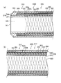
- FIG. 3 illustrates a longitudinal cross-sectional shape of the coiled wire 231, that is, the coil layer 230.
- the cross-sectional shape (not shown) obtained by cutting the wire 231 perpendicular to the extending direction is substantially the same as the vertical cross-sectional shape of the coil layer 230 shown in FIG. Both sides are semicircular and protrude outward, and the outer and inner sides (upper and lower sides) are linear. That is, the cross-sectional shape of the wire 231 is an oval.
- the wire 231 has an arcuate inner side B in the radial direction, and the maximum width direction (direction a or direction b in FIG. 3) is oblique with respect to the longitudinal direction of the catheter 200. Inclined.
- the wire 231 is disposed at the interface between the inner layer 211 and the outer layer 212 so as to be recessed into the inner layer 211 and the outer layer 212.
- the manufacturing method of the catheter of this embodiment is common to the manufacturing method of 1st embodiment except the point which winds the wire 231 many times.
- the wire 231 that starts winding first is defined as a first winding wire
- the wire 231 that starts winding thereafter is defined as a rear winding wire.
- a step of winding the post-wound wire in contact with the pre-winding wire and pressing the pre-winding wire toward the inner side of the winding diameter is performed. Therefore, as in the present embodiment, adjacent wires 231 come into contact with each other, and the leading wire is pressed inward by the trailing wire.
- the arc-shaped inner side B of the wire 231 in the longitudinal section of the catheter 200 has the entire coil layer 230 while the maximum width direction is inclined with respect to the longitudinal direction.
- the outer diameter at the maximum protruding position of the outer side A is the same diameter without being tapered or the like.
- the outer side A and the inner side B in the radial direction of the wire 231 are both convex shapes protruding inward in the radial direction. is there.
- the outer side A which is the ridge line on the outer diameter side and the inner side B which is the ridge line on the inner diameter side in the longitudinal cross-sectional shape of the wire 231 protrude toward the inner diameter side of the catheter 200, and conversely both width sides. It has a warped shape that goes to the outer diameter side.
- the outer side A and the inner side B are arcuate, and the longitudinal cross-sectional shape of the wire 231 is a bowed oval (curved ball shape).
- An orthogonal cross section (transverse cross section) shape with respect to the extending direction of the wire 231 is also a bowed oval warped shape.
- the cross-sectional shape of the wire 231 and the vertical cross-sectional shape of the coil layer 230 are not particularly distinguished, and are referred to as the cross-sectional shape of the wire 231.
- the outer width dimension a is shorter than the inner width dimension b (a ⁇ b).
- a method of making the wire 231 into such a bowed oval warped shape (i) a method of preparing a wire 231 previously formed in the shape and winding it in a coil shape, and (ii) a flat
- a method of applying stress to the wire 231 when winding the coil to deform the wire 231 into a bow or oval shape can be employed.
- a wire 231 having a flat cross-sectional shape is prepared.
- the coil 231 is formed by winding the wire 231 around the outer circumference of the inner layer 11 or another core wire, (ii-1) the center of the width of the wire 231 is pressed toward the inner diameter side, or (ii) -2) An external force is applied to at least one of the width sides of the wire 231 on the outer diameter side to deform the cross-sectional shape of the wire 231 into a bow or oval shape.
- the wire 231 may be deformed into a bow or oval by performing physical processing such as annealing.
- adjacent wires 231 are formed in close contact with each other. Furthermore, as shown in the enlarged sectional view of FIG. 3, both sides of the arcuate shape in the width direction of the cross section of the adjacent wire 231 are in point contact with each other. Further, the point y of the point contact between the wires 231 exists between the maximum protrusions x and x ′ of the arcs on both sides of the wire 231.
- one side edge in the width direction of the wire 231 of an arbitrary line is the adjacent edge of another adjacent line (see FIG.
- the cross-sectional shape of the wire 231 is deformed by the method (ii-2) described above. That is, by winding the multi-wire 231 so that the side edge of the post-winding wire overlaps the side edge of the pre-winding wire, stress is applied to the outer diameter side with respect to the side edge of the post-winding wire. And the cross-sectional shape of the wire is deformed into a bow or oval shape.
- the coil 200 is closely wound using the multiple wires 231, so that the catheter 200 has excellent rigidity. Therefore, the catheter 200 excellent in kink resistance can be obtained.
- the cross sections of the adjacent wires 231 of the coil layer 230 are in point contact (actually line contact). This point contact position y exists between the maximum protrusions x and x ′ of the arcs on both sides of the wire 231. Thereby, in the state where the arc-shaped adjacent edges of the adjacent strips overlap each other, the adjacent edges closely contact each other. For this reason, even if the adjacent wires 231 are relatively rotated and displaced, the close contact state can be maintained. As a result, the catheter 200 can be freely bent in a desired direction.
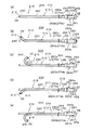
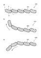
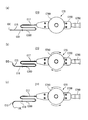
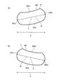
- FIG. 7 shows a conceptual diagram in which the wire 231 operates freely.
- FIG. 7A is a conceptual diagram showing a linear state before bending.
- FIG. 7B is a conceptual diagram showing a state where the coil layer 230 is bent upward in the drawing, and shows a state where the cross-sectional shape of the wire 231 is bent in the warping direction.
- FIG. 7C is a conceptual diagram showing a state where the coil layer 230 is bent downward in the drawing, and shows a state where the coil 231 is bent in a direction opposite to the warping direction of the cross-sectional shape of the wire 231.
- the adjacent windings of the wire 231 are in point contact with each other in the cross-sectional shape, they can be freely bent like a joint in the warping direction or in the opposite direction.
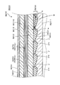
- FIG. 8 (a) a micrograph of the longitudinal section of the coil layer prepared by the method (ii-3) is shown.
- FIG. 4B is an enlarged photomicrograph of the part enclosed by the ellipse in FIG.
- the coil layer 230 is formed by closely winding four wires 231 having a non-circular cross-sectional shape into multiple lines, and the inner side B of the wire 231 in the longitudinal section is arcuate, The maximum width direction is inclined with respect to the longitudinal direction.
- adjacent wires 231 are in point contact with each other at position y, and this point contact position y exists between the maximum protrusions x and x ′ of the arcs on both sides of the wire 231. is doing.
- the side edges on both sides in the width direction of the longitudinal section are warped outwardly.
- the distal end 215 of the catheter 200 refers to a range of a predetermined length including the distal end DE of the catheter 200.
- the distal end DE of the catheter 200 is also the distal end of the tubular body 210.
- the proximal end portion 216 of the catheter 200 refers to a range of a predetermined length including the proximal end CE of the operation portion 260 of the catheter 200.
- the distal end of the tubular body 210 refers to a range of a predetermined length including the distal end DE
- the proximal end of the tubular body 210 includes the proximal end PE of the tubular body 10. A range of a predetermined length.
- the operation portion 260 connected to the proximal end portion 216 of the catheter 200 includes a shaft portion 261 extending in the longitudinal direction of the catheter 200, and the catheter 200 with respect to the shaft portion 261.
- Sliders 264 for example, first slider 264 a and second slider 264 b
- Sliders 264 that advance and retreat in the longitudinal direction
- a handle portion 262 that rotates integrally with the shaft portion 261
- a gripping portion 263 inserted so as to be rotatable around an axis.
- a proximal end portion PE of the tubular body 210 is fixed to the shaft portion 261.
- the distal end 215 of the catheter 200 can be bent by performing an operation of pulling a plurality of operation lines 270 individually or simultaneously on the slider 264 of the operation unit 260. It has become. Further, for example, the entire tubular body 210 is rotated together with the shaft portion 261 by rotating the handle portion 262 with respect to the grip portion 263 with the other hand while holding the grip portion 263 with one hand. Can be done.
- the sub-lumen 280 of the present embodiment is open at the proximal end PE of the tubular main body 210 as shown in each drawing of FIG. In addition, you may open in the distal side rather than the proximal end part PE of the tubular main body 210.
- FIG. The operation lines 270 are inserted into the respective sub-lumens 280, and the operation lines 270 are slidable with respect to the sub-lumen 280.
- the proximal end of the first operation line 270a is led out from the opening of the first sub-lumen 280a and connected to the first slider 264a of the operation unit 260.
- the proximal end of the second operation line 270b is led out from the opening of the second sub-lumen 280b and connected to the second slider 264b of the operation unit 260. Then, the first slider 264a and the second slider 264b are individually slid to the proximal side with respect to the shaft portion 261.
- the first operation line 270a or the second operation line 270b connected to each is pulled individually, and a tensile force is applied to the distal end portion 215 of the catheter 200 (that is, the distal end DE of the tubular body 210). It is done. As a result, the distal end 215 is bent toward the pulled operation line 270.
- the first slider 264a of the operation unit 260 is operated in the direction of pulling the proximal end of the first operation line 270a (that is, the right direction in FIG. 6). Then, a tensile force is applied to the distal end portion 215 of the catheter 200 via the operation line 270, and the distal end portion 215 bends toward the first sublumen 280a through which the first operation line 270a is inserted. .
- the first slider 264a of the operation unit 260 is operated in the direction in which the proximal end of the first operation line 270a is pushed into the catheter 200 (that is, the left direction in FIG. 6), the first operation line 270a There is virtually no pushing force on the distal end 215.
- the second slider 264b to which the second operation line 270b is fixed.
- the curvature of the distal end 215 can be changed according to the distance to be pulled. If the distal end 215 cannot be bent to a desired posture by merely pulling the operation lines 270 individually, the first and second operation lines 270a and 270b are simultaneously pulled to A desired posture of the end 215 may be realized.
- the distal end portion 215 is bent into various shapes, and the rotational phase of the tubular main body (sheath) 210 is adjusted by a rotation operation with respect to the handle portion 262.
- the bending amount and bending direction of the distal end portion 215 can be adjusted, and the catheter 200 can be freely entered into a body cavity that branches at various angles. Therefore, for example, the catheter 200 of the present embodiment can be advanced in a desired direction even for a branched blood vessel or a peripheral blood vessel.
- the bending angle of the distal end portion 215 preferably exceeds 90 degrees. Thereby, even if it is a case where the branch angle of a blood vessel is an acute angle which makes a U-turn, the catheter 200 can be made to approach this branch branch.
- the catheter 200 of this embodiment is inserted into a body cavity such as a blood vessel of a patient.
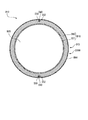
- the first sub-lumen 280a and the second sub-lumen 280b are formed to face each other by 180 degrees with the axis of the catheter 200 interposed therebetween.
- the first operation line 270a is inserted through the first sub-lumen 280a
- the second operation line 270b is inserted through the second sub-lumen 280b, so that the tip can be freely bent. Therefore, the catheter 200 can be actively inserted into the patient's body while operating the operation line 270 without requiring a guide wire or the like.
- the catheter 200 of the present embodiment when the first slider 264a of the operation unit 260 is operated and the first operation line 270a is pulled to the proximal side, as shown in FIG.
- the edge portion 215 bends upward in the drawing of FIG. Further, when this pulling amount is increased, the distal end portion 215 of the catheter 200 is bent with a large curvature above the plane of FIG. 6 as shown in FIG.
- the towing amounts may be different from each other.
- the curvature may be adjusted by pulling both the operation lines 270. More specifically, one of the operation lines 270 is pulled from a state where the distal end portion 215 is bent by pulling any one of the operation lines 270.
- an operation for reducing the bending amount of the distal end portion 215 and an operation for returning the posture of the distal end portion 215 from the bent state to the original linear posture can be performed. In this way, the bending amount can be finely adjusted by the operation of reducing the bending amount.
- the grasping portion 263 of the operation unit 260 is grasped with one hand, and the handle portion 262 is rotated with respect to the grasping portion 263 with the other hand.
- the entire catheter 200 is rotated together with the shaft portion 261 by a maximum of 90 degrees, the operator changes the bending direction of the distal end portion 215 of the catheter 200 to a desired direction, and the distal end DE is opposed to the affected part.
- the wire 231 is wound around the main lumen 220, the torsional rigidity of the tubular body 210 is increased.
- the torque transmission efficiency during the rotation operation of the catheter 200 is increased, and the rotation response of the distal end 215 to the rotation operation is improved. Furthermore, since the position of the tip can be clearly confirmed with the marker 240, the operation can be performed while easily confirming the current position and orientation of the distal end DE.
- the wire 231 is tightly wound around the main lumen 220 to form the coil layer 230 having more elastic force. Therefore, when the catheter 200 is bent by an operation on the operation line 270, an external force is applied to the coil layer 230 to bend its axial direction. However, the coil layer 230 tries to resist the external force by its elastic repulsive force. Therefore, the catheter 200 can be bent with a large curvature while suppressing a sharp bend. Therefore, since the sharp bending of the main lumen 220 is also suppressed and a good restoring force is obtained, the kink resistance is improved, and excellent flexibility is obtained. As a result, the lumen cross-sectional area of the main lumen 220 can be maintained at a sufficient size, so that it is possible to suitably supply a medicine or the like through the main lumen 220 or insert an optical system.
- the adjacent wires 231 of the coil layer 230 are in close contact with each other and are in point contact (line contact), they do not interfere with each other's operation and are excellent in flexibility.
- the coil layer 230 can be obtained. Even if the wire 231 is tightly wound, the coil layer 230 is formed so that the inner side B of the wire 231 has an arc shape and the maximum width direction of the cross-sectional shape is inclined with respect to the longitudinal direction. And the outer layer 212 are wedge-shaped and exhibit an anchor effect.
- the catheter 300 of the present embodiment has a coil layer 330 wound in multiple lines (four lines), and a part of adjacent wires 331 overlap each other and are in surface contact with each other.
- the configuration is substantially the same as that of the catheter 200 according to the second embodiment.
- the catheter 300 of the present embodiment includes an inner layer 311 made of a resin material 3111, a coil layer 330 formed by winding a wire 331 having arc-shaped ends at the cross section, and a resin material 3112.
- Sublayer 380 (first sublumen 380a, second sublumen 380b) through which the outer layer 312, the marker 340, the coat layer 350, and the operation lines 370 (first operation line 370a, second operation line 370b) are inserted. ), And an operation unit (not shown) connected to the proximal end CE of the tubular body 310.
- the outer side A and the inner side B of the wire 331 are arc-shaped, and the maximum width direction of the cross-sectional shape is inclined obliquely with respect to the longitudinal direction.
- each wire 331 is wound so as to be fitted into the inner layer 311 and the outer layer 312, it is possible to favorably prevent interfacial delamination between layers.
- the adjacent wires 231 of the coil layer 330 partially overlap each other and are in surface contact, the rigidity is further improved and the kink resistance is excellent.
- a set of four wires 331 is wound with a gap 332 interposed therebetween.
- the adhesion between the inner layer 311 and the outer layer 312 is increased, and the mutual interface peeling preventing effect can be further improved.
- the anchor effect of the coil layer 330 on the inner layer 311 and the outer layer 312 is somewhat from the coil layer 330 to the inner layer 311 side.
- the catheter 400 of this embodiment includes an inner layer 411 made of a resin material 4111, a coil layer 430 formed by winding a wire 431 having arc-shaped ends at both ends of a cross section, and a resin material 4112.
- Sub-lumen 480 (first sub-lumen 480a, second sub-lumen 480b) through which the outer layer 412, the marker 440, the coat layer 450, and the operation lines 470 (first operation line 470a, second operation line 470b) are inserted. ), And an operation unit (not shown) connected to the proximal end CE of the tubular body 410.
- the outer side A and the inner side B of the wire 431 are arc-shaped, and the maximum width direction of the cross-sectional shape is inclined obliquely with respect to the longitudinal direction.
- the resin material 4112 of the outer layer 412 penetrates into the winding gap 432 of the wire 431 and between the coil layer 430 and the inner layer 411, and the outer layer 412 and the inner layer 411 are in good contact.
- the wire 431 is wedged (embedded) in the outer layer 412 as a base layer. Due to these synergistic effects, excellent adhesion between layers can be obtained, and interfacial peeling can be satisfactorily prevented. Further, the coil layer 430 can provide the catheter 400 with excellent flexibility and kink resistance and excellent flexibility.
- the present invention is not limited to the above-described embodiment, and includes various modifications and improvements as long as the object of the present invention is achieved.
- a rough gap may be formed by winding a wire with a desired gap between adjacent windings.
- the tightly wound portion has a relatively large bending rigidity compared to the coarsely wound portion, so that it is maintained in a straight line when inserted into the body cavity, and can be easily inserted into the affected area. It becomes.
- the bending rigidity is relatively small in the rough winding portion, the flexibility is good and the bending is easy.
- this bent body can be held by having an appropriate rigidity. Therefore, in the rough winding portion, the bending operation of the distal end portion by the operation line can be easily performed.
- the catheter has two operation lines.
- three or more sublumens through which the operation lines are inserted may be formed on the tubular body.
- the bending operation of the catheter can be performed by pulling one or more of these operation lines.
- the distal end can be bent in any direction over 360 degrees by individually controlling the pulling lengths of three or more operation lines.
- the approach direction of the catheter can be operated only by pulling the operation line by the operation unit without applying a rotation operation to apply a rotational force to the entire catheter and direct the distal end portion in a predetermined direction.
- the distal end bending operation by pulling the operation line and the catheter rotation operation are used in combination.
- the distal end portion of the catheter can be bent in an arbitrary bending amount direction and an arbitrary direction.
- the sublumen may be disposed on the inner side of the coil layer, or may be bent using a guide wire or the like without providing the sublumen or the operation line.
- sublumen is formed of a pipe member, a long hole may be formed at the time of forming the outer layer to form sublumen, and an operation line may be inserted into the hole.
- a marker may be omitted if it is not necessary.
- the wire of the coil layer has a warped shape in which the cross-sectional shape in the longitudinal section of the catheter faces outward.
- the present invention is not limited to this, and may be inwardly warped, or may be linear without warping as in the first embodiment.
- the inner side when the inner side of the wire is linear is inclined obliquely with respect to the longitudinal direction
- the maximum width direction of the cross-sectional shape when the inner side of the wire is arc-shaped is inclined obliquely with respect to the longitudinal direction, so that not only has excellent flexibility and kink resistance, but also interfacial delamination between layers
- the product which was excellent also in the property prevention effect can be obtained.
- each of the above-described embodiments and modifications is performed on a catheter, but the present invention is not limited to the catheter, and is used by being inserted into a body cavity such as an endoscope or an ultrasonic instrument. It can also be applied to long medical devices.
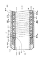
- FIG. 9 is a side sectional view of the distal end portion of the tubular main body B10 in the catheter B100 according to the fifth embodiment.
- the left side of FIG. 9 corresponds to the distal end side of the catheter, and the right side corresponds to the proximal side (proximal end side).
- the distal end of the catheter is also referred to as the distal end DE, and the proximal end is also referred to as the proximal end CE.
- the proximal end CE of the catheter B100 is not shown.
- FIG. 13 the whole figure and operation
- the catheter according to this embodiment includes a long tubular body B10 having a main lumen B20 therein as shown in FIG.
- the tubular body B10 includes an inner layer B11, a coil layer B30, a marker B40, an outer layer B12, a coat layer B50, and a sublumen B80.
- the inner layer B11 is a tubular layer that defines the main lumen B20 on the innermost periphery of the tubular body B10. That is, the inner layer B11 has a main lumen B20 inside.
- the coil layer B30 is disposed on the outer periphery of the inner layer B11.
- the marker B40 is attached in the vicinity of the distal end DE.
- the outer layer B12 is a layer that covers the entire outer periphery of the inner layer B11 including the coil layer B30 and the marker B40.
- the coat layer B50 is formed on the outer periphery of the outer layer B12.
- the sub-lumen B80 (first sub-lumen B80a, second sub-bloom B80b) is formed on the outer periphery of the main lumen B20, and the operation line B70 (first operation line B70a, second operation line B70b) is inserted therethrough.
- the tubular body B10 of the catheter B100 has an inner layer B11 formed of a resin material B111 and an outer layer B12 formed of a resin material B112 different from the inner layer B11. is doing.
- the tubular main body B10 that is the main body of the catheter B100 including the inner layer B11 and the outer layer B12 is called a sheath.
- the inner layer B11 or the outer layer B12 may be formed of one layer, or may be formed as a multilayer structure formed of two or more kinds of different or similar materials.
- the coil layer B30 has a plurality of (specifically, four) wires B31 each having a non-circular cross-sectional shape, which are closely wound in the longitudinal direction and wound in multiple strips (multiple winding). It is formed by doing. As shown in FIG. 9, in the coil layer B30 formed in this way, the outer side B32 corresponding to the outer diameter side of the catheter B100 is parallel to the longitudinal direction in the cross-sectional shape of the wire B31 in the longitudinal section of the coil layer B30. Yes, the inner side B33 corresponding to the inner diameter side is arcuate, and the center thickness direction of the cross-sectional shape is inclined obliquely with respect to the longitudinal direction.
- the central thickness direction of the cross-sectional shape of the wire B31 in the longitudinal section of the coil layer B30 is a straight line or a curved line drawn by continuously connecting the thickness centers (centers of the radial dimensions) in the individual cross-sectional shapes of the wire B31 in the longitudinal direction.
- the direction of the arrow W shown in FIG. 10 and FIG. 12 described later corresponds to the center thickness direction of the wire B31.
- the fact that the central thickness direction is inclined with respect to the longitudinal direction means that the central thickness direction includes both the longitudinal component and the radial component.
- the outer side B32 of the wire B31 is parallel to the longitudinal direction.
- the outer surface of the coil layer B30 is flat and has a smooth cylindrical shape.
- the coil layer B30 is disposed on the outer periphery of the inner layer B11 and is covered with the outer layer B12, so that the resin material B112 of the outer layer B12 is interposed between the coil layer B30 and the inner layer B11.
- the interface between the outer side B32 and the outer layer B12 of the wire B31 is peeled off, and relative movement in the longitudinal direction of both may be allowed.
- the inner side B33 inclined in the longitudinal direction is fitted into the resin material B112 of the outer layer B12 interposed between the inner layer B11 and the coil layer B30, so that the inner side B33 has an anchor effect on the outer layer B12. Play.
- the width dimension corresponding to the major axis dimension refers to the dimension in the center thickness direction of the wire B31.
- the width dimension of the wire B31 is longer than the thickness dimension corresponding to the minor axis dimension.
- the ratio of the width dimension to the thickness dimension ie, the width dimension when the thickness dimension is 1, is preferably 1.1 or more, 5 or less, more preferably 1.5 or more and 4 or less, and further preferably 2 or more and 4 or less.
- the actual width of the wire B31 is 1 mm or less, preferably 0.5 mm.
- the cross-sectional shape of the wire B31 of this embodiment is a partial oval shape obtained by cutting an oval shape at the outer side B32. Both sides in the width direction of the cross section of the wire B31 are arcuately projecting outward.
- the cross-sectional shape of the wire B31 is not particularly limited as long as it is a non-circular shape including the flat outer side B32.
- the outer side B32 being flat means that, in addition to the case where the outer side B32 is substantially linear, the curvature of the outer side B32 is significantly smaller than the other side.
- the side shape other than the outer side B32 may be an arc shape, may include a straight portion, or may include a corner portion.
- the cross-sectional shape of the wire B31 may be a curved shape including an arc portion such as a partial circle, a partial oval, or a partial ellipse, or a rectangle, a trapezoid, a rhombus, a parallelogram, a convex polygon, a concave polygon, or the like.
- the linear shape may be used. More specifically, a trapezoid, a triangle, or a pentagon obtained by cutting a square or a rectangle with a line segment may be used.
- This non-circular cross-sectional shape may have a long side and a short side having different lengths assuming a rectangle having a minimum area circumscribing the non-circular cross-sectional shape.
- the cross-sectional shape of the wire B31 and the vertical cross-sectional shape of the coil layer B30 are not particularly distinguished, and may be referred to as the cross-sectional shape of the wire B31.
- the outer surface has a flat cylindrical shape.
- the coil layer B30 in which the inner side B33 in the cross-sectional shape of each wire B31 is inclined with respect to the longitudinal direction can be obtained.
- the inner side B33 of the cross-sectional shape of each adjacent wire B31 is inclined obliquely in the same direction with respect to the longitudinal direction, and the thickness of the cross-sectional shape is inclined. It is gradually formed thicker in the direction.
- each winding of the wire B31 has a minimum thickness a on the distal end DE side in the cross-sectional shape, and gradually becomes thicker from the distal side to the proximal side, and the thickness b on the proximal end CE side is the maximum. It becomes.
- tilt angle of the said wire B31 of the inner side B33 is 45 degrees or less with respect to a longitudinal direction. By setting the inclination angle to 45 degrees or less, it is possible to satisfactorily fit into the outer layer B12 interposed between the inner layer B11 and the coil layer B30, and the rigidity of the catheter B100 can be increased without excessively high rigidity. Does not hinder flexibility and flexibility.
- the inner side B33 in the cross-sectional shape of the wire B31 is inclined about 20 degrees with respect to the longitudinal direction.
- the inclination angle of the wire B31 when the inner side B33 is arcuate as in the present embodiment refers to the central thickness direction of the wire B31 (arrow W in FIG. 10) and the longitudinal direction of the catheter B100 in the longitudinal section of the coil layer B30.
- the angle at which When the inner side B33 of the wire B31 is linear, the angle at which the inner side B33 and the longitudinal direction of the catheter B100 intersect is referred to as the inclination angle of the wire B31.
- adjacent wires B31 are in close contact with each other.
- arc-shaped ends are formed on both sides of the wire B31 in the width direction (that is, the distal side and the proximal side in the longitudinal direction).
- a part of the arc-shaped end portions overlap each other in the longitudinal direction by a distance c and are in surface contact.
- the position y of mutual surface contact on both sides of the wire B31 is located between the maximum protrusions x and x ′ of the arcs on both sides of the wire B31.
- the surface contact position y is a line segment region where adjacent wires B31 are in contact with each other in the longitudinal section of the coil layer B30.
- the position y of the surface contact is located between the maximum protrusions x and x ′ means that the maximum protrusions x and x ′ are located on both outer sides (on the end points of this line segment area). Is included).
- the coil layer B30 is closely wound using the multiple wires B31, and the arc-shaped ends of the wires B31 overlap each other. For this reason, when the adjacent wires B31 are relatively rotated and displaced and the coil layer B30 is bent, the wires B31 can be relatively moved while being kept in close contact with each other. Therefore, the catheter B100 can be freely bent in a desired direction with a desired curvature.
- the marker B40 is formed by attaching a ring member to the outer periphery near the distal end DE of the inner layer B11.
- the marker B40 is made of a radiopaque material. Therefore, by confirming the position of the marker B40 at the distal end DE by X-ray, it is possible to confirm to which position in the patient's body the catheter B100 has been inserted.
- a hydrophilic coat layer B50 having a lubrication treatment applied to the outer surface is provided as the outermost layer of the tubular body B10.
- the coat layer B50 may be provided arbitrarily. For example, if the outer layer B12 is excellent in lubricity and hydrophilicity, the coat layer B50 may not be provided.
- the sub-lumen B80 (first sub-bloom B80a, second sub-bloom B80b) through which the operation line B70 (first operation line B70a, second operation line B70b) is inserted is piped inside the outer layer B12 as shown in FIG. It is formed by embedding a member. Also. By providing the main lumen B20 apart from the outer diameter direction, it is possible to prevent these from leaking into the sub-lumen B80 when a medicine or the like is supplied through the main lumen B20 or an optical system is inserted. it can. Then, by providing the sub-lumen B80 outside the coil layer B30 as in the present embodiment, the inside of the coil layer B30, that is, the main lumen B20 is protected against the sliding operation line B70.
- the tip (distal end) B71 (B71a, B71b) of the operation line B70 is connected to the marker B40 as shown in FIG.
- the present invention is not limited to this, and the operation line B70 may be fixed to a portion other than the marker B40 at the distal end DE, for example, the outer layer B12, or the operation line B70 may be formed by caulking the marker B40. It may be fixed.
- the distal end B15 of the catheter B100 refers to a range of a predetermined length including the distal end DE (tip) of the catheter B100.
- the distal end DE of the catheter B100 is also the distal end of the tubular body B10.
- the proximal end B16 of the catheter B100 refers to a range of a predetermined length including the proximal end CE of the catheter B100.
- the distal end of the tubular body B10 refers to a range of a predetermined length including the distal end DE
- the proximal end of the tubular body B10 includes the proximal end PE of the tubular body B10.
- the operation part B60 is connected to the proximal end CE of the catheter B100 and has a shaft part B61 extending in the longitudinal direction and a slider that advances and retracts in the longitudinal direction with respect to the shaft part B61.
- B64 for example, the first slider B64a, the second slider B64b
- the handle portion B62 that rotates integrally with the shaft portion B61 and the shaft portion B61
- the proximal end portion of the tubular body B10 can rotate about the shaft.
- a gripping portion B63 inserted into the.
- the proximal end PE of the tubular body B10 is fixed to the shaft part B61.
- the catheter B100 By performing an operation of pulling two operation lines B70 (first operation line B70a and second operation line B70b) individually or simultaneously on the slider B64 of the operation unit B60, the catheter B100
- the distal end B15 can be bent. Further, for example, by rotating the handle portion B62 with respect to the gripping portion B63 with the other hand while holding the gripping portion B63 with one hand, the entire tubular body B10 is rotated together with the shaft portion B61. Can be done.
- the sub-lumen B80 of the present embodiment is open at the proximal end PE of the tubular main body B10 as shown in each drawing of FIG. In addition, you may open in the distal side rather than the proximal end part PE of tubular main body B10.
- the operation lines B70 are inserted into the sub-lumens B80, and the operation lines B70 are slidable with respect to the sub-blooms B80.
- the proximal end of the first operation line B70a is led out from the opening of the first sub-lumen B80a and is connected to the first slider B64a of the operation unit B60.
- the proximal end of the second operation line B70b is led out from the opening of the second sub-lumen B80b and is connected to the second slider B64b of the operation unit B60. Then, the first slider B64a and the second slider B64b are individually slid toward the base end side with respect to the shaft portion B61.
- the first operation line B70a or the second operation line B70b connected to each is pulled individually, and a tensile force is applied to the distal end B15 of the catheter B100 (that is, the distal end DE of the tubular body B10). It is done. As a result, the distal end B15 is bent toward the pulled operation line B70.
- a fluorine-based thermoplastic polymer As the material of the inner layer B11, for example, a fluorine-based thermoplastic polymer can be used. More specifically, a resin material B111 such as polytetrafluoroethylene (PTFE), polyvinylidene fluoride (PVDF), or perfluoroalkoxy fluororesin (PFA) can be used. As described above, by using a fluorine-based resin for the inner layer B11, the delivery property when supplying a contrast medium or a drug solution to the affected area through the main lumen B20 of the catheter B100 is improved.
- PTFE polytetrafluoroethylene
- PVDF polyvinylidene fluoride
- PFA perfluoroalkoxy fluororesin
- thermoplastic polymer examples include polyimide (PI), polyamideimide (PAI), polyethylene terephthalate (PET), polyethylene (PE), polyamide (PA), nylon elastomer, polyurethane (PU), ethylene-vinyl acetate resin (EVA), poly Resin material B112 such as vinyl chloride (PVC) or polypropylene (PP) can be used.
- PI polyimide
- PAI polyamideimide
- PET polyethylene terephthalate
- PE polyethylene
- PA polyamide
- EVA ethylene-vinyl acetate resin
- PVC vinyl chloride
- PP polypropylene
- the material of the wire B31 of the coil layer B30 it is preferable to use a flat wire made of a metal material, but the present invention is not limited to this, and any material may be used.
- a metal material such as stainless steel (SUS), a nickel titanium alloy, steel, titanium, or a copper alloy, or a resin material can be used.
- the material of the marker B40 for example, an X-ray opaque material such as platinum can be used.
- the marker B40 of this embodiment is ring shape, it is not restricted to this, The other coil arrange
- a hydrophilic resin material such as polyvinyl alcohol (PVA) or polyvinyl pyrrolidone can be used.
- Sublumen B80 is a hole formed along main lumen B20.
- a hole formed through the outer layer B12 may be a sub-lumen B80, or a hollow tube may be inserted into the outer layer B12 and a lumen of the hollow tube may be a sub-lumen B80.
- a hollow tube (see FIG. 10) made of a resin material that is harder and less tacky than the outer layer B12, such as PTFE or polyetheretherketone (PEEK), is inserted into the outer layer B12, and the lumen is It is named Subrumen B80.
- the operation line B70 As the material of the operation line B70, when the sub-lumen B80 inserted through the operation line B70 is extruded together with the resin material B112 of the outer layer B12, the operation line B70 is required to have heat resistance equal to or higher than the melting temperature of the resin material B112.
- the operation line B70 as specific materials, for example, polyether ether ketone (PEEK), polyphenylene sulfide (PPS), polybutylene terephthalate (PBT), polymer fiber such as PI or PTFE, or Metal wires such as stainless steel (SUS), steel wire coated with corrosion resistance, titanium or titanium alloy can be used.
- the operation line B70 is not required to have heat resistance, such as when the operation line B70 is inserted into the sub-lumen B80 after the tubular body B10 is formed, in addition to the above materials, PVDF, high density polyethylene (HDPE) ) Or polyester can also be used.
- the material for forming the catheter B100 can be appropriately selected in consideration of cost, ease of manufacture, purpose of use, and the like.
- the catheter B100 of this embodiment is configured by connecting an operation unit (not shown) to the proximal end (PE) of the tubular body B10 having the above-described configuration.
- the operation unit is connected to the proximal ends of the first and second operation lines B70a and B70b.
- the tubular body B10 of the catheter B100 can be freely bent in a desired direction from a linear shape.
- the operation procedure will be described in detail in a sixth embodiment to be described later.
- the bending of the catheter B100 means that the catheter B100 is deformed (bent) so that the central axis of the catheter B100 (for example, the central axis of the main lumen B20) is not a straight line (such as a curved line or a broken line). .
- the radius of the main lumen B20 can be about 200 ⁇ m to 300 ⁇ m.
- the thickness of the inner layer B11 can be about 10 ⁇ m to 30 ⁇ m, the thickness of the outer layer B12 can be about 50 ⁇ m to 150 ⁇ m, the outer diameter of the coil layer B30 can be 500 ⁇ m to 860 ⁇ m, and the inner diameter of the coil layer B30 can be 420 ⁇ m to 660 ⁇ m.
- the radius from the axis of the catheter B100 (in the tubular body B10) to the center of the sublumen B80 can be about 300 ⁇ m to 450 ⁇ m, and the inner diameter of the sublumen B80 can be 40 ⁇ m to 100 ⁇ m.
- the thickness of the operation line B70 can be 30 ⁇ m to 60 ⁇ m.
- the outermost radius including the coat layer B50 from the axial center of the catheter B100 (the tubular main body B10) can be about 350 ⁇ m to 490 ⁇ m.
- the outer diameter of the catheter B100 of this embodiment is less than 1 mm in diameter, and can be inserted into a blood vessel such as a celiac artery.
- the catheter B100 of the present embodiment can enter the catheter B100 in a desired direction even in a branching blood vessel, for example.
- a step of forming a coil layer B30 by winding a wire B31 having a non-circular cross-sectional shape in a coil shape in the longitudinal direction (hereinafter referred to as a “coil layer forming step”).
- the method for manufacturing the catheter B100 includes, for example, the step of forming the inner layer B11 with the resin material B111 on the outer periphery of the core wire (hereinafter referred to as “inner layer forming step”), and the outer surface of the inner layer B11 on the outer peripheral surface.
- a step of mounting the marker B40 (hereinafter referred to as “marker mounting step”), a step of forming the outer layer B12 from the resin material B112 and forming the tubular body B10 (hereinafter referred to as “outer layer forming step”), Have
- a step of forming a coat layer B50 around the outer layer B12 (hereinafter referred to as “coat layer forming step”) and a step of connecting the operation unit B60 (hereinafter referred to as “operation unit connection step”) And so on).
- the catheter B100 of this embodiment is manufactured by the manufacturing method including such steps.
- each step will be described in detail.
- the inner layer B11 is formed by extruding the resin material B111 as described above on a cylindrical mandrel (core wire) (not shown) that is optionally mold-released on the surface as a core wire, or by dispersion coating. To do.
- a method (individual creation method) in which the core wire covered with the inner layer B11 is loosely inserted inside the coil layer B30 can be employed.
- the individual creation method of (ii) is illustrated. Specifically, first, a plurality of wires B31 are wound around the surface of the coil core wire by using a winding machine. This coil core wire is separate from the core wire (mandrel) covered with the inner layer B11.
- the wire B31 may be set in the winding machine at an angle where the inner side B33 is inclined with respect to the longitudinal direction in the cross-sectional shape of the wire B31, and multiple windings may be performed.
- the coil layer B30 may be composed of a single multi-strand coil formed by a single winding process of the winding machine, or a plurality of multiple coils formed by a multiple winding process of the winding machine. You may comprise a strip coil by connecting with each other in the axial direction. Further, the coil layer B30 may be configured by arranging a plurality of multi-strip coils in an axial direction without being connected to each other.
- the coil layer B30 formed in this way is subjected to the above grinding process to smoothly process the outer surface of the coil layer B30.
- the grinding process will be described in detail later.
- the outer layer forming step the outer layer B12 is formed in the same layer as the coil layer B30 so as to include the surface of the coil layer B30 and the wire B31.
- a resin tube having an inner diameter larger than the surface of the coil layer B30 is formed in advance, and then the resin tube is mounted on the coil layer B30, and these are compressed by the compressive force resulting from the heat shrinkage of the heat shrinkable tube.
- the wire B31 may be fitted into the inner layer B11 by slightly contracting the coil layer B30 in the radial direction.
- the coil layer B30 is ground in advance, and is then attached to the inner layer B11 to be integrated. Thereby, the shavings generated in the grinding process and the grinding fluid used in the grinding process do not come into contact with the inner layer B11. Therefore, the inner layer B11 can be kept clean.
- the coil layer B30 is formed by spirally winding the wire B31, and then the grinding process is performed on the coil layer B30.
- the manufacturing method of the catheter B100 of the present invention is not limited thereto.
- a wire B31 having a non-circular cross section having a flat outer side B32 and an inclined inner side B33 as illustrated in FIG. 10 is prepared in advance, and the outer surface of the coil layer B30 is flattened using a winding device.
- the coil layer B30 may be formed by winding the wire B31 as described above.
- the wire B31 that starts winding first is referred to as a first winding wire
- the wire B31 that starts winding thereafter is referred to as a rear winding wire. It is good to wind while pressing against the wire.
- the wire B31 of the present embodiment has a warped shape in which the center of the width in the cross-sectional shape protrudes in the inner diameter direction and both sides of the width face outward after the coil layer forming step and before the grinding step ( Not shown). Therefore, after the grinding step, as shown in the enlarged views of FIGS. 9 and 10, the center of the width of the inner side B33 in the cross-sectional shape of the wire B31 protrudes in the inner diameter direction, and both sides of the width incline toward the outer side. It has a warped shape.
- the outer side B32 is flat.
- a method for forming such a warped shape (i) a method in which a wire B31 previously formed into the shape is prepared and wound into a coil shape, and (ii) coil winding around a flat wire B31.
- a method of applying stress sometimes and deforming it into a bow or oval can be typically employed.
- the outer side B32 of each wire B31 of the coil layer B30 is ground using a grinding device.
- the outer surface of the coil layer B30 may be ground and flattened using a coreless grinder (centerless grinder), or the coil core wire is inserted into the coil layer B30.
- the outer surface of the coil layer B30 may be ground and flattened by a cylindrical grinder while rotating the coil core wire.
- the outer side B32 of the wire B31 is ground in parallel to the longitudinal direction so that the outer appearance of the coil layer B30 is smooth and the outer diameter is within a predetermined length region. It is good to make it substantially the same.
- the coil layer B30 may be ground in a tapered shape so that the outer diameter gradually increases from the distal side to the proximal side in the longitudinal direction. Furthermore, in this embodiment, as shown in FIG. 10, it grinds so that the outer side B32 may be located outside in the radial direction from the mutual surface contact position y of the adjacent wire B31.
- the above-described marker B40 made of the material is mounted on the outer periphery of the inner layer B11 and closer to the distal end DE side than the coil layer B30.
- the time between the marker attaching step and the outer layer forming step is arbitrary, and the marker B40 attached to the distal end DE of the catheter B100 may be embedded in the outer layer B12, or the marker B40 may be placed on the surface of the outer layer B12. It may be attached by caulking.
- the outer layer B12 is formed on the entire outer periphery of the inner layer B11 including the coil layer B30 and the marker B40 using the resin material B112 as described above.
- the outer layer B12 may be formed by extruding the resin material B112 on the outer periphery of the inner layer B11.
- a tubular outer layer B12 having an inner diameter wider than the outer diameter of the inner layer B11 is previously formed of the resin material B112, and the outer layer B12 is attached to the outer periphery of the inner layer B11.
- the inner layer B11 and the outer layer B12 may be brought into close contact with each other by attaching a heat shrinkable tube (not shown) to the outer periphery of the tube and heating the heat shrinkable tube to cause heat shrinkage. Thereafter, the heat shrink tube is removed.
- a heat shrinkable tube (not shown)
- the outer layer B12 can be easily formed.
- the resin material B112 of the outer layer B12 melts and flows between the coil layer B30 and the inner layer B11 and solidifies, so that the inner layer B11 and the outer layer B12 are in good contact with each other, and the interfacial separation is good. Can be prevented.
- the inner side B33 of the wire B31 is arcuate, and the rear winding wire is wound by pressing the first winding wire inward in the inclination direction, so that the oblique inclination in the center thickness direction of the inner side B33 is maintained. Is done. Therefore, since the wire B31 of the coil layer B30 is well fitted into the resin material B112 of the outer layer B12 that has flowed and solidified between the coil layer B30 and the inner layer B11, and exerts an anchor effect, the action of a strong pulling force The adhesion between the coil layer B30 and the layer made of the resin material B112 of the outer layer B12 is improved.
- the inner layer forming step and the outer layer forming step are not limited to the above methods, and any other method may be used.
- the sub-lumen B80 (first sub-lumen B 80a and second sub-lumen B 80b) made of a tube member is extruded on the outer periphery of the coil layer B30 together with the resin material B112 of the outer layer B12 to form the outer layer.
- Sublumen B80 (B80a, B80b) may be provided in B12.
- the operation line B70 (B70a, B70b) may be inserted into the sub-lumen B80 (B80a, B80b), and the tip B71 (B71a, B71b) may be fixed to the marker B40.
- a tubular body B10 including a main lumen B20, an inner layer B11, an outer layer B12, a coil layer B30, a marker B40, a coat layer B50, and a sub-lumen B80 through which an operation line B70 is inserted is obtained.
- the catheter B100 of this embodiment can be manufactured by assembling this tubular main body B10 and the operation part B60.
- FIG. 14 shows a conceptual diagram in which the wire B31 operates freely.
- FIG. 14A is a conceptual diagram showing a linear state before bending.
- FIG. 14B is a conceptual diagram showing a state where the coil layer B30 is bent upward in the drawing, that is, a state where the outer surface is bent inward and the inner side is bent outward.
- FIG. 14C is a concept showing a state in which the coil layer B30 is bent downward in the drawing, that is, a state in which the outer surface is bent outward and the inner side is bent inward.
- the cross-sectional shape of the adjacent windings of the wire B31 since the cross-sectional shape of the adjacent windings of the wire B31 is in point contact, it can be freely bent like a joint in the outer direction or in the inner direction.
- FIG. 15 (a) a micrograph (image diagram) of a longitudinal section of a wire corresponding to the coil layer B30 is shown as a reference.
- the coil layer B30 has four wires B31 having a non-circular cross-sectional shape and densely wound in multiple strands.
- FIG. 15B is an enlarged view of FIG.
- the outer side B32 of the wire B31 in the longitudinal section is linear, but the inner side B33 is arcuate, and the central thickness direction of the cross-sectional shape of the inner side B33 is oblique with respect to the longitudinal direction (left-right direction in the figure). It is inclined.
- adjacent wires B31 are in point contact with each other at position y. This point contact position y is located between the maximum protrusions x and x ′ of the arcs on both sides of the wire B31.
- the catheter B100 of this embodiment is inserted into a body cavity such as a blood vessel of a patient.
- the first sub-lumen B80a and the second sub-lumen B80b are formed to face each other by 180 degrees with the axis of the catheter B100 interposed therebetween.
- the first operation line B70a is inserted through the first sub-lumen B80a
- the second operation line B70b is inserted through the second sub-lumen B80b, so that the tip can be freely bent. Therefore, the catheter B100 can be actively inserted into the patient's body while operating the operation line B70 without requiring a guide wire or the like.
- the catheter B100 of the present embodiment when the first slider B64a of the operation portion B60 is operated and the first operation line B70a is pulled proximally, as shown in FIG.
- the distal end B15 bends upward in the drawing of FIG. Further, when this pulling amount is increased, the distal end portion B15 of the catheter B100 is bent with a large curvature upward in the plane of FIG. 13 as shown in FIG.
- the distal end B15 of the catheter B100 is shown in FIG. Bends downward on the page. Further, when the pulling amount is increased, the distal end B15 of the catheter B100 is bent with a large curvature downward in the drawing of FIG. 13 as shown in FIG. 13 (e).
- the bending angle of the distal end B15 is preferably more than 90 degrees. Thereby, even if it is a case where the branch angle of the blood vessel is an acute angle that makes a U-turn, the catheter B100 can be made to enter the branch branch.
- the towing amounts may be different from each other. That is, when a desired curvature is not achieved even if any of the operation lines B70 is pulled individually, the curvature may be adjusted by pulling both the operation lines B70. More specifically, either one of the operation lines B70 is pulled from the state where the distal end B15 is bent by pulling any one of the operation lines B70. By this operation, an operation for reducing the bending amount of the distal end portion B15 and an operation for returning the posture of the distal end portion B15 from the bent state to the original linear posture can be performed. In this way, the bending amount can be finely adjusted by the operation of reducing the bending amount.
- the grip B63 of the operation unit B60 is gripped with one hand, and the handle B62 is rotated about the grip B63 with the other hand.
- the entire catheter B100 is rotated together with the shaft part B61 by a maximum of 90 degrees, the operator changes the bending direction of the distal end part B15 of the catheter B100 to a desired direction, and the distal end DE faces the affected part.
- the wire B31 is wound around the main lumen B20, the torsional rigidity of the tubular main body B10 is increased.
- the torque transmission efficiency during the rotation operation of the catheter B100 is increased, and the rotation response of the distal end portion B15 to the rotation operation is improved. Furthermore, since the tip position can be clearly confirmed with the marker B40, the operation can be performed while easily confirming the current position and orientation of the distal end DE.
- the wire B31 is tightly wound around the main lumen B20 to form a coil layer B30 having elasticity. Therefore, when the catheter B100 is bent by an operation on the operation line B70, an external force is applied to the coil layer B30 to bend its axial direction. However, the coil layer B30 tries to resist the external force by its elastic repulsive force. Therefore, the catheter B100 can be bent with a large curvature while suppressing a sharp bend. Therefore, the sharp bending of the main lumen B20 is also suppressed and a good restoring force can be obtained, so that the kink resistance is improved and excellent flexibility is obtained. As a result, the lumen cross-sectional area of the main lumen B20 can be maintained at a sufficient size, so that it is possible to suitably supply a medicine or the like through the main lumen B20 or insert an optical system.
- the cross-sectional shape of the wire B31 in the longitudinal section is inclined obliquely with respect to the longitudinal direction. Therefore, the inner side B33 of the wire B31 can be fitted into the base layer (outer layer B12) located on the inner diameter side. Therefore, the adhesion between the outer layer B12 and the coil layer B30 is improved by the anchor effect of the coil layer B30. For this reason, even if strong resistance force acts in the longitudinal direction when inserting and removing the catheter B100, it is possible to satisfactorily prevent a decrease in adhesion between the outer layer B12 and the coil layer B30 and interface peeling. On the other hand, since the outer surface of the coil layer B30 is smooth, the operation of the coil layer B30 in the longitudinal direction is not restricted by the outer layer B12.
- the coil layer B30 is flexibly bent. Therefore, when torque is applied to the proximal end CE of the catheter B100 inserted into the bent body cavity, the distal end DE of the catheter B100 rotates well. In other words, the rotational resistance when the catheter B100 is bent is reduced.
- the inner side B33 of the wire B31 is well anchored to the outer layer B12. Therefore, when the catheter B100 is removed from the body cavity, the wire B31 is restricted from moving relative to the outer layer B12 beyond the fine displacement. For this reason, even when the catheter B100 is removed from the bent body cavity, the outer layer B12 and the coil layer B30 are not separated.
- the catheter B200 of the present embodiment has a coil layer B230 fitted into the inner layer B211 and the outer surface is smoothly ground substantially flush with the surface of the inner layer B211. Except that the adjacent wires B231 are in point contact with each other and the outer surface of the coil layer B230 is in close contact with the outer layer B212, the catheter B100 according to the fifth embodiment has substantially the same configuration. As shown in FIGS.
- the catheter B200 of this embodiment includes an inner layer B211 made of a resin material B2111, a coil layer B230 in which both ends of an arc-shaped wire B231 are wound in multiple lines, and a resin material B2112.
- Sublayer B280 (first sublumen B280a, second sublumen B280b) through which the outer layer B212, the marker B240, the coat layer B250, and the operation line B270 (first operation line B270a, second operation line B270b) are inserted.
- an operation unit (not shown) that is connected to the proximal end PE of the tubular body B210 and operates the operation line B270.
- the outer appearance of the coil layer B230 is a cylindrical shape having substantially the same outer diameter and a smooth outer surface.
- the inner side B233 in the cross-sectional shape of the wire B231 is arcuate, and is wound so that the center thickness direction (arrow W in FIG. 12) is inclined with respect to the longitudinal direction and is fitted into the inner layer B211.
- the outer surface of coil layer B230 (outer side B232 of wire B231) is substantially flush with the outer peripheral surface of inner layer B211 and is point contact point y in the grinding step.
- the position y of point contact with each other on both sides of the wire B231 exists inside the winding diameter with respect to at least one of the maximum projecting portions x and x ′ of the arcs on both sides of the wire B231.
- 11 and 12 are cross-sectional views and are expressed as being in point contact, but actually, since point contact is continuous in the circumferential direction, adjacent wires B231 are mutually connected. Line contact.
- the coil layer B230 can be made thinner and the flexibility can be improved.
- the coil layer B230 can be easily fitted into the formed inner layer B211.
- the inner side B233 of the cross-sectional shape of the wire B231 in the longitudinal section of the coil layer B230 is inclined obliquely with respect to the longitudinal direction and is fitted in the inner layer B211 in a wedge shape to exert an anchor effect. Interfacial peeling with the inner layer B211 disposed on the surface can be prevented.
- the resin material B2111 of the inner layer B211 and the resin material B2112 of the outer layer B212 are in close contact with each other, and the coil layer B230 is fitted into the inner layer B211 so that the adhesiveness is high. Therefore, even if the mobility of the coil layer B230 with respect to the outer layer B212 is improved, it is possible to satisfactorily prevent the interfacial separation of each layer (the inner layer B211, the coil layer B230, and the outer layer B212).
- the adhesiveness between the coil layer B230 and the inner layer B211 arranged on the inner side thereof is maintained, and the cross-sectional area of the main lumen B220 is sufficiently secured, while having excellent flexibility and durability.
- a catheter B200 having excellent usability can be obtained.
- the present invention is not limited to the above-described embodiment, and includes various modifications and improvements as long as the object of the present invention is achieved.
- the coil layer is formed by multiple winding, but as another different modification, even if the coil layer is formed by winding one wire (single winding). Good. Also in this case, it may be wound so that the cross section in the longitudinal direction is in point contact, or may be wound so that adjacent wires are in close contact with each other. Even a catheter having such a coil layer can maintain the adhesiveness between the inner layer and the coil layer, ensure a sufficient cross-sectional area of the main lumen, and have excellent flexibility.
- the catheter has two operation lines.
- three or more sublumens through which the operation lines are inserted may be formed on the tubular body.
- the bending operation of the catheter can be performed by pulling one or more of these operation lines.
- the distal end can be bent in any direction over 360 degrees by individually controlling the pulling lengths of three or more operation lines.
- the approach direction of the catheter can be operated only by pulling the operation line by the operation unit without applying a rotation operation to apply a rotational force to the entire catheter and direct the distal end portion in a predetermined direction.
- the distal end bending operation by pulling the operation line and the catheter rotation operation are used in combination.
- the distal end portion of the catheter can be bent in an arbitrary bending amount direction and an arbitrary direction.
- the sublumen may be disposed on the inner side of the coil layer, or may be bent using a guide wire or the like without providing the sublumen or the operation line.
- sublumen is formed of a pipe member, a long hole may be formed at the time of forming the outer layer to form sublumen, and an operation line may be inserted into the hole.
- a marker may be omitted if it is not necessary.
- the wire of the coil layer before grinding has a warped shape in which both sides in the width direction in the cross-sectional shape in the longitudinal direction are directed outward. Therefore, after grinding, the inner side has an arc shape bulging inward in the radial direction.
- the present invention is not limited to this, and may have a warped shape that faces inward on both sides, and may have an arc shape in which the inner side after grinding bulges outward in the radial direction. It may be linear without being. In any case, it is possible to obtain a catheter that is excellent in flexibility while maintaining excellent adhesion between the inner layer and the coil layer and sufficiently securing the cross-sectional area of the main lumen.
- the outer surface of the coil layer is ground in parallel with the longitudinal direction of the catheter, and the appearance is cylindrical.
- the present invention is not limited to this, and as long as the coil layer can be freely moved in the longitudinal direction, the coil layer may be slanted in the longitudinal direction and ground to have a tapered shape.
- the taper may be a taper having a large diameter on the distal end DE side and gradually decreasing in the proximal end CE direction, or a small diameter on the distal end DE side and gradually increasing in the proximal end CE direction. It may be a taper.
- you may combine a taper shape and a cylindrical shape.
- the outer surface of the catheter bend portion that is, the coil layer portion near the distal end is ground to smooth the outer surface
- the non-bent portion that is, the vicinity of the proximal end, does not grind the outer surface of the coil layer.
- the distal end has excellent flexibility without being restricted by the outer layer, and the outer surface near the proximal end can be fitted into the outer layer to improve adhesion. .
- both the distal end and the proximal end are excellent in rigidity, unexpected kinking due to a pushing force or the like is prevented, and the catheter can be smoothly advanced to the affected area.
- each of the above-described embodiments and modifications is performed on a catheter, but the present invention is not limited to the catheter, and is used by being inserted into a body cavity such as an endoscope or an ultrasonic instrument. It can also be applied to long medical devices.
- FIG. 16 is a schematic longitudinal sectional view of a medical device main body C300 of a catheter C10 as a preferred example of a medical device according to the seventh embodiment.
- Fig.16 (a) shows a front-end
- the left side of FIG. 16 corresponds to the distal end side of the catheter, and the right side corresponds to the proximal side (proximal end side).
- FIG. 17 is a schematic diagram showing an example of the cross-sectional shape and posture (inclined or non-inclined) of the wire C52. Of these, FIG.
- FIG. 17 (a) shows the cross-sectional shape and posture at the distal end C15. ) Shows the cross-sectional shape and posture at the intermediate portion C18, respectively.
- 18 is a cross-sectional view taken along the line AA in FIG. In FIG. 18, the wire coil C50 is not shown.
- FIG. 19 is a schematic plan view of the catheter. 19A shows a state where the distal end portion of the medical device main body C300 is not bent, and FIG. 19B shows an operation where the distal end portion of the medical device main body C300 is bent in one direction.
- FIG. 19C shows a state where an operation of bending the distal end portion of the medical device main body C300 in the opposite direction is performed.
- the medical device for example, catheter C10
- the medical device has a long and flexible medical device body C300 that is inserted into a body cavity.
- the medical device body C300 is formed by winding a long resin tube (sheath C16) and a wire C52 having a non-circular cross-sectional shape in a spiral shape, and is embedded in the resin tube coaxially with the resin tube.
- a coil C50 In the longitudinal section of the wire C52, assuming that the thickness of the wire C52 is T and the maximum height difference from the axial center of the medical device body C300 to the outer surface C52a of the wire is H, the value of H / T is the length of the medical device body C300. It depends on the position in the direction. Details will be described below.
- the catheter C10 has a medical device main body C300 and an operation mechanism for performing a bending operation of the distal end portion of the medical device main body C300.
- the operation mechanism includes an operation line C40 (FIGS. 16 and 18) and an operation unit C70 for performing an operation of pulling the operation line C40.
- the operation line C40 is embedded in the medical device main body C300 along the longitudinal direction of the medical device main body C300.
- the operation unit C70 is provided at the proximal end portion of the medical device main body C300.
- the operation portion C70 is connected to the proximal end portion of the operation line C40, and the distal end portion of the medical device main body C300 can be bent by operating the operation portion C70.
- the medical device main body C300 as the main body of the catheter C10 is long and flexible, and is used by being inserted into a body cavity.
- Catheter C10 is an example that is preferably an intravascular catheter that is used by being inserted into a blood vessel. More specifically, it is a preferable example that the medical device main body C300 of the catheter C10 is formed to a size that allows the medical device main body C300 to enter any of the eight sub-regions of the liver. .
- the predetermined length region including the distal end (tip) DE of the catheter C10 (and the medical device main body C300) is referred to as the distal end C15 of the catheter C10 (and the medical device main body C300). That's it.
- the predetermined length region including the proximal end (proximal end) (not shown) of the catheter C10 (and the medical device main body C300) is referred to as the proximal end portion (as well as the catheter C10 (and the medical device main body C300)). It is referred to as a proximal end portion C17 (FIG. 19).
- a predetermined length region adjacent to the proximal end side of the distal end portion C15 in the longitudinal direction of the catheter C10 (and the medical device main body C300) is referred to as an intermediate portion C18.
- the intermediate part C18 is located on the distal end side with respect to the proximal end part C17.
- a main lumen C20 and a sub-lumen C30 are formed inside the medical device main body C300.
- the main lumen C20 and the sublumen C30 extend along the longitudinal direction (the left-right direction in FIG. 16) of the medical device main body C300 (the catheter C10).
- the main lumen C20 is disposed at the center of the cross section (cross section orthogonal to the longitudinal direction) of the medical device main body C300
- the sublumen C30 is disposed around the main lumen C20. More specifically, for example, in the cross section, the sub-lumens C30 are arranged at rotationally symmetric positions with respect to the center of the main lumen C20.
- the catheter C10 has, for example, a plurality of sublumens C30. Each sub-lumen C30 has a smaller diameter than the main lumen C20.
- the sub-lumen C30 and the main lumen C20 and the sub-lumen C30 are arranged separately from each other.
- the plurality of sub-lumen C30 are distributed around the main lumen C20.
- the number of sub-lumen C30 is two, and the sub-lumen C30 is arranged around the main lumen C20 at intervals of 180 degrees.
- the operation lines C40 are respectively inserted into the sub-lumens C30. That is, the catheter C10 has, for example, two operation lines C40.
- the operation line C40 is movable relative to the sub-lumen C30 in the longitudinal direction of the sub-lumen C30 by sliding with respect to the peripheral wall of the sub-lumen C30. That is, the operation line C40 is slidable in the longitudinal direction of the sub-lumen C30.
- the operation line C40 may be formed of a single wire, but may be a stranded wire formed by twisting a plurality of thin wires.
- the number of fine wires constituting one stranded wire is not particularly limited, but is preferably 3 or more.
- a suitable example of the number of thin wires is three or seven.
- the number of thin lines constituting the operation line C40 is three, the three thin lines are arranged point-symmetrically in the cross section.
- the number of fine lines constituting the operation line C40 is seven, the seven fine lines are arranged in a honeycomb in a point-symmetric manner in the cross section.
- the outer dimension of the operation line C40 (diameter of the circumscribed circle of the stranded wire) can be, for example, 25 to 55 ⁇ m.
- the material of the wire constituting the operation wire C40 (or the fine wire constituting the stranded wire)
- Poly paraphenylene benzobisoxazole
- PEEK polyether ether ketone
- PPS polyphenylene sulfide
- PBT polybutylene terephthalate
- PI polyimide
- PTFE polytetrafluoroethylene
- Polymer fibers can be used.
- a hollow tube C32 formed in advance is embedded in an outer layer C60 (described later) along the longitudinal direction of the medical device main body C300, and the hollow tube
- the lumen of C32 is called subrumen C30. That is, in these examples, the sublumen C30 is configured by the lumen of the hollow tube C32 embedded in the medical device main body C300.
- the hollow tube C32 can be made of, for example, a thermoplastic resin.
- thermoplastic resin include low friction resins such as polytetrafluoroethylene (PTFE) and polyetheretherketone (PEEK).
- the sub-lumen C30 is formed by forming a long hollow along the longitudinal direction of the medical device main body C300 in the outer layer C60 (described later).
- the medical device main body C300 includes a sheath C16 configured to include, for example, an inner layer C21, an outer layer C60 formed by laminating around the inner layer C21, and a coat layer C64 formed around the outer layer C60.
- the sheath C16 is made of, for example, a resin material. That is, the sheath C16 includes an outer layer C60 and an inner layer C21 each made of a resin material.
- the sheath C16 is a hollow resin layer, that is, a resin tube including the outer layer C60 and the inner layer C21. This resin tube is disposed coaxially with the wire coil C50 (described later) and covers the wire coil C50. The resin tube is attached to the wire coil C50.
- the inner layer C21 is made of a tubular resin material.
- a main lumen C20 is formed at the center of the inner layer C21.
- the outer layer C60 is made of the same or different resin material as the inner layer C21.
- the sublumen C30 is formed inside the outer layer C60.
- the material of the inner layer C21 examples include a fluorine-based thermoplastic polymer material.
- the fluorine-based thermoplastic polymer material is, for example, polytetrafluoroethylene (PTFE), polyvinylidene fluoride (PVDF), or perfluoroalkoxy fluororesin (PFA).
- PTFE polytetrafluoroethylene
- PVDF polyvinylidene fluoride
- PFA perfluoroalkoxy fluororesin
- the material of the outer layer C60 is, for example, a thermoplastic polymer.
- a thermoplastic polymer polyimide (PI), polyamideimide (PAI), polyethylene terephthalate (PET), polyethylene (PE), polyamide (PA), nylon elastomer, polyurethane (PU), ethylene-vinyl acetate resin (EVA) And polyvinyl chloride (PVC) or polypropylene (PP).
- the resin material constituting the sheath C16 may contain an inorganic filler.
- an inorganic filler for example, as the resin material constituting the outer layer C60 occupying most of the thickness of the sheath C16, a material containing an inorganic filler can be used.
- the inorganic filler is, for example, barium sulfate or bismuth carbonate.
- the coat layer C64 constitutes the outermost layer of the medical device main body C300 and is made of a hydrophilic material.
- the coat layer C64 may be formed only in a region extending over a part of the distal end portion C15 of the medical device main body C300, or may be formed over the entire length of the medical device main body C300.
- the coat layer C64 is made hydrophilic by molding it with a hydrophilic resin material such as polyvinyl alcohol (PVA) or polyvinylpyrrolidone.
- PVA polyvinyl alcohol
- the coat layer C64 may be formed by subjecting the outer surface of the outer layer C60 to lubrication so that at least the outer surface of the outer layer C60 is hydrophilic.
- the catheter C10 further includes a wire coil C50 wound around the inner layer C21.
- the wire coil C50 is configured by, for example, winding one or a plurality of wires (wires) C52 formed of an elastic body in a spiral shape.
- a material of the wire C52 constituting the wire coil C50 for example, it is preferable to use a metal.
- the material is not limited to this example, and any material having higher rigidity and elasticity than the inner layer C21 and the outer layer C60 may be used. Other materials (for example, resin) may be used.
- the metal material of the wire C52 for example, stainless steel (SUS), nickel titanium alloy, steel, titanium, or copper alloy can be used. An example of the cross-sectional shape of the wire C52 will be described later.
- the wire coil C50 is included in the outer layer C60. In the present embodiment, the sub-lumen C30 is formed outside the wire coil C50 inside the outer layer C60.
- the radius of the main lumen C20 is about 200 to 300 ⁇ m
- the thickness of the inner layer C21 is about 10 to 30 ⁇ m
- the thickness of the outer layer C60 is about 50 to 150 ⁇ m
- the outer diameter of the wire coil C50 is 500 to 860 ⁇ m in diameter
- the inner diameter of the wire coil C50 Can have a diameter of 420 to 660 ⁇ m.
- the radius (distance) from the axis of the medical device main body C300 to the center of the sublumen C30 is about 300 to 450 ⁇ m
- the inner diameter (diameter) of the sublumen C30 is 40 to 100 ⁇ m.
- the thickness of the operation line C40 is about 30 to 60 ⁇ m.
- the outermost diameter (radius) of the medical device main body C300 is about 350 to 490 ⁇ m, that is, the outer diameter is less than 1 mm in diameter.
- the distal end C15 of the medical device main body C300 is provided with a ring-shaped marker C66 made of a material that does not transmit radiation such as X-rays.
- the marker C66 is made of a metal material such as platinum.
- the marker C66 is provided, for example, around the main lumen C20 and inside the outer layer C60.
- the tip C41 of the operation line C40 is fixed to the distal end C15 of the medical device main body C300.
- a mode in which the tip C41 of the operation line C40 is fixed to the distal end C15 is not particularly limited.
- the tip C41 of the operation line C40 may be welded or fastened to the marker C66, may be welded to the distal end C15 of the medical device main body C300, or the marker C66 or the medical device main body C300 may be bonded with an adhesive.
- the distal end C15 may be adhesively fixed.
- the sublumen C30 is open at least on the proximal end C17 side of the catheter C10.
- the base end part of each operation line C40 protrudes from the opening of the sub-lumen C30 to the proximal end side.
- the base end part of each operation line C40 is connected to the operation part C70 provided in the proximal end part C17 of the medical device main body C300.
- the operation unit C70 includes, for example, a main body case C700 and a wheel operation unit C760 provided to be rotatable with respect to the main body case C700.
- the proximal end portion of the medical device main body C300 is introduced into the main body case C700.
- a hub C790 is attached to the rear end portion of the main body case C700.
- the base end of the sheath C16 is fixed to the front end portion of the hub C790.
- the hub C790 is a cylindrical body in which a hollow that penetrates the hub C790 forward and backward is formed.
- the hollow of the hub C790 communicates with the main lumen C20 of the medical device main body C300.
- An injector (syringe) (not shown) can be inserted into the hub C790 from behind.
- a liquid such as a chemical solution
- the liquid is supplied to the distal end of the medical device main body C300 via the main lumen C20, and the liquid is supplied from the distal end of the medical device main body C300 to the patient. It can be supplied into a body cavity.
- the operation line C40 and the hollow tube C32 are branched from the sheath C16 at the front end portion of the main body case C700.
- the proximal end portion of the hollow tube C32 is open, and the proximal end portion of the operation line C40 protrudes from the opening of the proximal end portion of the hollow tube C32 to the proximal end side.
- each operation line C40 is directly or indirectly connected to the wheel operation portion C760.
- the operation line C40 can be individually pulled to the proximal end side, and the distal end C15 of the medical device main body C300 can be bent. Yes.
- the bending of the medical device main body C300 includes a mode in which the medical device main body C300 bends in a “ku” shape and a mode in which the medical device main body C300 is bent like a bow.
- the distal end C15 of the medical device main body C300 is moved in the first direction and vice versa.
- the second direction which is the direction, can be bent.
- the first direction and the second direction are included in the same plane.
- the medical device main body C300 of the catheter C10 of the present embodiment can be made to enter a body cavity such as a branched blood vessel in a desired direction. That is, the approach direction to the body cavity can be changed by performing an operation of bending the distal end portion C15.
- the wire C52 constituting the wire coil C50 has a non-circular cross-sectional shape.
- the wire C52 is a so-called flat line having a rectangular shape with a flat cross-sectional shape, for example.
- the width dimension corresponding to the major axis dimension is longer than the thickness dimension corresponding to the minor axis dimension.
- the ratio of the width dimension to the thickness dimension, ie, the width dimension when the thickness dimension is 1, is preferably 1.1 or more, 5 or less, more preferably 1.5 or more and 4 or less, and further preferably 2 or more and 4 or less.
- the actual width of the wire C52 is 1 mm or less, preferably 0.5 mm.
- the wire C52 is wound such that the cross-sectional shape of the wire C52 in the longitudinal cross section of the medical device main body C300 is thinner than the width.
- the wire C52 when the wire C52 is wound in a spiral shape with an appropriate tension and at an appropriate angle, the wire C52 is bent in a transverse sectional shape and a longitudinal sectional shape, for example, as shown in FIG.
- the concave shape as shown in FIG. this shape will be described in more detail.
- the outer surface C52a is a concave curved surface
- the inner surface C52b is a convex curved surface.
- the end surfaces C52c and C52d on the distal end side and the proximal end side are convex curved surfaces that protrude toward the distal end side and the proximal end side, respectively.
- the wire C52 is inclined with respect to the longitudinal direction of the medical device main body C300. That is, as shown in FIG. 17A, in the longitudinal section of the wire C52, the maximum width direction W in the sectional shape of the wire C52 is inclined with respect to the longitudinal direction X of the medical device main body C300.
- the inclination angle of the maximum width direction W with respect to the longitudinal direction X is greater than 0 degree and less than 45 degrees. Preferably they are 5 degree
- the outer surface C52a and the inner surface C52b of the wire C52 are also inclined with respect to the longitudinal direction X.
- Examples of a method for winding the wire C52 so that the maximum width direction W is inclined with respect to the longitudinal direction X include the following methods. (1) Method of winding wire C52 while twisting wire C52 so that wire C52 is deformed around the axis of wire C52 in a direction inclined with respect to longitudinal direction X. As an example of this method, wire C52 is plastically deformed. Thus, a method of winding the wire C52 by twisting it can be mentioned. Another example of this method is a method in which the wire C52 is wound while being twisted so that the wire C52 is elastically deformed, and then the shape of the wire C52 is stabilized by the heat treatment by the heat treatment. .
- the wire C52 is connected to the medical device main body C300. It is parallel to the longitudinal direction. That is, as shown in FIG. 17B, in the longitudinal section of the wire C52, the maximum width direction W in the sectional shape of the wire C52 is parallel to the longitudinal direction X of the medical device main body C300.
- the thickness of the wire C52 is T
- the maximum height difference from the axial center of the medical device main body C300 to the outer surface C52a of the wire C52 is H.
- the maximum height difference H means a difference between the longest and shortest distances from the axis of the medical device main body C300 to the outer surface C52a.
- the value of H / T varies depending on the position in the longitudinal direction of the medical device main body C300. That is, in the present embodiment, the H / T value at the distal end C15 of the medical device main body C300 is larger than the H / T value at the intermediate portion C18 of the medical device main body C300.
- the anchor effect of the wire C52 with respect to the sheath C16 and the anchor effect per unit thickness of the wire C52 (hereinafter referred to as the shape factor unit anchor effect) is the medical device body C300. It depends on the position in the longitudinal direction. That is, in this embodiment, the shape factor unit anchor effect at the distal end C15 of the medical device main body C300 is larger than the shape factor unit anchor effect at the intermediate portion C18 of the medical device main body C300.
- the shape factor means a factor including the shape and posture of the wire C52 (inclination with respect to the sheath C16).
- the shape factor unit anchor effect is increased due to the shape or posture of the wire C52 compared to the case where the wire C52 has a shape such as a rectangular cross section and is not inclined with respect to the longitudinal direction of the medical device main body C300.
- This is an anchor effect for relative movement in the longitudinal direction of the medical device main body C300 between the wire C52 and the sheath C16 per unit thickness of C52.
- the higher the anchor effect the better the peeling between the wire coil C50 and the sheath C16 (especially the outer layer C60) can be suppressed when the medical device body C300 is removed from the body cavity.
- the value of H differs depending on the position in the longitudinal direction of the medical device main body C300. That is, in this case, the value of H at the distal end C15 of the medical device main body C300 is larger than the value of H at the intermediate portion C18 of the medical device main body C300.
- the anchor effect of the wire C52 on the sheath C16 of the shape factor of the wire C52 (hereinafter referred to as the shape factor anchor effect) varies depending on the position in the longitudinal direction of the medical device main body C300.
- the shape factor anchor effect at the distal end C15 of the medical device main body C300 is larger than the shape factor anchor effect at the intermediate portion C18 of the medical device main body C300.
- the shape factor anchor effect is increased due to the shape or posture of the wire C52 compared to the case where the wire C52 has a shape such as a rectangular cross section and is not inclined with respect to the longitudinal direction of the medical device main body C300. It is an anchor effect with respect to relative movement in the longitudinal direction of the medical device main body C300 between the sheath C16 and the sheath C16.
- the top P located farthest from the heart is displaced from the center position C of the wire C52 in the longitudinal direction of the medical device main body C300.
- the wire C52 is inclined at the distal end portion C15, as shown in FIG. 17A, the top portion P is based on the center position C of the wire C52 in the longitudinal direction of the medical device main body C300. It exists only on one side.
- the mutually adjacent winding parts of the wire coil C50 have mutually overlapped in the longitudinal direction of the medical device main body C300.
- the winding portions adjacent to each other of the wire coil C50 do not overlap each other.
- the value of H / T and the value of H at the distal end C15 are larger than the value of H / T and the value of H at the intermediate part C18. That is, in a partial section (for example, the distal end portion C15) in the longitudinal direction of the medical device main body C300, the winding portions adjacent to each other of the wire coil C50 partially overlap in the longitudinal direction.
- the H / T value and the H value in the partial section are the same as the H / T value and the H value in the section adjacent to the partial section (for example, the intermediate section C18). Greater than the value.
- the proximal end side winding is performed on the outer peripheral side of the rear portion (base end portion) of the winding portion on the distal end side.
- the front part (tip part) of the turning part rides up.
- the wire C52 inclines in the direction in which the front end side of the wire C52 goes away from the axial center of the medical device main body C300 in the longitudinal cross section.
- the inclination direction of the wire C52 may be the opposite direction to that of FIG. That is, in the longitudinal section of the wire C52, the proximal end side of the wire C52 may be inclined in a direction away from the axis of the medical device main body C300.
- the wire coil C50 is configured by, for example, winding a plurality of wires C52 (a plurality of wires C52) in a spiral shape so as to be in a parallel state aligned in the winding axis direction. It is mentioned that it is a multi-striped coil.
- FIG. 16 shows an example in which the number of wires C52 (the number of strands) constituting the wire coil C50 is four (four), but the number of the wires C52 constituting the wire coil C50 is a plurality other than four. It may be a book.
- the value of H / T is, for example, larger toward the distal end side of the medical device main body C300. Further, for example, the value of H is also larger toward the distal end side of the medical device main body C300, for example.
- This manufacturing method has a step of creating a medical device main body C300 that is long and flexible and is inserted into a body cavity.
- This process has the following processes. 1) Step of forming a long inner resin tube (inner layer C21) 2) Step of forming a wire coil C50 by spirally winding a wire C52 having a non-circular cross-sectional shape 3) Inner resin tube (inner layer) Step of disposing wire coil C50 around C21) 4) Resin tube (sheath C16) including a long outer resin tube (outer layer C60) formed around wire coil C50 and including an outer resin tube and an inner resin tube Step of Embedding Wire Coil C50 in FIG.
- the thickness of the wire C52 is T
- the maximum height difference from the axis of the medical device main body C300 to the outer surface of the wire C52 is H.
- the wire coil C50 is formed so that the value of H / T varies depending on the position in the longitudinal direction of the medical device main body C300. Details will be described below.
- the catheter C10 is manufactured by separately creating each part of the catheter C10 and combining them.
- the outer layer C60 is produced, for example, by extruding a resin material as a molding material with an extrusion molding apparatus (not shown). At the time of this extrusion molding, a resin material to be the outer layer C60 is attached around the core wire by extruding a core wire (mandrel) together with the resin material.
- a core wire is not specifically limited, As an example, copper or a copper alloy, alloy steels, such as carbon steel and SUS, nickel, or a nickel alloy can be mentioned.
- a release treatment may optionally be performed on the surface of the core wire.
- optical or chemical surface treatment may be performed in addition to the application of a release agent such as fluorine or silicon.
- the hollow inner diameter is larger than the outer diameter of the hollow tube C32. This is to facilitate the process of later inserting the hollow tube C32 into the hollow.
- the hollow outer layer C60 can be formed by drawing the core wire.
- the wire diameter of the core wire used for forming the outer layer C60 is larger than the outer diameter of the wire coil C50. This is to facilitate the process of covering the outer periphery C60 around the wire coil C50 (and the inner layer C21) later.
- the inner layer C21 is created by extruding a resin material with an extrusion molding device (not shown) different from the extrusion molding device for creating the outer layer C60.
- a core material (a core wire different from that for forming the outer layer C60) is extruded together with the resin material, so that the resin material to be the inner layer C21 is adhered around the core wire.
- the wire diameter of the core wire corresponds to the diameter of the main lumen C20.
- the inner layer C21 may be molded by a dispersion molding apparatus.
- the material of the core wire is not particularly limited as long as it is an elastic body having sufficient tensile strength, but examples include copper or copper alloy, alloy steel such as carbon steel and SUS, nickel or nickel alloy (such as nickel-titanium alloy). Can be mentioned.
- a release treatment may optionally be performed on the surface of the core wire. As the mold release treatment, optical or chemical surface treatment may be performed in addition to the application of a release agent such as fluorine or silicon.
- a hollow tube C32 is created.
- the hollow tube C32 is formed by extruding a resin material with an extrusion molding apparatus (not shown) separate from the extrusion molding apparatus for creating the inner layer C21 and the extrusion molding apparatus for creating the outer layer C60. create.
- a hollow is formed at the center of the hollow tube C32 by performing extrusion molding while discharging a fluid such as gas from a discharge tube disposed at the center of the extrusion port (nozzle) of the extrusion molding apparatus.
- a dummy core wire inserted into the hollow tube C32 is separately prepared, and the dummy core wire is inserted into the hollow tube C32.
- a wire coil C50 is created separately.
- the wire coil C50 is configured, for example, by connecting a plurality of wire coils having different bending rigidity and torsional rigidity in the longitudinal direction.
- Each of the plurality of wire coils includes a step of spirally winding the wire C52 using a winding machine around a core wire (core wire different from that for forming the inner layer C21 and the outer layer C60). After that, create it separately. Thereafter, the core wire in each wire coil is pulled out. Further, thereafter, in a state where these wire coils are extrapolated to a common core wire, the wire coils are joined by laser welding or the like and connected in the longitudinal direction, thereby creating a wire coil C50. Thereafter, the core wire in the wire coil C50 is pulled out.
- a core wire core wire different from that for forming the inner layer C21 and the outer layer C60.
- the inclination of the wire C52 varies depending on the position of the medical device main body C300 in the longitudinal direction. Specifically, for example, in the distal end portion C15, the maximum width direction W of the wire C52 is inclined with respect to the longitudinal direction of the medical device main body C300, whereas in the intermediate portion C18, the wire C52 The maximum width direction W is parallel to the longitudinal direction of the medical device main body C300. For this reason, about the wire coil arrange
- the value of H / T is the position in the longitudinal direction of the medical device main body C300. Different depending on. Specifically, the value of H / T in the wire coil arranged at the distal end C15 is made larger than the value of H / T in the wire coil arranged in the intermediate part C18.
- the value of H is made different depending on the position in the longitudinal direction of the medical device main body C300. Specifically, the value of H in the wire coil arranged at the distal end C15 is set larger than the value of H in the wire coil arranged in the intermediate part C18.
- the wire C52 is wound so that the winding portions adjacent to each other partially overlap each other in the longitudinal direction of the medical device body C300. To do.
- the wire C52 is wound so that the mutually adjacent winding parts of the wire coil may not mutually overlap.
- the wire coil C50 is extrapolated to the inner layer C21 with the core wire. Further, the outer layer C60 is extrapolated to the wire coil C50. Thereby, the core wire, the inner layer C21, the wire coil C50, and the outer layer C60 are arranged concentrically in order from the center side.
- a hollow tube C32 (with a dummy core wire) is inserted into each hollow of the outer layer C60.
- a heat shrinkable tube is put around the outer layer C60.
- the heat-shrinkable tube is contracted by heating, and the outer layer C60 is tightened from the surroundings, and the outer layer C60 is heated.
- the heating temperature is higher than the melting temperature of the outer layer C60 and lower than the melting temperature of the inner layer C21.
- the outer layer C60 is melted, and the outer layer C60 is attached to the wire coil C50 and the inner layer C21 (joined by welding).
- the resin material constituting the outer layer C60 encloses the wire coil C50, and the resin material impregnates the wire coil C50.
- the outer layer C60 can be attached to the wire coil C50 in a tubular shape coaxial with the wire coil C50.
- the outer layer C60 is cooled and solidified. Thereafter, the heat-shrinkable tube is removed from the outer layer C60 by cutting the heat-shrinkable tube and tearing the heat-shrinkable tube. Next, the dummy core wire is pulled out from the hollow tube C32, and the operation line C40 is inserted into the hollow tube C32.
- each operation line C40 is fixed to the marker C66.
- the marker C66 is fixed to the distal end portion of the medical device main body C300.
- the outer layer C60 at the distal end portion of the medical device main body C300 is excised, and the inner layer C21 is exposed at the distal end portion of the medical device main body C300.
- the hollow tube C32 is also removed together with the outer layer C60.
- tip part of the operation line C40 be made to protrude from the front-end
- the marker C66 is extrapolated around the inner layer C21 at the tip of the medical device main body C300, and the marker C66 is caulked and fixed to the periphery of the inner layer C21.
- the periphery of the distal end portion of the medical device main body C300 is covered with a coating resin (not shown) molded in advance into a cylindrical shape, and the coating resin is coated with the outer layer C60 and the heat shrinkable tube using a heat shrinkable tube different from the heat shrinkable tube. It joins with inner layer C21 by welding.
- the outer layer C60 and the coating resin are, for example, melted and integrated with each other. Note that the tip-side surface of the marker C66 is also covered with the melted outer layer C60 or coating resin.
- the hub C790 is connected to the proximal end portion of the medical device main body C300.
- the core wire in the inner layer C21 is pulled out.
- the core wire is pulled out in a state where the core wire is reduced in diameter until the core wire is plastically deformed by pulling both ends in the longitudinal direction of the core wire.
- the hollow used as the main lumen C20 is formed in the center of the inner layer C21.
- the base end portion of the operation line C40 is directly or indirectly connected to the wheel operation portion C760 of the operation portion C70 separately created. Further, the main body case C700 of the operation section C70 and the wheel operation section C760 are assembled, and a hub C790 is attached to the main body case C700.
- the medical device main body C300 is bent by the pulling operation with respect to the operation line C40.
- the catheter C10 can be manufactured.
- the value of H / T varies depending on the position of the medical device main body C300 in the longitudinal direction.
- the greater the value of H / T the greater the anchor effect of the wire C52 on the sheath C16 (particularly the outer layer C60) per unit thickness of the wire C52. Therefore, in the longitudinal direction of the medical device main body C300, by increasing the value of H / T at a position where the anchor effect of the wire C52 with respect to the sheath C16 is to be partially increased, at the interface between the wire coil C50 and the outer layer C60. Peeling can be suppressed.
- the value of H / T can be increased at the distal end C15.
- the value of H may be different depending on the position of the medical device main body C300 in the longitudinal direction. For example, by making the value of H at the distal end portion C15 larger than the value of H at the intermediate portion C18, separation at the interface between the wire coil C50 and the sheath C16 can be further suppressed at the distal end portion C15. Further, in the intermediate portion C18, the thickness of the arrangement region of the wire coil C50 can be further suppressed. In the intermediate portion C18, further increase in the diameter of the medical device main body C300 and further sufficient lumen area of the main lumen C20 can be achieved. Secure.
- FIG. 20 is a schematic longitudinal sectional view of a medical device main body C300 of the catheter C10 according to the eighth embodiment.
- Fig.20 (a) shows the distal end part C15
- FIG.20 (b) shows the intermediate part C18.
- the left side in FIG. 20 corresponds to the distal end side of the catheter, and the right side corresponds to the proximal side (proximal end side).
- the catheter C10 according to the present embodiment is different from the seventh embodiment only in the points described below, and is configured in the same manner as the seventh embodiment in other points.
- the inclination of the wire C52 at the distal end C15 and the inclination of the wire C52 at the intermediate part C18 are reversed from those of the seventh embodiment. That is, as shown in FIG. 20A, for example, at the distal end C15, the wire C52 is parallel to the longitudinal direction of the medical device main body C300. On the other hand, as shown in FIG. 20B, in the intermediate portion C18, the wire C52 is inclined with respect to the longitudinal direction of the medical device main body C300.
- the value of H / T at the distal end C15 of the medical device main body C300 is smaller than the value of H / T at the intermediate portion C18 of the medical device main body C300.
- the value of H at the distal end C15 of the medical device main body C300 is smaller than the value of H at the intermediate portion C18 of the medical device main body C300.
- the mutually adjacent winding parts of the wire coil C50 do not mutually overlap.
- the intermediate portion C18 the winding portions adjacent to each other of the wire coil C50 partially overlap each other in the longitudinal direction of the medical device main body C300.
- the value of H / T and the value of H at the distal end C15 are smaller than the value of H / T and the value of H at the intermediate part C18. That is, in a partial section (intermediate portion C18) in the longitudinal direction of the medical device main body C300, adjacent winding portions of the wire coil C50 partially overlap in the longitudinal direction.
- the value of H / T and the value of H in the partial section (intermediate part C18) are based on the values of H / T and H in the section adjacent to the partial section (distal end C15). Is also big.
- the value of H / T is smaller, for example, toward the distal end side of the medical device main body C300.
- the value of H is also smaller, for example, toward the distal end side of the medical device main body C300.
- the anchor effect of the wire coil C50 with respect to the sheath C16 can be relatively large at the intermediate portion C18 and relatively small at the distal end portion C15.
- the outer layer C60 and the wire coil C50 can be relatively moved relative to each other, and the mobility of the wire coil C50 and the flexibility of the distal end C15 are improved.
- FIG. 21 is a schematic longitudinal sectional view of a medical device main body C300 of a catheter C10 according to the ninth embodiment.
- Fig.21 (a) shows the distal end part C15
- FIG.21 (b) shows the intermediate part C18.
- the left side of FIG. 21 corresponds to the distal end side of the catheter, and the right side corresponds to the proximal side (proximal end side).
- the catheter C10 according to the present embodiment is different from the seventh embodiment only in the points described below, and is configured in the same manner as the seventh embodiment in other points.
- the thickness (thickness) of the wire C52 at the distal end C15 is thinner (thin) than the thickness (thickness) of the wire C52 at the intermediate portion C18. That is, in a partial section (distal end C15) in the longitudinal direction of the medical device main body C300, the winding portions adjacent to each other of the wire coil C50 partially overlap each other in the longitudinal direction of the medical device main body C300. .
- the value of H / T in the partial section (distal end C15) is larger than the value of H / T in the section adjacent to the partial section (intermediate portion C18).
- the wire C52 is thinner toward the distal end side of the medical device main body C300.
- the number of the wires C52 constituting the wire coil C50 (the number of strips) is smaller in the intermediate portion C18 than in the distal end portion C15.
- a wire coil C50 is configured by pitch-winding one (one) wire C52 at the intermediate portion C18.
- the wire coil C50 at the distal end C15 since the thickness of the wire C52 at the distal end C15 is thin, the wire coil C50 at the distal end C15 and the bending rigidity of the medical device main body C300 can be suppressed. Moreover, at the distal end portion C15, the winding portions adjacent to each other of the wire coil C50 partially overlap each other in the longitudinal direction of the medical device main body C300, thereby ensuring the above H / T value. Can do.
- FIG. 22 is a schematic longitudinal sectional view of the medical device main body C300 of the catheter C10 according to the tenth embodiment.
- Fig.22 (a) shows the distal end part C15
- FIG.22 (b) shows the intermediate part C18.
- the left side of FIG. 22 corresponds to the distal end side of the catheter, and the right side corresponds to the proximal side (proximal end side).
- the catheter C10 according to the present embodiment is different from the above-described eighth embodiment only in the points described below, and is configured similarly to the above-described eighth embodiment in other points.
- the number (the number of strands) of the wire C52 constituting the wire coil C50 in the intermediate portion C18 is larger than the number (the number of strands) of the wire C52 constituting the wire coil C50 at the distal end portion C15. That is, in a partial section (intermediate portion C18) in the longitudinal direction of the medical device main body C300, the number of strips of the wire C52 constituting the wire coil C50 is in the section adjacent to the partial section (distal end portion C15). More than the number of wires C52 constituting C50. For example, the number of strips in the intermediate portion C18 is 12.
- the maximum width direction W in the cross-sectional shape of the wire C52 is easily inclined with respect to the longitudinal direction of the medical device main body C300 by increasing the number of the wires C52. That is, the pitch angle ⁇ of the wire C52 (the angle formed between the longitudinal direction of the medical device main body C300 and the axial center direction of the wire C52) differs depending on the position in the longitudinal direction of the medical device main body C300.
- the pitch angle ⁇ in the portion C18 is larger than the pitch angle ⁇ in the distal end portion C15.
- FIG. 23 is a schematic longitudinal sectional view of the medical device main body C300 of the catheter C10 according to the eleventh embodiment.
- Fig.23 (a) shows the distal end part C15
- FIG.23 (b) shows the proximal end part C17.
- the left side of FIG. 23 corresponds to the distal end side of the catheter
- the right side corresponds to the proximal side (proximal end side).
- the catheter C10 according to the present embodiment is different from the seventh embodiment only in the points described below, and is configured in the same manner as the seventh embodiment in other points.
- the thickness of the portion outside the wire coil C50 in the sheath C16 is TP
- the value of TP is thinner toward the distal end side of the medical device main body C300. That is, the thickness TP of the outer layer C60 at the distal end C15 is thinner than the thickness TP at the proximal end C17.
- the value of H / TP is larger toward the distal end side of the medical device main body C300.
- the value of H / T at the distal end C15 is larger than the value of H / T at the proximal end C17.
- the anchor effect of the wire coil C50 can be sufficiently obtained at the distal end portion C15 with respect to the thin outer layer C60.
- the value of H / T at the distal end C15 may be smaller than the value of H / T at the proximal end C17.
- the thickness of the outer layer C60 can be reduced by the small value of H / T corresponding to the thin outer layer C60.
- FIG. 24 is a schematic longitudinal sectional view of the proximal end C17 of the medical device main body C300 of the catheter C10 according to the twelfth embodiment.
- the left side in FIG. 24 corresponds to the distal end side of the catheter, and the right side corresponds to the proximal side (proximal end side).
- the catheter C10 according to the present embodiment is different from the seventh embodiment only in the points described below, and is configured in the same manner as the seventh embodiment in other points.
- the outer surface C50a of the wire coil C50 is flat at the proximal end C17.
- the outer surface C50a is planarized by polishing the outer surface C50a (the outer surface C52a of the wire C52).
- the layer thickness of the wire coil C50 at the proximal end C17 can be suppressed.
- the cross-sectional shape of the wire C52 is rectangular, but the cross-sectional shape of the wire C52 is not particularly limited as long as it is non-circular.
- non-circular shapes include oval, elliptical, semi-circular, fan-shaped (fan-shaped with one arc, or fan-shaped with inner and outer arcs (ground paper shape)), curved ball shape, spindle shape, polka dot Shapes or polygons can be mentioned by way of example.
- the polygon may be a convex polygon such as a rectangle, a trapezoid, a rhombus or a parallelogram, or a concave polygon having an internal angle exceeding 180 degrees.
- the non-circular shape may be a shape obtained by combining the above shapes, and specifically, may be a rounded polygon having a side protruding in an arc shape or a concave lens shape having a side recessed in an arc shape.
- the non-circular shape may have a long side and a short side having different lengths assuming a rectangle with a minimum area circumscribing the non-circular shape.
- the wires C52 having different H / T values may be selected according to the position in the longitudinal direction of the medical device main body C300.
- the active type catheter C10 having an operation mechanism is illustrated.
- the present invention is not limited to this example, and can be applied to an inactive type catheter having no operation mechanism.
- FIG. 25 is a schematic diagram of a medical device body D300 of a catheter D10 as a preferred example of a medical device according to the thirteenth embodiment.
- Fig.25 (a) shows the front-end
- FIG.25 (b) shows the proximal end part D17.
- the left side of FIG. 25 corresponds to the distal end side of the catheter, and the right side corresponds to the proximal side (proximal end side).
- FIG. 26 is a schematic diagram showing an example of the cross-sectional shape and posture (inclination direction) of the wire D52, in which FIG. 26 (a) shows the cross-sectional shape and posture at the distal end D15, and FIG.
- FIG. 28 is a schematic plan view of the catheter. Of these, FIG. 28A shows a state where the distal end portion of the medical device body D300 is not bent, and FIG. 28B shows an operation where the distal end portion of the medical device body D300 is bent in one direction. FIG. 28C shows a state in which an operation of bending the distal end portion of the medical device main body D300 in the opposite direction is performed.
- a medical device for example, catheter D10 according to the present embodiment has a medical device body D300 that is long and flexible and is inserted into a body cavity.
- the medical device main body D300 is formed by winding a long resin tube (sheath D16) and a wire D52 having a non-circular cross-sectional shape in a spiral shape, and is embedded in the resin tube coaxially with the resin tube. And a coil D50.
- the medical device main body D300 has a first section (for example, a distal end portion D15) and a second section (for example, a proximal end portion D17) which are sections different from each other in the longitudinal direction.
- the top P located farthest from the axis of the medical device main body D300 is closer to the proximal side than the center position C of the wire D52 in the longitudinal direction of the medical device main body D300. positioned.
- the apex P is located on the distal side of the center position C of the wire D52 in the longitudinal direction of the medical device body D300. Details will be described below.
- the catheter D10 has a medical device main body D300 and an operation mechanism for performing a bending operation of the distal end portion of the medical device main body D300.
- the operation mechanism includes an operation line D40 (FIGS. 25 and 27) and an operation unit D70 for performing an operation of pulling the operation line D40.
- the operation line D40 is embedded in the medical device body D300 along the longitudinal direction of the medical device body D300.
- the operation unit D70 is provided at the proximal end portion of the medical device main body D300.
- a proximal end portion of the operation line D40 is connected to the operation unit D70.
- the medical device main body D300 as the main body of the catheter D10 is long and flexible, and is used by being inserted into a body cavity.
- Catheter D10 is an example that is preferably an intravascular catheter that is used by being inserted into a blood vessel. More specifically, it is a preferable example that the medical device body D300 of the catheter D10 is formed to a size that allows the medical device body D300 to enter any of the eight sub-regions of the liver. .
- the predetermined length region including the distal end (tip) DE of the catheter D10 (and the medical device body D300) is referred to as the distal end portion D15 of the catheter D10 (and the medical device body D300). That's it.
- the predetermined length region including the proximal end (proximal end) (not shown) of the catheter D10 (and the medical device body D300) is referred to as the proximal end portion of the catheter D10 (and the medical device body D300). This is referred to as a proximal end portion D17 (FIG. 28).
- a predetermined length region adjacent to the proximal end side of the distal end portion D15 in the longitudinal direction of the catheter D10 (and the medical device main body D300) is referred to as an intermediate portion D18.
- the middle part D18 is located on the tip side with respect to the proximal end part D17.
- a main lumen D20 and a sub-lumen D30 are formed inside the medical device main body D300.
- the main lumen D20 and the sub-lumen D30 extend along the longitudinal direction (the left-right direction in FIG. 25) of the medical device main body D300 (the catheter D10).
- the main lumen D20 is disposed at the center of the transverse section (cross section orthogonal to the longitudinal direction) of the medical device main body D300
- the sub-lumen D30 is disposed around the main lumen D20. More specifically, for example, in the cross section, the sub-lumens D30 are arranged at rotationally symmetric positions with respect to the center of the main lumen D20.
- the catheter D10 has, for example, a plurality of sub-lumens D30. Each sub-lumen D30 has a smaller diameter than the main lumen D20.
- the sub-lumen D30 and the main lumen D20 and the sub-lumen D30 are arranged separately from each other.
- the plurality of sub-lumens D30 are distributed around the main lumen D20.
- the number of sub-lumens D30 is two, and the sub-lumens D30 are arranged around the main lumen D20 at intervals of 180 degrees.
- the operation lines D40 are inserted into the sub-lumens D30. That is, the catheter D10 has, for example, two operation lines D40.
- the operation line D40 is movable in the longitudinal direction of the sub-lumen D30 relative to the sub-lumen D30 by sliding with respect to the peripheral wall of the sub-lumen D30. That is, the operation line D40 is slidable in the longitudinal direction of the sub-lumen D30.
- the operation line D40 may be formed of a single wire, but may be a stranded wire formed by twisting a plurality of thin wires.
- the number of fine wires constituting one stranded wire is not particularly limited, but is preferably 3 or more.
- a suitable example of the number of thin wires is three or seven.
- the number of fine lines constituting the operation line D40 is three, the three fine lines are arranged point-symmetrically in the cross section.
- the number of fine lines constituting the operation line D40 is seven, the seven fine lines are arranged in a honeycomb in a point-symmetric manner in the cross section.
- the outer dimension of the operation line D40 (diameter of the circumscribed circle of the stranded wire) can be, for example, 25 to 55 ⁇ m.
- the material of the wire constituting the operation wire D40 (or the fine wire constituting the stranded wire)
- Poly paraphenylene benzobisoxazole
- PBO polyether ether ketone
- PES polyphenylene sulfide
- PBT polybutylene terephthalate
- PI polyimide
- PTFE polytetrafluoroethylene
- Polymer fibers can be used.
- examples of the structure of the subrumen D30 include the following two structures.
- a hollow tube D32 formed in advance is embedded in an outer layer D60 (described later) along the longitudinal direction of the medical device body D300, and the hollow tube
- the lumen of D32 is referred to as subrumen D30. That is, in these examples, the sub-lumen D30 is configured by the lumen of the hollow tube D32 embedded in the medical device main body D300.
- the hollow tube D32 can be made of, for example, a thermoplastic resin.
- thermoplastic resin include low friction resins such as polytetrafluoroethylene (PTFE) and polyetheretherketone (PEEK).
- the sub-lumen D30 is formed by forming a long hollow along the longitudinal direction of the medical device main body D300 in the outer layer D60 (described later).
- the medical device main body D300 includes, for example, a sheath D16 including an inner layer D21, an outer layer D60 formed by laminating around the inner layer D21, and a coat layer D64 formed around the outer layer D60.
- the sheath D16 is made of, for example, a resin material. That is, the sheath D16 includes an outer layer D60 and an inner layer D21 each made of a resin material.
- the sheath D16 is a hollow resin layer, that is, a resin tube including the outer layer D60 and the inner layer D21. This resin tube is disposed coaxially with the wire coil D50 (described later) and covers the wire coil D50. The resin tube is attached to the wire coil D50.
- the inner layer D21 is made of a tubular resin material.
- a main lumen D20 is formed at the center of the inner layer D21.
- the outer layer D60 is made of the same or different resin material as the inner layer D21.
- the sub-lumen D30 is formed inside the outer layer D60.
- the material of the inner layer D21 examples include a fluorine-based thermoplastic polymer material.
- the fluorine-based thermoplastic polymer material is, for example, polytetrafluoroethylene (PTFE), polyvinylidene fluoride (PVDF), or perfluoroalkoxy fluororesin (PFA).
- PTFE polytetrafluoroethylene
- PVDF polyvinylidene fluoride
- PFA perfluoroalkoxy fluororesin
- the material of the outer layer D60 is, for example, a thermoplastic polymer.
- a thermoplastic polymer polyimide (PI), polyamideimide (PAI), polyethylene terephthalate (PET), polyethylene (PE), polyamide (PA), nylon elastomer, polyurethane (PU), ethylene-vinyl acetate resin (EVA) And polyvinyl chloride (PVC) or polypropylene (PP).
- the resin material constituting the sheath D16 may contain an inorganic filler.
- an inorganic filler can be used as a resin material which comprises the outer layer D60 which occupies most thickness of the sheath D16.
- the inorganic filler is, for example, barium sulfate or bismuth carbonate.
- the coat layer D64 constitutes the outermost layer of the medical device body D300, and is made of a hydrophilic material.
- the coat layer D64 may be formed only in a region extending over a part of the distal end portion D15 of the medical device main body D300, or may be formed over the entire length of the medical device main body D300.
- the coat layer D64 is made hydrophilic by molding it with a hydrophilic resin material such as polyvinyl alcohol (PVA) or polyvinylpyrrolidone.
- PVA polyvinyl alcohol
- the coat layer D64 may be formed by applying a lubrication treatment to the outer surface of the outer layer D60 to make at least the outer surface of the outer layer D60 hydrophilic.
- the catheter D10 further includes a wire coil D50 wound around the inner layer D21.
- the wire coil D50 is configured by, for example, winding a single wire or a plurality of wires (wires) D52 formed of an elastic body in a spiral shape.
- a material of the wire D52 constituting the wire coil D50 for example, it is preferable to use a metal.
- the material is not limited to this example, and any material having higher rigidity and elasticity than the inner layer D21 and the outer layer D60 may be used.
- Other materials for example, resin
- stainless steel (SUS), nickel titanium alloy, steel, titanium, or copper alloy can be used as the metal material of the wire D52.
- An example of the cross-sectional shape of the wire D52 will be described later.
- the wire coil D50 is included in the outer layer D60.
- the sub-lumen D30 is formed outside the wire coil D50 inside the outer layer D60.
- the radius of the main lumen D20 is about 200 to 300 ⁇ m
- the thickness of the inner layer D21 is about 10 to 30 ⁇ m
- the thickness of the outer layer D60 is about 50 to 150 ⁇ m
- the outer diameter of the wire coil D50 is 500 to 860 ⁇ m
- the inner diameter of the wire coil D50 Can have a diameter of 420 to 660 ⁇ m.
- the radius (distance) from the axis of the medical device main body D300 to the center of the sublumen D30 is about 300 to 450 ⁇ m
- the inner diameter (diameter) of the sublumen D30 is 40 to 100 ⁇ m.
- the thickness of the operation line D40 is about 30 to 60 ⁇ m.
- the outermost diameter (radius) of the medical device main body D300 is about 350 to 490 ⁇ m, that is, the outer diameter is less than 1 mm in diameter.
- the distal end D15 of the medical device main body D300 is provided with a ring-shaped marker D66 made of a material that does not transmit radiation such as X-rays.
- the marker D66 is made of a metal material such as platinum.
- the marker D66 is provided, for example, around the main lumen D20 and inside the outer layer D60.
- the distal end D41 of the operation line D40 is fixed to the distal end D15 of the medical device main body D300.
- tip part D41 of the operation line D40 to the distal end part D15 is not specifically limited.
- the tip D41 of the operation line D40 may be welded or fastened to the marker D66, may be welded to the distal end D15 of the medical device main body D300, or the marker D66 or the medical device main body D300 may be bonded with an adhesive.
- the distal end D15 may be adhesively fixed.
- the sublumen D30 is open at least on the proximal end D17 side of the catheter D10.
- the base end portion of each operation line D40 protrudes from the opening of the sub-lumen D30 toward the proximal end side.
- the base end part of each operation line D40 is connected to the operation part D70 provided in the proximal end part D17 of the medical device main body D300.
- the operation unit D70 has, for example, a main body case D700 and a wheel operation unit D760 provided to be rotatable with respect to the main body case D700.
- the proximal end portion of the medical device main body D300 is introduced into the main body case D700.
- a hub D790 is attached to the rear end portion of the main body case D700.
- the proximal end of the sheath D16 is fixed to the front end of the hub D790.
- the hub D790 is a cylindrical body in which a hollow that penetrates the hub D790 forward and backward is formed.
- the hollow of the hub D790 communicates with the main lumen D20 of the medical device body D300.
- an unillustrated injector (syringe) can be inserted from behind.
- a liquid such as a chemical solution
- the liquid is supplied to the distal end of the medical device body D300 via the main lumen D20, and the liquid is supplied from the distal end of the medical device body D300 to the patient. It can be supplied into a body cavity.
- the operation line D40 and the hollow tube D32 are branched from the sheath D16 at the front end portion of the main body case D700.
- the proximal end portion of the hollow tube D32 is opened, and the proximal end portion of the operation line D40 protrudes from the opening of the proximal end portion of the hollow tube D32 toward the proximal end side.
- each operation line D40 is directly or indirectly connected to the wheel operation portion D760.
- the operation line D40 can be individually pulled to the proximal end side, and the distal end part D15 of the medical device body D300 can be bent. Yes.
- the bending of the medical device main body D300 includes a mode in which the medical device main body D300 bends in a “ku” shape and a mode in which the medical device main body D300 is bent in a bow shape.
- the distal end D15 of the medical device body D300 is moved in the first direction and vice versa.
- the second direction which is the direction, can be bent.
- the first direction and the second direction are included in the same plane.
- the medical device main body D300 of the catheter D10 can be made to enter a body cavity such as a branching blood vessel in a desired direction. That is, the approach direction to the body cavity can be changed by performing an operation of bending the distal end portion D15.
- the wire D52 constituting the wire coil D50 has a non-circular cross-sectional shape.
- the wire D52 is a so-called flat wire having a rectangular shape with a flat cross-sectional shape, for example.
- the width dimension corresponding to the major axis dimension is longer than the thickness dimension corresponding to the minor axis dimension.
- the ratio of the width dimension to the thickness dimension, ie, the width dimension when the thickness dimension is 1, is preferably 1.1 or more, 5 or less, more preferably 1.5 or more and 4 or less, and further preferably 2 or more and 4 or less.
- the actual dimension of the width dimension of the wire D52 is 1 mm or less, preferably 0.5 mm.
- the wire D52 is wound such that the cross-sectional shape of the wire D52 in the longitudinal section of the medical device main body D300 is thinner than the width.
- the wire D52 when the wire D52 is wound in a spiral shape with an appropriate tension and at an appropriate angle, the wire D52 is bent in a transverse sectional shape and a longitudinal sectional shape, for example, as shown in FIG.
- the concave shape as shown in FIG. To describe this shape in more detail, for example, as shown in FIG. 26, the outer surface D52a is a concave curved surface, and the inner surface D52b is a convex curved surface.
- the end surfaces D52c and D52d on the distal end side and the proximal end side are convex curved surfaces that protrude toward the distal end side and the proximal end side, respectively.
- the outer surface D52a of the wire D52 is located farthest from the axis of the medical device main body D300.
- the top portion P (FIG. 26 (a)) is positioned closer to the proximal side than the center position C (FIG. 26 (a)) of the wire D52 in the longitudinal direction X (FIG. 26 (a)) of the medical device body D300.
- the first section is the distal end portion D15 (tip portion) of the medical device main body D300.
- the outer surface D52a of the wire D52 is inclined toward the distal end side of the medical device main body D300 so as to approach the axis of the medical device main body D300. That is, for example, at the distal end portion D15, the outer surface D52a is inclined toward the distal end side of the medical device main body D300.
- the maximum width direction W (FIG. 26A) in the cross-sectional shape of the wire D52 is directed toward the distal end side of the medical device main body D300. It is inclined in a direction approaching the axis of the main body D300.
- the apex P (FIG. 26 (b)) of the outer surface D52a of the wire D52 is It is located on the tip side of the center position C (FIG. 26B) of the wire D52 in the longitudinal direction X (FIG. 26B).
- the second section is a portion on the proximal end side of the first section (distal end portion D15) in the medical device main body D300.
- the second section is a base end portion (proximal end portion D17) of the medical device main body D300
- the first section is a portion on the distal end side of the second section in the medical device main body D300. It is.
- the outer surface D52a of the wire D52 is inclined toward the proximal end side of the medical device main body D300 in a direction approaching the axis of the medical device main body D300. That is, for example, at the proximal end portion D17, the outer surface D52a is inclined toward the proximal end side of the medical device main body D300. That is, the inclination direction of the outer surface D52a is opposite in the distal end portion D15 and the proximal end portion D17.
- the inclination angle of the outer surface D52a with respect to the longitudinal direction X is, for example, greater than 0 degree and 45 degrees at the distal end D15 and the proximal end D17, respectively. It is less than, Preferably it is 5 to 30 degree
- the inner surface D52b of the wire D52 is also inclined with respect to the longitudinal direction X in each of the distal end portion D15 and the proximal end portion D17, similarly to the outer surface D52a.
- the maximum width direction W in the proximal end portion D17, in the longitudinal section of the wire D52, is directed toward the proximal end side of the medical device main body D300. Inclined in a direction approaching the axis of the device body. That is, the inclination direction of the maximum width direction W with respect to the longitudinal direction X is opposite in the distal end portion D15 and the proximal end portion D17.
- the inclination angle of the maximum width direction W with respect to the longitudinal direction X is, for example, greater than 0 degree and less than 45 degrees, preferably 5 degrees or more and 30 degrees or less at the distal end portion D15 and the proximal end portion D17, respectively. is there.
- Examples of the method of winding the wire D52 so that the top portion P is positioned on the proximal end side or the distal end side with respect to the center position C of the wire D52 in the longitudinal direction X include the following methods.
- (1) A method of winding the wire D52 while twisting the wire D52 so that the wire D52 is deformed around the axis of the wire D52 in an inclination direction with respect to the longitudinal direction X can be mentioned.
- this method there is a method in which the wire D52 is wound by twisting so that the wire D52 is plastically deformed.
- Another example of this method is a method of winding the wire D52 while twisting it so that the wire D52 is elastically deformed, and then stabilizing the shape of the wire D52 with the shape after elastic deformation by heat treatment. .
- (2) There is a method in which the winding portions adjacent to each other of the wire coil D50 are wound so as to partially overlap each other in the longitudinal direction of the medical device body D300.
- the shape of the original wire D52 before winding may be a shape having an inclined surface with respect to the longitudinal direction X, particularly a shape in which the outer surface D52a is inclined with respect to the longitudinal direction X.
- the outer surface D52a of the wire D52 can be inclined toward the distal end side or the proximal end side of the medical device main body D300 in a direction approaching the axis of the medical device main body D300.
- the maximum width direction W can be inclined toward the distal end side or the proximal end side of the medical device main body D300 in a direction approaching the axis of the medical device main body D300.
- the winding portions adjacent to each other of the wire coil D50 are The medical device main body D300 partially overlaps with each other in the longitudinal direction.
- the winding portion on the distal end side is disposed on the outer peripheral side of the front portion (tip portion) of the winding portion on the proximal end among the winding portions adjacent to each other of the wire coil D50.
- the rear part (base end part) rides on.
- the apex portion P is positioned on the proximal end side with respect to the center position C of the wire D52 in the longitudinal direction X, and the outer surface D52a is directed toward the distal end side of the medical device main body D300.
- the maximum width direction W is inclined in a direction approaching the axial center of the medical device main body D300 toward the distal end side of the medical device main body D300.
- the proximal end portion D17 among the adjacent winding portions of the wire coil D50, on the outer peripheral side of the rear portion (base end portion) of the distal end side winding portion, the front portion of the proximal end side winding portion is provided. (The tip) is on board.
- the apex portion P is positioned on the distal end side with respect to the center position C of the wire D52 in the longitudinal direction X, and the outer surface D52a is directed toward the proximal end side of the medical device main body D300.
- the maximum width direction W is inclined in a direction approaching the axial center of the medical device main body D300 toward the proximal end side of the medical device main body D300.
- the wire coil D50 is configured by, for example, winding a plurality of wires D52 (a plurality of wires D52) spirally so as to be in a parallel state aligned in the winding axis direction. It is mentioned that it is a multi-striped coil.
- FIG. 25 shows an example in which the number of wires D52 constituting the wire coil D50 is four (four), but the number of the wires D52 constituting the wire coil D50 is a plurality other than four. It may be a book.
- This manufacturing method is a long and flexible medical device main body D300 that is inserted into a body cavity, and is a first section (for example, a distal section) that is different from each other in the longitudinal direction of the medical device main body D300.
- the top portion P located farthest from the axis of the medical device main body D300 is the wire in the longitudinal direction X in the outer surface D52a of the wire D52 in the first section.
- the apex P is located on the distal side from the center position C of the wire D52 in the longitudinal direction X.
- the wire coil D50 is formed. Details will be described below.
- each part of the catheter D10 is created separately, and the catheter D10 is manufactured by combining them.
- the outer layer D60 is created, for example, by extruding a resin material as a molding material with an extrusion molding apparatus (not shown). At the time of this extrusion molding, a resin material to be the outer layer D60 is attached around the core wire by extruding a core wire (mandrel) together with the resin material.
- a core wire is not specifically limited, As an example, copper or a copper alloy, alloy steels, such as carbon steel and SUS, nickel, or a nickel alloy can be mentioned.
- a release treatment may optionally be performed on the surface of the core wire. As the mold release treatment, optical or chemical surface treatment may be performed in addition to the application of a release agent such as fluorine or silicon.
- a gas is disposed at that position. Extruding while supplying fluid such as.
- the hollow inner diameter is larger than the outer diameter of the hollow tube D32. This is to facilitate the process of later inserting the hollow tube D32 into the hollow.
- the hollow outer layer D60 can be created by drawing the core wire.
- molding of the outer layer D60 is larger than the outer diameter of the wire coil D50. This is for facilitating the process of covering the outer periphery D60 around the wire coil D50 (and the inner layer D21) later.
- the inner layer D21 is created by extruding a resin material with an extrusion molding device (not shown) different from the extrusion molding device for creating the outer layer D60.
- a core material (a core wire different from that for forming the outer layer D60) is extruded together with the resin material, thereby adhering the resin material to be the inner layer D21 around the core wire.
- the wire diameter of the core wire corresponds to the diameter of the main lumen D20.
- the inner layer D21 may be formed by a dispersion forming apparatus.
- the material of the core wire is not particularly limited as long as it is an elastic body having sufficient tensile strength, but examples include copper or copper alloy, alloy steel such as carbon steel and SUS, nickel or nickel alloy (such as nickel-titanium alloy). Can be mentioned.
- a release treatment may optionally be performed on the surface of the core wire. As the mold release treatment, optical or chemical surface treatment may be performed in addition to the application of a release agent such as fluorine or silicon.
- a hollow tube D32 is created.
- the hollow tube D32 is formed by extruding a resin material with an extrusion molding apparatus (not shown) separate from the extrusion molding apparatus for creating the inner layer D21 and the extrusion molding apparatus for creating the outer layer D60. create.
- a hollow is formed at the center of the hollow tube D32 by performing extrusion molding while discharging a fluid such as a gas from a discharge tube disposed at the center of the extrusion port (nozzle) of the extrusion molding apparatus.
- a dummy core wire inserted into the hollow tube D32 is separately prepared, and the dummy core wire is inserted into the hollow tube D32.
- a wire coil D50 is created separately.
- the wire coil D50 is configured, for example, by connecting a plurality of wire coils having different bending rigidity and torsional rigidity in the longitudinal direction.
- Each of the plurality of wire coils includes a step of spirally winding the wire D52 using a winding machine around a core wire (core wire different from that for creating the inner layer D21 and the outer layer D60). After that, create it separately. Thereafter, the core wire in each wire coil is pulled out. Further, after the wire coils are extrapolated to a common core wire, the wire coils are joined by laser welding or the like and connected in the longitudinal direction, thereby creating a wire coil D50. Thereafter, the core wire in the wire coil D50 is pulled out.
- the apex portion P is located on the proximal end side with respect to the center position C of the wire D52 in the longitudinal direction X, and the outer surface D52a is located on the medical device body D300. Inclined in the direction approaching the axial center of the medical device main body D300 toward the distal end side, and tilted in the direction in which the maximum width direction W approaches the axial center of the medical device main body D300 toward the distal end side of the medical device main body D300. Next, the wire D52 is wound.
- the wire D52 is wound so that the rear portion (base end portion) of the winding portion rides up.
- the top part P is located in the front end side rather than the center position C of the wire D52 in the longitudinal direction X, and the outer surface D52a is the base end of the medical device main body D300. Inclined in a direction approaching the axis of the medical device main body D300 toward the side, and inclined so that the maximum width direction W approaches the axial center of the medical device main body D300 toward the proximal end of the medical device main body D300. Next, the wire D52 is wound.
- the wire D52 is wound so that the front portion (tip portion) of the winding portion rides up.
- the wire coil D50 is extrapolated to the inner layer D21 with core wire. Further, the outer layer D60 is extrapolated to the wire coil D50. Accordingly, the core wire, the inner layer D21, the wire coil D50, and the outer layer D60 are arranged concentrically in order from the center side.
- a hollow tube D32 (with a dummy core wire) is inserted into each hollow of the outer layer D60.
- a heat shrinkable tube is put around the outer layer D60.
- the heat-shrinkable tube is contracted by heating, and the outer layer D60 is tightened from the surroundings, and the outer layer D60 is heated.
- the heating temperature is higher than the melting temperature of the outer layer D60 and lower than the melting temperature of the inner layer D21.
- the outer layer D60 is melted, and the outer layer D60 is attached to the wire coil D50 and the inner layer D21 (joined by welding).
- the resin material constituting the outer layer D60 encloses the wire coil D50, and the resin material impregnates the wire coil D50.
- the outer layer D60 can be attached to the wire coil D50 in a tubular shape coaxial with the wire coil D50.
- the outer layer D60 is cooled and solidified. Thereafter, the heat-shrinkable tube is removed from the outer layer D60 by cutting the heat-shrinkable tube and tearing the heat-shrinkable tube. Next, the dummy core wire is pulled out from the hollow tube D32, and the operation line D40 is inserted into the hollow tube D32.
- a marker D66 is prepared separately, and each operation line D40 is fixed to the marker D66.
- the marker D66 is fixed to the distal end portion of the medical device main body D300.
- the outer layer D60 at the distal end portion of the medical device main body D300 is excised, and the inner layer D21 is exposed at the distal end portion of the medical device main body D300.
- the hollow tube D32 is also removed together with the outer layer D60.
- tip part of the operation line D40 be the state protruded to the front end side from the front-end
- the marker D66 is extrapolated around the inner layer D21 at the distal end portion of the medical device main body D300, and the marker D66 is caulked and fixed to the periphery of the inner layer D21.
- the periphery of the distal end portion of the medical device body D300 is covered with a coating resin (not shown) molded in advance into a cylindrical shape, and the coating resin is coated with the outer layer D60 and the heat shrinkable tube using a heat shrinkable tube different from the heat shrinkable tube. It joins with respect to the inner layer D21 by welding.
- the outer layer D60 and the coating resin are, for example, melted and integrated with each other. Note that the tip side surface of the marker D66 is also covered with the melted outer layer D60 or the coating resin.
- the hub D790 is connected to the proximal end portion of the medical device main body D300.
- the core wire in the inner layer D21 is pulled out.
- the core wire is pulled out in a state where the core wire is reduced in diameter until the core wire is plastically deformed by pulling both ends in the longitudinal direction of the core wire.
- the hollow used as the main lumen D20 is formed in the center of the inner layer D21.
- the base end portion of the operation line D40 is directly or indirectly connected to the wheel operation portion D760 of the operation portion D70 separately created. Further, the main body case D700 of the operation portion D70 and the wheel operation portion D760 are assembled, and the hub D790 is attached to the main body case D700.
- the medical device main body D300 is bent by the pulling operation with respect to the operation line D40.
- the catheter D10 can be manufactured.
- the top portion P located farthest from the axis of the medical device main body D300 on the outer surface D52a of the wire D52 is The medical device main body D300 is located on the proximal side of the center position C of the wire D52 in the longitudinal direction X.
- the top portion P of the wire D52 and the surrounding portion are the portions located outside the wire coil D50 in the sheath D16 when the medical device main body D300 is pulled out from the body cavity (the large portion of the outer layer D60). It consists of a portion: the outer resin layer) has a hooked shape.
- the anchor effect of the wire D52 with respect to the outer resin layer can be sufficiently obtained.
- the distal end portion D15 when the medical device main body D300 is pulled out from the body cavity, it is possible to sufficiently obtain the transferability of the retracting force from the wire coil D50 to the outer resin layer, that is, the pullout property.
- the medical device main body D300 when the medical device main body D300 is pulled out from the body cavity, it is possible to favorably suppress the peeling between the wire coil D50 and the sheath D16 (particularly the outer layer D60).
- the top portion P of the outer surface D52a of the wire D52 is located on the distal side of the center position C of the wire D52 in the longitudinal direction of the medical device main body D300.
- the top portion P of the wire D52 and the surrounding portion thereof are the portions located outside the wire coil D50 in the sheath D16 (a large portion of the outer layer D60) when the medical device body D300 is pushed into the body cavity. Consists of parts: hereinafter referred to as the outer resin layer).
- the anchor effect of the wire D52 on the outer resin layer can be sufficiently obtained.
- the distal end portion D15 when the medical device main body D300 is pushed into the body cavity, it is possible to sufficiently obtain the forward force transmission property from the wire coil D50 to the outer resin layer, that is, pushability.
- the pushability and pullability of the catheter D10 having the wire coil D50 made of the wire D52 having a non-circular cross section such as a flat wire can be ensured at required positions in the longitudinal direction of the medical device body D300.
- FIG. 29 is a schematic diagram of a medical device body D300 of the catheter D10 according to the fourteenth embodiment.
- 29A shows the distal end portion D15
- FIG. 29B shows the intermediate portion D18.
- 29 corresponds to the distal end side of the catheter
- the right side corresponds to the proximal side (proximal end side).
- the catheter D10 according to the present embodiment is different from the thirteenth embodiment only in the points described below, and is otherwise configured in the same manner as the thirteenth embodiment.
- the catheter D10 is the operation line D40 embedded in the medical device body D300, and the medical device is operated when the operation line D40 is pulled to the proximal end side of the medical device body D300.
- An operation line D40 for bending the main body D300 is provided.
- the proximal end D17 is the second section
- the second section is an intermediate portion D18 that is a section adjacent to the proximal end side of the distal end portion D15 as the first section.
- the bending rigidity of the medical device body D300 at the distal end D15 as the first section is smaller than the bending rigidity of the medical device body D300 at the intermediate section D18 as the second section.
- the wire coil D50 has a first wire coil D50a disposed at the distal end portion D15 and a second wire coil D50b disposed at the intermediate portion D18.
- the first wire coil D50a and the second wire coil D50b are connected to each other in the longitudinal direction.
- the first wire coil D50a and the second wire coil D50b are connected to each other through a welded portion D55.
- the thickness (thickness) of the wire D52 constituting the first wire coil D50a is thinner (thin) than the thickness (thickness) of the wire D52 constituting the second wire coil D50b.
- the bending rigidity in the cross direction with respect to the axial direction of the first wire coil D50a is smaller than the bending rigidity in the cross direction with respect to the axial direction of the second wire coil D50b.
- the bending rigidity in the cross direction with respect to the axial center direction of the distal end portion D15 of the medical device main body D300 including the first wire coil D50a is the axis of the intermediate portion D18 of the medical device main body D300 including the second wire coil D50b. It is smaller than the bending rigidity in the cross direction with respect to the center direction. More specifically, the bending rigidity of the medical device body D300 changes discontinuously at the boundary portion D90 between the distal end portion D15 and the intermediate portion D18.
- the distal end portion D15 is mainly bent and the intermediate portion D18 is not bent so much.
- the intermediate portion D18 adjacent to the proximal end side of the distal end portion D15 is the second section. That is, in the intermediate portion D18, the top portion P of the wire D52 and the surrounding portion thereof have a shape that is caught by the outer resin layer when the medical device main body D300 is pushed into the body cavity. Therefore, when the medical device main body D300 is pushed further into the body cavity with the distal end portion D15 bent, sufficient pushability is provided at the intermediate portion D18 adjacent to the proximal end side of the distal end portion D15. Obtainable.
- FIG. 30 is a schematic diagram of a medical device body D300 of the catheter D10 according to the fourteenth embodiment.
- FIG. 30 shows a portion from the distal end D15 to the proximal end D17 of the medical device main body D300.
- FIG. 30 shows a parent catheter D350 that is used in combination with the catheter D10 during the treatment.
- the parent catheter D350 and the catheter D10 are prepared as a set (catheter kit) corresponding to each other.
- the medical device main body D300 is used by being inserted into the parent catheter D350.
- the distal end of the parent catheter D350 is introduced to the vicinity of the affected area (for example, a position about 20 cm from the affected area), and the distal end portion including the distal end portion D15 and the intermediate portion D18 of the medical device main body D300 is the portion of the parent catheter D350. It protrudes from the tip and is introduced into the affected area.
- the medical device main body D300 is a part of a predetermined length region that extends to the distal end side and the proximal end side from the distal end of the parent catheter D350 when inserted into the parent catheter D350.
- the second intermediate portion D301 is a section adjacent to the proximal end side of the intermediate portion D18 in the medical device main body D300.
- the top portion P of the wire D52 and the surrounding portion are formed of an outer resin when the medical device body D300 is pulled out from the body cavity. The shape is hooked to the layer.
- the apex portion P (see FIG. 26A) is more proximal than the center position C (see FIG. 26A) of the wire D52 in the longitudinal direction X (see FIG. 26A).
- the outer surface D52a is inclined toward the distal end side of the medical device main body D300 in a direction approaching the axis of the medical device main body D300, and the maximum width direction W (see FIG. 26A) is present. It inclines in the direction which approaches the axial center of the medical device main body D300 toward the front end side of the medical device main body D300.
- the medical device main body D300 when the medical device main body D300 is pulled out from the body cavity and pulled out from the parent catheter D350, sufficient pullability is obtained in the second intermediate portion D301. For this reason, the medical device body D300 can be easily pulled out from the parent catheter D350 against the frictional resistance that the medical device body D300 receives at the distal end of the parent catheter D350.
- the medical device main body D300 has a main part (fourth section) D302 adjacent to the proximal end side of the second intermediate part D301.
- the main portion D302 has a proximal end portion D17 at the base end portion.
- the apex portion P of the wire D52 and the surrounding parts thereof pass the medical device body D300 to the body cavity.
- the outer resin layer is caught.
- the apex P (see FIG. 26B) is located on the distal end side of the center position C (see FIG. 26A) of the wire D52 in the longitudinal direction X (see FIG. 26B).
- the outer surface D52a is inclined toward the proximal end side of the medical device main body D300 toward the axis of the medical device main body D300, and the maximum width direction W is directed toward the proximal end side of the medical device main body D300. It is inclined in a direction approaching the axis of the medical device main body D300.
- adjacent winding portions of the wire coil D50 partially overlap each other in the longitudinal direction of the medical device body D300.
- the second intermediate portion D301 among the winding portions adjacent to each other of the wire coil D50, on the outer peripheral side of the front portion (tip portion) of the winding portion on the proximal end side, the rear portion (base end) of the winding portion on the distal end side Part).
- the front part (tip part) of the base side winding part is provided in the main part D302, among the winding parts adjacent to each other of the wire coil D50, on the outer peripheral side of the rear part (base end part) of the tip side winding part, the front part (tip part) of the base side winding part is provided. Is on board.
- the fourteenth embodiment in the medical device main body D300, the distal end portion D15 that is a region on the tip side of the boundary portion D90 corresponding to the welded portion D55 between the first wire coil D50a and the second wire coil D50b.
- the apex P (see FIG. 26 (a)) is located closer to the proximal end than the center position C (see FIG. 26 (a)) of the wire D52 in the longitudinal direction X (see FIG. 26 (a)).
- the fourteenth embodiment is not limited to this example, and in the medical device main body D300, a predetermined length region D303 (FIG.
- a portion of the wire coil D50 that is disposed at the distal end portion D15 includes two wire coils (not shown) connected to each other.
- FIG. 31 is a schematic diagram of a medical device body D300 of a catheter D10 according to the fifteenth embodiment.
- Fig.31 (a) shows the distal end part D15
- FIG.31 (b) shows the proximal end part D17.
- the left side of FIG. 31 corresponds to the distal end side of the catheter, and the right side corresponds to the proximal side (proximal end side).
- the catheter D10 according to the present embodiment is different from the thirteenth embodiment only in the points described below, and is otherwise configured in the same manner as the thirteenth embodiment.
- the distal end D15 that is the distal end of the medical device main body D300 is the first section
- the proximal end D17 that is the base end of the medical device main body D300 is the second section.
- the distal end D15 is the second section
- the proximal end D17 is the first section.
- the apex P is the center position C (see FIG. 26B) of the wire D52 in the longitudinal direction X (see FIG. 26B).
- the outer surface D52a is inclined toward the proximal end of the medical device main body D300 toward the axis of the medical device main body D300, and the maximum width direction.
- W is inclined toward the proximal end side of the medical device main body D300 in a direction approaching the axis of the medical device main body D300.
- the apex P (see FIG. 26 (a)) is the center position C (see FIG. 26A) of the wire D52 in the longitudinal direction X (see FIG. 26 (a)).
- the outer surface D52a is inclined toward the distal end side of the medical device main body D300 toward the axis of the medical device main body D300, and the maximum width direction. W is inclined toward the distal end side of the medical device main body D300 in a direction approaching the axis of the medical device main body D300.
- the second section is the distal end portion of the medical device main body D300, and the first section is a portion closer to the base end than the second section in the medical device main body D300.
- the first section is a proximal end portion of the medical device main body D300, and the second section is a portion on the distal end side of the first section in the medical device main body D300.
- the winding portions adjacent to each other of the wire coil D50 partially overlap each other in the longitudinal direction of the medical device main body D300 at the distal end portion D15 and the proximal end portion D17.
- the front part (tip end) of the base side winding part is provided. Part).
- the proximal end portion D17 among the adjacent winding portions of the wire coil D50, on the outer peripheral side of the front portion (tip portion) of the winding portion on the proximal end side, the rear portion (base end) of the winding portion on the distal end side Part).
- the pushability and pullability of the catheter D10 having the wire coil D50 made of the wire D52 having a non-circular cross section such as a flat wire can be improved. It can be secured at a required position in the longitudinal direction of the device body D300.
- the distal end portion D15 when the medical device body D300 is pushed into the body cavity, it is possible to sufficiently obtain the forward force transmission property from the wire coil D50 to the outer resin layer, that is, pushability.
- the proximal end portion D17 when the medical device main body D300 is pulled out from the body cavity, it is possible to sufficiently obtain the transferability of the retracting force from the wire coil D50 to the outer resin layer, that is, the pullout property.
- the cross-sectional shape of the wire D52 is rectangular, but the cross-sectional shape of the wire D52 is not particularly limited as long as it is non-circular.
- non-circular shapes include oval, elliptical, semi-circular, fan-shaped (fan-shaped with one arc, or fan-shaped with outer arc and inner arc (ground paper)), curved ball, spindle, polka dot Shapes or polygons can be mentioned by way of example.
- the polygon may be a convex polygon such as a rectangle, a trapezoid, a rhombus or a parallelogram, or a concave polygon having an internal angle exceeding 180 degrees.
- the non-circular shape may be a shape obtained by combining the above shapes, and specifically, may be a rounded polygon having a side protruding in an arc shape or a concave lens shape having a side recessed in an arc shape.
- the non-circular shape may have a long side and a short side having different lengths assuming a rectangle with a minimum area circumscribing the non-circular shape.
- the wires D52 having different H / T values may be selected according to the position in the longitudinal direction of the medical device body D300.
- the active type catheter D10 having an operation mechanism is illustrated, but the present invention is not limited to this example, and can be applied to an inactive type catheter having no operation mechanism.
- the first aspect of the present invention is excellent in kink resistance by having a wire coil (coil layer) made of a flat wire, and can favorably prevent interfacial delamination between members such as interlayers.
- the present invention can be applied to a medical device having both excellent adhesion and excellent flexibility and a method for manufacturing the medical device.
- the second aspect of the present invention uses a wire having a non-circular cross section such as a flat wire, has excellent kink resistance, can satisfactorily prevent interfacial delamination between layers, and ensures a sufficient lumen area.
- the present invention can be applied to medical devices that can be used and methods for manufacturing medical devices.
- a third aspect of the present invention is a medical device and a medical device having a wire coil made of a wire having a non-circular cross section such as a flat wire and capable of suppressing peeling at the interface between the wire coil and the resin layer. It can be applied to the manufacturing method.
- a fourth aspect of the present invention is a medical device having a wire coil made of a wire having a non-circular cross section such as a flat wire, and capable of ensuring necessary pushability and pullability, and a method for manufacturing the medical device Applicable to.
Landscapes
- Health & Medical Sciences (AREA)
- Life Sciences & Earth Sciences (AREA)
- Biophysics (AREA)
- Pulmonology (AREA)
- Engineering & Computer Science (AREA)
- Anesthesiology (AREA)
- Biomedical Technology (AREA)
- Heart & Thoracic Surgery (AREA)
- Hematology (AREA)
- Animal Behavior & Ethology (AREA)
- General Health & Medical Sciences (AREA)
- Public Health (AREA)
- Veterinary Medicine (AREA)
- Media Introduction/Drainage Providing Device (AREA)
Abstract
La présente invention concerne un dispositif médical qui non seulement présente une excellente flexibilité, mais possède également d'excellents effets anti-arrachement interfacial entre des éléments adjacents dans un sens radial ; ainsi qu'un procédé pour fabriquer ce dispositif médical. Un tel dispositif médical est constitué d'un corps principal tubulaire (210) d'un cathéter (200), qui constitue le dispositif médical comprenant : une couche intérieure (211) dans laquelle est ménagée une lumière principale (220) ; une couche bobinée (230) formée en enroulant un fil (231) qui présente une forme de section non circulaire ; une couche extérieure (212) ; et une lumière inférieure (280) à travers laquelle est insérée une ligne opératoire (270). Le fil (231) de la couche bobinée (230) possède un bord intérieur (B) en forme d'arc dans une forme de section dans la section longitudinale du cathéter (200), il a un sens de largeur maximale dans la forme de section qui est incliné selon un angle par rapport à la direction longitudinale, et il est enroulé de telle sorte que le fil (231) s'adapte dans la couche intérieure (211) et la couche extérieure (212).
Priority Applications (1)
| Application Number | Priority Date | Filing Date | Title |
|---|---|---|---|
| PCT/JP2013/066741 WO2014203336A1 (fr) | 2013-06-18 | 2013-06-18 | Dispositif médical et son procédé de fabrication |
Applications Claiming Priority (1)
| Application Number | Priority Date | Filing Date | Title |
|---|---|---|---|
| PCT/JP2013/066741 WO2014203336A1 (fr) | 2013-06-18 | 2013-06-18 | Dispositif médical et son procédé de fabrication |
Publications (1)
| Publication Number | Publication Date |
|---|---|
| WO2014203336A1 true WO2014203336A1 (fr) | 2014-12-24 |
Family
ID=52104102
Family Applications (1)
| Application Number | Title | Priority Date | Filing Date |
|---|---|---|---|
| PCT/JP2013/066741 Ceased WO2014203336A1 (fr) | 2013-06-18 | 2013-06-18 | Dispositif médical et son procédé de fabrication |
Country Status (1)
| Country | Link |
|---|---|
| WO (1) | WO2014203336A1 (fr) |
Cited By (31)
| Publication number | Priority date | Publication date | Assignee | Title |
|---|---|---|---|---|
| JP2018508270A (ja) * | 2015-02-04 | 2018-03-29 | ルート92メディカル・インコーポレイテッドRoute 92 Medical, Inc. | 急速吸引血栓摘出システムおよび方法 |
| EP3270998A4 (fr) * | 2015-03-16 | 2018-10-17 | Bard Peripheral Vascular, Inc. | Renforcement de cathéter constitué de rubans en arc tressés |
| CN108697874A (zh) * | 2016-11-24 | 2018-10-23 | 朝日英达科株式会社 | 导管以及气囊导管 |
| US10864351B2 (en) | 2013-12-23 | 2020-12-15 | Route 92 Medical, Inc. | Methods and systems for treatment of acute ischemic stroke |
| CN112334180A (zh) * | 2018-06-29 | 2021-02-05 | 朝日英达科株式会社 | 导丝 |
| US11020133B2 (en) | 2017-01-10 | 2021-06-01 | Route 92 Medical, Inc. | Aspiration catheter systems and methods of use |
| CN113056243A (zh) * | 2018-11-22 | 2021-06-29 | 奥林巴斯株式会社 | 医疗用支架和支架输送装置 |
| US11065019B1 (en) | 2015-02-04 | 2021-07-20 | Route 92 Medical, Inc. | Aspiration catheter systems and methods of use |
| US11207497B1 (en) | 2020-08-11 | 2021-12-28 | Imperative Care, Inc. | Catheter with enhanced tensile strength |
| US11224449B2 (en) | 2015-07-24 | 2022-01-18 | Route 92 Medical, Inc. | Anchoring delivery system and methods |
| US11229770B2 (en) | 2018-05-17 | 2022-01-25 | Route 92 Medical, Inc. | Aspiration catheter systems and methods of use |
| US11253277B2 (en) | 2019-12-18 | 2022-02-22 | Imperative Care, Inc. | Systems for accessing a central pulmonary artery |
| US11259821B2 (en) | 2019-12-18 | 2022-03-01 | Imperative Care, Inc. | Aspiration system with accelerated response |
| US11311303B2 (en) | 2018-05-01 | 2022-04-26 | Incept, Llc | Enhanced flexibility neurovascular catheter with tensile support |
| US11395665B2 (en) | 2018-05-01 | 2022-07-26 | Incept, Llc | Devices and methods for removing obstructive material, from an intravascular site |
| US11471582B2 (en) | 2018-07-06 | 2022-10-18 | Incept, Llc | Vacuum transfer tool for extendable catheter |
| US11504020B2 (en) | 2019-10-15 | 2022-11-22 | Imperative Care, Inc. | Systems and methods for multivariate stroke detection |
| US11517335B2 (en) | 2018-07-06 | 2022-12-06 | Incept, Llc | Sealed neurovascular extendable catheter |
| US11524143B2 (en) * | 2019-07-15 | 2022-12-13 | Medtronic, Inc. | Catheter with distal and proximal fixation members |
| US11524139B2 (en) | 2019-07-15 | 2022-12-13 | Medtronic, Inc. | Catheter with active return curve |
| US11553935B2 (en) | 2019-12-18 | 2023-01-17 | Imperative Care, Inc. | Sterile field clot capture module for use in thrombectomy system |
| US11565082B2 (en) | 2020-03-10 | 2023-01-31 | Imperative Care, Inc. | Enhanced flexibility neurovascular catheter |
| US11903588B2 (en) | 2017-01-06 | 2024-02-20 | Incept, Llc | Thromboresistant coatings for aneurysm treatment devices |
| US12144940B2 (en) | 2020-10-09 | 2024-11-19 | Route 92 Medical, Inc. | Aspiration catheter systems and methods of use |
| US12194247B2 (en) | 2017-01-20 | 2025-01-14 | Route 92 Medical, Inc. | Single operator intracranial medical device delivery systems and methods of use |
| US12232838B2 (en) | 2021-08-12 | 2025-02-25 | Imperative Care, Inc. | Method of robotically performing a neurovascular procedure |
| US12262911B2 (en) | 2011-08-05 | 2025-04-01 | Route 92 Medical, Inc. | Methods and systems for treatment of acute ischemic stroke |
| USD1077996S1 (en) | 2021-10-18 | 2025-06-03 | Imperative Care, Inc. | Inline fluid filter |
| US12343479B2 (en) | 2016-02-24 | 2025-07-01 | Incept, Llc | Neurovascular catheter |
| US12521523B2 (en) | 2015-11-23 | 2026-01-13 | Route 92 Medical, Inc. | Catheter systems for applying effective suction in remote vessels and thrombectomy procedures facilitated by catheter systems |
| US12672886B2 (en) | 2018-05-17 | 2026-07-07 | Route 92 Medical, Inc. | Aspiration catheter systems and methods of use |
Citations (5)
| Publication number | Priority date | Publication date | Assignee | Title |
|---|---|---|---|---|
| JPS57173065A (en) * | 1981-03-06 | 1982-10-25 | American Hospital Supply Corp | Cathetel and determination of direction thereof |
| JP2004321838A (ja) * | 1994-11-10 | 2004-11-18 | Target Therapeutics Inc | 高性能のらせん巻カテーテル |
| JP2009207533A (ja) * | 2008-02-29 | 2009-09-17 | Kaneka Corp | 医療用チューブ |
| US20110245775A1 (en) * | 2010-04-01 | 2011-10-06 | Cook Incorporated | Tapered sheath |
| JP2012139345A (ja) * | 2010-12-28 | 2012-07-26 | Sumitomo Bakelite Co Ltd | カテーテル |
-
2013
- 2013-06-18 WO PCT/JP2013/066741 patent/WO2014203336A1/fr not_active Ceased
Patent Citations (5)
| Publication number | Priority date | Publication date | Assignee | Title |
|---|---|---|---|---|
| JPS57173065A (en) * | 1981-03-06 | 1982-10-25 | American Hospital Supply Corp | Cathetel and determination of direction thereof |
| JP2004321838A (ja) * | 1994-11-10 | 2004-11-18 | Target Therapeutics Inc | 高性能のらせん巻カテーテル |
| JP2009207533A (ja) * | 2008-02-29 | 2009-09-17 | Kaneka Corp | 医療用チューブ |
| US20110245775A1 (en) * | 2010-04-01 | 2011-10-06 | Cook Incorporated | Tapered sheath |
| JP2012139345A (ja) * | 2010-12-28 | 2012-07-26 | Sumitomo Bakelite Co Ltd | カテーテル |
Cited By (74)
| Publication number | Priority date | Publication date | Assignee | Title |
|---|---|---|---|---|
| US12343036B2 (en) | 2011-08-05 | 2025-07-01 | Route 92 Medical, Inc. | Methods and systems for treatment of acute ischemic stroke |
| US12262911B2 (en) | 2011-08-05 | 2025-04-01 | Route 92 Medical, Inc. | Methods and systems for treatment of acute ischemic stroke |
| US12115320B2 (en) | 2013-12-23 | 2024-10-15 | Route 92 Medical, Inc. | Methods and systems for treatment of acute ischemic stroke |
| US10864351B2 (en) | 2013-12-23 | 2020-12-15 | Route 92 Medical, Inc. | Methods and systems for treatment of acute ischemic stroke |
| US11534575B2 (en) | 2013-12-23 | 2022-12-27 | Route 92 Medical, Inc. | Methods and systems for treatment of acute ischemic stroke |
| US12343480B2 (en) | 2013-12-23 | 2025-07-01 | Route 92 Medical, Inc. | Methods and systems for treatment of acute ischemic stroke |
| US11318282B2 (en) | 2013-12-23 | 2022-05-03 | Route 92 Medical, Inc. | Methods and systems for treatment of acute ischemic stroke |
| JP2018508270A (ja) * | 2015-02-04 | 2018-03-29 | ルート92メディカル・インコーポレイテッドRoute 92 Medical, Inc. | 急速吸引血栓摘出システムおよび方法 |
| US11806032B2 (en) | 2015-02-04 | 2023-11-07 | Route 92 Medical, Inc. | Aspiration catheter systems and methods of use |
| US11185664B2 (en) | 2015-02-04 | 2021-11-30 | Route 92 Medical, Inc. | Rapid aspiration thrombectomy system and method |
| US12582424B2 (en) | 2015-02-04 | 2026-03-24 | Route 92 Medical, Inc. | Aspiration catheter systems and methods of use |
| US11224450B2 (en) | 2015-02-04 | 2022-01-18 | Route 92 Medical, Inc. | Aspiration catheter systems and methods of use |
| US11633571B2 (en) | 2015-02-04 | 2023-04-25 | Route 92 Medical, Inc. | Rapid aspiration thrombectomy system and method |
| US11224721B2 (en) | 2015-02-04 | 2022-01-18 | Route 92 Medical, Inc. | Rapid aspiration thrombectomy system and method |
| US11633570B2 (en) | 2015-02-04 | 2023-04-25 | Route 92 Medical, Inc. | Rapid aspiration thrombectomy system and method |
| US11793529B2 (en) | 2015-02-04 | 2023-10-24 | Route 92 Medical, Inc. | Aspiration catheter systems and methods of use |
| US11065019B1 (en) | 2015-02-04 | 2021-07-20 | Route 92 Medical, Inc. | Aspiration catheter systems and methods of use |
| US11395903B2 (en) | 2015-02-04 | 2022-07-26 | Route 92 Medical, Inc. | Rapid aspiration thrombectomy system and method |
| US11576691B2 (en) | 2015-02-04 | 2023-02-14 | Route 92 Medical, Inc. | Aspiration catheter systems and methods of use |
| US12533145B2 (en) | 2015-02-04 | 2026-01-27 | Route 92 Medical, Inc. | Aspiration catheter systems and methods of use |
| US11383064B2 (en) | 2015-02-04 | 2022-07-12 | Route 92 Medical, Inc. | Rapid aspiration thrombectomy system and method |
| US11793972B2 (en) | 2015-02-04 | 2023-10-24 | Route 92 Medical, Inc. | Rapid aspiration thrombectomy system and method |
| US11305094B2 (en) | 2015-02-04 | 2022-04-19 | Route 92 Medical, Inc. | Rapid aspiration thrombectomy system and method |
| US12533146B2 (en) | 2015-02-04 | 2026-01-27 | Route 92 Medical, Inc. | Aspiration catheter systems and methods of use |
| US11083869B2 (en) | 2015-03-16 | 2021-08-10 | Bard Peripheral Vascular, Inc. | Braided crescent ribbon catheter reinforcement |
| EP3270998A4 (fr) * | 2015-03-16 | 2018-10-17 | Bard Peripheral Vascular, Inc. | Renforcement de cathéter constitué de rubans en arc tressés |
| US12213688B2 (en) | 2015-07-24 | 2025-02-04 | Route 92 Medical, Inc. | Anchoring delivery system and methods |
| US11224449B2 (en) | 2015-07-24 | 2022-01-18 | Route 92 Medical, Inc. | Anchoring delivery system and methods |
| US12521523B2 (en) | 2015-11-23 | 2026-01-13 | Route 92 Medical, Inc. | Catheter systems for applying effective suction in remote vessels and thrombectomy procedures facilitated by catheter systems |
| US12343479B2 (en) | 2016-02-24 | 2025-07-01 | Incept, Llc | Neurovascular catheter |
| CN108697874A (zh) * | 2016-11-24 | 2018-10-23 | 朝日英达科株式会社 | 导管以及气囊导管 |
| US11903588B2 (en) | 2017-01-06 | 2024-02-20 | Incept, Llc | Thromboresistant coatings for aneurysm treatment devices |
| US12295595B2 (en) | 2017-01-10 | 2025-05-13 | Route 92 Medical, Inc. | Aspiration catheter systems and methods of use |
| US11399852B2 (en) | 2017-01-10 | 2022-08-02 | Route 92 Medical, Inc. | Aspiration catheter systems and methods of use |
| US11020133B2 (en) | 2017-01-10 | 2021-06-01 | Route 92 Medical, Inc. | Aspiration catheter systems and methods of use |
| US12194247B2 (en) | 2017-01-20 | 2025-01-14 | Route 92 Medical, Inc. | Single operator intracranial medical device delivery systems and methods of use |
| US11311303B2 (en) | 2018-05-01 | 2022-04-26 | Incept, Llc | Enhanced flexibility neurovascular catheter with tensile support |
| US11395665B2 (en) | 2018-05-01 | 2022-07-26 | Incept, Llc | Devices and methods for removing obstructive material, from an intravascular site |
| US11229770B2 (en) | 2018-05-17 | 2022-01-25 | Route 92 Medical, Inc. | Aspiration catheter systems and methods of use |
| US11607523B2 (en) | 2018-05-17 | 2023-03-21 | Route 92 Medical, Inc. | Aspiration catheter systems and methods of use |
| US12521521B2 (en) | 2018-05-17 | 2026-01-13 | Route 92 Medical, Inc. | Aspiration catheter systems and methods of use |
| US12672886B2 (en) | 2018-05-17 | 2026-07-07 | Route 92 Medical, Inc. | Aspiration catheter systems and methods of use |
| US12383702B2 (en) | 2018-05-17 | 2025-08-12 | Route 92 Medical, Inc. | Aspiration catheter systems and methods of use |
| US12678590B2 (en) | 2018-05-17 | 2026-07-14 | Route 92 Medical, Inc. | Aspiration catheter systems and methods of use |
| US11925770B2 (en) | 2018-05-17 | 2024-03-12 | Route 92 Medical, Inc. | Aspiration catheter systems and methods of use |
| US12083297B2 (en) | 2018-06-29 | 2024-09-10 | Asahi Intecc Co., Ltd. | Guide wire |
| CN112334180A (zh) * | 2018-06-29 | 2021-02-05 | 朝日英达科株式会社 | 导丝 |
| US11850349B2 (en) | 2018-07-06 | 2023-12-26 | Incept, Llc | Vacuum transfer tool for extendable catheter |
| US11471582B2 (en) | 2018-07-06 | 2022-10-18 | Incept, Llc | Vacuum transfer tool for extendable catheter |
| US11517335B2 (en) | 2018-07-06 | 2022-12-06 | Incept, Llc | Sealed neurovascular extendable catheter |
| CN113056243B (zh) * | 2018-11-22 | 2024-06-04 | 奥林巴斯株式会社 | 医疗用支架和支架输送装置 |
| CN113056243A (zh) * | 2018-11-22 | 2021-06-29 | 奥林巴斯株式会社 | 医疗用支架和支架输送装置 |
| US12642940B2 (en) | 2019-07-15 | 2026-06-02 | Medtronic, Inc. | Catheter with deflectable shaft |
| US11524143B2 (en) * | 2019-07-15 | 2022-12-13 | Medtronic, Inc. | Catheter with distal and proximal fixation members |
| US11524139B2 (en) | 2019-07-15 | 2022-12-13 | Medtronic, Inc. | Catheter with active return curve |
| US11504020B2 (en) | 2019-10-15 | 2022-11-22 | Imperative Care, Inc. | Systems and methods for multivariate stroke detection |
| US11439799B2 (en) | 2019-12-18 | 2022-09-13 | Imperative Care, Inc. | Split dilator aspiration system |
| US11259821B2 (en) | 2019-12-18 | 2022-03-01 | Imperative Care, Inc. | Aspiration system with accelerated response |
| US11253277B2 (en) | 2019-12-18 | 2022-02-22 | Imperative Care, Inc. | Systems for accessing a central pulmonary artery |
| US11457936B2 (en) | 2019-12-18 | 2022-10-04 | Imperative Care, Inc. | Catheter system for treating thromboembolic disease |
| US11819228B2 (en) | 2019-12-18 | 2023-11-21 | Imperative Care, Inc. | Methods and systems for treating a pulmonary embolism |
| US11638637B2 (en) | 2019-12-18 | 2023-05-02 | Imperative Care, Inc. | Method of removing embolic material with thrombus engagement tool |
| US12453564B2 (en) | 2019-12-18 | 2025-10-28 | Imperative Care, Inc. | Hemostasis valve |
| US11633272B2 (en) | 2019-12-18 | 2023-04-25 | Imperative Care, Inc. | Manually rotatable thrombus engagement tool |
| US11553935B2 (en) | 2019-12-18 | 2023-01-17 | Imperative Care, Inc. | Sterile field clot capture module for use in thrombectomy system |
| US11565082B2 (en) | 2020-03-10 | 2023-01-31 | Imperative Care, Inc. | Enhanced flexibility neurovascular catheter |
| US11207497B1 (en) | 2020-08-11 | 2021-12-28 | Imperative Care, Inc. | Catheter with enhanced tensile strength |
| US12582802B2 (en) | 2020-10-09 | 2026-03-24 | Route 92 Medical, Inc. | Aspiration catheter systems and methods of use |
| US12144940B2 (en) | 2020-10-09 | 2024-11-19 | Route 92 Medical, Inc. | Aspiration catheter systems and methods of use |
| US12558175B2 (en) | 2021-08-12 | 2026-02-24 | Imperative Care, Inc. | Multi catheter method of performing a robotic neurovascular procedure |
| US12376928B2 (en) | 2021-08-12 | 2025-08-05 | Imperative Care, Inc. | Catheter drive system for supra-aortic access |
| US12232838B2 (en) | 2021-08-12 | 2025-02-25 | Imperative Care, Inc. | Method of robotically performing a neurovascular procedure |
| US12702509B2 (en) | 2021-08-12 | 2026-08-11 | Imperative Care, Inc. | Sterile packaging assembly for robotic interventional device |
| USD1077996S1 (en) | 2021-10-18 | 2025-06-03 | Imperative Care, Inc. | Inline fluid filter |
Similar Documents
| Publication | Publication Date | Title |
|---|---|---|
| JP7266407B2 (ja) | カテーテル及びカテーテルの製造方法 | |
| US11951262B2 (en) | Catheter devices and methods for making them | |
| JP5441336B2 (ja) | ガイドワイヤ | |
| JP6149431B2 (ja) | 医療用機器、カテーテルおよび医療用機器の製造方法 | |
| JP6269019B2 (ja) | 医療機器 | |
| JP5768358B2 (ja) | カテーテルおよびカテーテルの製造方法 | |
| JP5967255B2 (ja) | カテーテル及びカテーテルの製造方法 | |
| WO2011033783A1 (fr) | Cathéter | |
| JP2011062354A (ja) | カテーテル | |
| JP2013180156A (ja) | 医療機器 | |
| JP2010227137A (ja) | カテーテル | |
| JP6089864B2 (ja) | 医療用機器および医療用機器の製造方法 | |
| JP6201367B2 (ja) | 医療用機器および医療用機器の製造方法 | |
| JP5891770B2 (ja) | 医療機器、および医療機器の製造方法 | |
| JP5736735B2 (ja) | カテーテル | |
| JP2013056258A (ja) | ガイドワイヤ | |
| EP4397265A2 (fr) | Dispositif de cathéter et procédés de fabrication de celui-ci | |
| JP5891789B2 (ja) | 医療機器、および医療機器の製造方法 | |
| TW201500072A (zh) | 醫療機器、及醫療機器之製造方法 | |
| JP6201368B2 (ja) | 医療用機器 | |
| JP6079826B2 (ja) | カテーテルおよびカテーテルの製造方法 | |
| JP6241512B2 (ja) | カテーテル及びカテーテルの製造方法 | |
| JP2013208355A (ja) | 医療機器及び医療機器の製造方法 | |
| JP5957966B2 (ja) | 医療機器及び医療機器の製造方法 | |
| JP2013192717A (ja) | 医療機器 |
Legal Events
| Date | Code | Title | Description |
|---|---|---|---|
| 121 | Ep: the epo has been informed by wipo that ep was designated in this application |
Ref document number: 13887281 Country of ref document: EP Kind code of ref document: A1 |
|
| NENP | Non-entry into the national phase |
Ref country code: DE |
|
| 122 | Ep: pct application non-entry in european phase |
Ref document number: 13887281 Country of ref document: EP Kind code of ref document: A1 |