WO2014203849A1 - Machine électrique rotative et procédé de fabrication de machine électrique rotative - Google Patents
Machine électrique rotative et procédé de fabrication de machine électrique rotative Download PDFInfo
- Publication number
- WO2014203849A1 WO2014203849A1 PCT/JP2014/065882 JP2014065882W WO2014203849A1 WO 2014203849 A1 WO2014203849 A1 WO 2014203849A1 JP 2014065882 W JP2014065882 W JP 2014065882W WO 2014203849 A1 WO2014203849 A1 WO 2014203849A1
- Authority
- WO
- WIPO (PCT)
- Prior art keywords
- core
- case
- small
- stator
- teeth
- Prior art date
- Legal status (The legal status is an assumption and is not a legal conclusion. Google has not performed a legal analysis and makes no representation as to the accuracy of the status listed.)
- Ceased
Links
Images




Classifications
-
- H—ELECTRICITY
- H02—GENERATION; CONVERSION OR DISTRIBUTION OF ELECTRIC POWER
- H02K—DYNAMO-ELECTRIC MACHINES
- H02K3/00—Details of windings
- H02K3/04—Windings characterised by the conductor shape, form or construction, e.g. with bar conductors
- H02K3/28—Layout of windings or of connections between windings
-
- H—ELECTRICITY
- H02—GENERATION; CONVERSION OR DISTRIBUTION OF ELECTRIC POWER
- H02K—DYNAMO-ELECTRIC MACHINES
- H02K1/00—Details of the magnetic circuit
- H02K1/06—Details of the magnetic circuit characterised by the shape, form or construction
- H02K1/12—Stationary parts of the magnetic circuit
- H02K1/14—Stator cores with salient poles
-
- H—ELECTRICITY
- H02—GENERATION; CONVERSION OR DISTRIBUTION OF ELECTRIC POWER
- H02K—DYNAMO-ELECTRIC MACHINES
- H02K1/00—Details of the magnetic circuit
- H02K1/06—Details of the magnetic circuit characterised by the shape, form or construction
- H02K1/12—Stationary parts of the magnetic circuit
- H02K1/18—Means for mounting or fastening magnetic stationary parts on to, or to, the stator structures
- H02K1/185—Means for mounting or fastening magnetic stationary parts on to, or to, the stator structures to outer stators
Definitions
- the present invention relates to various types of electric motors and generators using an inner rotor type and an outer rotor type (hereinafter, the electric motor and the generator are collectively referred to as a rotating electric machine).
- an inner rotor type brushless DC motor is formed by arranging a columnar rotor concentrically with respect to a stator inside a substantially cylindrical stator.
- a stator core is produced by connecting the bases of a plurality of teeth protruding on the inner peripheral side with a cylindrical core back, and a coil is wound around each tooth.
- FIG. 16 is a plan view showing a rotor and a stator in a conventional inner rotor type brushless DC motor.
- the rotor 2 is configured by arranging, for example, an annular magnet 3 magnetized so that different magnetic poles are alternately arranged in the circumferential direction, and a rotating shaft is provided at the center.
- the stator core 4 is disposed so as to surround the rotor 2, and a stator 7 is configured by winding coils 6 around a plurality of teeth 5 protruding inward.
- FIG. 16 shows an example of 3 phases and 12 slots, and the rotor 2 has 8 poles.
- Patent Document 1 proposes a method in which a coil is wound around a plurality of divided cores, and then these divided cores are integrated to produce a stator.
- Patent Documents 2 and 3 disclose a configuration in which the rotor is driven by a plurality of stator bodies.
- the present invention has been made in consideration of the above points, and an object of the present invention is to reduce the materials used in a rotating electrical machine as compared with the related art.
- the present inventor has intensively studied to solve the above-mentioned problems, and has led to the idea of providing a plurality of gap portions as a gap portion where a core back is not provided between adjacent teeth.
- the invention has been completed.
- the idea is to incorporate the stator into the case by integrating the small cores thus created with an insulating member, or by providing each small core with an insulating member, and fixing each small core to the case. As a result, the present invention has been completed.
- One of the rotating electrical machines according to the present invention is: In a rotating electrical machine in which a rotor and a stator are housed in a case, and the stator is formed by winding coils around a plurality of radially arranged teeth.
- the stator includes a plurality of small cores each having a predetermined number of teeth and a core back that connects the bases of the predetermined number of teeth, and the adjacent small cores are arranged at regular angular intervals in the circumferential direction.
- Each is provided by providing a gap portion
- the plurality of small cores are integrated by an annular insulating member in which a coil bobbin portion related to the teeth of each of the plurality of small cores is connected by a connecting portion, and each core back is fixed to the case by a fixing means. ing.
- the material related to the core can be reduced by the amount of the gap portion provided for the electric motor. Further, by integrating a plurality of small cores with the insulating member and incorporating them into the case, an increase in work man-hours can be prevented. Further, by fixing the core back to the case and storing the small core in the case, it is possible to sufficiently reduce the mounting error of the plurality of small cores.
- FIG. 3 Another one of the rotating electrical machines of the present invention is In a rotating electrical machine in which a rotor and a stator are housed in a case, and the stator is formed by winding coils around a plurality of radially arranged teeth.
- the stator In the stator, a plurality of small cores each including a predetermined number of teeth and a core back that connects the bases of the predetermined number of teeth are arranged in the circumferential direction at constant angular intervals, and adjacent small cores are arranged.
- the plurality of small cores are provided with an insulating member constituted by a coil bobbin portion related to each tooth and a connection portion connecting these coil bobbin portions, and the coil is wound around each tooth via the coil bobbin portion,
- the plurality of small cores are integrated with each other by fixing the respective core backs to the case by fixing means.
- the material related to the core can be reduced by the amount of the gap portion. Moreover, after providing an insulating member and a coil in each small core, and fixing to a case and integrating, the attachment error of a some small core can be made small enough by a case.
- the incorporation step is The core back of the small core is fixed to the case by a fixing means, and the plurality of small cores are sequentially arranged in the circumferential direction through gap portions, respectively, and the plurality of small cores are integrated.
- the stator is incorporated in the case.
- the material related to the core can be reduced by the amount of the gap portion. Moreover, after providing an insulating member and a coil in each small core, and fixing to a case and integrating, the attachment error of a some small core can be made small enough by a case.
- the present invention it is possible to reduce the amount of material used for the core, and it is also possible to reduce the material used by increasing the number of cores. In addition, an increase in the number of work steps can be prevented, and furthermore, attachment errors of a plurality of small cores can be sufficiently reduced.
- the upper side in the central axis direction of the motor is simply referred to as “upper side”, and the lower side is simply referred to as “lower side”.
- This vertical direction does not indicate the positional relationship or direction when incorporated in an actual device.
- a direction parallel to the central axis is referred to as an “axial direction”
- a radial direction centered on the central axis is simply referred to as “radial direction”
- a circumferential direction centered on the central axis is simply referred to as “circumferential direction”.
- FIG. 1 is a cross-sectional view showing an electric motor according to a first embodiment of the present invention.
- the electric motor 10 is an inner rotor type three-phase brushless DC electric motor.
- the first casing 11A and the second casing 11B are formed in a cup shape by aluminum die casting, and the first casing 11A and the second casing 11B are mutually connected.
- the case 11 is formed in a substantially cylindrical shape by being coupled with the openings facing each other.
- the electric motor 10 is configured by housing a rotor 14, a stator 15, and the like in the case 11.
- the rotor 14 is rotatably supported by ball bearings 12A and 12B whose rotation shaft 13 is held by the first casing 11A and the second casing 11B, respectively.
- a stator 15 is provided concentrically with the rotor 14 so as to surround the rotor 14 from the outer peripheral direction, and a wiring board 16 on which a drive circuit for exciting a coil in the stator 15 is mounted is disposed on the ball bearing 12B side of the stator 15. Be placed.
- the wiring board 16 is provided with a rotational position detection mechanism of the rotor 14 using a hall element or the like. The excitation state of the coil is controlled, and thereby the rotor 14 is rotated.
- the rotor 14 is formed by press-fitting the rotary shaft 13 into a rotor magnet 14A made of, for example, a ferrite plastic magnet.
- the rotor magnet 14 ⁇ / b> A has an outer peripheral portion facing the stator 15, and is provided with a magnet portion 23 in which a plurality of magnetic poles are formed circumferentially on the outer peripheral portion by magnetization, and the magnet portion 23 is provided on the stator 15. opposite.
- FIG. 2 is a diagram showing a configuration of the magnet portion 23 of the rotor 14 and the stator core 24 of the stator 15.
- the magnet portion 23 of the rotor 14 is configured by eight magnetic poles.
- the stator 15 has a plurality (12) of teeth 25 formed so that the tip faces the rotor 14, and these teeth 25 are arranged radially and at regular angular intervals in the circumferential direction. Each coil is wound to form a magnetic pole.
- the stator core 24 is configured using a plurality of small cores 24A having a shape in which the outer peripheral sides of a predetermined number of teeth 25 are connected by a core back 26.
- the plurality of small cores 24A are arranged at regular intervals in the circumferential direction, and a portion (hereinafter referred to as a gap portion) 27 where the core back 26 does not exist between adjacent teeth 25 of the adjacent small cores 24A is provided.
- the stator core 24 of the annular stator 15 surrounding the rotor 14 is divided into small cores 24 ⁇ / b> A having a substantially arc shape (substantially fan shape) by the gap portion 27.
- the interval between the gap portions 27 is set so that the number of teeth 25 between adjacent gap portions 27 is M ⁇ n (n is an integer of 1 or more), where M is the number of phases of the electric motor 10. Is done.
- n is set to a value of 1
- the number of teeth 25 between adjacent gap portions 27 is set to three.
- the small core 24A is formed in a substantially arc shape (substantially fan shape) in which base portions of M ⁇ n teeth arranged radially at a constant angular interval are connected by a core back, and the four small cores 24A A stator core 24 is formed.
- Each small core 24A is manufactured by laminating electromagnetic steel sheets.
- the core back 26 between the teeth 25 in the small core 24A A magnetic closed circuit can be formed for each tooth of the small core 24A, thereby driving the rotor 14 in the same manner as in the case where the stator is formed by the annular core according to the conventional configuration described above with reference to FIG. be able to.
- the amount of the core material used can be reduced by the amount of the gap portion 27 as compared with the conventional case.
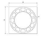
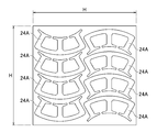
- the stator core 24 is manufactured by the four small cores 24A in this way, the number of the small cores 24A can be increased and the material used can be reduced. That is, for example, when a core is formed by stacking electromagnetic steel plates, as shown in FIG. 3, in the conventional annular shaped stator core 4, a rectangular region having a length H whose one side is longer than the diameter of the stator core 4. It is necessary to punch and laminate the electromagnetic steel sheet.
- eight small cores 24A can be produced from a rectangular region having a length H on one side. Can be increased to reduce the material associated with the core.
- the performance of the electric motor can be improved by effectively using the gap of the gap portion 27.
- the air gap of the gap portion 27 is set as a cooling gas flow path to improve the heat dissipation efficiency, thereby improving the performance.
- the radiating efficiency can be improved, thereby improving the performance.
- this gap can be used for the wiring space of the device in which the electric motor 10 is disposed and the space for arranging various members, thereby simplifying the configuration of the device.
- both end portions on the circumferential side of the small core 24A are formed so that the end portion of the core back 26 becomes the end portion of the tooth 25, and the core back 26 is formed with an arc shape on the outer peripheral side.
- the shape of the end portion and the shape of the outer peripheral side are appropriately modified according to the arrangement method and fixing method of the small core 24A described later.
- stator arrangement By the way, in the case of producing the stator core with the annular shape in FIG. 16 described above, the relative misalignment of the plurality of teeth can be sufficiently reduced by punching, and the stator core can be produced with high accuracy.
- the stator core 24 is produced by arranging the plurality of small cores 24A apart from each other by the gap portion 27 as in this embodiment, the production accuracy of the stator core 24 decreases, and as a result, the rotor 14 There is a risk that the magnetic poles of the stator 15 cannot be arranged close to each other.
- the positioning error between the small cores 24A is sufficiently reduced, and the accuracy of the stator core 24 is improved. I try to prevent the decline. Further, by effectively using the insulating member used for winding the coil, and holding the plurality of small cores 24A constituting the stator core 24 by the insulating member in the casing 11A, the stator core 24 is A reduction in the efficiency of the mounting work when the small core 24A is used is prevented.
- the coil 15 is wound around each tooth
- yen is arrange
- the coil can be wound by effectively utilizing the winding equipment applied to the stator core having the ring shape.
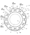
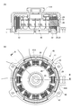
- FIG. 5 is a plan view (FIG. 5 (B)) showing a state where the stator 15 is arranged in the casing 11A, and a cross-sectional view (FIG. 5 (A)) taken along line AA.
- the insulator 28 is used as an insulating member for integrating the small cores 24A.
- the insulator 28 extends along the inner peripheral side of the core back 26 with the coil bobbin portion 29 provided for each tooth 25 of each small core 24A constituting the stator core 24 and the coil bobbin portion 29 of the tooth 25 in each small core 24A. It is formed in an annular shape by the connecting portion 30 that is connected in all shapes.
- the coil bobbin part 29 is comprised by the site
- the insulator 28 is a protective material for insulating the core and the magnet wire and preventing the magnet wire from being damaged during winding.
- a flame-retardant resin such as 66 nylon is injection-molded. Is produced.
- the insulator 28 includes an upper insulator 28A that covers each of the teeth 25 from above and a lower insulator 28B that covers each of the teeth 25 from below, and a small core is formed from both sides in the axial direction by the pair of insulators 28A and 28B.
- the four small cores 24A are integrated by sandwiching 24A.
- the coils 32 are wound around the teeth 25 to form the stator 15, and then incorporated into the casing 11A.
- both end portions of the core back 26 extend to the gap portion 27 side, and a through hole 33 is formed in the extended portion.
- the casing 11A is provided with a step 31 inside, and the stator 15 is positioned in the direction along the rotation axis by contacting the outer peripheral side portion of the core back 26 of each small core 24A with the step 31. .
- the casing 11 ⁇ / b> A is provided with a positioning hole 34 corresponding to the through-hole 33 at the level difference 31.
- the stator 15 can fix both ends of each small core 24 ⁇ / b> A in the circumferential direction to the case 11 by inserting the pin portion of the fixing pin 35 into the through hole 33 of the core back 26 and press-fitting into the positioning hole 34.
- the stator core 24 including the four small cores 24 ⁇ / b> A is supported by the case 11.
- the fixing pin 35 is formed in a U-shape, and the two pin portions of the fixing pin 35 are respectively inserted into the through holes 33 of the adjacent small cores 24A and press-fitted into the positioning holes. Adjacent ends of the core 24A are collectively fixed to the casing 11A to simplify the attaching operation of the stator 15.
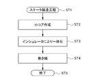
- FIG. 6 is a diagram showing a manufacturing process of the stator 15 according to this embodiment.
- a small core 24A is produced by punching and laminating electromagnetic steel sheets (steps ST1-ST2).
- step ST3 After the four small cores 24A are integrated using the insulator 28 (step ST3), coils are wound around the teeth 25 of the small cores 24A to produce the stator 15 (steps ST4-ST5).
- the teeth 25 are arranged in an annular shape, so that the winding in the conventional annularly shaped stator core 4 (FIG. 16) is performed. It can be performed in the same manner as the process.
- the stator core 4 is divided into a plurality of small cores 24A as shown in FIG.
- the stator 15 can be configured by the windings.
- the amount of material used can be reduced with respect to the core.
- the material used can be reduced due to the increase in the number of parts.
- the plurality of small cores 24A with the insulating member, it is possible to prevent an increase in man-hours for winding work and the like.
- the mounting error of the plurality of small cores 24A can be sufficiently reduced.
- the insulating members are a pair of insulators 28A and 28B, and a plurality of small cores 24A are sandwiched and integrated from both sides in the axial direction by the pair of insulators 28A and 28B, thereby configuring the pair of insulators 28A and 28B.
- the small cores 24A can be integrated by effectively utilizing the above.
- each small core 24A can be accurately used by effectively utilizing the configuration of the case 11. Can be held.
- FIG. 7 shows an electric motor according to a second embodiment of the present invention.
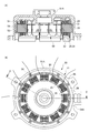
- FIG. 7B is a plan view showing a state where the stator 45 is arranged on the casing 41A
- FIG. 7A is this plan view.
- FIG. 6 is a cross-sectional view taken along the line BB, and is used for explaining the stator 45 by comparison with FIG.
- This embodiment is configured in the same way as the first embodiment except that the configuration of the fixing means of each small core 44A applied to the stator 45 is different.
- the four small cores 44A constituting the stator core are provided with fan-shaped convex portions 46 on the back side of the core back 26.
- a recess 42 for press-fitting the protrusion 46 is formed corresponding to each small core 44A.
- the stator 45 is held by the first casing 41A by press-fitting the convex portions 46 of the small cores 44A into the concave portions 42 of the first casing 41A from the axial direction.
- each convex part 46 fits in each concave part 42 in a wedge shape, each small core 44A does not shift in the radial direction with respect to the first casing 41A.
- each small core 44A can be fixed by press-fitting to the first casing 41A, and each small core 24A can be accurately held using a case, which is the same as in the first embodiment. An effect can be obtained.
- FIG. 8 shows an electric motor according to a third embodiment of the present invention.
- FIG. 8B is a plan view showing a state in which the stator 55 is arranged in the casing 51A, and FIG. 8A is this plan view.
- FIG. 6 is a cross-sectional view taken along line CC, and is used for explaining the stator 55 in comparison with FIG.
- This embodiment is configured in the same way as the first embodiment except that the configuration of the fixing means of the small core 54A applied to the stator 55 is different.
- Through holes 53 are formed at both ends of the core back 26 in the four small cores 54A constituting the stator core.
- a screw hole 54 corresponding to the through hole 53 is provided at the position of the step 31.
- each small core 54A can be fixed to the first casing 51A with a screw 56, and each small core 54A can be accurately held using a case, as in the first embodiment. The effect of can be obtained.
- FIG. 9 shows an electric motor according to a fourth embodiment of the present invention.
- FIG. 9B is a plan view showing a state in which the stator 65 is arranged in the casing 61A, and FIG. 9A is this plan view.
- FIG. 6 is a cross-sectional view taken along line DD, and is used for explaining the stator 65 in comparison with FIG.
- This embodiment is configured in the same way as the first embodiment except that the configuration of the fixing means of the small core 64A applied to the stator 65 is different.
- narrow grooves 67 and 66 are formed at positions corresponding to both ends of the small core 64A and both ends of the small core 64A in the casing 61A so as to obliquely cross the boundary between the small core 64A and the casing 61A. Is done.
- the metal plate material 68 is press-fitted across the narrow grooves 67 and 66, the small core 64A is held in the case, and the stator core is held in the case.
- FIG. 10 shows an electric motor according to a fifth embodiment of the present invention in comparison with FIG.
- the electric motor 70 according to this embodiment is configured in the same manner as the electric motor 10 of the first embodiment except that the configuration according to FIG. 10 and related configurations are different.
- the electric motor 70 is an outer rotor type three-phase brushless DC electric motor.
- a stator 75 is formed in a substantially cylindrical shape, and a rotor 74 is provided so as to surround the stator 75.
- the rotor 74 is provided with a magnet portion 73 having a large number of magnetic poles formed in the circumferential direction.
- a plurality of teeth 85 formed so that the tips thereof are opposed to the rotor 74 are arranged radially and at a constant angular interval in the circumferential direction, and a magnetic wire is wound around each of the teeth 85 to generate magnetic poles. It is formed.
- a predetermined number of adjacent teeth 85 are connected at their inner peripheral sides by a core back 86, and a magnetic closed circuit of the predetermined number of teeth 85 is formed.
- a predetermined number of teeth 85 are connected by a core back 86 to form a small core 84A.
- a plurality of such small cores 84A are arranged at regular intervals in the circumferential direction, and adjacent small cores 84A are mutually connected.
- a gap portion 87 where the core back 86 does not exist is provided between the adjacent teeth 85. That is, the stator 75 has a shape divided into small cores 84 ⁇ / b> A having a substantially arc shape (substantially fan shape) by the gap portion 87.
- the interval between the gap portions 87 is set so that the number of teeth 85 between the adjacent gap portions 87 is the number of phases M ⁇ n of the electric motor 70 (n is an integer of 1 or more). In this embodiment, n is set to a value of 1, and the number of teeth 85 between adjacent gap portions 87 is set to three.
- the stator 75 is fixed to the case by winding a coil after the small core 84A is integrated in the same manner as in the first to fourth embodiments. Even if this embodiment is applied to an outer rotor type electric motor, the same effects as those of the above-described embodiment can be obtained.
- FIG. 11 shows an electric motor according to a sixth embodiment of the present invention.
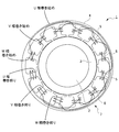
- FIG. 11 (B) is a plan view showing a state in which a stator 115 is arranged on a casing 111A
- FIG. 11 (A) is a plan view thereof.
- FIG. 6 is a cross-sectional view taken along line EE.
- 12A is an enlarged plan view showing the small core 124A in a state where the coil 132 is wound
- FIG. 12B is a cutaway view of FIG. 12A taken along line FF. It is sectional drawing.
- FIG. 12C is a plan view of the small core 124A.
- the insulator 128 is applied to an insulating member used for winding the coil 132.
- the insulator 128 is provided for each of the four small cores 124 ⁇ / b> A constituting the stator core 124, and the coil bobbin portion 129 that covers the three teeth 125 in the small core 124 ⁇ / b> A and the adjacent coil bobbin portion 129 are at least the inner periphery of the core back 126. It is formed by the connection part 130 connected by the shape along the side.
- the coil bobbin part 129 is comprised by the site
- the insulator 128 is a protective material for insulating the core and the magnet wire and further preventing the magnet wire from being damaged during winding.
- the insulator 128 is manufactured by injection molding a flame retardant resin such as 66 nylon. . 11 and 12, the insulator 128 includes an upper insulator 128A that covers each tooth 125 from above and a lower insulator 128B that covers each tooth 125 from below, and the pair of insulators 128A and 128B causes both sides in the axial direction.
- the small core 124A is sandwiched between and attached to the small core 124A.
- Each of the small cores 124A is disposed in the casing 111A after the coils 132 are wound around the teeth 125 via the coil bobbin portion 129, and the four small cores 124A are provided with gap portions 127 between the adjacent small cores 124A.
- the stator 115 is completed by being disposed in the casing 111A.
- both end portions of the core back 126 extend in a substantially rectangular shape in the outer peripheral direction, and a through hole 133 is formed in the extended portion.
- the casing 111A is provided with a step 131 on the inner side, and the step 131 abuts on the outer peripheral side portion of the core back 126 of the small core 124A, thereby positioning each small core 124A in the direction along the rotation axis.
- the casing 111 ⁇ / b> A is further provided with a screw hole at a position corresponding to the through hole 133.
- the small core 124A is supported by the case 111 by inserting screws 134 into the through holes 133 at both ends thereof and screwing them into the screw holes of the casing 111A.
- FIG. 13 is a diagram showing a manufacturing process of the stator 115 according to this embodiment.
- the small core 124A is manufactured by punching and laminating electromagnetic steel as described above (steps ST11 to ST12).
- the insulator 128 is disposed on the small core 124A (step ST13).
- a magnet wire is wound around each of the teeth 125 insulated by the insulator 128 (step ST14), whereby the coil 132 is wound around the small core 124A.
- each small core 124A is fixed to the case, and each small core 124A constituting the stator 115 is arranged in an annular shape and integrated. Further, a coil is connected for each phase, thereby producing a stator 115 (step ST15).
- the gap portion 127 where the core back is not provided between the adjacent teeth 125 it is possible to reduce the amount of material used for the core, and further, As a result of the increase, the material used can be reduced. Further, by providing an insulating member on each of the small cores 124A and winding the coils 132 so that the small cores 124A are integrally held by the case, an increase in work man-hours can be prevented, and moreover, The mounting error of the small core 124A can be sufficiently reduced depending on the case.
- stator 115 can be reliably held in the case with a simple configuration.
- FIG. 14 shows an electric motor according to a seventh embodiment of the present invention.
- FIG. 14 (B) is a plan view showing a state where the stator 145 is arranged on the casing 141A
- FIG. 14 (A) is this plan view.
- FIG. 6 is a cross-sectional view taken along line GG, and is used for explaining the stator 145 by comparison with FIG.
- This embodiment is configured in the same manner as the sixth embodiment except that the configuration of the fixing means of the small core 144A applied to the stator 145 is different.
- the small core 144A is provided with a fan-shaped convex portion 146 on the back side of the core back 126.
- the first casing 141A is formed with a concave portion 142 into which the convex portion 146 fits.
- the small core 144A is held by the first casing 141A by press-fitting the convex portion 146 into the concave portion 142 of the first casing 141A from the axial direction.
- a gap portion 127 is formed between the small cores 144A to form the stator 145, which is attached to the case.
- each small core 144A can be fixed to the first casing 141A by press-fitting, and the same effect as the above-described embodiment can be obtained.
- FIG. 15 is a diagram showing a small core 154A applied to the electric motor according to the eighth embodiment of the present invention.
- the small core 154A is formed by laminating a plurality of core sheets 151 produced by punching out electromagnetic steel sheets by pressing. During the lamination, the core sheets 151 are laminated so as to be displaced in the circumferential direction sequentially by a certain angle. As a result, in this embodiment, the small core 154A is formed so that the core sheet 151 gradually displaces in the circumferential direction including the portion of the tooth 125 that faces the rotor 114, thereby applying a skew.
- This embodiment is configured in the same manner as the sixth or seventh embodiment except that the skew is applied.
- the small core 154A is inclined so that the slots between the teeth 125 are oriented in the vertical direction.
- each can be wound through a magnet wire in a rectangular shape.
- the winding apparatus conventionally used.
- the insulator is omitted for the sake of explanation, but actually, the coil is wound after the insulator is mounted on the skewed small core 154A.
- a molding resin can be applied to the small core insulating member, and a plurality of small cores can be integrated by an insert mold using the molding resin.
- the same effect as the above-mentioned embodiment can be acquired by integrating a small core with the insert mold which uses mold resin.
- N may be set to a value of 2 to set the number of teeth between the gap portions to six.
- the number of teeth between the gap portions may be four or five larger than three, or may be a number other than the number of phases ⁇ n.
- the present invention is not limited to this, and motors having various numbers of phases such as two-phase, and various slots. It can be widely applied to electric motors.
- the present invention is not limited to the application to a brushless DC motor, but can be widely applied to various motors such as an inner rotor brush DC motor, an inner rotor AC motor, and an outer rotor AC motor.
- the present invention is not limited to this and can be widely applied to an inner rotor type and an outer rotor type generator.
- the rotating electrical machine according to the present invention can reduce the material used and reduce the cost as compared with the conventional one, and can be applied to various motors and generators of the inner rotor type and the outer rotor type.
Landscapes
- Engineering & Computer Science (AREA)
- Power Engineering (AREA)
- Iron Core Of Rotating Electric Machines (AREA)
Abstract
La présente invention concerne une machine électrique rotative à phase M (10) qui est formée en logeant un rotor (14) et un stator (15) dans un boîtier (11), ledit stator étant formé en enroulant une bobine autour de chacune d'une pluralité de dents (25) disposées de façon radiale. Dans la machine électrique rotative, le stator comporte une pluralité de petits noyaux (24A), chacun équipé d'un nombre prédéterminé de dents et d'un dos de noyau (26) pour accoupler les parties bases de ces dents et disposé dans une direction circonférentielle à des intervalles d'angle constant et est pourvu de régions entrefers (27) entre des petits noyaux adjacents. Les petits noyaux sont intégrés par un élément isolant annulaire (28) qui accouple les parties enroulements de bobine (29) des dents à travers une partie connexion (30). En variante, les petits noyaux sont intégrés de manière telle que l'élément isolant soit prévu, qui accouple les parties enroulements de bobine des dents à travers la partie connexion, la bobine est enroulée autour de chacune des dents, et alors le dos de noyau est fixé au boîtier par un moyen de fixation (33, 34, 35).
Applications Claiming Priority (4)
| Application Number | Priority Date | Filing Date | Title |
|---|---|---|---|
| JP2013130133A JP2015006069A (ja) | 2013-06-21 | 2013-06-21 | 回転電機及び回転電機の製造方法 |
| JP2013-130133 | 2013-06-21 | ||
| JP2013155281A JP2015027175A (ja) | 2013-07-26 | 2013-07-26 | 回転電機及び回転電機の製造方法 |
| JP2013-155281 | 2013-07-26 |
Publications (1)
| Publication Number | Publication Date |
|---|---|
| WO2014203849A1 true WO2014203849A1 (fr) | 2014-12-24 |
Family
ID=52104583
Family Applications (1)
| Application Number | Title | Priority Date | Filing Date |
|---|---|---|---|
| PCT/JP2014/065882 Ceased WO2014203849A1 (fr) | 2013-06-21 | 2014-06-16 | Machine électrique rotative et procédé de fabrication de machine électrique rotative |
Country Status (1)
| Country | Link |
|---|---|
| WO (1) | WO2014203849A1 (fr) |
Cited By (2)
| Publication number | Priority date | Publication date | Assignee | Title |
|---|---|---|---|---|
| CN107887998A (zh) * | 2017-12-05 | 2018-04-06 | 广东美的环境电器制造有限公司 | 直流电机和具有其的流体驱动装置 |
| CN113991897A (zh) * | 2021-11-06 | 2022-01-28 | 东莞市德玛电子有限公司 | 电机定子 |
Citations (4)
| Publication number | Priority date | Publication date | Assignee | Title |
|---|---|---|---|---|
| JPH11341714A (ja) * | 1998-05-28 | 1999-12-10 | Toshiba Corp | モータのステータ |
| JP2000188835A (ja) * | 1998-12-22 | 2000-07-04 | Toshiba Corp | モータ及びその製造方法 |
| JP2002345224A (ja) * | 2001-05-18 | 2002-11-29 | Yaskawa Electric Corp | 永久磁石形同期電動機 |
| JP2013090561A (ja) * | 2011-10-20 | 2013-05-13 | Lg Innotek Co Ltd | モータのステータコア及びその製造方法 |
-
2014
- 2014-06-16 WO PCT/JP2014/065882 patent/WO2014203849A1/fr not_active Ceased
Patent Citations (4)
| Publication number | Priority date | Publication date | Assignee | Title |
|---|---|---|---|---|
| JPH11341714A (ja) * | 1998-05-28 | 1999-12-10 | Toshiba Corp | モータのステータ |
| JP2000188835A (ja) * | 1998-12-22 | 2000-07-04 | Toshiba Corp | モータ及びその製造方法 |
| JP2002345224A (ja) * | 2001-05-18 | 2002-11-29 | Yaskawa Electric Corp | 永久磁石形同期電動機 |
| JP2013090561A (ja) * | 2011-10-20 | 2013-05-13 | Lg Innotek Co Ltd | モータのステータコア及びその製造方法 |
Cited By (3)
| Publication number | Priority date | Publication date | Assignee | Title |
|---|---|---|---|---|
| CN107887998A (zh) * | 2017-12-05 | 2018-04-06 | 广东美的环境电器制造有限公司 | 直流电机和具有其的流体驱动装置 |
| CN107887998B (zh) * | 2017-12-05 | 2024-04-19 | 广东美的环境电器制造有限公司 | 直流电机和具有其的流体驱动装置 |
| CN113991897A (zh) * | 2021-11-06 | 2022-01-28 | 东莞市德玛电子有限公司 | 电机定子 |
Similar Documents
| Publication | Publication Date | Title |
|---|---|---|
| CN108463939B (zh) | 无刷电动机的定子、无刷电动机以及无刷电动机的定子的制造方法 | |
| US9343934B2 (en) | Electric motor | |
| JP6434694B2 (ja) | 回転電機機械 | |
| JP6025998B2 (ja) | 磁気誘導子型電動機 | |
| WO2016059944A1 (fr) | Stator | |
| JP6545393B2 (ja) | コンシクエントポール型の回転子、電動機および空気調和機 | |
| US20190103781A1 (en) | Motor | |
| JP2018068069A (ja) | ステータ、モータ、およびステータの製造方法 | |
| JP2008193842A (ja) | アキシャルギャップ型回転電機 | |
| JP5248048B2 (ja) | 回転電機の回転子及び回転電機 | |
| CN101253668A (zh) | 包含带有倾斜齿的扁平定子的电机 | |
| JP6310984B2 (ja) | ブラシレスモータ及び固定子の巻線方法 | |
| US8987971B2 (en) | Rotor core for an electric machine | |
| WO2014192608A1 (fr) | Moteur sans balais à rotor interne | |
| JP5947230B2 (ja) | モータ | |
| JP2015027175A (ja) | 回転電機及び回転電機の製造方法 | |
| WO2014203849A1 (fr) | Machine électrique rotative et procédé de fabrication de machine électrique rotative | |
| KR20110008749A (ko) | 분할 스큐 코어 구조의 스테이터, 이를 이용한 bldc 모터 및 배터리 쿨링장치 | |
| JP6824348B2 (ja) | 単相ブラシレスモータ、単相ブラシレスモータの製造方法、単相ブラシレスモータを備えた電気掃除機、および電気掃除機の製造方法 | |
| JPWO2018180345A1 (ja) | 電動モータ用ステータおよび電動モータ | |
| JP2009077491A (ja) | ステータコア積層体およびモータ | |
| WO2018180344A1 (fr) | Stator pour moteur électrique, et moteur électrique | |
| JP2017225250A (ja) | 三相ブラシレスモータ | |
| JP2018125993A (ja) | 回転電機 | |
| JP2006087190A (ja) | 非円筒形状のギャップを有するモータ |
Legal Events
| Date | Code | Title | Description |
|---|---|---|---|
| 121 | Ep: the epo has been informed by wipo that ep was designated in this application |
Ref document number: 14814358 Country of ref document: EP Kind code of ref document: A1 |
|
| NENP | Non-entry into the national phase |
Ref country code: DE |
|
| 122 | Ep: pct application non-entry in european phase |
Ref document number: 14814358 Country of ref document: EP Kind code of ref document: A1 |