WO2014203975A1 - Dispositif de transport - Google Patents
Dispositif de transport Download PDFInfo
- Publication number
- WO2014203975A1 WO2014203975A1 PCT/JP2014/066322 JP2014066322W WO2014203975A1 WO 2014203975 A1 WO2014203975 A1 WO 2014203975A1 JP 2014066322 W JP2014066322 W JP 2014066322W WO 2014203975 A1 WO2014203975 A1 WO 2014203975A1
- Authority
- WO
- WIPO (PCT)
- Prior art keywords
- preform
- conveyance
- engaging means
- unit
- conveying
- Prior art date
- Legal status (The legal status is an assumption and is not a legal conclusion. Google has not performed a legal analysis and makes no representation as to the accuracy of the status listed.)
- Ceased
Links
Images


Classifications
-
- B—PERFORMING OPERATIONS; TRANSPORTING
- B29—WORKING OF PLASTICS; WORKING OF SUBSTANCES IN A PLASTIC STATE IN GENERAL
- B29C—SHAPING OR JOINING OF PLASTICS; SHAPING OF MATERIAL IN A PLASTIC STATE, NOT OTHERWISE PROVIDED FOR; AFTER-TREATMENT OF THE SHAPED PRODUCTS, e.g. REPAIRING
- B29C49/00—Blow-moulding, i.e. blowing a preform or parison to a desired shape within a mould; Apparatus therefor
- B29C49/42—Component parts, details or accessories; Auxiliary operations
- B29C49/4205—Handling means, e.g. transfer, loading or discharging means
- B29C49/42113—Means for manipulating the objects' position or orientation
- B29C49/42119—Rotation, e.g. rotating a predetermined angle for asymmetric preform or with asymmetric heat profile
-
- B—PERFORMING OPERATIONS; TRANSPORTING
- B65—CONVEYING; PACKING; STORING; HANDLING THIN OR FILAMENTARY MATERIAL
- B65G—TRANSPORT OR STORAGE DEVICES, e.g. CONVEYORS FOR LOADING OR TIPPING, SHOP CONVEYOR SYSTEMS OR PNEUMATIC TUBE CONVEYORS
- B65G47/00—Article or material-handling devices associated with conveyors; Methods employing such devices
- B65G47/22—Devices influencing the relative position or the attitude of articles during transit by conveyors
- B65G47/24—Devices influencing the relative position or the attitude of articles during transit by conveyors orientating the articles
- B65G47/244—Devices influencing the relative position or the attitude of articles during transit by conveyors orientating the articles by turning them about an axis substantially perpendicular to the conveying plane
-
- B—PERFORMING OPERATIONS; TRANSPORTING
- B29—WORKING OF PLASTICS; WORKING OF SUBSTANCES IN A PLASTIC STATE IN GENERAL
- B29C—SHAPING OR JOINING OF PLASTICS; SHAPING OF MATERIAL IN A PLASTIC STATE, NOT OTHERWISE PROVIDED FOR; AFTER-TREATMENT OF THE SHAPED PRODUCTS, e.g. REPAIRING
- B29C49/00—Blow-moulding, i.e. blowing a preform or parison to a desired shape within a mould; Apparatus therefor
- B29C49/42—Component parts, details or accessories; Auxiliary operations
- B29C49/4205—Handling means, e.g. transfer, loading or discharging means
- B29C49/42065—Means specially adapted for transporting preforms
-
- B—PERFORMING OPERATIONS; TRANSPORTING
- B29—WORKING OF PLASTICS; WORKING OF SUBSTANCES IN A PLASTIC STATE IN GENERAL
- B29C—SHAPING OR JOINING OF PLASTICS; SHAPING OF MATERIAL IN A PLASTIC STATE, NOT OTHERWISE PROVIDED FOR; AFTER-TREATMENT OF THE SHAPED PRODUCTS, e.g. REPAIRING
- B29C49/00—Blow-moulding, i.e. blowing a preform or parison to a desired shape within a mould; Apparatus therefor
- B29C49/42—Component parts, details or accessories; Auxiliary operations
- B29C49/4205—Handling means, e.g. transfer, loading or discharging means
- B29C49/42093—Transporting apparatus, e.g. slides, wheels or conveyors
-
- B—PERFORMING OPERATIONS; TRANSPORTING
- B29—WORKING OF PLASTICS; WORKING OF SUBSTANCES IN A PLASTIC STATE IN GENERAL
- B29C—SHAPING OR JOINING OF PLASTICS; SHAPING OF MATERIAL IN A PLASTIC STATE, NOT OTHERWISE PROVIDED FOR; AFTER-TREATMENT OF THE SHAPED PRODUCTS, e.g. REPAIRING
- B29C2949/00—Indexing scheme relating to blow-moulding
- B29C2949/07—Preforms or parisons characterised by their configuration
- B29C2949/0715—Preforms or parisons characterised by their configuration the preform having one end closed
-
- B—PERFORMING OPERATIONS; TRANSPORTING
- B29—WORKING OF PLASTICS; WORKING OF SUBSTANCES IN A PLASTIC STATE IN GENERAL
- B29C—SHAPING OR JOINING OF PLASTICS; SHAPING OF MATERIAL IN A PLASTIC STATE, NOT OTHERWISE PROVIDED FOR; AFTER-TREATMENT OF THE SHAPED PRODUCTS, e.g. REPAIRING
- B29C49/00—Blow-moulding, i.e. blowing a preform or parison to a desired shape within a mould; Apparatus therefor
- B29C49/02—Combined blow-moulding and manufacture of the preform or the parison
- B29C49/06—Injection blow-moulding
-
- B—PERFORMING OPERATIONS; TRANSPORTING
- B29—WORKING OF PLASTICS; WORKING OF SUBSTANCES IN A PLASTIC STATE IN GENERAL
- B29C—SHAPING OR JOINING OF PLASTICS; SHAPING OF MATERIAL IN A PLASTIC STATE, NOT OTHERWISE PROVIDED FOR; AFTER-TREATMENT OF THE SHAPED PRODUCTS, e.g. REPAIRING
- B29C49/00—Blow-moulding, i.e. blowing a preform or parison to a desired shape within a mould; Apparatus therefor
- B29C49/42—Component parts, details or accessories; Auxiliary operations
- B29C49/4205—Handling means, e.g. transfer, loading or discharging means
- B29C49/42051—Means for stripping, aligning or de-stacking
- B29C49/42057—Aligning disorderly arranged preforms, e.g. delivered disorderly
-
- B—PERFORMING OPERATIONS; TRANSPORTING
- B65—CONVEYING; PACKING; STORING; HANDLING THIN OR FILAMENTARY MATERIAL
- B65G—TRANSPORT OR STORAGE DEVICES, e.g. CONVEYORS FOR LOADING OR TIPPING, SHOP CONVEYOR SYSTEMS OR PNEUMATIC TUBE CONVEYORS
- B65G2201/00—Indexing codes relating to handling devices, e.g. conveyors, characterised by the type of product or load being conveyed or handled
- B65G2201/02—Articles
- B65G2201/0235—Containers
- B65G2201/0244—Bottles
Definitions
- the present invention relates to a transfer device.
- an injection stretch blow molding apparatus called a 1.5 stage system is known as a blow molding apparatus in which a preform is disposed in a blow cavity mold and the preform is blow molded into a container (for example, Patent Document 1). reference).
- This 1.5-stage injection stretch blow molding apparatus is a one-stage system in which injection molding and blow molding are connected inline, but the advantage of two stages in which the number of simultaneous injection moldings and the number of simultaneous blow moldings do not match have.
- a conveyance line for continuously conveying the preform is provided.
- the transport line includes a plurality of sprockets, a plurality of transport members that can be engaged with the plurality of sprockets, and a guide rail that guides the transport members along the transport direction. It is what you have.
- the preform when the container has a uniform shape in the radial direction, such as being substantially circular in a top view, the preform also has a uniform shape that is substantially circular in a top view.
- the shape of the preform may not be uniform in the radial direction of the preform, for example, the preform may be elliptical when viewed from above or the thickness of the preform may not be uniform.
- Such a preform is used, for example, when a flat container or a rectangular container is formed.
- Patent Document 2 is complicated in control, and the apparatus itself may be expensive.
- the preform is heated from the room temperature, using a preform having a thick portion in the radial direction is disadvantageous in terms of energy.
- the blow molding apparatus of 1 to 1.5 stage method as in Patent Document 1 can use the heat remaining in the preform after injection molding, so-called retained heat.
- the value of the retained heat is larger as the thickness is larger. That is, a flat container having a uniform wall thickness distribution can be formed by only thickening the preform side corresponding to the major axis of the container without taking a special heating method. Moreover, it can be said that it is more advantageous in terms of energy than the two-stage method because the heat stored in the preform can be utilized.
- the 1.5 stage blow molding apparatus needs to be in an aligned state in which the preforms are aligned in the direction according to the major axis and minor axis of the blow cavity mold.
- the preform held on the conveying member since the preform held on the conveying member is not in a state where the preform and the conveying member are closely fitted to each other, the preform is brought into contact with the conveying member due to vibration accompanying conveyance. On the other hand, it may rotate, and the orientation of the preform being conveyed may shift. For example, when the preform has an elliptical shape, the major axis direction of the preform being conveyed may be displaced.
- the preforms being conveyed are in an unaligned state in which the directions of the preforms are not uniform, and there is a problem that if the blow molding process is performed in this state, a desired blow molding cannot be performed.
- an object of the present invention is to solve the above-described problems of the prior art, and an object of the present invention is to provide a transport device that can align the directions of the preforms during continuous transport.
- the transport device of the present invention is a transport device for transporting a preform for blow molding, the transport device transporting the preform while rotating in the horizontal direction, and the preform being transported while rotating. And an engaging means for adjusting the orientation of the preform in a predetermined direction, wherein the engaging means is engaged with a convex portion or a concave portion provided on the outer periphery of the preform.
- an engagement means that engages the preform being conveyed while the conveying device is rotated and arranges the orientation of the preform in a predetermined direction, so that each preform is conveyed during continuous conveyance.
- the direction can be aligned.
- the engaging means includes a rolling member, and the rolling member is configured to be movable in a groove formed in the conveying device, and the groove is formed between the engaging means and the preform at a predetermined position.
- the retracting portion is preferably formed so that the relative distance becomes long. Since the retracting portion is formed, the engaging means can be easily separated from the preform, and as a result, the directions of the preforms can be made more uniform during continuous conveyance.
- the engaging means has a support portion provided at one end thereof with a protruding portion formed so as to engage with a concave portion formed in the preform. It is mentioned that the end is fixed and the one end is biased outward.
- the transport apparatus of the present invention it is possible to achieve an excellent effect that the directions of the preforms can be made uniform during continuous transport.
- the schematic diagram which shows a shaping
- a molding apparatus 100 including a transport device includes an injection molding unit 110 that performs injection molding of a preform 200 that is a container body, and a preform 200 that is molded by the injection molding unit 110.
- a cooling unit 120 for cooling, a heating unit 130 for heating the preform 200, and a blow molding unit 140 for blow molding the preform 200 arranged in the blow cavity mold are provided.
- the molding apparatus 100 includes a transport unit 150 including a transport line 151 that constitutes a loop-shaped transport line that circulates from the cooling unit 120 to the heating unit 130 and the blow molding unit 140.
- the transport unit 150 transports the preform 200 from the cooling unit 120 to the heating unit 130 and transports the preform 200 heated by the heating unit 130 to the blow molding unit 140.
- the molding apparatus 100 is characterized by the transport apparatus 300 in the transport section 150, and the configuration of each section will be described in detail below.
- the structure of the injection molding part 110, the cooling part 120, the heating part 130, and the blow molding part 140 is a well-known thing, it demonstrates easily here (If necessary, if this is the case, the international publication 2013 / No. 027692).
- the injection molding unit 110 includes a mold clamping mechanism 111, and although not illustrated, the core mold arranged above and the cavity mold arranged below are clamped by the mold clamping mechanism 111.
- the preform 200 is injection-molded by filling a resin material (raw material) with an injection device into an injection space defined by the core mold and the cavity mold.
- a resin material raw material
- the preform 200 has a different thickness in the radial direction, and a recess 201 (see FIG. 2) is provided on the outer peripheral surface thereof.
- the cooling unit 120 forcibly cools the injection-molded preform 200.
- the preform 200 injection-molded by the injection-molding unit 110 is transported from the injection-molding unit 110 to the cooling unit 120 by a transport device (not shown), and is forcedly cooled by the cooling unit 120.
- the preform 200 cooled to a predetermined temperature by the cooling unit 120 is unloaded to a transfer line 151 constituting the transfer unit 150 and continuously transferred.
- the preform 200 is molded in an upright state with the neck portion facing upward in the injection molding unit 110, and is conveyed from the injection molding unit 110 to the cooling unit 120 in this state.
- the cooling unit 120 has a reversing mechanism (not shown) for reversing the preform 200 thus conveyed in an upright state into an inverted state with the neck portion facing downward.
- the preform 200 is inverted by the reversing mechanism while being cooled by the cooling unit 120, and is held by the conveying jig 152 provided in the conveying unit 150.
- the conveyance line 151 is configured such that these conveyance jigs 152 are sequentially and sequentially conveyed by the driving force of the sprocket 154 and the like, so that the preform 200 held by the conveyance jig 152 is conveyed. .
- transfer jigs 152 are arranged in a plurality of rows below the cooling unit 120. Then, the conveyance jigs 152 holding the preform 200 are alternately carried out to the conveyance line 151. Thereafter, the preform 200 held by the transport jig 152 is transported along the transport line 151 and carried into the heating unit 130.
- the conveyance jig 152 that holds the preform 200 cooled by the cooling unit 120 is heated to the proper stretching temperature while being moved along the conveyance line 151.
- the entire preform 200 is heated uniformly by heating the preform 200 while rotating in the heating unit 130.
- the conveyance line 151 is provided with a curved conveyance unit 155 that is curved with a predetermined radius on the downstream side of the heating unit 130, and the curved conveyance unit 155 includes Correspondingly, a transfer device 300 is provided.
- the transport device 300 adjusts the orientation of the preform 200 being transported in a predetermined direction. Therefore, all the preforms 200 that have passed through the curved conveyance unit 155 are aligned in a state in which they are directed in a predetermined direction.
- the conveyance jig 152 holding the preform 200 is conveyed from the curved conveyance unit 155 along the conveyance line 151 and is carried into the blow molding unit 140.
- the preform 200 held in the inverted state is inverted by a predetermined number (for example, eight) by a transfer arm (not shown) and taken out as an upright state.
- a predetermined number of preforms 200 received from the transfer unit 160 are conveyed to a blow cavity mold 141 composed of a pair of split molds, and the preform 200 is blow molded by the blow cavity mold 141.
- the presence of the conveying device 300 described below makes it possible to align the orientations of preforms having different thicknesses in the radial direction, and as a result, desired blow molding can be performed.
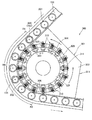
- FIG. 2 is a partially enlarged view of the vicinity of the curved conveyance unit in FIG. 1 for explaining the conveyance device
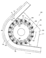
- FIG. 3 is a diagram in which the preform is removed from FIG. 2 for explaining the conveyance device.
- the conveyance device 300 provided corresponding to the curved conveyance unit 155 includes an engagement device 301 for adjusting the orientation of the preform 200 being conveyed in a predetermined direction.
- the engagement device 301 includes a plurality of engagement means 310 that engage with the preform 200 conveyed along the conveyance line 151 and adjust the orientation of the preform 200 in a predetermined direction.
- the transport apparatus 300 according to the present invention includes the transport line 151, a transport unit that transports the transport jig 152 on the transport line 151, and a plurality of engagement units 310.
- the engaging device 301 is formed corresponding to the curved conveyance unit 155 and includes a pedestal unit 303 having a curved portion 302 that is curved corresponding to a curved portion of the curved conveyance unit 155.
- a columnar portion 304 is provided on the pedestal portion 303.
- the columnar portion 304 is configured to be able to rotate in the horizontal direction around the center thereof. This rotation direction of the columnar section 304 is set to be the same as the conveyance direction. That is, it is counterclockwise in FIGS.
- Each engagement means 310 is fixed to the columnar portion 304 in a state of being separated from each other by a predetermined distance. Since the columnar portion 304 has a polygonal shape that can be said to be a substantially circular shape in a top view, it can be said that the engaging means 310 are provided at predetermined intervals in the circumferential direction.
- the pedestal portion 303 has a substantially circular groove 305 in a top view.
- the groove 305 has a cam structure.
- a rolling member 314 of the engaging means 310 described later is inserted into the groove 305.
- the groove portion 305 has a retracting portion 306 recessed at the columnar portion 304 side, that is, inward at a predetermined position.
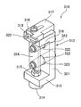
- Each engagement means 310 includes a first support portion 312.
- the first support portion 312 is a U-shaped member in a side view.
- a rolling member 314 such as a cam follower, for example, is provided on the bottom surface portion 313 constituting the bottom surface of the first support portion 312 so as to extend vertically downward.
- the rolling member 314 is fastened by a fastening member 315 at the bottom surface portion 313. This rolling member 314 is inserted into the groove 305 (see FIG. 2) having a cam structure as described above.
- a second support portion 317 is provided above the upper surface portion 316 constituting the upper surface of the first support portion 312.
- An engaging portion 319 is provided at a tip 318 of the second support portion 317 on the side of the conveyance line 151 (see FIGS. 2 and 3). One end of the engaging portion 319 is supported by the tip 318 and the other end is not supported. The engaging portion 319 is in a so-called cantilever state, and the other end is biased to the outside (the side opposite to the second support portion 317). Has been.
- the other end of the engaging portion 319 is a protruding portion 320 that protrudes toward the conveyance line 151 (see FIGS. 2 and 3).
- the protrusion 320 has a shape corresponding to the recess 201 (see FIG. 2) as will be described in detail later.
- the protruding portion 320 of the engaging portion 319 is configured to run on the transport line 151 in a region facing the transport line 151 (see FIG. 3).
- each engagement means 310 two through holes 322 are formed in the back surface portion 321 that constitutes between the bottom surface portion 313 and the top surface portion 316 of the first support portion 312, and each through hole 322 is defined as two cylindrical portions 323. Is provided through.
- the base end side (at least one) of each columnar part 323 is fixed to the columnar part 304 (see FIGS. 2 and 3), and a plate-like shape extends over each columnar part 323 on the distal end side of each columnar part 323.
- the part 324 is fixed.
- the predetermined distance between the engaging means 310 provided in the columnar part 304 is equal to the distance between the conveying jigs 152, that is, the distance of the preform 200.
- the operating state of the transfer device 300 will be described below.
- each engaging means 310 is fixed to the columnar portion 304 by the columnar portion 323.
- the rolling member 314 is inserted into the groove 305, the rolling member 314 moves along the groove 305 as the columnar part 304 rotates. That is, the groove portion 305 functions as a guide groove for the engaging means 310.
- the groove portion 305 has a retracting portion 306 that is recessed (inwardly) on the columnar portion 304 side at a predetermined position, when the engaging means 310 reaches the retracting portion 306, the groove portion 305 moves inward along the shape of the retracting portion 306. evacuate. Then, after passing through the retracting portion 306, it moves along the substantially circular groove portion 305 again.
- the preform 200 conveyed in the conveyance direction (indicated by arrows in FIGS. 2 and 3) near the curved conveyance unit 155 will be described.
- the conveying speed of the preform 200 and the rotation speed of the columnar part 304 are coincident, and the distance between the preforms 200 in the bending part 302 and the distance between the engaging means 310 are coincident.
- the engaging means 310 and the preform 200 always move while facing each other.
- the movement between the preform 200 and the engaging means 310 is performed at the same time.
- the conveyance jig 152 rotates in the horizontal direction around the center as an axis center during conveyance. Specifically, for example, when the sprocket provided on the conveyance jig 152 is fitted to a roller chain provided on the conveyance line 151, the conveyance jig 152 rotates. Further, the placed preform 200 rotates as the conveying jig 152 rotates. However, when the preform 200 is engaged with the engaging means 310 as described later, the preform 200 does not rotate. Only the conveyance jig 152 rotates while being conveyed.
- the position where rotation in the conveyance direction of the conveyance line 151 starts is defined as rotation start position R1, and the position where rotation ends is defined as rotation end position R2.
- the rotation region RR is defined from the rotation start position R1 to the rotation end position R2.
- the rotation region RR ends on the upstream side in the transport direction with respect to the position facing the retracting unit 306.
- a roller chain is provided over the rotation region RR.
- the rotation region RR is set so that the preform 200 can rotate at least once from the rotation start position R1 to the rotation end position R2 unless the preform 200 is engaged with the engagement means 310.
- the preform 200 when the preform 200 is conveyed in the vicinity of the curved conveyance unit 155, the positions of the recesses 201 are directed in different directions (not aligned), and the orientation of the preform 200 is uniform. Not so.
- the preform 200 is conveyed and flows into the rotation region RR.
- the preform 200 In the rotation region RR, the preform 200 is conveyed while rotating.
- the protrusion 320 of the engaging means 310 is fitted into the recess 201 provided in the preform 200.
- the protrusion part 320 fits into the recessed part 201, only the conveyance jig
- the engaging means 310 is retracted by the retracting portion 306 at the same time when the preform 200 is unloaded from the rotation region RR, the engaging portion 319, that is, the protruding portion 320 is detached from the preform 200, and the preform 200 is It is conveyed in the state. That is, the preforms 200 on the downstream side in the transport direction from the position corresponding to the retracting unit 306 are all transported with the recesses 201 aligned in the same direction (aligned state).
- FIG. 5 shows the state of conveyance of one preform 200 in the curved conveyance section 155, and the conveyance position of the preform 200 for each hour and one engagement means that engages the preform 200 in opposition to each other. 310. That is, FIG. 5 shows a plurality of preforms 200 and engaging means 310, but they are all the same preform 200 and engaging means 310, and indicate their positions at each time.
- the preform 200 is conveyed to the curved conveyance unit 155 from the upstream side.
- the engaging means 310 also moves along the groove 305.
- the preform 200 is transported to just before the rotation start position R1 of the curved transport section 155.
- the concave portion 201 faces outward.
- the engaging means 310 (t1) has not yet faced the preform 200 (t1).
- the preform 200 when the preform 200 reaches the rotation start position R1, the preform 200 also starts rotating by the conveyance jig 152 (see FIG. 2) starting rotation from the rotation start position R1.
- the rotation direction is the direction indicated by the arrow.
- the preform 200 is conveyed while rotating in the rotation region RR.
- the preform 200 (t2) at time t2 in the vicinity of the rotation start position R1 is not yet opposed to the engaging means 310 (t2) at this time.
- the preform 200 is further conveyed, and at time t3, the preform 200 (t2) faces the engaging means 310 (t3).
- the projecting portion 320 of the engaging means 310 is not engaged with the concave portion 201 of the preform 200 (t3), and is thus pressed and retracted by the preform 200 (t3).
- the preform 200 (t3) continues to rotate while being transported, and the engaging means 310 (t3) is opposed to the preform 200, and the projecting portion 320 moves while being pressed against the preform 200.
- the concave portion 201 of the preform 200 (t4) is completely turned inward and engaged with the protrusion 320 of the engaging means 310 (t4).
- the preform 200 rotates in the rotation region RR, so that the concave portion 201 of the preform 200 is always engaged regardless of the position of the preform 200 that is conveyed to the curved conveyance unit 155. It is configured to engage with the engaging portion 319 of the combining means 310.
- the engaging means 310 moves along the groove part 305, the engaging means 310 retracts in the retracting part 306 at time t4.
- the engaging portion 319 of the engaging means 310 is separated from the recessed portion 201 of the preform 200 to be conveyed, and the engagement ends.
- the preform 200 being simultaneously conveyed can be conveyed without changing its direction.
- the groove portion 305 is configured not to have the retracting portion 306, when the protruding portion 320 is separated from the concave portion 201 of the preform 200, the protruding portion 320 is caught by the concave portion 201 and the preform 200 rotates. The direction of the preform 200 will change. Then, as shown in FIG. 2, it is difficult to align the directions of the preforms 200 that have passed through the curved conveyance unit 155 in the same direction. Therefore, it is desirable that the groove 305 has a retracting portion 306 as in the present embodiment to prevent the protruding portion 320 from being caught when coming out of the recess 201.
- the orientation of the preform 200 is aligned even when the preform 200 is loaded into the blow molding unit 140.
- Desired blow molding can be performed in the molding unit 140.
- the engaging portion 319 is supported by the tip 318 at one end, and is biased to the outside in a state where the other end is not supported, thereby engaging the recess 201 of the preform 200. Easy to match.
- the orientations of the preforms 200 can be made uniform during continuous transport.
- the present invention is not limited to the embodiment described above.
- the curved conveyance unit 155 is provided between the heating unit 130 and the blow molding unit 140, but the arrangement of the curved conveyance unit 155 is not limited to this.
- the curved conveyance unit 155 may be provided in front of the heating unit 130.
- the configuration in which the protruding portion 320 of the engaging means 310 is engaged with the recess 201 formed in the preform 200 is exemplified, but the configuration for the engaging means 310 to engage with the reform 200 is particularly It is not limited.
- a convex portion may be formed on the preform 200, and the convex portion may be pressed and engaged with the convex portion formed on the engaging portion 319.
- the transport device 300 continuously transports only the preform 200
- the configuration of the transport device is not limited to this.
- the conveying device may alternately convey the preform and the handle provided to the bottle.
Landscapes
- Engineering & Computer Science (AREA)
- Mechanical Engineering (AREA)
- Manufacturing & Machinery (AREA)
- Blow-Moulding Or Thermoforming Of Plastics Or The Like (AREA)
Abstract
Priority Applications (4)
| Application Number | Priority Date | Filing Date | Title |
|---|---|---|---|
| JP2015522982A JP6103402B2 (ja) | 2013-06-21 | 2014-06-19 | 搬送装置 |
| EP14813278.0A EP3012086B1 (fr) | 2013-06-21 | 2014-06-19 | Dispositif de transport |
| CN201480035387.2A CN105358303B (zh) | 2013-06-21 | 2014-06-19 | 运送装置 |
| US14/974,344 US9580252B2 (en) | 2013-06-21 | 2015-12-18 | Transport apparatus |
Applications Claiming Priority (2)
| Application Number | Priority Date | Filing Date | Title |
|---|---|---|---|
| JP2013-130738 | 2013-06-21 | ||
| JP2013130738 | 2013-06-21 |
Related Child Applications (1)
| Application Number | Title | Priority Date | Filing Date |
|---|---|---|---|
| US14/974,344 Continuation US9580252B2 (en) | 2013-06-21 | 2015-12-18 | Transport apparatus |
Publications (1)
| Publication Number | Publication Date |
|---|---|
| WO2014203975A1 true WO2014203975A1 (fr) | 2014-12-24 |
Family
ID=52104701
Family Applications (1)
| Application Number | Title | Priority Date | Filing Date |
|---|---|---|---|
| PCT/JP2014/066322 Ceased WO2014203975A1 (fr) | 2013-06-21 | 2014-06-19 | Dispositif de transport |
Country Status (6)
| Country | Link |
|---|---|
| US (1) | US9580252B2 (fr) |
| EP (1) | EP3012086B1 (fr) |
| JP (1) | JP6103402B2 (fr) |
| CN (1) | CN105358303B (fr) |
| TW (1) | TWI580555B (fr) |
| WO (1) | WO2014203975A1 (fr) |
Cited By (1)
| Publication number | Priority date | Publication date | Assignee | Title |
|---|---|---|---|---|
| WO2016121948A1 (fr) * | 2015-01-29 | 2016-08-04 | 日精エー・エス・ビー機械株式会社 | Appareil de transport |
Families Citing this family (5)
| Publication number | Priority date | Publication date | Assignee | Title |
|---|---|---|---|---|
| FR3045446B1 (fr) * | 2015-12-16 | 2018-01-12 | Sidel Participations | Indexation angulaire d'une preforme chauffee non uniformement par mesure de temperature |
| DE102016007850A1 (de) * | 2016-06-29 | 2018-01-04 | Khs Corpoplast Gmbh | Heizvorrichtung für eine Blasmaschine mit faltbarer Förderkette |
| NL2017196B1 (en) | 2016-07-20 | 2018-01-26 | Sluis Cigar Machinery Bv | Simulated cigarette parts reorienting apparatus |
| US11713145B2 (en) * | 2019-03-04 | 2023-08-01 | Illinois Tool Works Inc. | Variable pitch starwheel for container carrier applicating machine |
| FR3106294B1 (fr) * | 2020-01-22 | 2022-01-28 | Sidel Participations | Unité de chauffe pour préforme en matière plastique |
Citations (5)
| Publication number | Priority date | Publication date | Assignee | Title |
|---|---|---|---|---|
| JPH08504699A (ja) | 1993-04-15 | 1996-05-21 | シデル | 熱可塑性材料製のプレフォーム又は中間段階の容器におけるボディを熱処理する方法及び装置 |
| JP2000202899A (ja) * | 1999-01-08 | 2000-07-25 | Nissei Asb Mach Co Ltd | プリフォ―ム位置決め装置 |
| JP2006062136A (ja) * | 2004-08-25 | 2006-03-09 | Nissei Asb Mach Co Ltd | ブロー成形装置及びブロー成形方法並びにプリフォーム |
| JP2011528629A (ja) * | 2008-07-18 | 2011-11-24 | エス.アイ.ピー.エイ.ソシエタ’インダストリアリザッジオーネ プロゲッタジオーネ エ オートマジオーネ ソシエタ ペル アチオニ | プラスチック材容器のためのコンベアシステム |
| WO2013027692A1 (fr) | 2011-08-22 | 2013-02-28 | 日精エー・エス・ビー機械株式会社 | Procédé de moulage par soufflage pour récipient muni d'une poignée et équipement de moulage par soufflage |
Family Cites Families (17)
| Publication number | Priority date | Publication date | Assignee | Title |
|---|---|---|---|---|
| US3618743A (en) * | 1969-11-05 | 1971-11-09 | Mead Corp | Article-orienting device |
| DE3022343C2 (de) * | 1980-06-14 | 1983-10-20 | Kronseder, Hermann, 8404 Wörth | Vorrichtung zum Ausrichten von Flaschen o.dgl., insbesondere in Etikettiermaschinen |
| FR2595294B1 (fr) * | 1986-03-04 | 1988-07-08 | Sidel Sa | Procede et installation pour fabriquer des recipients, tels que des bouteilles, en polyethyleneterephtalate, resistant a des conditions thermiques relativement severes au cours de leur utilisation |
| JPH02139212A (ja) * | 1988-02-29 | 1990-05-29 | Toyo Seikan Kaisha Ltd | 把手付延伸ブロー成形容器の製法 |
| FR2646632B1 (fr) * | 1989-05-03 | 1991-11-15 | Sidel Sa | Installation de fabrication de corps creux en matiere plastique a partir de preformes, equipee de moyens de basculement de ces preformes |
| US5058724A (en) * | 1990-11-08 | 1991-10-22 | Hinton Gaylen R | Apparatus and method for orienting articles and containers |
| JP3212378B2 (ja) * | 1992-08-29 | 2001-09-25 | 株式会社キリンテクノシステム | 容器検査装置 |
| FR2736299B1 (fr) * | 1995-07-05 | 1997-09-05 | Sidel Sa | Procede et dispositif d'indexation angulaire pour disposer une preforme, une ebauche ou un recipient dans une position angulaire predeterminee, et preforme ou ebauche agencee pour leur mise en oeuvre |
| US6308816B1 (en) * | 2000-02-11 | 2001-10-30 | New England Machinery, Inc. | Rotary orienter indexing system |
| JP3705244B2 (ja) * | 2002-06-17 | 2005-10-12 | 東洋製罐株式会社 | 中空体把持用のグリッパ装置 |
| DE102004026755A1 (de) * | 2004-05-29 | 2005-12-22 | Krones Ag | Maschine zum Ausrichten und Ausstatten von Gegenständen |
| US20070042074A1 (en) * | 2005-08-19 | 2007-02-22 | Husky Injection Molding Systems Ltd. | Apparatus & molding system for rotating molded articles |
| DE102005041120A1 (de) * | 2005-08-30 | 2007-03-01 | Krones Ag | Vorrichtung und Verfahren zum Höhenausgleich in Behälterbehandlungsmaschinen |
| ATE527092T1 (de) * | 2006-08-07 | 2011-10-15 | Sacmi | Vorrichtung mit einer fördereinrichtung |
| JP5194227B2 (ja) * | 2007-12-28 | 2013-05-08 | キリンテクノシステム株式会社 | プリフォーム用吸着ヘッド、及びこれを用いたプリフォーム搬送装置並びにプリフォーム検査装置 |
| CN201721031U (zh) * | 2010-06-22 | 2011-01-26 | 铨宝工业股份有限公司 | 多空间容器的吹塑成型机 |
| EP2633976B1 (fr) * | 2010-10-25 | 2019-07-10 | Nissei Asb Machine Co., Ltd. | Dispositif de moulage par étirage-soufflage par injection |
-
2014
- 2014-06-19 WO PCT/JP2014/066322 patent/WO2014203975A1/fr not_active Ceased
- 2014-06-19 JP JP2015522982A patent/JP6103402B2/ja active Active
- 2014-06-19 CN CN201480035387.2A patent/CN105358303B/zh active Active
- 2014-06-19 EP EP14813278.0A patent/EP3012086B1/fr active Active
- 2014-06-20 TW TW103121364A patent/TWI580555B/zh active
-
2015
- 2015-12-18 US US14/974,344 patent/US9580252B2/en active Active
Patent Citations (5)
| Publication number | Priority date | Publication date | Assignee | Title |
|---|---|---|---|---|
| JPH08504699A (ja) | 1993-04-15 | 1996-05-21 | シデル | 熱可塑性材料製のプレフォーム又は中間段階の容器におけるボディを熱処理する方法及び装置 |
| JP2000202899A (ja) * | 1999-01-08 | 2000-07-25 | Nissei Asb Mach Co Ltd | プリフォ―ム位置決め装置 |
| JP2006062136A (ja) * | 2004-08-25 | 2006-03-09 | Nissei Asb Mach Co Ltd | ブロー成形装置及びブロー成形方法並びにプリフォーム |
| JP2011528629A (ja) * | 2008-07-18 | 2011-11-24 | エス.アイ.ピー.エイ.ソシエタ’インダストリアリザッジオーネ プロゲッタジオーネ エ オートマジオーネ ソシエタ ペル アチオニ | プラスチック材容器のためのコンベアシステム |
| WO2013027692A1 (fr) | 2011-08-22 | 2013-02-28 | 日精エー・エス・ビー機械株式会社 | Procédé de moulage par soufflage pour récipient muni d'une poignée et équipement de moulage par soufflage |
Non-Patent Citations (1)
| Title |
|---|
| See also references of EP3012086A4 |
Cited By (7)
| Publication number | Priority date | Publication date | Assignee | Title |
|---|---|---|---|---|
| WO2016121948A1 (fr) * | 2015-01-29 | 2016-08-04 | 日精エー・エス・ビー機械株式会社 | Appareil de transport |
| CN107206660A (zh) * | 2015-01-29 | 2017-09-26 | 日精Asb机械株式会社 | 输送装置 |
| JPWO2016121948A1 (ja) * | 2015-01-29 | 2017-11-02 | 日精エー・エス・ビー機械株式会社 | 搬送装置 |
| US10035664B2 (en) | 2015-01-29 | 2018-07-31 | Nissei Asb Machine Co., Ltd. | Transport apparatus |
| JP2019010880A (ja) * | 2015-01-29 | 2019-01-24 | 日精エー・エス・ビー機械株式会社 | 搬送装置 |
| US10196217B2 (en) | 2015-01-29 | 2019-02-05 | Nessei Asb Machine Co., Ltd. | Transport apparatus |
| CN107206660B (zh) * | 2015-01-29 | 2019-07-30 | 日精Asb机械株式会社 | 输送装置 |
Also Published As
| Publication number | Publication date |
|---|---|
| CN105358303B (zh) | 2017-10-03 |
| JPWO2014203975A1 (ja) | 2017-02-23 |
| TW201522002A (zh) | 2015-06-16 |
| US9580252B2 (en) | 2017-02-28 |
| CN105358303A (zh) | 2016-02-24 |
| US20160101946A1 (en) | 2016-04-14 |
| EP3012086A4 (fr) | 2017-03-08 |
| EP3012086A1 (fr) | 2016-04-27 |
| EP3012086B1 (fr) | 2020-04-15 |
| JP6103402B2 (ja) | 2017-03-29 |
| TWI580555B (zh) | 2017-05-01 |
Similar Documents
| Publication | Publication Date | Title |
|---|---|---|
| JP6103402B2 (ja) | 搬送装置 | |
| JP5997786B2 (ja) | ハンドル付容器のブロー成形方法 | |
| JP6118529B2 (ja) | 成形品の受渡し装置及びブロー成形装置 | |
| JP6576533B2 (ja) | 搬送装置 | |
| US12397486B2 (en) | Cooling mold, and apparatus and method for manufacturing resin molded article | |
| CN103717374A (zh) | 用于运送用于容器的吹塑成形的预成形坯的设备 | |
| US10773445B2 (en) | Mold, blow molding apparatus, and blow molding method | |
| JP6448608B2 (ja) | ブロー成形用金型ユニット | |
| JP6046247B2 (ja) | 把手付き容器の成形装置、搬送治具及び容器用把手 | |
| US10065357B2 (en) | Preform handling device, and blow forming device | |
| US10335992B2 (en) | Blow-molding method for container with handle and blow-molding equipment | |
| WO2022181627A1 (fr) | Moule de régulation de température, et dispositif et méthode de production de récipient en résine |
Legal Events
| Date | Code | Title | Description |
|---|---|---|---|
| WWE | Wipo information: entry into national phase |
Ref document number: 201480035387.2 Country of ref document: CN |
|
| 121 | Ep: the epo has been informed by wipo that ep was designated in this application |
Ref document number: 14813278 Country of ref document: EP Kind code of ref document: A1 |
|
| ENP | Entry into the national phase |
Ref document number: 2015522982 Country of ref document: JP Kind code of ref document: A |
|
| NENP | Non-entry into the national phase |
Ref country code: DE |
|
| WWE | Wipo information: entry into national phase |
Ref document number: 2014813278 Country of ref document: EP |