WO2014207872A1 - Robot - Google Patents
Robot Download PDFInfo
- Publication number
- WO2014207872A1 WO2014207872A1 PCT/JP2013/067714 JP2013067714W WO2014207872A1 WO 2014207872 A1 WO2014207872 A1 WO 2014207872A1 JP 2013067714 W JP2013067714 W JP 2013067714W WO 2014207872 A1 WO2014207872 A1 WO 2014207872A1
- Authority
- WO
- WIPO (PCT)
- Prior art keywords
- link
- wrist
- link member
- connection position
- cable
- Prior art date
- Legal status (The legal status is an assumption and is not a legal conclusion. Google has not performed a legal analysis and makes no representation as to the accuracy of the status listed.)
- Ceased
Links
Images



Classifications
-
- B—PERFORMING OPERATIONS; TRANSPORTING
- B25—HAND TOOLS; PORTABLE POWER-DRIVEN TOOLS; MANIPULATORS
- B25J—MANIPULATORS; CHAMBERS PROVIDED WITH MANIPULATION DEVICES
- B25J19/00—Accessories fitted to manipulators, e.g. for monitoring, for viewing; Safety devices combined with or specially adapted for use in connection with manipulators
- B25J19/0025—Means for supplying energy to the end effector
- B25J19/0029—Means for supplying energy to the end effector arranged within the different robot elements
-
- B—PERFORMING OPERATIONS; TRANSPORTING
- B25—HAND TOOLS; PORTABLE POWER-DRIVEN TOOLS; MANIPULATORS
- B25J—MANIPULATORS; CHAMBERS PROVIDED WITH MANIPULATION DEVICES
- B25J17/00—Joints
- B25J17/02—Wrist joints
- B25J17/0241—One-dimensional joints
-
- B—PERFORMING OPERATIONS; TRANSPORTING
- B25—HAND TOOLS; PORTABLE POWER-DRIVEN TOOLS; MANIPULATORS
- B25J—MANIPULATORS; CHAMBERS PROVIDED WITH MANIPULATION DEVICES
- B25J9/00—Program-controlled manipulators
- B25J9/10—Program-controlled manipulators characterised by positioning means for manipulator elements
- B25J9/106—Program-controlled manipulators characterised by positioning means for manipulator elements with articulated links
Definitions
- the disclosed embodiment relates to a robot.
- the above-described link member is rotationally driven by transmitting the driving force of the actuator via a power transmission mechanism.
- the link member is formed hollow, and the power transmission mechanism or the like is formed in the formed hollow portion.
- the robot may be provided with parts other than the power transmission mechanism, such as a cable for an end effector.
- parts such as cables in the hollow portion of the link member.
- the hollow portion is enlarged to save space. There is no choice but to provide a new one, and there is a possibility that the miniaturization cannot be maintained.
- an object of the present invention is to provide a robot that can be downsized while ensuring a space in a hollow portion of a link member.
- a robot includes a first link member, a second link member, a linear motion drive unit, and a link mechanism.
- the first link member is formed hollow.
- the second link member is formed in a hollow shape, and is connected to the tip of the first link member so as to be rotatable about a rotation axis perpendicular to the extending direction of the first link member.
- the linear drive unit is attached to the first link member at a position offset from the rotation shaft to the base end side, and linearly moves along the extending direction.
- the link mechanism is disposed outside the outer edges of the first and second link members when viewed from the rotation axis direction, and is connected to the linear motion drive unit and the second link member, The second link member is rotationally driven in accordance with the linear motion of the linear drive unit.
- the robot can be reduced in size while ensuring the space of the hollow portion of the link member.
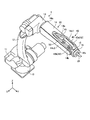
- FIG. 1 is a side view showing a robot according to the present embodiment.
- FIG. 2 is a perspective view of the robot shown in FIG. 3 is a schematic cross-sectional view taken along line III-III in FIG.
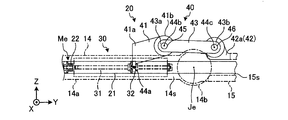
- FIG. 4A is a schematic side view schematically showing the vicinity of the connection portion of the first and second wrist portions shown in FIG. 1.
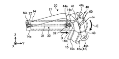
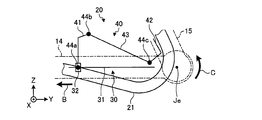
- FIG. 4B is a schematic side view schematically showing the vicinity of the connection portion of the first and second wrist portions shown in FIG. 4A.
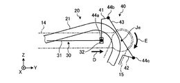
- FIG. 4C is a schematic side view schematically showing the vicinity of the connection portion of the first and second wrist portions shown in FIG. 4A.
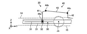
- FIG. 5A is a schematic side view showing a modification of the link mechanism of the robot according to the present embodiment and schematically showing the vicinity of the connection portion of the first and second wrist portions.
- FIG. 5B is a schematic side view schematically showing the vicinity of the connection portion of the first and second wrist portions shown in FIG. 5A.
- FIG. 5C is a schematic side view schematically showing the vicinity of the connection portion of the first and second wrist portions shown in FIG. 5A.
- FIG. 1 is a side view showing a robot according to the present embodiment
- FIG. 2 is a perspective view of the robot shown in FIG.
- FIG. 1 shows a Z-axis in which the vertical upward direction is the positive direction and a vertical downward direction is the negative direction, the left-right direction on the paper surface is the Y-axis, and the forward direction from the back of the paper surface is the X-axis.
- a three-dimensional orthogonal coordinate system is illustrated. Such an orthogonal coordinate system may be shown in other drawings including those shown in FIG.
- X-axis direction means the axis and the Z-axis direction, and is not limited to the expressed direction.
- the robot 1 is an articulated robot having a plurality of link members and a plurality of rotation axes (joint axes) Ja to Jf for connecting the link members, as well shown in FIG.
- the robot 1 includes, as link members, a base 10, a turning unit 11, a lower arm 12, an upper arm 13, a first wrist (first link member) 14, and a second wrist (first link). 2 link members) 15 and a third wrist portion 16, which are rotatably connected to each other.
- the swivel unit 11 is connected to the base 10 so as to be rotatable about the rotation axis Ja.
- the lower arm 12 is connected to the revolving part 11 so as to be rotatable about a rotation axis Jb perpendicular to the rotation axis Ja, and the upper arm 13 is connected to the rotation axis Jc parallel to the rotation axis Jb with respect to the lower arm 12. It is connected so that it can rotate around.
- the first wrist portion 14 is formed in an elongated shape, and specifically has a shape that extends along the Y-axis direction.
- the first wrist portion 14 has a base end 14a connected to the upper arm 13 so as to be rotatable about a rotation axis Jd perpendicular to the rotation axis Jc.
- the rotation axis Jd is parallel to the extending direction of the first wrist portion 14 (specifically, for example, the Y-axis direction).
- the second wrist portion 15 is connected to the tip 14b of the first wrist portion 14, and is connected to the first wrist portion 14 so as to be rotatable around a rotation axis Je perpendicular to the rotation axis Jd.
- the second wrist portion 15 is connected to be rotatable about a rotation axis Je perpendicular to the extending direction of the first wrist portion 14.
- the third wrist portion 16 is connected to the second wrist portion 15 so as to be rotatable around a rotation axis Jf perpendicular to the rotation axis Je.
- the robot 1 further includes actuators Ma to Mf for rotating the swivel unit 11, the lower arm 12, the upper arm 13, and the first to third wrist parts 14, 15, and 16 (in FIG. 1, any actuator Ma to Mf). (Not shown).
- Each of the actuators Ma to Mf is specifically a servo motor, for example.
- the actuators Ma to Mf are servo motors, the present invention is not limited thereto, and may be other types of motors such as a hydraulic motor. In the following, the actuator is expressed as “motor”.
- the motor Ma is connected to the turning unit 11 and rotationally drives the turning unit 11.
- the motor Mb is connected to the lower arm 12 to rotationally drive the lower arm 12, and the motor Mc is connected to the upper arm 13 to rotationally drive the upper arm 13.
- the motor Md is connected to the first wrist portion 14 and rotationally drives the first wrist portion 14.
- the motor Me is attached to the first wrist portion 14.
- the motor Me is connected to the second wrist portion 15 via the power transmission mechanism 20 and rotationally drives the second wrist portion 15.
- the configuration of the power transmission mechanism 20 in this embodiment will be described in detail later.
- the motor Mf is connected to the third wrist portion 16 and rotationally drives the third wrist portion 16.
- a signal indicating an operation command is input to the motors Ma to Mf from a control device (not shown), and the operation is controlled based on the signal. Further, an end effector (not shown) (for example, an arc welding torch) is attached to the third wrist portion 16.
- the robot 1 performs predetermined work with the end effector by controlling the operations of the motors Ma to Mf by the control device. Specifically, for example, the position and angle of the torch are appropriately changed while welding is performed. Arc welding is performed with the torch approaching the object.
- an arc welding torch is provided as an end effector, but this is an example and is not limited. That is, for example, a hand for gripping a workpiece or a suction portion for sucking and holding a workpiece may be provided as an end effector, and the robot 1 may perform other operations such as a workpiece transfer operation.
- the robot 1 further includes a cable 21 connected to the end effector.
- the cable 21 is a conduit cable including, for example, an electric wire for supplying power to the end effector, a torch wire serving as a filler material for arc welding, and the like.
- a configuration in which the above-described cable 21 can be incorporated in the first and second wrist portions 14 and 15 is preferable.
- a configuration in which the first to third wrist portions 14 to 16 are formed hollow and the cable 21 is disposed in the hollow portion is preferable.
- a motor Me, a power transmission mechanism 20 and the like are also arranged near the first wrist portion 14. Therefore, for example, if the cable 21, the motor Me, and the power transmission mechanism 20 are all built in the first wrist portion 14, the hollow portion of the first wrist portion 14 is enlarged to provide a space. There is a possibility that the robot 1 cannot be miniaturized.
- the robot 1 by arranging a part of the power transmission mechanism 20 outside the first and second wrist portions 14 and 15, the first and second wrist portions which are link members.
- the space of the hollow portions 14 and 15 was secured, and the size was reduced.
- FIG. 3 is a schematic cross-sectional view taken along the line III-III of FIG. 1, and is an enlarged cross-sectional top view schematically showing the vicinity of the first and second wrist portions 14 and 15 shown in FIG.
- the first and second wrist portions 14 and 15 are cut surfaces when cut along the XY plane including the rotation axis Je.
- the first wrist portion 14 is formed so that the tip end 14b side is bifurcated.
- the first wrist portion 14 includes a plurality (specifically, two) of side wall portions 14c1 and 14c2, and the two side wall portions 14c1 and 14c2 are arranged to face each other, so that the tip 14b side is bifurcated. Formed.
- the first wrist portion 14 is formed hollow.
- the hollow portion of the first wrist portion 14 is indicated by reference numeral 14s.
- the upper and lower surfaces in the Z-axis direction are partially opened toward the outside.
- the second wrist portion 15 is pivotally supported from both sides by the two side wall portions 14c1 and 14c2 described above on the tip 14b side of the first wrist portion 14, and is supported by a so-called both-end supported structure. Further, as shown in FIG. 3, the second wrist portion 15 is also formed with a hollow portion 15 s in the same manner as the first wrist portion 14. Similarly, the hollow part 16s is formed also in the 3rd wrist part 16 (refer FIG. 2).
- the cable 21 is disposed from the hollow portion 14s of the first wrist portion 14 to the hollow portion 15s of the second wrist portion 15, and then passes through the hollow portion 16s of the third wrist portion 16 to the end effector. Connected to.
- the cable 21 is disposed in the hollow portions 14s to 16s of the first to third wrist portions 14 to 16, so that the first to third wrist portions 14 to 16 are arranged. 16 built in.
- the robot 1 can be reduced in size as compared with the configuration in which the cable 21 is exposed to the outside. Further, by incorporating the cable 21, the cable 21 can be protected from, for example, an impact received from the outside.
- FIG. 4A is a schematic side view schematically showing the vicinity of the connection portion of the first and second wrist portions 14 and 15 shown in FIG. In FIG. 4A, only the components necessary for the description of the power transmission mechanism 20 are schematically shown.
- the power transmission mechanism 20 includes a linear motion drive unit 30 and a link mechanism 40.
- the linear drive unit 30 is attached to the first wrist portion 14 at a position offset from the rotation axis Je to the base end 14a side (the negative direction side in the Y axis).
- the linear motion drive unit 30 is attached to one of the two side wall portions 14 c 1 and 14 c 2 of the first wrist portion 14, for example, the side wall portion 14 c 1, and is built in the first wrist portion 14. .
- the linear motion drive unit 30 is specifically a ball screw mechanism, for example.
- the linear drive unit 30 includes a screw shaft 31 and a nut portion 32.
- One end of the screw shaft 31 is connected to the output shaft 22 of the motor Me and is rotatably supported.
- the nut portion 32 is screwed to the screw shaft 31 via a ball (not shown).
- the linear drive part 30 is comprised so that the nut part 32 may carry out a linear motion along the extending
- the linear drive unit 30 is a ball screw mechanism, but this is an example and is not limited.
- the linear motion drive unit 30 may be configured to have a member that moves linearly, and may be another type of mechanism such as a hydraulic cylinder or a pneumatic cylinder.
- the link mechanism 40 connects the linear motion drive unit 30 and the second wrist unit 15 described above. More specifically, the link mechanism 40 includes a drive side link 41, a driven side link 42, and an intermediate link 43.
- the drive-side link 41 is fixed with one end 41 a connected to the nut portion 32 of the linear motion drive unit 30.
- a connection position between the drive side link 41 and the linear motion drive unit 30 is referred to as a “first connection position” and is denoted by reference numeral 44a (see FIG. 4A).
- the drive side link 41 is formed in a long shape and extends from the first connection position 44 a toward the tip 14 b of the first wrist portion 14.
- the driven side link 42 includes a pair of connecting members 42a and 42b.
- the connecting member 42b is removed and only the connecting member 42a is shown. Both the connecting members 42a and 42b of the driven side link 42 are connected and fixed to the second wrist portion 15.
- the intermediate link 43 is formed in a long shape and is substantially linear.
- the intermediate link 43 has one end 43 a rotatably connected to the drive side link 41 and the other end 43 b rotatably connected to the driven side link 42.
- an insertion hole is formed in one end 43a of the intermediate link 43 and the other end 41b of the drive side link 41, and a shaft 45 supported rotatably is inserted in the inserted insertion hole. .
- the one end 43a of the intermediate link 43 and the drive side link 41 are rotatably connected via the shaft 45.
- the connection position between the intermediate link 43 and the drive side link 41 is referred to as a “second connection position 44b” (see FIG. 4A).
- insertion holes are formed in the other end 43b of the intermediate link 43 and the connecting members 42a and 42b of the driven side link 42, respectively.
- a shaft 46 that is rotatably supported is inserted into the insertion hole formed in the connecting member 42a and the intermediate link 43, and the insertion hole formed in the connection member 42b and the intermediate link 43 is rotatable.
- the shaft 47 supported by is inserted.
- the other end 43 b of the intermediate link 43 and the driven side link 42 are rotatably connected via the shafts 46 and 47.
- the connection position between the intermediate link 43 and the driven link 42 is referred to as a “third connection position 44c” (see FIG. 4A).
- the drive side link 41 is shaped to extend from the first connection position 44a toward the tip 14b of the first wrist portion 14. Therefore, the second and third connection positions 44b and 44c are both positioned at the tip 14b of the first wrist portion 14 rather than the first connection position 44a. Thereby, in the link mechanism 40, a space for allowing the cable 21 to be bent to escape can be secured. This will be described in detail later.
- the link mechanism 40 configured as described above has at least a portion of the first wrist portion 14 and the first wrist portion 14 when viewed from the direction of the rotation axis Je, that is, when viewed in the X-axis direction. It is arranged outside the outer edge of the second wrist portion 15. Further, the link mechanism 40 is positioned above in the vertical direction (Z-axis direction) with respect to the first wrist portion 14 and the second wrist portion 15.
- the link mechanism 40 is configured not to be disposed in the hollow portions 14s and 15s of the first and second wrist portions 14 and 15, that is, not to be incorporated in the first and second wrist portions 14 and 15. .
- a space for arranging the cable 21 and the linear motion drive unit 30 may be secured, and the link mechanism 40 is incorporated. You can make it smaller by not doing it.
- the link mechanism 40 which is a part of the power transmission mechanism 20, is secured to the first and second wrist portions 14 and 15 while securing a space for arranging the cables 21 and the like. By arranging it outside the second wrist parts 14 and 15, it is possible to reduce the size.
- the width dimension W in the vicinity of the rotation axis Je becomes large.
- the link mechanism 40 by arranging the link mechanism 40 as described above, the width dimension W near the rotation axis Je can be reduced, and as a result, the robot 1 can be reduced in size.
- the link mechanism 40 has outer edges of the first wrist portion 14 and the second wrist portion 15 when viewed from the direction perpendicular to the rotation axis Je, that is, when viewed in the Z-axis direction. It is arranged more inside. Thereby, the width dimension W of the robot 1 near the rotation axis Je can be further reduced, and the robot 1 can be reliably downsized.
- the link mechanism 40 is positioned above the first and second wrist portions 14 and 15 in the vertical direction, the space above the first and second wrist portions 14 and 15 is effectively used. can do.
- the robot 1 further includes a guide unit 50.
- the guide part 50 is attached to the other of the two side wall parts 14 c 1 and 14 c 2 of the first wrist part 14, for example, the side wall part 14 c 2, and is built in the first wrist part 14.
- the guide part 50 is attached to the first wrist part 14 at a position facing the linear motion drive part 30. Therefore, the cable 21 is disposed between the linear drive unit 30 and the guide unit 50.
- the guide unit 50 includes a guide rail unit 51, a slide unit 52, and a guide connecting member 53.
- the guide rail portion 51 is installed so as to extend along the extending direction of the first wrist portion 14.
- the slide part 52 is connected to the guide rail part 51 so as to be slidable (slidable), so that it can be linearly moved along the guide rail part 51.
- the guide connecting member 53 has one end 53 a connected to the guide rail portion 51 and fixed thereto, while the other end 53 b is rotatably connected to one end 43 a of the intermediate link 43.
- an insertion hole is formed in the other end 53 b of the guide connecting member 53.
- the shaft 54 that is rotatably supported is inserted through the insertion hole of the guide connecting member 53 and the insertion hole of the one end 43 a of the intermediate link 43.
- the shaft 54 is inserted into the insertion hole of the one end 43a of the intermediate link 43 from the side opposite to the side through which the shaft 45 is inserted, specifically, from the positive side of the X axis toward the negative side. .
- the guide connecting member 53 and the one end 43a of the intermediate link 43 are rotatably connected via the shaft 54.
- the shaft 45 and the shaft 54 inserted through the one end 43a of the intermediate link 43 are coaxial.
- the guide part 50 functions as a guide that causes the drive side link 41 and the like to stably move linearly.
- the drive side link 41 of the link mechanism 40 and the guide connecting member 53 of the guide portion 50 are viewed from a direction perpendicular to the rotation axis Je, that is, viewed in the Z-axis direction.
- the cable 21 is formed so as not to overlap.
- the intermediate link 43 of the link mechanism 40 is disposed so as to overlap the cable 21 when viewed from a direction perpendicular to the rotation axis Je, that is, when viewed in the Z-axis direction.
- the cable 21 comes into contact with the intermediate link 43 depending on the bent state.
- the cable 21 is not further bent due to the contact with the intermediate link 43, and therefore, the cable 21 can be prevented from being ramped up.
- the intermediate link 43 is arranged so as to overlap upward in the Z-axis direction of the cable 21.
- the cable 21 can be protected from an impact from above in the Z-axis direction.
- the link mechanism 40 configured as described above drives the second wrist 15 to rotate according to the linear motion of the linear motion drive unit 30.
- the operation of the link mechanism 40 will be described with reference to FIGS. 4A to 4C.
- FIG. 4B and 4C are schematic side views similar to FIG. 4A, schematically showing the vicinity of the connection portion of the first and second wrist portions 14 and 15.
- FIG. 4A is schematically showing the vicinity of the connection portion of the first and second wrist portions 14 and 15.
- the state shown in FIG. 4A is referred to as “reference position state” in this specification.
- the second wrist portion 15 is not rotated with respect to the first wrist portion 14, more specifically, the hollow portion 14s of the first wrist portion 14 and the second wrist portion.
- the 15 hollow portions 15 s communicate with each other along the extending direction (Y-axis direction) of the first wrist portion 14.
- the cable 21 disposed in the hollow portions 14s and 15s is substantially straight along the extending direction in the reference position state, in other words, is not bent.
- the nut portion 32 of the linear drive unit 30 is assumed to be positioned approximately in the middle of the screw shaft 31, for example.
- the nut portion 32 of the linear motion drive unit 30 is linearly moved toward the base end 14a side of the first wrist portion 14 as indicated by an arrow B by the output of the motor Me.
- the link mechanism 40 is moved in the negative direction of the Y axis according to the linear motion of the linear drive unit 30.
- the intermediate link 43 is rotated clockwise with respect to the drive side link 41 around the second connection position 44b, and the driven side link 42 is third with respect to the intermediate link 43. It is rotated counterclockwise around the connection position 44c.
- the cable 21 When the cable 21 is in the counterclockwise position state, the cable 21 is bent so as to protrude in a direction away from the link mechanism 40. However, since the lower surface of the hollow portion 14s of the first wrist portion 14 is opened as described above, the bent cable 21 can be released from the opening of the hollow portion 14s. That is, the bent cable 21 does not interfere with surrounding members such as the first wrist portion 14.
- the nut portion 32 of the linear motion drive unit 30 is linearly moved toward the tip 14b side of the first wrist portion 14 as indicated by an arrow D by the output of the motor Me.
- the link mechanism 40 is moved in the positive direction of the Y axis according to the linear motion of the linear drive unit 30.
- the intermediate link 43 is rotated clockwise with respect to the drive side link 41 around the second connection position 44b, and the driven side link 42 is also third with respect to the intermediate link 43. It is rotated clockwise around the connection position 44c.
- the cable 21 When the cable 21 is in the clockwise position state, the cable 21 is bent so as to protrude in the direction in which the link mechanism 40 is disposed (upper side in FIG. 4C). However, since the hollow portion 14s of the first wrist portion 14 is also opened at the upper surface, the bent cable 21 can escape from the opening of the hollow portion 14s. That is, the bent cable 21 does not interfere with surrounding members such as the first wrist portion 14.
- the cable 21 when viewed from the direction of the rotation axis Je, the cable 21 is between the first connection position 44a and the second connection position 44b and between the first connection position 44a and the third connection position 44c. It is bent while being positioned. Thereby, the 2nd wrist part 15 can be reliably rotationally driven clockwise centering on the rotating shaft Je.
- both the second and third connection positions 44b and 44c are It will be located in the front-end
- the cable 21 when the cable 21 is bent so as to protrude toward the intermediate link 43, the cable 21 may come into contact with the intermediate link 43 depending on the bent state. At this time, since the cable 21 is prevented from further bending by the intermediate link 43, the cable 21 can be prevented from being ramped up.
- the bent cable 21 comes into direct contact with the intermediate link 43, but the present invention is not limited to this. That is, as shown by an imaginary line in FIG. 4C, the intermediate link 43 may include a rotating body (roller) 60 that can contact the cable 21, and the cable 21 may contact the rotating body 60.
- the intermediate link 43 may include a rotating body (roller) 60 that can contact the cable 21, and the cable 21 may contact the rotating body 60.
- a plurality of (for example, three) rotating bodies 60 are connected to appropriate positions of the intermediate link 43 so as to be rotatable.
- the number of rotating bodies 60 is an example and is not limited, and may be one, two, four, or more depending on the specifications of the cable 21 and the like.
- the intermediate link 43 includes the rotating body 60, it is possible to avoid the cable 21 and the intermediate link 43 from coming into direct contact with each other, and thus the cable 21 and the intermediate link 43 may be reliably protected.
- the present embodiment includes the first wrist portion 14, the second wrist portion 15, the linear motion drive portion 30, and the link mechanism 40.
- the first wrist portion 14 is hollow.
- the second wrist portion 15 is formed in a hollow shape, and is connected to the tip 14b of the first wrist portion 14 so as to be rotatable about a rotation axis Je perpendicular to the extending direction of the first wrist portion 14.
- the linear motion drive unit 30 is attached to a position offset from the rotation axis Je to the base end 14a side in the first wrist unit 14, and linearly moves along the extending direction.
- the link mechanism 40 is disposed outside the outer edges of the first and second wrist parts 14 and 15 when viewed from the direction of the rotation axis Je, and is connected to the linear drive unit 30 and the second wrist part 15.
- the second wrist portion 15 is rotationally driven in accordance with the linear motion of the linear motion drive portion 30.
- the robot 1 it is possible to reduce the size while securing the space of the hollow portions 14s and 15s of the first and second wrist portions 14 and 15 which are link members.
- the drive side link 41, the driven side link 42, and the intermediate link 43 of the link mechanism 40 are not limited to the shapes shown in FIGS. 4A to 4C. That is, the link mechanism 40 may have any shape as long as the second wrist portion 15 can be rotationally driven while allowing the bent cable 21 to escape.
- FIGS. 5A to 5C are schematic side views showing the modification of the link mechanism 40 in the robot 1 and in the vicinity of the connection portion between the first and second wrist portions 14 and 15.
- FIG. FIGS. 5A to 5C are schematic side views similar to FIGS. 4A to 4C, but are very schematically shown, such as the drive side link 41, the driven side link 42, etc. being shown by straight lines.
- the second connection position 44b is on the negative side of the Y axis and on the positive side of the Z axis, and the third connection position 44c.
- the shape of the drive side link 41, the driven side link 42, and the intermediate link 43 was changed so that is on the positive side of the Z axis.
- the power transmission mechanism 20 that connects the motor Me and the second wrist 15 is provided with the link mechanism 40.
- the present invention is not limited to this. That is, for example, the power transmission mechanism that connects the motor Ma and the turning portion 11, the motor Mb and the lower arm 12, the motor Mc and the upper arm 13, the motor Md and the first wrist portion 14, and the motor Mf and the third wrist portion 16.
- the link mechanism 40 as described above may be used.
- the intermediate link 43 of the link mechanism 40 is configured to have a linear shape
- the present invention is not limited to this. That is, in order to avoid interference with the cable 21 that bends, the intermediate link 43 may have a substantially L shape, for example, when viewed in the X-axis direction, and may protrude in the positive direction of the Z-axis.
- the robot 1 has been described as a 6-axis robot, the present invention is not limited to this configuration, and a robot other than the 6-axis configuration, for example, a 7-axis or 8-axis robot can be used.
Landscapes
- Engineering & Computer Science (AREA)
- Robotics (AREA)
- Mechanical Engineering (AREA)
- Manipulator (AREA)
Abstract
Le robot (1) de l'invention comprend une première unité de poignet (14), une seconde unité de poignet (15), une unité d'entraînement linéaire (30), et un mécanisme de liaison (40). La première unité de poignet est formée creuse. La seconde unité de poignet est formée creuse et reliée au bout (14b) de la pointe de la première unité de poignet de manière à tourner centrée autour d'un axe de rotation (Je) perpendiculaire à la direction d'extension de la première unité de poignet. L'unité d'entraînement linéaire est fixée à une position décalée de l'extrémité de base (14a) de la première unité de poignet à partir de l'axe de rotation, et effectue un mouvement linéaire le long de la direction d'extension. Le mécanisme de liaison est disposé vers l'extérieur du bord extérieur de la première et de la seconde unité de poignet, vu dans la direction de l'axe de rotation. il est raccordé à l'unité d'entraînement linéaire et à la seconde unité de poignet, et entraîne en rotation la seconde unité de poignet de concert avec le mouvement linéaire de l'unité d'entraînement linéaire.
Priority Applications (1)
| Application Number | Priority Date | Filing Date | Title |
|---|---|---|---|
| PCT/JP2013/067714 WO2014207872A1 (fr) | 2013-06-27 | 2013-06-27 | Robot |
Applications Claiming Priority (1)
| Application Number | Priority Date | Filing Date | Title |
|---|---|---|---|
| PCT/JP2013/067714 WO2014207872A1 (fr) | 2013-06-27 | 2013-06-27 | Robot |
Publications (1)
| Publication Number | Publication Date |
|---|---|
| WO2014207872A1 true WO2014207872A1 (fr) | 2014-12-31 |
Family
ID=52141272
Family Applications (1)
| Application Number | Title | Priority Date | Filing Date |
|---|---|---|---|
| PCT/JP2013/067714 Ceased WO2014207872A1 (fr) | 2013-06-27 | 2013-06-27 | Robot |
Country Status (1)
| Country | Link |
|---|---|
| WO (1) | WO2014207872A1 (fr) |
Cited By (2)
| Publication number | Priority date | Publication date | Assignee | Title |
|---|---|---|---|---|
| WO2018112102A1 (fr) * | 2016-12-15 | 2018-06-21 | Boston Dynamics, Inc. | Actionneur à vis pour robot marcheur |
| KR20250090872A (ko) * | 2023-12-13 | 2025-06-20 | 주식회사 유진엠에스 | 로봇용 핸드 |
Citations (9)
| Publication number | Priority date | Publication date | Assignee | Title |
|---|---|---|---|---|
| JPS60242986A (ja) * | 1985-04-22 | 1985-12-02 | 株式会社日立製作所 | 工業用多関節形ロボツト |
| JPS6189489U (fr) * | 1984-11-14 | 1986-06-11 | ||
| JPH03245987A (ja) * | 1990-02-26 | 1991-11-01 | Fanuc Ltd | 産業用ロボットの手首ツール |
| JPH0451310B2 (fr) * | 1985-08-19 | 1992-08-18 | Mitsubishi Electric Corp | |
| JPH10217158A (ja) * | 1997-01-30 | 1998-08-18 | Sony Corp | ロボツト装置 |
| JPH11123688A (ja) * | 1997-10-24 | 1999-05-11 | Nachi Fujikoshi Corp | 産業用ロボットのアーム構造 |
| JP2003326491A (ja) * | 2002-05-08 | 2003-11-18 | Denso Wave Inc | ロボット及びツール取付アタッチメント |
| JP2005169602A (ja) * | 2003-12-15 | 2005-06-30 | Thk Co Ltd | ロボット関節構造 |
| US8091448B2 (en) * | 2009-03-16 | 2012-01-10 | Korea Advanced Institute Of Science And Technology | Manipulator with distributed actuation mechanism |
-
2013
- 2013-06-27 WO PCT/JP2013/067714 patent/WO2014207872A1/fr not_active Ceased
Patent Citations (9)
| Publication number | Priority date | Publication date | Assignee | Title |
|---|---|---|---|---|
| JPS6189489U (fr) * | 1984-11-14 | 1986-06-11 | ||
| JPS60242986A (ja) * | 1985-04-22 | 1985-12-02 | 株式会社日立製作所 | 工業用多関節形ロボツト |
| JPH0451310B2 (fr) * | 1985-08-19 | 1992-08-18 | Mitsubishi Electric Corp | |
| JPH03245987A (ja) * | 1990-02-26 | 1991-11-01 | Fanuc Ltd | 産業用ロボットの手首ツール |
| JPH10217158A (ja) * | 1997-01-30 | 1998-08-18 | Sony Corp | ロボツト装置 |
| JPH11123688A (ja) * | 1997-10-24 | 1999-05-11 | Nachi Fujikoshi Corp | 産業用ロボットのアーム構造 |
| JP2003326491A (ja) * | 2002-05-08 | 2003-11-18 | Denso Wave Inc | ロボット及びツール取付アタッチメント |
| JP2005169602A (ja) * | 2003-12-15 | 2005-06-30 | Thk Co Ltd | ロボット関節構造 |
| US8091448B2 (en) * | 2009-03-16 | 2012-01-10 | Korea Advanced Institute Of Science And Technology | Manipulator with distributed actuation mechanism |
Cited By (6)
| Publication number | Priority date | Publication date | Assignee | Title |
|---|---|---|---|---|
| WO2018112102A1 (fr) * | 2016-12-15 | 2018-06-21 | Boston Dynamics, Inc. | Actionneur à vis pour robot marcheur |
| CN110072677A (zh) * | 2016-12-15 | 2019-07-30 | 波士顿动力公司 | 用于有腿机器人的螺旋致动器 |
| US11754155B2 (en) | 2016-12-15 | 2023-09-12 | Boston Dynamics, Inc. | Screw actuator for a legged robot |
| US12123481B2 (en) | 2016-12-15 | 2024-10-22 | Boston Dynamics, Inc. | Screw actuator for a legged robot |
| KR20250090872A (ko) * | 2023-12-13 | 2025-06-20 | 주식회사 유진엠에스 | 로봇용 핸드 |
| KR102927194B1 (ko) | 2023-12-13 | 2026-02-13 | 주식회사 유진엠에스 | 로봇용 핸드 |
Similar Documents
| Publication | Publication Date | Title |
|---|---|---|
| CN103934831B (zh) | 机器人 | |
| CN105307824B (zh) | 具有设置在悬臂上的驱动器布局的工业机器人 | |
| CN102395449B (zh) | 用于机器人臂的设备 | |
| CN102085659B (zh) | 空间可控五自由度十二杆焊接机器人机构 | |
| JP5499647B2 (ja) | ロボット及びロボットシステム | |
| KR101323918B1 (ko) | 다관절 머니퓰레이터 | |
| US10821598B2 (en) | Robot and robot system | |
| CN103934832B (zh) | 机器人 | |
| CN103203741B (zh) | 一种三自由度并联机器人机构 | |
| KR102206699B1 (ko) | 산업용 로봇 | |
| CN110234471B (zh) | 弯曲臂机器人 | |
| US20120266712A1 (en) | Robot | |
| US11130225B2 (en) | Working device and double-arm type working device | |
| CN201881377U (zh) | 空间可控五自由度十二杆焊接机器人机构 | |
| JP2015104764A (ja) | アーム機構 | |
| JP5423910B1 (ja) | ロボット | |
| CN105121101B (zh) | 操纵器结构 | |
| JP6688204B2 (ja) | リンク式多関節ロボット | |
| JP4632065B2 (ja) | ロボット | |
| CN102101291B (zh) | 机械手臂 | |
| JP6182064B2 (ja) | ロボット | |
| JP4133843B2 (ja) | 産業用ロボット | |
| JP2019038050A (ja) | ロボット | |
| CN109996655A (zh) | 机器人的关节构造体 | |
| JP2025018822A (ja) | ロボットリスト |
Legal Events
| Date | Code | Title | Description |
|---|---|---|---|
| 121 | Ep: the epo has been informed by wipo that ep was designated in this application |
Ref document number: 13888150 Country of ref document: EP Kind code of ref document: A1 |
|
| NENP | Non-entry into the national phase |
Ref country code: DE |
|
| NENP | Non-entry into the national phase |
Ref country code: JP |
|
| 122 | Ep: pct application non-entry in european phase |
Ref document number: 13888150 Country of ref document: EP Kind code of ref document: A1 |