WO2014207980A1 - Système de gestion de transport pour véhicules alimentés par batterie - Google Patents
Système de gestion de transport pour véhicules alimentés par batterie Download PDFInfo
- Publication number
- WO2014207980A1 WO2014207980A1 PCT/JP2014/002432 JP2014002432W WO2014207980A1 WO 2014207980 A1 WO2014207980 A1 WO 2014207980A1 JP 2014002432 W JP2014002432 W JP 2014002432W WO 2014207980 A1 WO2014207980 A1 WO 2014207980A1
- Authority
- WO
- WIPO (PCT)
- Prior art keywords
- vehicle
- battery
- power
- route
- stored
- Prior art date
- Legal status (The legal status is an assumption and is not a legal conclusion. Google has not performed a legal analysis and makes no representation as to the accuracy of the status listed.)
- Ceased
Links
Images





Classifications
-
- G—PHYSICS
- G01—MEASURING; TESTING
- G01C—MEASURING DISTANCES, LEVELS OR BEARINGS; SURVEYING; NAVIGATION; GYROSCOPIC INSTRUMENTS; PHOTOGRAMMETRY OR VIDEOGRAMMETRY
- G01C21/00—Navigation; Navigational instruments not provided for in groups G01C1/00 - G01C19/00
- G01C21/26—Navigation; Navigational instruments not provided for in groups G01C1/00 - G01C19/00 specially adapted for navigation in a road network
- G01C21/34—Route searching; Route guidance
- G01C21/3453—Special cost functions, i.e. other than distance or default speed limit of road segments
- G01C21/3469—Fuel consumption; Energy use; Emission aspects
-
- G—PHYSICS
- G06—COMPUTING OR CALCULATING; COUNTING
- G06Q—INFORMATION AND COMMUNICATION TECHNOLOGY [ICT] SPECIALLY ADAPTED FOR ADMINISTRATIVE, COMMERCIAL, FINANCIAL, MANAGERIAL OR SUPERVISORY PURPOSES; SYSTEMS OR METHODS SPECIALLY ADAPTED FOR ADMINISTRATIVE, COMMERCIAL, FINANCIAL, MANAGERIAL OR SUPERVISORY PURPOSES, NOT OTHERWISE PROVIDED FOR
- G06Q10/00—Administration; Management
- G06Q10/04—Forecasting or optimisation specially adapted for administrative or management purposes, e.g. linear programming or "cutting stock problem"
- G06Q10/047—Optimisation of routes or paths, e.g. travelling salesman problem
-
- G—PHYSICS
- G06—COMPUTING OR CALCULATING; COUNTING
- G06Q—INFORMATION AND COMMUNICATION TECHNOLOGY [ICT] SPECIALLY ADAPTED FOR ADMINISTRATIVE, COMMERCIAL, FINANCIAL, MANAGERIAL OR SUPERVISORY PURPOSES; SYSTEMS OR METHODS SPECIALLY ADAPTED FOR ADMINISTRATIVE, COMMERCIAL, FINANCIAL, MANAGERIAL OR SUPERVISORY PURPOSES, NOT OTHERWISE PROVIDED FOR
- G06Q10/00—Administration; Management
- G06Q10/08—Logistics, e.g. warehousing, loading or distribution; Inventory or stock management
-
- G—PHYSICS
- G06—COMPUTING OR CALCULATING; COUNTING
- G06Q—INFORMATION AND COMMUNICATION TECHNOLOGY [ICT] SPECIALLY ADAPTED FOR ADMINISTRATIVE, COMMERCIAL, FINANCIAL, MANAGERIAL OR SUPERVISORY PURPOSES; SYSTEMS OR METHODS SPECIALLY ADAPTED FOR ADMINISTRATIVE, COMMERCIAL, FINANCIAL, MANAGERIAL OR SUPERVISORY PURPOSES, NOT OTHERWISE PROVIDED FOR
- G06Q50/00—Information and communication technology [ICT] specially adapted for implementation of business processes of specific business sectors, e.g. utilities or tourism
- G06Q50/06—Energy or water supply
-
- G—PHYSICS
- G06—COMPUTING OR CALCULATING; COUNTING
- G06Q—INFORMATION AND COMMUNICATION TECHNOLOGY [ICT] SPECIALLY ADAPTED FOR ADMINISTRATIVE, COMMERCIAL, FINANCIAL, MANAGERIAL OR SUPERVISORY PURPOSES; SYSTEMS OR METHODS SPECIALLY ADAPTED FOR ADMINISTRATIVE, COMMERCIAL, FINANCIAL, MANAGERIAL OR SUPERVISORY PURPOSES, NOT OTHERWISE PROVIDED FOR
- G06Q50/00—Information and communication technology [ICT] specially adapted for implementation of business processes of specific business sectors, e.g. utilities or tourism
- G06Q50/40—Business processes related to the transportation industry
-
- Y—GENERAL TAGGING OF NEW TECHNOLOGICAL DEVELOPMENTS; GENERAL TAGGING OF CROSS-SECTIONAL TECHNOLOGIES SPANNING OVER SEVERAL SECTIONS OF THE IPC; TECHNICAL SUBJECTS COVERED BY FORMER USPC CROSS-REFERENCE ART COLLECTIONS [XRACs] AND DIGESTS
- Y04—INFORMATION OR COMMUNICATION TECHNOLOGIES HAVING AN IMPACT ON OTHER TECHNOLOGY AREAS
- Y04S—SYSTEMS INTEGRATING TECHNOLOGIES RELATED TO POWER NETWORK OPERATION, COMMUNICATION OR INFORMATION TECHNOLOGIES FOR IMPROVING THE ELECTRICAL POWER GENERATION, TRANSMISSION, DISTRIBUTION, MANAGEMENT OR USAGE, i.e. SMART GRIDS
- Y04S10/00—Systems supporting electrical power generation, transmission or distribution
- Y04S10/50—Systems or methods supporting the power network operation or management, involving a certain degree of interaction with the load-side end user applications
Definitions
- the present invention relates to a transportation management system for battery powered vehicles.
- Fig. 1 schematically illustrates a configuration of a system including the managing system according to an embodiment.
- Fig. 2 schematically illustrates a configuration of the managing system according to the embodiment.
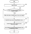
- Fig. 3 is a flowchart illustrating an example of a calculation process by a first calculation part of the managing system according to the embodiment.
- Fig.4 is a flowchart illustrating an example of a calculation process by a second calculation part of the managing system according to the embodiment.
- Fig. 5 is a flowchart illustrating an example of a calculation process by a third calculation part of the managing system according to the embodiment.
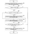
- Fig. 6 is a flowchart illustrating an example of a calculation process by a setting part of the managing system according to the embodiment.
- Fig. 7 is a flowchart illustrating an example of a calculation process by an update part of the managing system according to the embodiment.
- Fig. 8 is a flowchart illustrating an example of a calculation process by an assignment part of the managing system according to
- a method for managing a transportation service along a plurality of routes with a plurality of vehicles includes allocating a vehicle to a first route, calculating an amount of power to be used by the vehicle while the vehicle is providing transportation service along the first route, determining a range of power to be stored in a battery of the vehicle based on at least a deterioration degree of the battery, and reallocating the vehicle to a second route based on the calculated amount of power and the determined range of power to be stored in the battery of the vehicle.
- a vehicle 1 is an electric vehicle (battery-powered vehicle) provided with a battery that can be repeatedly charged (a secondary battery is not illustrated) and a vehicle drive device such as a motor powered using the electricity stored in the battery.
- the vehicle 1 is, for example, a bus (a route bus), a vehicle of light rail transit (LRT), or the like.
- each route R of the vehicle 1 is set so as to connect charge spots 10 (charge station, charge terminal, or charge device).
- a route R can be set as a route connecting two different charge spots 10, or it can be set as a route that begins from one charge spot 10 and returns to the same charge spot 10.
- Each of the charge spots 10 is equipped with at least one charge device (charger not illustrated).
- Each of the charge spots 10 can be in a terminal of the vehicle 1, a stop, a station, an office, a garage, and the like.
- the route R is a unit (section) to which at least one vehicle 1 is assigned.
- a service schedule (time schedule, timetable, or diagram) of the vehicles 1 on a plurality of routes R is determined beforehand.
- a managing system 100 (a managing system for managing a transportation service of the battery-powered vehicle) is configured by at least one computer. The managing system 100 assigns at least one of the vehicles 1 to each route R (makes plans) before the vehicle 1 runs along the assigned route R so that the vehicle 1 runs along the assigned route R in accordance with the service schedule. When the electricity stored in the battery of the vehicle 1 runs out, the vehicle 1 cannot run.
- the managing system 100 when assigning the vehicle 1 to each routes R, the managing system 100 conducts the calculation process based on an efficiency of each vehicle, a characteristic of the route R, and the efficiency, the condition, and the like of the battery so that the vehicle 1 can complete the service along the assigned route R without its battery running out of electricity. Also, the managing system 100 can change the assignment (plan) that was once determined according to conditions. For example, when a traffic congestion, an accident, or a trouble of the vehicle occur and the service is not likely to be completed as planned, the managing system 100 can change the existing plan. For example, the managing system 100 changes the vehicle assigned to the routes R.
- the managing system 100 is electronically or communicably connected to the system setting terminal 20 that is configured as a computer.
- An operator can set and change a program, a parameter, and the like to be used in the managing system 100 by operating the system setting terminal 20.
- the managing system 100 assigns each vehicle 1 to each route R based on electricity restriction information corresponding to a demand response and the like.
- the demand response may be (occasionally) conducted by a local unit (area, local government).
- a situation below may happen: for some of the charge spots 10 located within the area where the electricity amount is restricted by the demand response, the electricity amount that can be used to charge is restricted; and for the others of the charge spots 10 located in other areas, the electricity amount that can be used to charge is not restricted. Therefore, the managing system 100 obtains the electricity amount that can be charged at each charge spot 10 and also determines the electricity amount (to charge) to be supplies to the battery of each vehicle 1 at each charge spot 10.
- the managing system 100 illustrated in Fig. 2 is configured as a computer and including a central processing unit (CPU), a controller, a memory part, an input part, an output part, a communication part 102, and the like.
- the communication part 102 conducts giving and receiving (communication) of data with the vehicle 1, the charge device of the charge spot 10, and the like.
- the memory part is, for example, a random access memory (RAM), a read only memory (ROM), a hard disk drive (HDD), a solid state drive (SSD), or the like.
- the memory part includes an information memory part 103.
- the information memory part 103 stores various data related to the calculation process performed at the control part 101.
- the information memory part 103 is a nonvolatile memory part (e.g., a server including HDD, SSD, or the like).
- the CPU can conduct various calculation processes in accordance with a loaded program (for example, programs related to operating system (OS), application, web application, or the like).
- a loaded program for example, programs related to operating system (OS), application, web application, or the like.
- the control parts 101 illustrated in Fig. 2 (a first calculation part 101a, a second calculation part 101b, a third calculation part 101c, a setting part 101d, an update part 101e, an assignment part 101f, a vehicle control part 101g, a charge control part 101h, and the like) functions according to the CPU or the like executing the program.
- the control parts 101 conduct various calculation processes to assign the vehicle 1 to each route R.
- the control parts 101 manage the vehicle 1, the charge spot 10, and the like by giving and receiving data via the communication part 102.
- the program executed by the managing system 100 can be recorded in the recording device that can be read by a computer, compact disc ROM (CD-ROM), flexible disc (FD), CD recordable (CD-R), digital versatile disc (DVD), or the like, in a file of an installable or feasible form. Also, the program can be stored in a memory part of a computer connected to a communication network and executed by downloading through the network. The program may be incorporated into the ROM or the like beforehand.
- the first calculation part 101a calculates (estimates) the electricity amount to be consumed by the vehicles 1 assigned to each route R based on a performance value (i.e., an electricity amount related to past service on each condition). Specifically, for example, the first calculation part 101a conducts the process in accordance with the flow of Fig. 3. First, the first calculation part 101a obtains information (numbers, class, flags etc.) indicating the condition (division, occasion, parameter) to calculate the electricity amount to be consumed with respect to the target route R and vehicle 1.
- the first calculation part 101a obtains the information indicating the condition from the information memory part 103, the system setting terminal 20, other devices (for example, a server of a weather forecast and the like), and the like.
- the information used to calculate the electricity amount to be consumed includes information related to the vehicle 1 (meta information of the vehicle 1, attribute information), information related to the route R (meta information of the route R, attribute information), other information, and the like.
- the information related to the vehicle 1 includes identification information of the vehicle 1 (identifier, identification number), identification information of the tire used, and the like.
- the information related to the route R includes identification information of the route R, identification information of the service, and the like.
- the other information includes whether events are held or not, identification information of the events, identification information at the time of the service (year, month, date, day, season, and the like), weather information, and the like.
- the performance value or an initial setting value of the electricity amount is stored in the information memory part 103 so as to correspond to the values of each condition (values, amount, character string, rank, order, flag, and the like) described above.
- the first calculation part 101a refers to (searches) the information memory part 103.
- the first calculation part 101a obtains the performance value from the information memory part 103 (step S104).
- the first calculation part 101a obtains the initial setting value (initial value) from the information memory part 103 (step S103).
- the initial setting value corresponding to each condition is stored in the information memory part 103 beforehand.
- the first calculation part 101a calculates a prediction value of the electricity amount to be consumed corresponding to the condition obtained at step S101 by using the performance value obtained at step S104 or the initial value obtained at step S103 (step S105).
- the prediction value is calculated as an average (moving average) value of the performance values corresponding to the most recent services (predetermined numbers of times, for example, past three times including the most recent time).
- the information memory part 103 the performance values of a plurality of times with respect to each condition are stored.
- the initial setting value itself corresponds to the prediction value. If no initial setting value corresponding to the condition is stored in the information memory part 103, plural initial setting values corresponding to other conditions may be obtained instead.
- an average value of the plural initial setting values obtained from the information memory part 103 may be used as the prediction value.
- the prediction value of the electricity amount calculated at step S105 is used for the assignment process performed by the assignment part 101f.
- the first calculation part 101a stores in the information memory part 103 the prediction value calculated at step S105 as the most recent performance value corresponding to the condition (step S106).
- the value calculated at step S105 is the prediction value calculated before the vehicle 1 runs along the route R, but not a value actually consumed by the service.
- the performance value stored at step S106 is a value of the predictive calculation.
- the second calculation part 101b calculates (predicts) the electricity amount that can be charged at the charge spot 10 (of the charge device) based on the performance value and the like of each condition. Specifically, for example, the second calculation part 101b conducts the process in accordance with the flow of Fig. 4. First, the second calculation part 101b obtains information (values, rank, flag, and the like) indicating a condition (division, occasion, parameter) to calculate the electricity amount that can be charged. In this step S201, the second calculation part 101b obtains the information indicating the condition from the information memory part 103, the system setting terminal 20, other device (for example, the server of weather forecast and the like), and the like.
- the information used to calculate the electricity amount that can be charged includes electricity restriction information corresponding to the demand response and the like, the information related to the route R, other information, and the like.
- the second calculation part 101b obtains the electricity restriction information corresponding to the demand response and the like in association with identification information of the charge spot 10 (charge device) or area identification information where the charge spot 10 (charge device) is located. Hereby, the second calculation part 101b can accurately associate the electricity restriction information with the corresponding charge spot 10 (charge device).
- the information related to the route R and other information are same as the information used to calculate the electricity amount to be consumed.
- the performance values of the electricity amount that can be charged or the initial setting value are memorized in the information memory part 103 corresponding to the value of each condition.
- the second calculation part 101b refers to (searches) the information memory part 103.
- the second calculation part 101b obtains the performance value from the information memory part 103 (step S204).
- the second calculation part 101b obtains the initial setting value (initial value) from the information memory part 103 (step S203).
- the initial setting value corresponding to each condition is stored in the information memory part 103 beforehand.
- the second calculation part 101b calculates the prediction value of the electricity amount that can be charged corresponding to the condition obtained at step S201 using the performance value obtained at step S204 or the initial value obtained at step S203 (step S205).
- the prediction value is calculated as an average (moving average) value of the performance values corresponding to the most recent services (predetermined number of times, for example, the past three times including the most recent time).
- the information memory part 103 the performance values of a plurality of times with respect to each condition are stored.
- the initial setting value corresponds to the prediction value. If no initial setting values corresponding to the condition is stored in the information memory part 103, plural initial setting values corresponding to other conditions may be obtained instead.
- an average value of the plural initial setting values obtained from the information memory part 103 may be used as the prediction value.
- the electricity restriction information is used in order to calculate the prediction value of the electricity amount that can be charged at step S205.
- an upper limit value of the prediction value of the electricity amount that can be charged at each charge spot 10 (charge device) can be set from the electricity restriction information.
- the prediction value of the electricity amount calculated at step S205 is used for the assignment process performed by the assignment part 101f.
- the second calculation part 101b stores in the information memory part 103 the prediction value calculated at step S205 corresponding to the condition as the most recent performance value (step S206).
- the value calculated at step S205 is the prediction value calculated before the vehicle 1 runs along the route R, but not a value actually charged before the service.
- the performance value stored at step S206 is a value of the predictive calculation.
- the third calculation part 101c calculates (obtains) and stores in the information memory part 103 the state of health (SOH or deterioration degree) of the battery (not illustrated) mounted in the each vehicle 1 from the charging state at the charge spot 10 (charge device) of the vehicle 1. Specifically, for example, the third calculation part 101c conducts the process in accordance with the flow of Fig. 5. First, when the vehicle 1 is connected to the charge device (Yes at step S301), the third calculation part 101c obtains the identification information (ID) of the vehicle 1 connected to the charge device (step S302).
- ID identification information
- the third calculation part 101c sends instruction information to the vehicle control part 101g and the charge control part 101h so that the battery of the vehicle 1 is once discharged and then fully charged.
- the vehicle control part 101g and the charge control part 101h control the vehicle 1 and the charge device based on the instruction information so that the battery of the vehicle 1 is once discharged and then fully charged. That is, the charge device controls the battery of the vehicle 1 to discharge the stored electricity (step S303).
- the charge device fully charges the battery of the vehicle 1.
- the current value that flows from the fully-charged battery of the vehicle 1 is measured.
- the third calculation part 101c obtains the measured current value (step S304).
- the third calculation part 101c refers to (searches) the information memory part 103.
- the third calculation part 101c obtains the initial current value from the information memory part 103 (step S307).
- the third calculation part 101c stores in the information memory part 103 the measured current value obtained at step S304 as the initial current value of the battery of the vehicle 1 and goes back to step S305 (step S306).
- the third calculation part 101c calculates the SOH (deterioration degree) with respect to the battery of each vehicle 1 and updates the SOH stored in the information memory part 103 (step S308).
- SOH (%) can be calculated with, for example, the following formula (1).
- (SOH) ((Current Value Gained At Step S304)/(Initial Current Value Gained At Step S305) )*100 (1)
- Deterioration degree (%) can be calculated as (100-SOH).
- the third calculation part 101c can control the information memory part 103 to store SOH and the deterioration degree of each battery mounted in the vehicles 1 and store the SOH and the deterioration degree as the performance value.
- the process in accordance with the flow of Fig. 5 is conducted by the third calculation part 101c at the proper timing that is set beforehand (for example, predetermined time interval, predetermined mileage interval).
- the setting part 101d sets a range of the electricity amount to be stored in the battery of each vehicle 1 during the service based on the deterioration degree of the battery. Specifically, for example, the setting part 101d conducts the process in accordance with the flow of Fig. 6. First, the setting part 101d calculates a target value of SOH (deterioration degree) and the performance value of SOH (deterioration degree) (step S401). In this step S401, the setting part 101d obtains the target value and the calculated value of SOH from the information memory part 103.
- the target value is a value that is set in advance according to a running time and/or the running distance for which the battery has been used.
- the setting part 101d obtains the target value according to the running time and the running distance at the time of the calculation. Also, the performance value is calculated at step S308 of the flow of Fig. 5, and it is the value stored in the information memory part 103.
- the setting part 101d compares the difference between the target value and the performance value with a threshold value that is set beforehand (step S402).
- the threshold for example, can be set as 5% of the value of the initial capacity.
- the setting part 101d decreases the upper limit value of the electricity amount to be stored in the battery and increase the lower limit value (step S404).
- the upper limit value and the lower limit value of the electricity amount to be stored can be calculated with, for example, the following formula (2).
- (Upper Limit Value) (Upper Limit Value Set)-5
- (Lower Limit Value) (Upper Limit Value Set)+5 (2)
- step S405 when the deterioration is not advanced, the range of the electricity amount in the battery for use can be expanded. Therefore, the battery can be used more efficiently, and the cruising distance of the vehicle 1 can become longer.
- step S405 when the lower limit value is constant and only the upper limit value is increased, the similar effect can be gained.
- the upper limit value or the lower limit value exceeds each corresponding acceptable value that is set beforehand (Yes at step S406), the upper limit value and the lower limit value are respectively set to be the acceptable value (step S407).
- the upper limit value and the lower limit value that are set at step S404, S405, and S407 above, that is, the value of the electricity amount to be stored in the battery are stored in the information memory part 103 at any time and updated.
- the setting part 101d sets the range of the electricity amount to be stored in the battery of each vehicle 1 based on the deterioration degree of the battery.
- the process according to the flow of Fig. is conducted by the setting part 101d at the proper timing that is set beforehand (for example, predetermined time interval, predetermined mileage interval).
- the updated part 101e controls the information memory part 103 to store the electricity amount that has been consumed during the service of each vehicle 1 along each route R as the performance value of electricity corresponding to each condition. Specifically, for example, the updated part 101e conducts the process according to the flow of Fig. 7. First, the update part 101e obtains a position of the vehicle 1 (step S501). Next, when the position of the vehicle 1 is a start point of the route R (Yes at step S502), the update part 101e obtains state of charge (SOC (%)) at present and stores in the information memory part 103 the SOC as a start point SOC (step S503).
- SOC state of charge
- step S502 when the position of the vehicle 1 is not the start point of the route R (No to step S502), the update part 101e obtains the SOC at present and calculates the remaining capacity of the battery at the present using the SOC at the present with, for example, following formula (4) (step S504).
- (Remaining Capacity of Battery) (Current Value At Management Start Time)*(SOH)*(100-(SOC At Present))*(Battery Voltage)/1000 (4)
- the current value at the management start time is the initial current value of the battery. For example, it is measured when the vehicle is charged for the first time and stored in the information memory part 103 corresponding to the identification information of the vehicle 1 or the battery. Then, the update part 101e updates the SOC at present and the remaining capacity of the battery at present stored in the information memory part 103 (step S505). Next, when the position of the vehicle 1 is the end point of the route R (Yes at step S506), the update part 101e stores the SOC at the present as the SOC at the end point in the information memory part 103 (step S507). When the answer at step S506 is No, the process goes back to step S502.
- the assignment part 101f can update the electricity amount that has been consumed by the performance value. Therefore, the accuracy of the process performed by the assignment part 101f can be increased.
- the assignment part 101f conducts the process to assign the vehicle 1 to each route R, for example, in accordance with the flow of Fig. 8.
- the assignment part 101f assigns the vehicle 1 to each route R in accordance with the service schedule (step S601).
- the assignment part 101f assigns the vehicle 1 to each route R in accordance with the service schedule employing the prediction value of the electricity amount to be consumed , which is calculated in the first calculation part 101a, the prediction value of the electricity amount that can be charged at the charge spot 10 (charge device), which is calculated in the second calculation part 101b, the SOH (deterioration degree) of the battery of each vehicle 1, which is calculated in the third calculation part 101c, the electricity amount to be stored in the battery of each vehicle 1, which is calculated in the setting part 101d, and the performance value of the electricity amount that has been consumed, which is calculated in the update part 101e, so that the electricity amount to be stored in the battery of each vehicle 1 is enough to complete the service along each route R when each vehicle runs along one of the routes R in
- the assignment part 101f can conducts the calculation process adding or reducing a margin with respect to the prediction value of the electricity amount to be consumed and the prediction value of the electricity amount that can be charged at the charge spot 10 (charge device), and the like.
- Specific margins can be increased or decreased by, for example, multiplying a coefficient. It is possible to make the margin that is added to the prediction value based on the performance value (for example, (adding value or reducing value equivalent to (the predicted value)*0.1) smaller than another margin that is added to the initial value based on the performance value (for example, adding value or reducing value equivalent to (the predicted value)*0.4). By doing this, as an example, it becomes easier for the vehicle 1 to more reliably complete the run of the route R.
- step S601 when there is a vehicle 1 that cannot complete the service along the route R, that is, in other words, the vehicle 1 cannot be assigned to every route R (Yes at step S602), the assignment part 101f exchanges the vehicle 1 assigned to a route R with another vehicle 1 assigned to another route R (step S603).
- the calculation process of Fig. 8 (assignment) is finished.
- the assignment part 101f increases the electricity amount to be stored in the battery of the vehicle 1 (step S605).
- the assignment part 101f conducts the process to assign the vehicle 1 to each route R in accordance with the service schedule all over again (step S608).
- the assignment part 101f reduces the electricity amount to be stored in the battery of the vehicle 1 that will store excessive amount (step S610).
- the assignment part 101f conducts a process that is same as the step S404 of Fig. 6 within the possible range with respect to at least one vehicle 1.
- the setting part 101d sets a range of the electricity amount to be stored in the battery of each vehicle 1 based on the SOH (deterioration degree) of the battery. Therefore, according to the embodiment, as an example, the deterioration of the battery can be restrained.
- the setting part 101d decreases the upper limit value of the electricity amount to be stored in the battery as the deterioration degree of the battery gets larger. Therefore, according to the embodiment, as an example, the deterioration of the battery can be further more effectively restrained.
- the setting part 101d increases the lower limit of the electricity amount to be stored in the battery as the deterioration degree of the battery gets larger. Therefore, according to the embodiment, as an example, the deterioration of the battery can be further more effectively restrained.
- the assignment part 101f assigns the vehicle 1 to each route R based on the electricity amount that can be charged at the charge spot 10 (charge device). Therefore, according to the embodiment, as an example, even when the electricity amount that can be charged at the charge spot 10 (charge device) is restricted due to the demand response and the like, the accurate service of the vehicle 1 can be provided.
- the second calculation part 101b calculates the electricity amount that can be charged at the charge spot 10 (charge device) based on the performance value of the electricity amount of each condition. Therefore, according to the embodiment, as an example, the prediction accuracy of the electricity amount that can be charged increases. Thus, as an example, the accurate service of the vehicle 1 can be secured.
- the third calculation part 101c calculates the deterioration degree of the battery based on the value related to the charge condition of the battery at the charge spot 10 (charge device). Therefore, according to the embodiment, as an example, the information can be obtained at the time of charging during the service of the vehicle 1, and the deterioration degree of the battery can be more efficiently obtained.
- the update part 101e updates the electricity amount consumed during the service of each vehicle 1 along each route R by the performance value of the electricity amount of each condition. Therefore, according to the embodiment, as an example, the prediction accuracy of the consumed electricity amount increases. Thus, as an example, the accurate service of the vehicle 1 can be secured.
- the charge control part 101h controls the charge of the vehicle 1 by the charge spot 10 (charge device) based on the electricity amount stored in the battery set by the setting part 101d.
- the deterioration of the battery can be more accurately or more easily restrained.
- the embodiment of the present invention is exemplified.
- the embodiment is an example, and it does not limit the range of the invention.
- the embodiment can be conducted in various forms. As far as it does not exceed the range of the content of the invention, it can be omitted, exchanged, combined, and changed.
- the embodiment and the transformation are included in the range and the content of the invention, and also included in the invention described in the range of the claims and the equal range.
Landscapes
- Business, Economics & Management (AREA)
- Engineering & Computer Science (AREA)
- Economics (AREA)
- Human Resources & Organizations (AREA)
- Physics & Mathematics (AREA)
- General Physics & Mathematics (AREA)
- Strategic Management (AREA)
- Theoretical Computer Science (AREA)
- Tourism & Hospitality (AREA)
- General Business, Economics & Management (AREA)
- Marketing (AREA)
- Radar, Positioning & Navigation (AREA)
- Remote Sensing (AREA)
- Health & Medical Sciences (AREA)
- Entrepreneurship & Innovation (AREA)
- Quality & Reliability (AREA)
- Operations Research (AREA)
- Development Economics (AREA)
- General Health & Medical Sciences (AREA)
- Primary Health Care (AREA)
- Automation & Control Theory (AREA)
- Game Theory and Decision Science (AREA)
- Public Health (AREA)
- Water Supply & Treatment (AREA)
- Electric Propulsion And Braking For Vehicles (AREA)
- Charge And Discharge Circuits For Batteries Or The Like (AREA)
- Traffic Control Systems (AREA)
Abstract
La présente invention concerne un procédé permettant de gérer un service de transport le long d'une pluralité d'itinéraires comprenant une pluralité de véhicules, lequel procédé consiste à attribuer un véhicule à un premier itinéraire, à calculer une quantité d'énergie devant être utilisée par le véhicule pendant que ledit véhicule fournit un service de transport le long du premier itinéraire, à déterminer une plage d'énergie devant être accumulée dans une batterie du véhicule sur la base au moins d'un degré de détérioration de la batterie, et à réattribuer le véhicule à un second itinéraire sur la base de la quantité calculée d'énergie et de la plage déterminée d'énergie devant être accumulée dans la batterie du véhicule.
Priority Applications (3)
| Application Number | Priority Date | Filing Date | Title |
|---|---|---|---|
| EP14818590.3A EP3014597A4 (fr) | 2013-06-28 | 2014-05-08 | Système de gestion de transport pour véhicules alimentés par batterie |
| SG11201507301UA SG11201507301UA (en) | 2013-06-28 | 2014-05-08 | Transportation management system for battery powered vehicles |
| CN201480018660.0A CN105103206B (zh) | 2013-06-28 | 2014-05-08 | 电池供电车辆的运输管理系统 |
Applications Claiming Priority (2)
| Application Number | Priority Date | Filing Date | Title |
|---|---|---|---|
| JP2013-137275 | 2013-06-28 | ||
| JP2013137275A JP2015011576A (ja) | 2013-06-28 | 2013-06-28 | 蓄電池駆動車両の運行システム |
Publications (1)
| Publication Number | Publication Date |
|---|---|
| WO2014207980A1 true WO2014207980A1 (fr) | 2014-12-31 |
Family
ID=52116387
Family Applications (1)
| Application Number | Title | Priority Date | Filing Date |
|---|---|---|---|
| PCT/JP2014/002432 Ceased WO2014207980A1 (fr) | 2013-06-28 | 2014-05-08 | Système de gestion de transport pour véhicules alimentés par batterie |
Country Status (6)
| Country | Link |
|---|---|
| US (1) | US20150006002A1 (fr) |
| EP (1) | EP3014597A4 (fr) |
| JP (1) | JP2015011576A (fr) |
| CN (1) | CN105103206B (fr) |
| SG (1) | SG11201507301UA (fr) |
| WO (1) | WO2014207980A1 (fr) |
Cited By (2)
| Publication number | Priority date | Publication date | Assignee | Title |
|---|---|---|---|---|
| GB2539422B (en) * | 2015-06-16 | 2020-01-29 | Spark Ev Tech Ltd | Electric vehicle scheduling system and method using vehicle battery data |
| US12249695B2 (en) | 2021-02-01 | 2025-03-11 | Toyota Jidosha Kabushiki Kaisha | Battery control device, battery control method, operation management system, and operation management method |
Families Citing this family (15)
| Publication number | Priority date | Publication date | Assignee | Title |
|---|---|---|---|---|
| JP6461684B2 (ja) * | 2015-04-03 | 2019-01-30 | プライムアースEvエナジー株式会社 | 電池制御装置、電池制御方法及び下限電圧の決定方法 |
| JP6963397B2 (ja) * | 2017-03-03 | 2021-11-10 | 株式会社日立製作所 | アグリゲーション制御システム、アグリゲーション制御方法及び制御装置 |
| PL3492873T3 (pl) * | 2017-11-30 | 2021-10-18 | Einride Ab | Sposób planowania transportu optymalizacji pakietu akumulatorowego |
| EP3832583A4 (fr) * | 2018-07-31 | 2021-12-08 | Honda Motor Co., Ltd. | Système de prédiction d'énergie, dispositif de prédiction d'énergie, procédé de prédiction d'énergie, programme et support de stockage |
| JP7088066B2 (ja) * | 2019-02-15 | 2022-06-21 | トヨタ自動車株式会社 | 配車システム |
| CN112298290B (zh) * | 2019-07-31 | 2021-12-07 | 比亚迪股份有限公司 | 列车运行控制方法、装置及非临时性计算机可读存储介质 |
| CN112441082B (zh) * | 2019-08-28 | 2022-05-13 | 比亚迪股份有限公司 | 列车调度方法、装置、计算机可读存储介质及电子设备 |
| US11390184B2 (en) * | 2019-12-18 | 2022-07-19 | Gm Cruise Holdings Llc | Dynamic state-of-charge bounds for vehicle battery management |
| JP7436335B2 (ja) * | 2020-09-09 | 2024-02-21 | シャープ株式会社 | 自動配車システムおよび自動配車方法 |
| US11959758B2 (en) * | 2020-10-05 | 2024-04-16 | Ford Global Technologies, Llc | Systems and methods for optimizing vehicle deployment |
| JP7380539B2 (ja) * | 2020-12-16 | 2023-11-15 | トヨタ自動車株式会社 | 運行計画システムおよび運行計画方法 |
| JP7563205B2 (ja) * | 2021-02-01 | 2024-10-08 | トヨタ自動車株式会社 | 商用電動車両の運行管理システム |
| JP2022156628A (ja) * | 2021-03-31 | 2022-10-14 | 三菱電機株式会社 | 運用計画作成装置、充電計画作成装置、充電システム、運用計画作成方法および運用計画作成プログラム |
| JP7643219B2 (ja) * | 2021-07-08 | 2025-03-11 | トヨタ自動車株式会社 | 情報処理装置、及び、情報処理方法 |
| CN117184180A (zh) * | 2022-05-30 | 2023-12-08 | 比亚迪股份有限公司 | 列车控制方法和设备 |
Citations (4)
| Publication number | Priority date | Publication date | Assignee | Title |
|---|---|---|---|---|
| JP2004271410A (ja) * | 2003-03-11 | 2004-09-30 | Hitachi Ltd | 電気車のバッテリ制御装置 |
| JP2008308122A (ja) * | 2007-06-18 | 2008-12-25 | Mazda Motor Corp | 車両用バッテリの制御装置 |
| JP2009296837A (ja) * | 2008-06-09 | 2009-12-17 | Panasonic Ev Energy Co Ltd | 車両運行制御システム |
| JP2012221655A (ja) * | 2011-04-06 | 2012-11-12 | Panasonic Corp | 充放電制御装置及び充放電制御方法 |
Family Cites Families (29)
| Publication number | Priority date | Publication date | Assignee | Title |
|---|---|---|---|---|
| JP2007024833A (ja) * | 2005-07-21 | 2007-02-01 | Denso Corp | 車載ナビゲーション装置 |
| JP4984527B2 (ja) * | 2005-12-27 | 2012-07-25 | トヨタ自動車株式会社 | 二次電池の充電状態推定装置および充電状態推定方法 |
| JP5054338B2 (ja) * | 2006-07-20 | 2012-10-24 | 本田技研工業株式会社 | 車両用電源の制御装置およびその制御方法 |
| US20100094496A1 (en) * | 2008-09-19 | 2010-04-15 | Barak Hershkovitz | System and Method for Operating an Electric Vehicle |
| JP5045685B2 (ja) * | 2009-01-20 | 2012-10-10 | アイシン・エィ・ダブリュ株式会社 | 経路案内装置、経路案内方法及びコンピュータプログラム |
| JP4894909B2 (ja) * | 2009-05-26 | 2012-03-14 | 株式会社デンソー | ハイブリッド車両の駆動制御装置 |
| JP5332907B2 (ja) * | 2009-05-27 | 2013-11-06 | 日産自動車株式会社 | 電動車両のバッテリ充電制御装置 |
| JP5321365B2 (ja) * | 2009-09-03 | 2013-10-23 | 富士通株式会社 | 運行計画作成支援プログラム、運行計画作成支援装置、及び運行計画作成支援方法 |
| US9366732B2 (en) * | 2009-09-04 | 2016-06-14 | Board Of Regents, The University Of Texas System | Estimation of state-of-health in batteries |
| JP5268853B2 (ja) * | 2009-10-08 | 2013-08-21 | 株式会社日立製作所 | ハイブリッド走行制御システム |
| US8519674B2 (en) * | 2009-11-12 | 2013-08-27 | GM Global Technology Operations LLC | Method for estimating battery degradation in a vehicle battery pack |
| US8712619B2 (en) * | 2009-11-17 | 2014-04-29 | Toyota Jidosha Kabushiki Kaisha | Vehicle and method for controlling vehicle |
| BR112012012306A2 (pt) * | 2009-11-24 | 2019-09-24 | Telogis Inc | métodos e sistemas para otimizar o uso de energia e as rotas de veículo energizado |
| US20110130916A1 (en) * | 2009-12-01 | 2011-06-02 | Ise Corporation | Location Based Vehicle Data Logging and Diagnostic System and Method |
| US20110184642A1 (en) * | 2009-12-18 | 2011-07-28 | Daimler Trucks North America Llc | Fuel efficient routing system and method |
| US8560153B2 (en) * | 2010-02-15 | 2013-10-15 | Ford Global Technologies, Llc | Vehicle battery state of charge hold function and energy management |
| JP5553106B2 (ja) * | 2010-02-22 | 2014-07-16 | トヨタ自動車株式会社 | 電力供給制御装置 |
| JP5607427B2 (ja) * | 2010-05-31 | 2014-10-15 | 株式会社モーション | 充電配車管理サーバ及び充電配車管理システム |
| EP2385349A1 (fr) * | 2010-05-06 | 2011-11-09 | Leica Geosystems AG | Procédé et unité de guidage pour guider des moyens de transport fonctionnant sur batteries vers des stations de reconditionnement |
| JP5730501B2 (ja) * | 2010-05-20 | 2015-06-10 | トヨタ自動車株式会社 | 電動車両およびその制御方法 |
| EP2402205B1 (fr) * | 2010-07-01 | 2016-11-23 | Nation E Ltd. | Système en temps réel et procédé de suivi, de localisation et de rechargement de véhicules électriques en transit |
| US8942919B2 (en) * | 2010-10-27 | 2015-01-27 | Honda Motor Co., Ltd. | BEV routing system and method |
| JP5472048B2 (ja) * | 2010-11-10 | 2014-04-16 | 株式会社デンソー | 車載2次電池の状態定量化装置 |
| JP5923944B2 (ja) * | 2011-01-25 | 2016-05-25 | 日産自動車株式会社 | ハイブリッド車両の制御装置 |
| WO2012133670A1 (fr) * | 2011-03-29 | 2012-10-04 | クラリオン株式会社 | Dispositif de navigation et système d'affichage de distance parcourable |
| JP5516550B2 (ja) * | 2011-05-09 | 2014-06-11 | 株式会社デンソー | 車両用ナビゲーション装置 |
| US8630958B2 (en) * | 2011-06-03 | 2014-01-14 | Cardinal Optimization, Inc. | Systems and methods for multi-vehicle resource allocation and routing solutions |
| JP5835023B2 (ja) * | 2012-03-07 | 2015-12-24 | 株式会社デンソー | 充電ポイント到達判定システムおよび車両側装置 |
| US9079505B1 (en) * | 2014-02-25 | 2015-07-14 | Elwah LLC | System and method for management of a fleet of vehicles having an energy storage system |
-
2013
- 2013-06-28 JP JP2013137275A patent/JP2015011576A/ja active Pending
-
2014
- 2014-04-07 US US14/247,106 patent/US20150006002A1/en not_active Abandoned
- 2014-05-08 CN CN201480018660.0A patent/CN105103206B/zh active Active
- 2014-05-08 WO PCT/JP2014/002432 patent/WO2014207980A1/fr not_active Ceased
- 2014-05-08 SG SG11201507301UA patent/SG11201507301UA/en unknown
- 2014-05-08 EP EP14818590.3A patent/EP3014597A4/fr not_active Withdrawn
Patent Citations (4)
| Publication number | Priority date | Publication date | Assignee | Title |
|---|---|---|---|---|
| JP2004271410A (ja) * | 2003-03-11 | 2004-09-30 | Hitachi Ltd | 電気車のバッテリ制御装置 |
| JP2008308122A (ja) * | 2007-06-18 | 2008-12-25 | Mazda Motor Corp | 車両用バッテリの制御装置 |
| JP2009296837A (ja) * | 2008-06-09 | 2009-12-17 | Panasonic Ev Energy Co Ltd | 車両運行制御システム |
| JP2012221655A (ja) * | 2011-04-06 | 2012-11-12 | Panasonic Corp | 充放電制御装置及び充放電制御方法 |
Non-Patent Citations (1)
| Title |
|---|
| See also references of EP3014597A4 * |
Cited By (2)
| Publication number | Priority date | Publication date | Assignee | Title |
|---|---|---|---|---|
| GB2539422B (en) * | 2015-06-16 | 2020-01-29 | Spark Ev Tech Ltd | Electric vehicle scheduling system and method using vehicle battery data |
| US12249695B2 (en) | 2021-02-01 | 2025-03-11 | Toyota Jidosha Kabushiki Kaisha | Battery control device, battery control method, operation management system, and operation management method |
Also Published As
| Publication number | Publication date |
|---|---|
| CN105103206A (zh) | 2015-11-25 |
| JP2015011576A (ja) | 2015-01-19 |
| CN105103206B (zh) | 2017-01-18 |
| EP3014597A1 (fr) | 2016-05-04 |
| SG11201507301UA (en) | 2015-10-29 |
| US20150006002A1 (en) | 2015-01-01 |
| EP3014597A4 (fr) | 2017-03-01 |
Similar Documents
| Publication | Publication Date | Title |
|---|---|---|
| WO2014207980A1 (fr) | Système de gestion de transport pour véhicules alimentés par batterie | |
| JP6128220B2 (ja) | 電池二次利用管理システム、電池二次利用管理装置および電池二次利用管理方法 | |
| EP3492873B1 (fr) | Procédé de planification de transport d'optimisation de bloc batterie | |
| US20170043671A1 (en) | Control system for electric vehicle service network | |
| JP5158183B2 (ja) | 車両の必要電力予測装置 | |
| CN113330622B (zh) | 能再利用的二次电池模块的供给设定系统 | |
| CN114730415A (zh) | 车辆管理装置和车辆管理程序 | |
| JP5327207B2 (ja) | 充電システム | |
| JP7019827B2 (ja) | 配置計画装置 | |
| WO2020090949A1 (fr) | Dispositif d'évaluation d'élément de stockage d'électricité, programme informatique, procédé d'évaluation d'élément de stockage d'électricité, procédé d'apprentissage et procédé de création | |
| CN110893785B (zh) | 一种新能源汽车充电桩路线规划方法 | |
| CN110033155A (zh) | 行驶能量分配系统、行驶能量分配方法及行驶能量分配程序 | |
| JP5699840B2 (ja) | 管理装置 | |
| JP5327206B2 (ja) | 電力情報処理装置 | |
| US20250390809A1 (en) | Operation management system and operation management method | |
| JP6719501B2 (ja) | バッテリー交換料金決定システム | |
| CN106846794B (zh) | 交通小区服务指数与营运指数提取方法与系统 | |
| CN116872776B (zh) | 一种公交车充电功率分配方法、装置、电子设备及介质 | |
| JP7720578B2 (ja) | 充放電制御装置、充放電制御方法及びプログラム | |
| JP2025095293A (ja) | 充放電制御方法及び充放電制御装置 | |
| JP2020135147A (ja) | 充放電計画装置 |
Legal Events
| Date | Code | Title | Description |
|---|---|---|---|
| WWE | Wipo information: entry into national phase |
Ref document number: 201480018660.0 Country of ref document: CN |
|
| 121 | Ep: the epo has been informed by wipo that ep was designated in this application |
Ref document number: 14818590 Country of ref document: EP Kind code of ref document: A1 |
|
| REEP | Request for entry into the european phase |
Ref document number: 2014818590 Country of ref document: EP |
|
| WWE | Wipo information: entry into national phase |
Ref document number: 2014818590 Country of ref document: EP |
|
| NENP | Non-entry into the national phase |
Ref country code: DE |