WO2014207984A1 - Procédé de fabrication de bagues stratifiées - Google Patents
Procédé de fabrication de bagues stratifiées Download PDFInfo
- Publication number
- WO2014207984A1 WO2014207984A1 PCT/JP2014/002551 JP2014002551W WO2014207984A1 WO 2014207984 A1 WO2014207984 A1 WO 2014207984A1 JP 2014002551 W JP2014002551 W JP 2014002551W WO 2014207984 A1 WO2014207984 A1 WO 2014207984A1
- Authority
- WO
- WIPO (PCT)
- Prior art keywords
- ring
- rings
- laminated
- pipe
- nitriding
- Prior art date
- Legal status (The legal status is an assumption and is not a legal conclusion. Google has not performed a legal analysis and makes no representation as to the accuracy of the status listed.)
- Ceased
Links
Images




Classifications
-
- F—MECHANICAL ENGINEERING; LIGHTING; HEATING; WEAPONS; BLASTING
- F16—ENGINEERING ELEMENTS AND UNITS; GENERAL MEASURES FOR PRODUCING AND MAINTAINING EFFECTIVE FUNCTIONING OF MACHINES OR INSTALLATIONS; THERMAL INSULATION IN GENERAL
- F16G—BELTS, CABLES, OR ROPES, PREDOMINANTLY USED FOR DRIVING PURPOSES; CHAINS; FITTINGS PREDOMINANTLY USED THEREFOR
- F16G5/00—V-belts, i.e. belts of tapered cross-section
- F16G5/16—V-belts, i.e. belts of tapered cross-section consisting of several parts
-
- B—PERFORMING OPERATIONS; TRANSPORTING
- B21—MECHANICAL METAL-WORKING WITHOUT ESSENTIALLY REMOVING MATERIAL; PUNCHING METAL
- B21D—WORKING OR PROCESSING OF SHEET METAL OR METAL TUBES, RODS OR PROFILES WITHOUT ESSENTIALLY REMOVING MATERIAL; PUNCHING METAL
- B21D53/00—Making other particular articles
- B21D53/14—Making other particular articles belts, e.g. machine-gun belts
-
- B—PERFORMING OPERATIONS; TRANSPORTING
- B21—MECHANICAL METAL-WORKING WITHOUT ESSENTIALLY REMOVING MATERIAL; PUNCHING METAL
- B21D—WORKING OR PROCESSING OF SHEET METAL OR METAL TUBES, RODS OR PROFILES WITHOUT ESSENTIALLY REMOVING MATERIAL; PUNCHING METAL
- B21D53/00—Making other particular articles
- B21D53/16—Making other particular articles rings, e.g. barrel hoops
-
- B—PERFORMING OPERATIONS; TRANSPORTING
- B23—MACHINE TOOLS; METAL-WORKING NOT OTHERWISE PROVIDED FOR
- B23P—METAL-WORKING NOT OTHERWISE PROVIDED FOR; COMBINED OPERATIONS; UNIVERSAL MACHINE TOOLS
- B23P15/00—Making specific metal objects by operations not covered by a single other subclass or a group in this subclass
-
- C—CHEMISTRY; METALLURGY
- C21—METALLURGY OF IRON
- C21D—MODIFYING THE PHYSICAL STRUCTURE OF FERROUS METALS; GENERAL DEVICES FOR HEAT TREATMENT OF FERROUS OR NON-FERROUS METALS OR ALLOYS; MAKING METAL MALLEABLE, e.g. BY DECARBURISATION OR TEMPERING
- C21D9/00—Heat treatment, e.g. annealing, hardening, quenching or tempering, adapted for particular articles; Furnaces therefor
- C21D9/40—Heat treatment, e.g. annealing, hardening, quenching or tempering, adapted for particular articles; Furnaces therefor for rings; for bearing races
-
- C—CHEMISTRY; METALLURGY
- C21—METALLURGY OF IRON
- C21D—MODIFYING THE PHYSICAL STRUCTURE OF FERROUS METALS; GENERAL DEVICES FOR HEAT TREATMENT OF FERROUS OR NON-FERROUS METALS OR ALLOYS; MAKING METAL MALLEABLE, e.g. BY DECARBURISATION OR TEMPERING
- C21D9/00—Heat treatment, e.g. annealing, hardening, quenching or tempering, adapted for particular articles; Furnaces therefor
- C21D9/50—Heat treatment, e.g. annealing, hardening, quenching or tempering, adapted for particular articles; Furnaces therefor for welded joints
-
- C—CHEMISTRY; METALLURGY
- C23—COATING METALLIC MATERIAL; COATING MATERIAL WITH METALLIC MATERIAL; CHEMICAL SURFACE TREATMENT; DIFFUSION TREATMENT OF METALLIC MATERIAL; COATING BY VACUUM EVAPORATION, BY SPUTTERING, BY ION IMPLANTATION OR BY CHEMICAL VAPOUR DEPOSITION, IN GENERAL; INHIBITING CORROSION OF METALLIC MATERIAL OR INCRUSTATION IN GENERAL
- C23C—COATING METALLIC MATERIAL; COATING MATERIAL WITH METALLIC MATERIAL; SURFACE TREATMENT OF METALLIC MATERIAL BY DIFFUSION INTO THE SURFACE, BY CHEMICAL CONVERSION OR SUBSTITUTION; COATING BY VACUUM EVAPORATION, BY SPUTTERING, BY ION IMPLANTATION OR BY CHEMICAL VAPOUR DEPOSITION, IN GENERAL
- C23C8/00—Solid state diffusion of only non-metal elements into metallic material surfaces; Chemical surface treatment of metallic material by reaction of the surface with a reactive gas, leaving reaction products of surface material in the coating, e.g. conversion coatings, passivation of metals
- C23C8/02—Pretreatment of the material to be coated
-
- C—CHEMISTRY; METALLURGY
- C23—COATING METALLIC MATERIAL; COATING MATERIAL WITH METALLIC MATERIAL; CHEMICAL SURFACE TREATMENT; DIFFUSION TREATMENT OF METALLIC MATERIAL; COATING BY VACUUM EVAPORATION, BY SPUTTERING, BY ION IMPLANTATION OR BY CHEMICAL VAPOUR DEPOSITION, IN GENERAL; INHIBITING CORROSION OF METALLIC MATERIAL OR INCRUSTATION IN GENERAL
- C23C—COATING METALLIC MATERIAL; COATING MATERIAL WITH METALLIC MATERIAL; SURFACE TREATMENT OF METALLIC MATERIAL BY DIFFUSION INTO THE SURFACE, BY CHEMICAL CONVERSION OR SUBSTITUTION; COATING BY VACUUM EVAPORATION, BY SPUTTERING, BY ION IMPLANTATION OR BY CHEMICAL VAPOUR DEPOSITION, IN GENERAL
- C23C8/00—Solid state diffusion of only non-metal elements into metallic material surfaces; Chemical surface treatment of metallic material by reaction of the surface with a reactive gas, leaving reaction products of surface material in the coating, e.g. conversion coatings, passivation of metals
- C23C8/06—Solid state diffusion of only non-metal elements into metallic material surfaces; Chemical surface treatment of metallic material by reaction of the surface with a reactive gas, leaving reaction products of surface material in the coating, e.g. conversion coatings, passivation of metals using gases
- C23C8/08—Solid state diffusion of only non-metal elements into metallic material surfaces; Chemical surface treatment of metallic material by reaction of the surface with a reactive gas, leaving reaction products of surface material in the coating, e.g. conversion coatings, passivation of metals using gases only one element being applied
- C23C8/10—Oxidising
-
- C—CHEMISTRY; METALLURGY
- C23—COATING METALLIC MATERIAL; COATING MATERIAL WITH METALLIC MATERIAL; CHEMICAL SURFACE TREATMENT; DIFFUSION TREATMENT OF METALLIC MATERIAL; COATING BY VACUUM EVAPORATION, BY SPUTTERING, BY ION IMPLANTATION OR BY CHEMICAL VAPOUR DEPOSITION, IN GENERAL; INHIBITING CORROSION OF METALLIC MATERIAL OR INCRUSTATION IN GENERAL
- C23C—COATING METALLIC MATERIAL; COATING MATERIAL WITH METALLIC MATERIAL; SURFACE TREATMENT OF METALLIC MATERIAL BY DIFFUSION INTO THE SURFACE, BY CHEMICAL CONVERSION OR SUBSTITUTION; COATING BY VACUUM EVAPORATION, BY SPUTTERING, BY ION IMPLANTATION OR BY CHEMICAL VAPOUR DEPOSITION, IN GENERAL
- C23C8/00—Solid state diffusion of only non-metal elements into metallic material surfaces; Chemical surface treatment of metallic material by reaction of the surface with a reactive gas, leaving reaction products of surface material in the coating, e.g. conversion coatings, passivation of metals
- C23C8/06—Solid state diffusion of only non-metal elements into metallic material surfaces; Chemical surface treatment of metallic material by reaction of the surface with a reactive gas, leaving reaction products of surface material in the coating, e.g. conversion coatings, passivation of metals using gases
- C23C8/08—Solid state diffusion of only non-metal elements into metallic material surfaces; Chemical surface treatment of metallic material by reaction of the surface with a reactive gas, leaving reaction products of surface material in the coating, e.g. conversion coatings, passivation of metals using gases only one element being applied
- C23C8/24—Nitriding
- C23C8/26—Nitriding of ferrous surfaces
-
- C—CHEMISTRY; METALLURGY
- C23—COATING METALLIC MATERIAL; COATING MATERIAL WITH METALLIC MATERIAL; CHEMICAL SURFACE TREATMENT; DIFFUSION TREATMENT OF METALLIC MATERIAL; COATING BY VACUUM EVAPORATION, BY SPUTTERING, BY ION IMPLANTATION OR BY CHEMICAL VAPOUR DEPOSITION, IN GENERAL; INHIBITING CORROSION OF METALLIC MATERIAL OR INCRUSTATION IN GENERAL
- C23C—COATING METALLIC MATERIAL; COATING MATERIAL WITH METALLIC MATERIAL; SURFACE TREATMENT OF METALLIC MATERIAL BY DIFFUSION INTO THE SURFACE, BY CHEMICAL CONVERSION OR SUBSTITUTION; COATING BY VACUUM EVAPORATION, BY SPUTTERING, BY ION IMPLANTATION OR BY CHEMICAL VAPOUR DEPOSITION, IN GENERAL
- C23C8/00—Solid state diffusion of only non-metal elements into metallic material surfaces; Chemical surface treatment of metallic material by reaction of the surface with a reactive gas, leaving reaction products of surface material in the coating, e.g. conversion coatings, passivation of metals
- C23C8/06—Solid state diffusion of only non-metal elements into metallic material surfaces; Chemical surface treatment of metallic material by reaction of the surface with a reactive gas, leaving reaction products of surface material in the coating, e.g. conversion coatings, passivation of metals using gases
- C23C8/34—Solid state diffusion of only non-metal elements into metallic material surfaces; Chemical surface treatment of metallic material by reaction of the surface with a reactive gas, leaving reaction products of surface material in the coating, e.g. conversion coatings, passivation of metals using gases more than one element being applied in more than one step
-
- C—CHEMISTRY; METALLURGY
- C21—METALLURGY OF IRON
- C21D—MODIFYING THE PHYSICAL STRUCTURE OF FERROUS METALS; GENERAL DEVICES FOR HEAT TREATMENT OF FERROUS OR NON-FERROUS METALS OR ALLOYS; MAKING METAL MALLEABLE, e.g. BY DECARBURISATION OR TEMPERING
- C21D1/00—General methods or devices for heat treatment, e.g. annealing, hardening, quenching or tempering
- C21D1/06—Surface hardening
-
- C—CHEMISTRY; METALLURGY
- C21—METALLURGY OF IRON
- C21D—MODIFYING THE PHYSICAL STRUCTURE OF FERROUS METALS; GENERAL DEVICES FOR HEAT TREATMENT OF FERROUS OR NON-FERROUS METALS OR ALLOYS; MAKING METAL MALLEABLE, e.g. BY DECARBURISATION OR TEMPERING
- C21D2261/00—Machining or cutting being involved
-
- Y—GENERAL TAGGING OF NEW TECHNOLOGICAL DEVELOPMENTS; GENERAL TAGGING OF CROSS-SECTIONAL TECHNOLOGIES SPANNING OVER SEVERAL SECTIONS OF THE IPC; TECHNICAL SUBJECTS COVERED BY FORMER USPC CROSS-REFERENCE ART COLLECTIONS [XRACs] AND DIGESTS
- Y10—TECHNICAL SUBJECTS COVERED BY FORMER USPC
- Y10T—TECHNICAL SUBJECTS COVERED BY FORMER US CLASSIFICATION
- Y10T29/00—Metal working
- Y10T29/49—Method of mechanical manufacture
- Y10T29/49789—Obtaining plural product pieces from unitary workpiece
- Y10T29/49798—Dividing sequentially from leading end, e.g., by cutting or breaking
-
- Y—GENERAL TAGGING OF NEW TECHNOLOGICAL DEVELOPMENTS; GENERAL TAGGING OF CROSS-SECTIONAL TECHNOLOGIES SPANNING OVER SEVERAL SECTIONS OF THE IPC; TECHNICAL SUBJECTS COVERED BY FORMER USPC CROSS-REFERENCE ART COLLECTIONS [XRACs] AND DIGESTS
- Y10—TECHNICAL SUBJECTS COVERED BY FORMER USPC
- Y10T—TECHNICAL SUBJECTS COVERED BY FORMER US CLASSIFICATION
- Y10T29/00—Metal working
- Y10T29/49—Method of mechanical manufacture
- Y10T29/49813—Shaping mating parts for reassembly in different positions
Definitions
- the present invention relates to a method for manufacturing a laminated ring used for a transmission belt of a belt type continuously variable transmission for a vehicle.
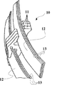
- FIG. 13 is a perspective view showing an endless metal belt 10 used for CVT.
- FIG. 14 is a partial perspective view showing a part of the endless metal belt 10 partially disassembled.
- the endless metal belt 10 is formed into a ring shape as a whole by connecting a plurality of metal elements 11 each having a plate shape in the thickness direction.
- laminated rings 12 and 12 are inserted from both sides of the metal element 11 in the width direction.
- the laminated ring 12 is obtained by stacking 6 to 12 endless metal rings 13 having slightly different circumferential lengths.
- the innermost endless metal ring 13 is a first ring
- the endless metal ring 13 stacked on the outer side of the first ring is a second ring.
- the numbers increase from the inside toward the outside. Name it.
- the circumferential length of the outer ring is slightly longer than the inner ring, and when the outer ring is stacked on the inner ring, the two are substantially in close contact with each other over the entire circumference.
- each endless metal ring 13 In manufacturing the laminated ring 12, the circumferential length of each endless metal ring 13 must be controlled very strictly so that the interlayer clearance between the inner ring and the outer ring falls within a specified tolerance. For example, if the interlayer clearance between the ring of the kth layer and the ring of the (k + 1) th layer is excessively larger than a specified value, it will cause rubbing and cutting. Also, since 6 to 12 layers of rings must be stacked in order, if the interlayer clearance between the k-th layer ring and the (k + 1) -th layer ring is larger than the specified value, The ring and the ring of the (k ⁇ 1) -th layer are not included, and as a result, it cannot be assembled as a laminated ring. Of course, if there is no interlayer clearance or the thickness of the kth layer ring is larger than the inner periphery of the (k + 1) th layer ring when considering the plate thickness, it is natural that the layers cannot be stacked.
- the circumference of the ring is adjusted so that each ring has a predetermined circumference. That is, the ring is stretched to a predetermined circumference by applying tension. At this time, there is a target value of a predetermined circumference for each of the first ring, the second ring, and so on.
- various ideas have been proposed so far for adjusting the circumference with extremely high accuracy.
- JP-A-2011-185300 Patent Document 2
- JP-A-2013-52432 Patent Document 3 filed by the present applicant disclose a considerably devised peripheral length adjusting device and peripheral length adjusting process. Yes.
- a laminated ring that is, each endless metal belt constituting the laminated ring is naturally required to have high strength. Therefore, after adjusting the circumference, heat treatment such as aging, oxidation, and nitriding is performed, and for example, improvement in hardness and wear resistance is achieved (Patent Documents 4 and 5).
- An object of the present invention is to further improve the manufacturing efficiency of the laminated ring.
- the laminated ring manufacturing method of the present invention is A method for producing a laminated ring in which a plurality of endless metal rings having slightly different circumferences are laminated, A welding process in which the ends of the steel plates are welded together to form a cylindrical pipe; A ring cutting step of cutting the pipe at predetermined widths in a direction perpendicular to the axis and cutting out a plurality of rings; A polishing step of polishing the ring; A circumferential length adjusting step for adjusting the plurality of rings so as to have a predetermined circumferential length; A nitriding step of nitriding a plurality of the rings; An assembly step of combining a plurality of the rings so as to be stacked to form a stacked ring, In the assembly process, The rings are assembled so that adjacent rings in the pipe state become adjacent layers in the laminated ring.
- polishing step It is preferable to polish one by one so that the order cut out in the ring cutting step can be traced.
- the nitriding step It is preferable to perform the nitriding treatment in a state where the rings that are adjacent to each other in the pipe state are set on a jig so as to be adjacent to each other.
- the circumference adjustment step It is preferable to adjust the circumference of each ring so that the rings that are adjacent to each other in the pipe state become adjacent layers in the laminated ring.
- the laminated ring manufacturing method of the present invention is A method for producing a laminated ring in which a plurality of endless metal rings having slightly different circumferences are laminated, A welding process in which the ends of the steel plates are welded together to form a cylindrical pipe; A ring cutting step of cutting the pipe at predetermined widths in a direction perpendicular to the axis and cutting out a plurality of rings; A polishing step of polishing the ring; A circumferential length adjusting step for adjusting the plurality of rings so as to have a predetermined circumferential length; A nitriding step of nitriding a plurality of the rings; An assembly step of combining a plurality of the rings so as to be stacked to form a stacked ring, In the assembling step, a predetermined number of the plurality of rings cut out from one pipe is used to assemble as one laminated ring.
- the laminated ring manufacturing method of the present invention is A method for producing a laminated ring in which a plurality of endless metal rings having slightly different circumferences are laminated, A welding process in which the ends of the steel plates are welded together to form a cylindrical pipe; A ring cutting step of cutting the pipe at predetermined widths in a direction perpendicular to the axis and cutting out a plurality of rings; A polishing step of polishing the ring; A circumferential length adjusting step for adjusting the plurality of rings so as to have a predetermined circumferential length; A nitriding step of nitriding a plurality of the rings; An assembly step of combining a plurality of the rings so as to be stacked to form a stacked ring, In the assembling step, a predetermined number of the plurality of rings cut out from a half length of the pipe is used to assemble as one laminated ring.
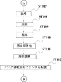
- stacking ring manufacturing method The flowchart of a lamination
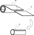
- the figure which shows a mode that the steel plate cut out from the roll is made into a pipe.
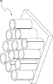
- the figure which shows a mode that 12 pipes are collectively solution-treated.
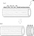
- the figure which shows a mode that 18 rings are cut out from one pipe.
- FIG. 1 The figure which shows a mode that the ring was set to the ring loading jig
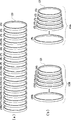
- stacking ring is made from the half of a pipe as the modification 1.
- FIG. 1 The figure which shows a mode that two laminated rings are made from one pipe as the modification 2.
- disassembles an endless metal belt and shows the part.
- FIG. 1 illustrates a state where the steel plate 21 cut out from the roll 20 is used as the pipe 22.
- the material of the roll 20 is steel such as maraging steel or stainless steel.
- each pipe 22 is cut in a direction orthogonal to the axis to cut out the ring 23 (ST105). Since this step is one of the essential points of the present invention, it will be described in detail.
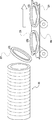
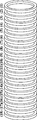
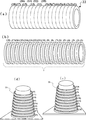
- FIGS. 6, 7, and 8 show how 18 rings 23 are cut out from one pipe 22. What is important here is that even if a plurality of (here, 18) rings 23 are cut out from one pipe 22, the order of the cut out rings 23 is kept the same as the original pipe state before cutting out. It is to be. (The most important thing is the mutual positional relationship of where the cut rings were in the pipe 22, but the positional relationship within the pipe is ordered from the right end of the pipe so that the explanation is easy to understand. Replace with and explain.)
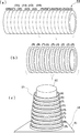
- FIG. 6A shows the pipe 22 before the ring 23 is cut out. It is assumed that the pipe 22 is ordered in the width unit of the ring 23 from the right end. Since 18 rings 23 are cut out from one pipe 22, the pipes 22 are numbered from 1 to 18 in units of a predetermined width from the right end. Then, as shown in FIG. 6B, the pipe 22 is cut from the right end. At this time, the order of the rings 23 is maintained even after being cut out. That is, management is performed so that the mutual relationship of the order of the rings 23 is not disturbed. For example, as shown in FIG. 7, if the pipes 22 are cut in the numerical order from the right end and the cut rings 23 are conveyed by the belt conveyor 90 in the cut out order, the order of the rings 23 is not lost. (See FIG. 8).
- the cut ring is polished (ST106). Removes burr and rounds (chamfers). Here too, it is important to polish so that the order of the rings 23 is not lost. For example, brush polishing may be performed one by one in order. Alternatively, burrs may be removed or rounded (chamfered) with a laser one by one. Further, barrel polishing may be performed one by one in order.
- each ring 23 is rolled to have a predetermined thickness. For example, the thickness direction of the ring 23 is sandwiched between a pair of rolling rollers and pressed.
- the second solution treatment (ST110), heating and cooling are performed to restore the deformation of the metal structure due to rolling (ST108).
- the circumference of the ring 23 is adjusted so that each rolled ring 23 has a predetermined circumference (ST111). That is, the ring 23 is extended by applying tension (tension), and adjustment is performed so that the ring 23 has a predetermined circumference. At this time, there is a target value of a predetermined circumference for each of the first ring, the second ring, and so on.
- a tension tensile force
- a device has been devised so as not to lower the durability of the ring 23 while adjusting the circumference with extremely high accuracy. (For example, JP 2011-185300 A and JP 2013-52432 A)
- FIG. 9 shows the rings that are the targets of circumference adjustment arranged side by side so as to maintain the original order.
- the ring order has been managed so as not to be disturbed, so it can be understood that the rings 23 are arranged so as to maintain the original order as shown in FIG. I will.
- 18 rings 23 are cut out from one pipe 22 to make two sets of laminated rings. Therefore, one of the two sets of laminated rings is a first laminated ring 12A, and the other is a second laminated ring 12B. Further, the innermost ring in the laminated ring is referred to as a first ring, and the ring laminated on the outer side of the first ring is referred to as a second ring. Hereinafter, the numbers are increased from the inner side toward the outer side.
- the first ring (1) is made to be the first ring of the first stacked ring 12A (see FIG. 9B).
- the second ring (2) is made to be the second ring of the first laminated ring 12A.
- the third ring (3) is made to be the third ring of the first laminated ring 12A.
- the ninth ring (9) is made to be the ninth ring of the first stacked ring 12A.
- the first ring (1) is adjusted to the circumference of the first ring
- the second ring (2) is adjusted to the circumference of the second ring.
- FIG. 9B is a diagram schematically showing a state after the circumference adjustment is performed on each ring 23 so as to obtain the target value of the circumference of each layer as described above.
- FIG. 10 is a diagram illustrating a state in which the ring 23 is set on the ring stacking jig 80.
- a set of rings to be assembled in the future as a laminated ring is set on the ring stacking jig.
- An example of the ring loading jig is shown in FIG.
- the ring stacking jig 80 includes a bottom plate 81 and a column 82 standing on the bottom plate 81, and the column 82 is provided with a plurality of flanges (not shown).
- the ring 23 is hooked on the collar portion, so that one set (that is, nine) of the rings 23 can be set on one ring stacking jig 80.
- the ring 23 is set on the ring stacking jig 80 so that the adjacent layers are adjacent to each other. It is preferable.
- the first ring that is, the first ring
- the second ring that is, the second ring
- the third ring that is, the second ring
- the third ring is set. (Hereafter, the same is omitted.)
- a ring stacking jig 80 on which the ring 23 is set is placed on a transfer table (not shown) (ST114) and sent to a heat treatment furnace.
- the heat treatment itself is a well-known process, and the ring 23 is subjected to aging (ST115), oxidation (ST116), and nitridation (ST117).
- aging treatment ST115
- oxidation ST116
- nitridation ST117
- aging treatment heating is performed up to a predetermined temperature, and after holding for a sufficient time, cooling is performed.
- an oxidation treatment is performed at a predetermined oxidation treatment temperature in an oxidation atmosphere to generate an oxide layer.
- nitriding is performed at a predetermined nitriding temperature in a nitriding atmosphere to generate a nitride layer.
- the heat treatment furnace has a plurality of processing chambers partitioned by doors, and the ring stacking jig 80 is configured to turn around the processing chambers in turn by a transfer table.
- the transfer table is carried out of the heat treatment furnace (ST118).
- the ring 23 subjected to the heat treatment is assembled as a laminated ring 12 through a predetermined inspection (for example, surface inspection ST119).
- a predetermined inspection for example, surface inspection ST119.
- nine rings 23 set in one ring stacking jig 80 as it is. May be assembled as a laminated ring 12.
- the laminated ring 12 manufactured in this way may be shipped.
- the adjacent rings in the case of the pipe 22 may be adjacent layers in the laminated ring 12.
- the roll 20 that is a material has variations in plate thickness and material composition depending on the location.
- plate thickness there is a variation of about plus or minus 3 ⁇ m to 4 ⁇ m depending on the location.
- the end portions are welded to form the pipe 22, but depending on the location, welding is performed. It is unavoidable that the quality varies.
- the rings adjacent to each other at the time of the pipe 22 are made to be adjacent layers in the laminated ring 12 as well.
- the rings adjacent to each other at the time of the pipe 22 it can be expected that the composition, the plate thickness, and the welding quality are substantially the same.
- the layers adjacent to each other in the laminated ring 12 are subjected to heat treatment under substantially the same conditions.
- the nine-layer ring 23 can be assembled as the laminated ring 12 with the package as set in the ring loading jig 80. This leads to deletion of operations for measuring, sorting, and selecting the ring 23 after the heat treatment. As a result, labor and cost are reduced, and manufacturing efficiency is improved.
- Modification 1 of the present invention will be described.
- “to make the rings adjacent to each other in the case of pipes be adjacent to each other in the laminated ring” means that variation after heat treatment between adjacent layers is minimized. This is considered the best mode.
- the cut-out rings 23 must be sequentially processed one by one, there is a problem that the load is large in the management of the manufacturing process.
- the laminated ring 12 can be finally assembled, and the standard (standard such as interlayer clearance) as the laminated ring 12 should be satisfied. It is permissible to change the order.
- the order may be changed in one set (for example, 9 rings) constituting one laminated ring.
- two laminated rings are made from one pipe 22.
- the first laminated ring is taken from the right half of the pipe 22, and the second laminated ring is taken from the left half of the pipe.
- the second laminated ring is omitted for the sake of paper width.
- the ninth ring is cut out from the first ring constituting the first laminated ring from the right half of the pipe 22.
- the order of the nine rings cut out from the right half of the pipe 22 need not be managed. That is, after nine rings 23 are cut out from the right half of the pipe 22, these may be batch-processed. For example, nine rings 23 may be barrel-polished together. The order of the nine rings can no longer be understood, but if it is about one set (for example, nine) constituting one laminated ring, the composition, plate thickness, weld quality can be obtained even if the place of the pipe is separated. It can be expected that there is no such big difference. Any one of the nine rings is a first ring, one of the remaining rings is a second ring, and one of the remaining rings is a third ring (hereinafter abbreviated).
- the first ring (1) and the ninth ring (9) may be adjacent layers.
- FIG. 11C illustrates a case where the first ring (1) is the fourth ring and the ninth ring is the fifth ring.
- the correspondence of which ring is numbered is no longer known, and this is only virtually numbered appropriately.
- Even in such a case since there is no significant difference in composition, plate thickness, welding quality, etc., it can be expected that the variation in interlayer clearance will be extremely small even if the heat treatment is extended to some extent.
- the 10th to 18th rings may be shuffled when the first to ninth rings constituting the second laminated ring are made from the left half of the pipe 22. Since it is the same as the above, repeated description is omitted.
- Modification 2 Furthermore, the modification 2 is demonstrated.
- the order is allowed to change in one pipe. That is, 18 rings may be cut out from one pipe and these may be batch processed. For example, 18 rings 23 may be barrel-polished together. The order of the 18 rings can no longer be understood, but within the same pipe, it can be expected that there will be no significant difference in composition, plate thickness, weld quality, etc., even if the location of the pipe is far away.
- a first laminated ring is formed from half of the 18 rings, and a second laminated ring is formed from the remaining half.
- the first ring (1) and the 18th ring (18) may be adjacent layers. Even in such a case, since there is no significant difference in composition, plate thickness, welding quality, etc., it can be expected that the variation in interlayer clearance will be extremely small even if the heat treatment is extended to some extent.
- the present invention is not limited to the above-described embodiment, and can be changed as appropriate without departing from the spirit of the present invention.
- 1st Embodiment the case where a ring was processed one by one was illustrated in the subsequent process so that the order of the cut-out ring might not change. It is easy to understand that they are put on the flow work in the cut order so as not to change the order, but there is of course room for various ideas to improve the production efficiency.
- the order may be traced later. For example, you may mark so that the order may be understood with respect to each cut-out ring.
- the rings can be rearranged before the circumferential length adjusting process or the heat treatment.
- various actual manufacturing processes may be devised such as processing a plurality of rings in parallel in a plurality of lanes.
Landscapes
- Chemical & Material Sciences (AREA)
- Engineering & Computer Science (AREA)
- Mechanical Engineering (AREA)
- Organic Chemistry (AREA)
- Materials Engineering (AREA)
- Metallurgy (AREA)
- Chemical Kinetics & Catalysis (AREA)
- General Engineering & Computer Science (AREA)
- Physics & Mathematics (AREA)
- Thermal Sciences (AREA)
- Crystallography & Structural Chemistry (AREA)
- Heat Treatment Of Articles (AREA)
- Grinding And Polishing Of Tertiary Curved Surfaces And Surfaces With Complex Shapes (AREA)
- Solid-Phase Diffusion Into Metallic Material Surfaces (AREA)
Abstract
Priority Applications (3)
| Application Number | Priority Date | Filing Date | Title |
|---|---|---|---|
| EP14817076.4A EP3015564B1 (fr) | 2013-06-25 | 2014-05-14 | Procédé de fabrication de bagues stratifiées |
| CN201480036712.7A CN105358731B (zh) | 2013-06-25 | 2014-05-14 | 层叠环的制造方法 |
| US14/898,586 US10088013B2 (en) | 2013-06-25 | 2014-05-14 | Manufacturing method for multi-layered ring |
Applications Claiming Priority (2)
| Application Number | Priority Date | Filing Date | Title |
|---|---|---|---|
| JP2013132604A JP6036574B2 (ja) | 2013-06-25 | 2013-06-25 | 積層リングの製造方法 |
| JP2013-132604 | 2013-06-25 |
Publications (1)
| Publication Number | Publication Date |
|---|---|
| WO2014207984A1 true WO2014207984A1 (fr) | 2014-12-31 |
Family
ID=52141361
Family Applications (1)
| Application Number | Title | Priority Date | Filing Date |
|---|---|---|---|
| PCT/JP2014/002551 Ceased WO2014207984A1 (fr) | 2013-06-25 | 2014-05-14 | Procédé de fabrication de bagues stratifiées |
Country Status (5)
| Country | Link |
|---|---|
| US (1) | US10088013B2 (fr) |
| EP (1) | EP3015564B1 (fr) |
| JP (1) | JP6036574B2 (fr) |
| CN (1) | CN105358731B (fr) |
| WO (1) | WO2014207984A1 (fr) |
Families Citing this family (6)
| Publication number | Priority date | Publication date | Assignee | Title |
|---|---|---|---|---|
| CN106271423B (zh) * | 2016-08-26 | 2018-08-31 | 中航动力股份有限公司 | 一种合金类薄壁焊接垫圈的加工方法 |
| JP2018054081A (ja) * | 2016-09-30 | 2018-04-05 | アイシン・エィ・ダブリュ株式会社 | リングの製造方法 |
| WO2018062549A1 (fr) * | 2016-09-30 | 2018-04-05 | アイシン・エィ・ダブリュ株式会社 | Procédé de nettoyage d'une partie à souder, système de soudage et procédé de fabrication de bague |
| PL234237B1 (pl) * | 2017-10-19 | 2020-01-31 | Instytut Mech Precyzyjnej | Sposób jarzeniowego azotowania wewnętrznych powierzchni tulei, zwłaszcza luf |
| JP2019177403A (ja) * | 2018-03-30 | 2019-10-17 | トヨタ自動車株式会社 | 無端金属リングの製造方法 |
| CN111571129A (zh) * | 2020-05-11 | 2020-08-25 | 哈尔滨锅炉厂有限责任公司 | 承压设备大直径薄壁圆环的制造方法 |
Citations (7)
| Publication number | Priority date | Publication date | Assignee | Title |
|---|---|---|---|---|
| JP2003105443A (ja) * | 2001-09-27 | 2003-04-09 | Honda Motor Co Ltd | 金属製積層リングの製造方法 |
| JP2005155755A (ja) | 2003-11-25 | 2005-06-16 | Toyota Motor Corp | 無段変速機に用いられる無端金属リングの製造装置および製造方法 |
| JP2005337339A (ja) * | 2004-05-25 | 2005-12-08 | Honda Motor Co Ltd | 無端状金属ベルトの製造方法 |
| JP2009249646A (ja) | 2008-04-01 | 2009-10-29 | Toyota Motor Corp | フープの製造方法及び製造装置 |
| WO2011077579A1 (fr) | 2009-12-25 | 2011-06-30 | トヨタ自動車株式会社 | Procédé de production d'un anneau stratifié |
| JP2011185300A (ja) | 2010-03-04 | 2011-09-22 | Toyota Motor Corp | 積層リングの製造方法 |
| JP2013052432A (ja) | 2011-09-06 | 2013-03-21 | Toyota Motor Corp | 無端金属リングの製造装置及び製造方法 |
Family Cites Families (4)
| Publication number | Priority date | Publication date | Assignee | Title |
|---|---|---|---|---|
| US6631542B1 (en) * | 1999-05-28 | 2003-10-14 | Honda Giken Kogyo Kabushiki Kaisha | Method of manufacturing laminated ring and heat treatment apparatus for use in such method |
| JP3779129B2 (ja) * | 2000-05-18 | 2006-05-24 | 本田技研工業株式会社 | 熱処理方法 |
| JP3884246B2 (ja) | 2001-08-08 | 2007-02-21 | 本田技研工業株式会社 | Cvtベルト用フープの製造方法 |
| KR101080533B1 (ko) * | 2009-02-09 | 2011-11-04 | 김지현 | 잔여소재의 이용이 가능한 원형 절삭공구의 제조방법 |
-
2013
- 2013-06-25 JP JP2013132604A patent/JP6036574B2/ja not_active Expired - Fee Related
-
2014
- 2014-05-14 EP EP14817076.4A patent/EP3015564B1/fr not_active Not-in-force
- 2014-05-14 US US14/898,586 patent/US10088013B2/en not_active Expired - Fee Related
- 2014-05-14 WO PCT/JP2014/002551 patent/WO2014207984A1/fr not_active Ceased
- 2014-05-14 CN CN201480036712.7A patent/CN105358731B/zh not_active Expired - Fee Related
Patent Citations (7)
| Publication number | Priority date | Publication date | Assignee | Title |
|---|---|---|---|---|
| JP2003105443A (ja) * | 2001-09-27 | 2003-04-09 | Honda Motor Co Ltd | 金属製積層リングの製造方法 |
| JP2005155755A (ja) | 2003-11-25 | 2005-06-16 | Toyota Motor Corp | 無段変速機に用いられる無端金属リングの製造装置および製造方法 |
| JP2005337339A (ja) * | 2004-05-25 | 2005-12-08 | Honda Motor Co Ltd | 無端状金属ベルトの製造方法 |
| JP2009249646A (ja) | 2008-04-01 | 2009-10-29 | Toyota Motor Corp | フープの製造方法及び製造装置 |
| WO2011077579A1 (fr) | 2009-12-25 | 2011-06-30 | トヨタ自動車株式会社 | Procédé de production d'un anneau stratifié |
| JP2011185300A (ja) | 2010-03-04 | 2011-09-22 | Toyota Motor Corp | 積層リングの製造方法 |
| JP2013052432A (ja) | 2011-09-06 | 2013-03-21 | Toyota Motor Corp | 無端金属リングの製造装置及び製造方法 |
Also Published As
| Publication number | Publication date |
|---|---|
| JP6036574B2 (ja) | 2016-11-30 |
| EP3015564A4 (fr) | 2016-06-22 |
| CN105358731A (zh) | 2016-02-24 |
| EP3015564B1 (fr) | 2018-06-20 |
| CN105358731B (zh) | 2017-05-17 |
| US10088013B2 (en) | 2018-10-02 |
| JP2015007270A (ja) | 2015-01-15 |
| EP3015564A1 (fr) | 2016-05-04 |
| US20160138674A1 (en) | 2016-05-19 |
Similar Documents
| Publication | Publication Date | Title |
|---|---|---|
| JP6036574B2 (ja) | 積層リングの製造方法 | |
| JP5999187B2 (ja) | 無端金属ベルトの製造方法及び無端金属ベルト並びにベルト式無段変速機 | |
| WO2018062532A1 (fr) | Procédé de fabrication d'anneaux | |
| EP1815160A1 (fr) | Courroie de poussee et son procede de fabrication | |
| JPH11173385A (ja) | ベルト式無段変速機用金属帯の製造方法 | |
| JP5712743B2 (ja) | 薄板状無端金属リングの製造装置及び製造方法 | |
| JP5621685B2 (ja) | 薄板状無端金属リングの製造方法 | |
| JP2011185300A (ja) | 積層リングの製造方法 | |
| JP5776455B2 (ja) | 無端金属リングの製造装置及び製造方法 | |
| JP5392053B2 (ja) | 積層リングの製造方法 | |
| JP4923287B2 (ja) | 金属リング周長補正装置 | |
| WO2018221646A1 (fr) | Procédé de production d'anneau sans fin | |
| JP5949478B2 (ja) | 積層リング及び積層リング製造方法 | |
| US2337157A (en) | Crankshaft construction | |
| JP2014184478A (ja) | 無端金属ベルトの製造方法 | |
| CN102812263B (zh) | 同时制造多于一个用于圆锥滚子轴承的轴承圈的方法 | |
| US20190168351A1 (en) | Method for manufacturing ring and ring polishing apparatus | |
| WO2018221645A1 (fr) | Procédé de fabrication d'anneau sans fin et anneau sans fin | |
| JP2006200019A (ja) | スラスト軸受の軌道盤の製造方法およびスラスト軸受の製造方法 | |
| US1016098A (en) | Method of making toothed-wire covered cylinders. | |
| JP4546844B2 (ja) | スラスト軸受の軌道盤の製造方法およびスラスト軸受の製造方法 | |
| JP2005337339A (ja) | 無端状金属ベルトの製造方法 | |
| JP2013121609A (ja) | 無端金属リングの製造装置及び製造方法 | |
| JP2019120276A (ja) | Cvtリング素材の製造方法 | |
| JP2006334633A (ja) | 丸形鋼管の製造方法及び丸形鋼管の製造設備 |
Legal Events
| Date | Code | Title | Description |
|---|---|---|---|
| WWE | Wipo information: entry into national phase |
Ref document number: 201480036712.7 Country of ref document: CN |
|
| 121 | Ep: the epo has been informed by wipo that ep was designated in this application |
Ref document number: 14817076 Country of ref document: EP Kind code of ref document: A1 |
|
| WWE | Wipo information: entry into national phase |
Ref document number: 2014817076 Country of ref document: EP |
|
| WWE | Wipo information: entry into national phase |
Ref document number: 14898586 Country of ref document: US |
|
| NENP | Non-entry into the national phase |
Ref country code: DE |
|
| WWE | Wipo information: entry into national phase |
Ref document number: IDP00201600441 Country of ref document: ID |