WO2014208210A1 - Feuille creuse - Google Patents
Feuille creuse Download PDFInfo
- Publication number
- WO2014208210A1 WO2014208210A1 PCT/JP2014/062625 JP2014062625W WO2014208210A1 WO 2014208210 A1 WO2014208210 A1 WO 2014208210A1 JP 2014062625 W JP2014062625 W JP 2014062625W WO 2014208210 A1 WO2014208210 A1 WO 2014208210A1
- Authority
- WO
- WIPO (PCT)
- Prior art keywords
- hollow plate
- surface layer
- pair
- sealing
- layer portions
- Prior art date
- Legal status (The legal status is an assumption and is not a legal conclusion. Google has not performed a legal analysis and makes no representation as to the accuracy of the status listed.)
- Ceased
Links
Images



Classifications
-
- B—PERFORMING OPERATIONS; TRANSPORTING
- B32—LAYERED PRODUCTS
- B32B—LAYERED PRODUCTS, i.e. PRODUCTS BUILT-UP OF STRATA OF FLAT OR NON-FLAT, e.g. CELLULAR OR HONEYCOMB, FORM
- B32B3/00—Layered products comprising a layer with external or internal discontinuities or unevennesses, or a layer of non-planar shape; Layered products comprising a layer having particular features of form
- B32B3/26—Layered products comprising a layer with external or internal discontinuities or unevennesses, or a layer of non-planar shape; Layered products comprising a layer having particular features of form characterised by a particular shape of the outline of the cross-section of a continuous layer; characterised by a layer with cavities or internal voids ; characterised by an apertured layer
Definitions
- the present invention relates to a hollow plate, and more particularly, to a hollow plate whose end is sealed.
- a plate having a hollow structure is widely used, for example, for building members such as cases, trays, interior walls, and the like because of its excellent weight reduction, rigidity, heat insulation, and economic efficiency.
- a plate having a hollow structure has an open end face, and foreign matters such as liquids and dust are liable to enter from the end face, and there are problems in water tightness, air tightness, and dustproofness. Furthermore, since the end face is open, it has a poor aesthetic appearance and is associated with a decrease in texture. Therefore, a plate having a hollow structure requires a process for sealing the opening of the end face in order to improve watertightness, airtightness, dustproofness, aesthetics and texture.
- the end portions of the upper and lower surface layer portions are folded while only one rib near the end portion is folded among the ribs arranged between the upper and lower surface layer portions.
- the edge processing is performed so that the shape of is rounded. Since the shape of the end is rounded, it is difficult to make a hole in the end.
- the end portion is rounded, so that the plate having the hollow structure cannot be firmly fixed to the other member. There's a problem.
- the present invention has been made to solve the above-described problems, and provides a hollow plate that improves water tightness, air tightness, aesthetics and texture, and can be securely fixed to other members. Objective.
- the hollow plate according to the present invention that achieves the above object has a pair of surface layer portions having a plate shape and a support portion that has a hollow structure and supports the pair of surface layer portions apart from each other.
- the hollow plate further includes a sealing portion that seals between the outer peripheral edges so that the outer peripheral edges of the pair of surface layer portions are parallel to each other.
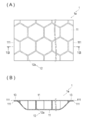
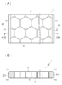
- FIG. 1A is a schematic diagram illustrating an example of a configuration of a hollow plate according to an embodiment
- FIG. 1A is a plan view of the hollow plate
- FIG. 1B is a cross section taken along line 1B-1B in FIG.
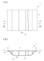
- FIG. 2A is a schematic diagram illustrating another example of the configuration of the hollow plate according to the embodiment
- FIG. 2A is a plan view of the hollow plate
- FIG. 2B is a line 2B-2B in FIG. 2A.
- FIG. 3A is a schematic view showing still another example of the configuration of the hollow plate according to the embodiment
- FIG. 3A is a plan view of the hollow plate
- FIG. 3B is a line 3B-3B in FIG.
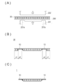
- FIG. 5A is a schematic diagram illustrating an example of a molding process subsequent to FIG. 4,
- FIG. 5A is a diagram illustrating a state in which a base material of a hollow plate is carried into a molding apparatus, and
- FIG. 5C is a view showing a hollow plate formed by cutting an extra portion on the outer periphery from the sealing portion.
- FIG. 6A is a schematic diagram showing an example of the thickness and width of a sealing portion of a hollow plate, and FIG.
- FIG. 6A is a diagram showing a hollow plate in which a sealing portion is formed by compressing a pair of surface layer portions
- FIG. B) is a view showing a hollow plate in which a pair of surface layer portions and a support portion are compressed to form a sealing portion.
- FIG. 7A is a schematic diagram illustrating another example of the molding process subsequent to FIG. 4.
- FIG. 7A is a diagram illustrating a state in which the base material is carried into the molding apparatus, and FIG. The figure which shows the state in process of shaping
- FIG.7 (C) is a figure which shows the hollow plate formed by cut
- FIGS. 8A and 8B are schematic views illustrating an enlarged sealing portion of a hollow plate, FIG.
- FIG. 8A is a diagram illustrating an example of a sealing portion
- FIG. 8B is a diagram illustrating another example of a sealing portion
- FIG. 8C is a diagram illustrating still another example of the sealing portion.
- FIG. 9 (A) is a schematic diagram which shows an example at the time of applying a hollow plate to the interior member of a vehicle
- FIG. 9 (B) is 9B of FIG. 9 (A).
- FIG. 9C is a cross-sectional view showing the configuration in the region
- FIG. 9C is a cross-sectional view showing the proportionality.
- FIG. 10A is a schematic view showing a state in which the dimension for separating the pair of surface layer portions by the support portion decreases toward the sealing portion
- FIG. 10A is a diagram showing an example in which the inclination is relatively gentle
- FIG. ) Is a diagram showing an example in which the slope is relatively steep.
- FIG. 11A is a perspective view showing a luggage board according to an embodiment of a hollow plate
- FIG. 11A is a perspective view showing the luggage board
- FIG. 11B is a view taken along a line 11B-11B in FIG.
- FIG. 11C is a cross-sectional view taken along line 11C-11C of FIG. 11A
- FIG. 11D is a view showing a luggage board to which a decorative material is sewn.
- FIG. 12 is a top view of a hollow plate
- FIG.12 (B) is FIG.
- FIG. 12 is a sectional view taken along line 12B-12B.
- the hollow plate 1 according to the embodiment will be described with reference to FIGS.
- FIG. 1 is a schematic view showing an example of the configuration of the hollow plate 1.
- FIG. 1 (A) is a plan view of the hollow plate 1
- FIG. 1 (B) is a line 1B-1B in FIG. 1 (A).
- 2 is a schematic view showing another example of the configuration of the hollow plate 1.
- FIG. 2 (A) is a plan view of the hollow plate 1
- FIG. 2 (B) is 2B-2B in FIG. 2 (A).
- FIG. 3 is a schematic view showing still another example of the configuration of the hollow plate 1.
- FIG. 3 (A) is a plan view of the hollow plate 1
- FIG. 3 (B) is a view of 3B- of FIG. 3 (A). It is sectional drawing which follows a 3B line.
- the hollow plate 1 has a pair of surface layer portions 11 having a plate shape and a support portion 12 having a hollow structure and supporting the pair of surface layer portions 11 apart from each other.
- the hollow plate 1 further includes a sealing portion 13 that seals between the outer peripheral edges 111 such that the outer peripheral edges 111 of the pair of surface layer portions 11 are parallel to each other. Details will be described below.
- the hollow plate 1 is a honeycomb hollow plate 1a in which the support portion 12 is a support portion 12a having a hexagonal columnar honeycomb structure as shown in FIGS. 1 (A) and 1 (B).
- the base material of the honeycomb hollow plate 1a is produced by various molding methods such as an extrusion molding method and an injection molding method.
- Examples of commercially available products include, for example, Texel (registered trademark) manufactured by Gifu Plastic Industry Co., Ltd. This product (Texel (registered trademark)) forms a surface layer portion and a support portion by folding a single plate in which a portion to be a surface layer portion and a portion to be a support portion are integrally formed.
- the hollow plate 1 is a corrugated cardboard hollow plate 1b in which the support portion 12 is a linear or corrugated support portion 12b as shown in FIGS. 2 (A) and 2 (B), for example.
- the base material of the cardboard hollow plate 1b is produced by various molding methods such as an extrusion molding method and an injection molding method.
- the dump plate brand name by Ube Eximo Co., Ltd. is mentioned, for example.
- the hollow plate 1 is an air cap hollow plate 1c in which the support portion 12 is a cylindrical support portion 12c as shown in FIGS. 3 (A) and 3 (B), for example.
- the base material of the air cap hollow plate 1c is produced by various molding methods such as an extrusion molding method and an injection molding method.
- the plastic pearl (trademark) by Kawakami Sangyo Co., Ltd. is mentioned, for example.
- the pair of surface layer portions 11 and the support portion 12 are both made of the same material.
- the hollow plate 1 is higher in rigidity than a plate filled with the same material and having the same weight (not having a hollow structure).
- the base material of the hollow plate 1 is not limited to the above example and can be variously modified.
- the base material may have a configuration in which a support portion 12 obtained by press-molding a single plate into an uneven shape is disposed between a pair of surface layer portions 11.
- the base material has a shape in which the support portion 12 has a top surface, a bottom surface, and a box having side surfaces arranged adjacent to each other, and a surface layer portion is provided on each of the top surface and the bottom surface of the support portion 12, and the top surface and the bottom surface of the support portion.
- the structure which provides a surface layer part only in any one surface of this, or the structure in which each of the upper surface and lower surface of a box forms a surface layer part may be sufficient.
- the hollow plate 1 (1a, 1b, 1c) in which the surface layer portion 11 and the support portion 12 are formed from the same material has been illustrated, the surface layer portion 11 and the support portion 12 can also be formed from different materials.
- the material of the surface layer portion 11 is not particularly limited, and examples thereof include a resin material, a metal material, and wood.
- resin material include ABS resin, AES resin, styrene resin, acrylic resin, halogen-containing resin, olefin resin (polyethylene resin, polypropylene resin, cyclic olefin resin, TPO, etc.), polycarbonate resin, polyester resin (saturated).
- resin materials can be used alone or in combination of two or more.
- an elastomer component such as ethylene propylene rubber or silicone rubber, or an inorganic filler such as talc or glass fiber for improving the strength may be arbitrarily mixed in the resin.
- resin materials are preferable from the viewpoint of weight reduction and economy, and olefin resins, ABS resins, polycarbonate resins, and polyamide resins are more preferable.
- the metal material include iron, stainless steel, aluminum, titanium, magnesium, and the like. These metal materials can be used alone or in combination of two or more. Of these metals, aluminum is more preferable from the viewpoint of weight reduction, which is one of the features of the hollow plate 1.
- the pair of surface layer portions 11 may be formed from the same material or different materials.
- the material of one surface layer portion can be selected from the viewpoint of design, and the material of the other surface layer portion can be selected from the viewpoint of strength.
- the material of the support portion 12 is not particularly limited, and examples thereof include a resin material and a metal material, and can be selected from the materials listed for the surface layer portion 11.
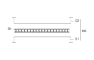
- FIG. 4 is a schematic diagram showing an example of the forming process of the hollow plate 1, and shows a state where the base material 30 of the hollow plate 1 is carried into the heating device 100.
- FIG. 5 is a schematic diagram illustrating an example of the molding process subsequent to FIG. 4, and FIG. 5A is a diagram illustrating a state in which the base material 30 of the hollow plate 1 is carried into the molding apparatus 200, and FIG. These are figures which show the base material 30 in which the sealing part 13 was shape
- FIG. 5 is a schematic diagram showing an example of the forming process of the hollow plate 1, and shows a state where the base material 30 of the hollow plate 1 is carried into the heating device 100.
- FIG. 5 is a schematic diagram illustrating an example of the molding process subsequent to FIG. 4
- FIG. 5A is a diagram illustrating a state in which the base material 30 of the hollow plate
- the hollow plate 1 according to the embodiment has a flat plate shape.
- the plate-shaped base material 30 needs to be heated and softened before press molding.
- the heating device 100 is used to heat and soften the base material 30. As shown in FIG. 4, the heating device 100 includes a lower heating member 101 and an upper heating member 102.
- the lower heating member 101 and the upper heating member 102 are configured to be capable of heating the base material 30 rapidly and evenly, such as a thermal oven or a heater.
- the heating temperature is a temperature near the softening point of the base material 30 (including the pair of surface layer portions 11 and the support portion 12), and varies depending on the material of the base material 30.
- the molding apparatus 200 is used for press-molding a flat plate-shaped base material 30.
- the molding device 200 presses the inner side of the outer peripheral edges of the pair of surface layer portions 11 of the base material 30 softened by heating by the heating device 100 to press-mold the sealing portion 13.
- the molding apparatus 200 has a lower mold 201 and an upper mold 202 that are relatively movably movable.
- the molding apparatus 200 has a convex part 201 a provided on the lower mold 201 so as to protrude toward the upper mold 202. As shown in FIGS. 5A and 5B, the convex portion 201 a presses the inside of the outer peripheral edges of the pair of surface layer portions 11 of the base material 30 together with the upper mold 202 to form the sealing portion 13. .
- the base material 30 in which the sealing portion 13 is molded is in the region (sealing region a1) where the sealing portion 13 of the base material 30 is formed. And is formed into the hollow plate 1 by removing a region (cut region c1) on the outer periphery than the sealing region a1 of the base material 30. As shown in FIG. 5C, the outer periphery of the hollow plate 1 is sealed with a sealing portion 13.
- the illustrated cutting member that cuts the base material 30 is, for example, a laser cutter, an NC (Numerical Control machining) laser cutter, or the like.
- the base material 30 is heated by the heating device 100 and the softened base material 30 is press-molded by the molding device 200.
- the present invention is not limited to this. You may press-mold while heating 30.
- a heating member such as a heater is provided in the lower mold 201 and the upper mold 202.
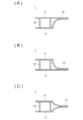
- FIG. 6 is a schematic diagram showing an example of the thickness T and the width W of the sealing portion 13 of the hollow plate 1.
- FIG. 6A shows the sealing portion 13 formed by compressing the pair of surface layer portions 11.
- FIG. 6B is a view showing the hollow plate 1 in which the sealing portion 13 is formed by compressing the pair of surface layer portions 11 and the support portion 12.
- the sealing part 13 compresses the outer peripheral edge 111 of the pair of surface layer parts 11 or compresses the outer peripheral edge 111 of the pair of surface layer parts 11 and the support part 12 that supports the outer peripheral edge 111. It is formed by.
- the rigidity increases as the material thickness of the surface layer portion 11 and the material thickness of the support portion 12 constituting the hollow plate 1 increase.
- the hollow plate 1 is less rigid as the material thickness of the surface layer portion 11 and the material thickness of the support portion 12 are reduced, but the volume and weight are reduced.
- the material and material thickness of the surface layer portion 11 and the material and material thickness of the support portion 12 are selected depending on the intended application.
- the thickness T of the sealing portion 13 is equal to or less than the total thickness of the pair of surface layer portions 11.
- the thickness of the sealing portion 13 is about 0.3 mm. It is possible to compress to a thickness of about 0.5 mm.
- the width W of the sealing portion 13 can be arbitrarily set.
- the hollow plate 1 has a lower rigidity as the width W of the sealing portion 13 increases.
- the width W of the sealing portion 13 is selected according to the required level of rigidity and product shape (design).
- the support portion 12 when the support portion 12 is disposed only in the center portion of the pair of surface layer portions 11 of the hollow plate 1 and the support portion 12 is not disposed in the vicinity of the outer peripheral edge 111, sealing is performed.
- the part 13 is formed by compressing the pair of surface layer parts 11.
- the thickness T of the sealing portion 13 is set to be equal to or less than the total thickness of the pair of surface layer portions 11.
- the thickness T of the sealing portion 13 is equal to or less than the total thickness of the pair of surface layer portions 11, but is not limited thereto, and is larger than the total thickness of the pair of surface layer portions 11. May be.
- the thickness T of the sealing portion 13 is equal to or less than the total thickness of the pair of surface layer portions 11, but is not limited thereto, and is larger than the total thickness of the pair of surface layer portions 11. May be.
- the molding device 300 compresses the outer peripheral edge 111 of the pair of surface layer parts 11 and the support part 12 that supports the vicinity of the outer peripheral edge 111 to form the sealing part 13 will be described.
- the sealing portion 13 is located outside the pair of surface layer portions 11.
- the support portion 12 that supports the periphery 111 and the vicinity of the outer periphery 111 is compressed and molded.
- the thickness T of the sealing portion 13 is formed to be equal to or less than the total thickness of the pair of surface layer portions 11.
- the thickness T of the sealing portion 13 is formed to be equal to or less than the total thickness of the pair of surface layer portions 11. Therefore, the watertightness and airtightness of the hollow plate 1 can be further improved.
- FIG. 7 is a schematic diagram illustrating another example of the molding process subsequent to FIG. 4.
- FIG. 7A is a diagram illustrating a state in which the base material 30 is carried into the molding apparatus 300
- FIG. 7C is a diagram showing a state in which the preform 30 is being molded by the molding apparatus 300
- FIG. 7C is a diagram showing the hollow plate 1 formed by cutting an extra portion on the outer periphery from the sealing portion 13.
- the hollow plate 1 according to the embodiment has a three-dimensional shape with a product form.
- the plate-shaped base material 30 needs to be softened through a heating process by the heating device 100 shown in FIG.
- the forming apparatus 300 is used for press-forming the base material 30 to form the three-dimensional hollow plate 1.
- the molding apparatus 300 includes a lower mold 301 and an upper mold 302 that are relatively close to and away from each other.
- the molding apparatus 300 is a vacuum molding apparatus, and has innumerable suction holes 301c and 302c for vacuum suction to the lower mold 301 and the upper mold 302.
- the plurality of suction holes 301c and 302c communicate with a vacuum pump (not shown) via a vacuum drawing pipe (not shown). Thereby, vacuum suction can be performed from the countless suction holes 301c and 302c.
- the hollow plate 1 having a three-dimensional shape may be formed by a general molding method similar to the molding by the molding apparatus 200 that is not vacuum molding.
- examples of the general molding method include single-sided vacuum molding and molding by thermal bending.
- the molding apparatus 300 vacuum-sucks the flat plate-shaped base material 30 that has been softened by the heating by the heating apparatus 100 from the numerous suction holes 301 c and 302 c of the lower mold 301 and the upper mold 302, and thereby lower mold 301 and upper mold 302. So that the position is not displaced.
- the lower mold 301 and the upper mold 302 compress the outer peripheral edge 111 of the pair of surface layer portions 11 of the softened base material 30 and the support portion 12 that supports the vicinity of the outer peripheral edge 111.
- molding apparatus 300 shape
- the forming apparatus 300 including the vacuum forming apparatus is described as a configuration that does not include a heating member that heats the base material 30, but is not limited thereto, and is applicable to a configuration including a heating member. .
- the forming apparatus 300 includes a convex portion 301a provided on the lower die 301 so as to protrude toward the upper die 302, and a pressing surface 301b provided so as to be surrounded by the convex portion 301a.
- the molding apparatus 300 includes a convex portion 302a provided on the upper die 302 so as to protrude toward the lower die 301, and a pressing surface 302b provided so as to surround the convex portion 302a.
- the pressing surface 301 b of the lower mold 301 presses the central portion of the surface layer portion 11 of the base material 30 together with the convex portion 302 a of the upper mold 302 to give the base material 30 a three-dimensional shape.
- the convex part 301 a of the lower mold 301 presses the outer peripheral edge 111 of the pair of surface layer parts 11 of the base material 30 together with the pressing surface 302 b of the upper mold 302 to form the sealing part 13. Thereby, the base material 30 which is a three-dimensional shape and whose outer peripheral edges of the pair of surface layer portions 11 are sealed is formed.
- the three-dimensional base material 30 in which the outer peripheral edges of the pair of surface layer portions 11 are sealed has the sealing portion 13 of the base material 30 formed therein.
- the hollow plate 1 is formed by cutting within the region (sealing region a2) and removing the region (cutting region c2) on the outer periphery of the base material 30 from the sealing region a2.
- the outer peripheral edge 111 of the hollow plate 1 is sealed with a sealing portion 13.
- the hollow plate 1 having a three-dimensional shape is improved in torsional rigidity as a plate material by being provided with the three-dimensional shape.
- FIG. 8 is an enlarged schematic diagram illustrating the sealing portion 13 of the hollow plate 1
- FIG. 8A is a diagram illustrating an example of the sealing portion 13
- FIG. 8B is a sealing portion
- FIG. 8C is a diagram showing still another example of the sealing portion 13.
- the sealing part 13 of the hollow plate 1 can have any sealing position as long as the gap between the outer peripheral edges 111 of the pair of surface layer parts 11 is sealed so that the outer peripheral edges 111 of the pair of surface layer parts 11 are parallel to each other. Can be set.
- the sealing position of the sealing part 13 is selected according to the product shape.
- the sealing position of the sealing portion 13 of the hollow plate 1 may be set in accordance with the position of the upper surface layer portion 11.
- the sealing position of the sealing portion 13 of the hollow plate 1 may be set in accordance with the position of the lower surface layer portion 11.
- the sealing position of the sealing portion 13 of the hollow plate 1 may be set in accordance with the position between the upper surface layer portion 11 and the lower surface layer portion 11.
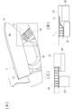
- FIG. 9 is a diagram showing an example when the hollow plate 1 formed with the sealing portion 13 is used as a product.
- FIG. 9A shows an example when the hollow plate 1 is applied to an interior member of a vehicle.
- FIG. 9B is a schematic diagram showing a configuration in the region 9B of FIG. 9A, and
- FIG. 9C is a schematic diagram showing a comparative example of FIG. 9B.
- FIG. 9A shows an example when the hollow plate 1 is applied to an interior member of a vehicle.
- FIG. 9B is a schematic diagram showing a configuration in the region 9B of FIG. 9A
- FIG. 9C is a schematic diagram showing a comparative example of FIG. 9B.
- the hollow plate 1 is used as an interior member or exterior member of a vehicle, and is attached to another member at a sealing portion 13.
- the hollow plate 1 is installed in a trunk room of a vehicle and used for a luggage board.
- the luggage board is installed on the raising material 50.
- the raising material 50 is installed on the emergency tire.
- the sealing position of the sealing portion 13 is the position of the upper surface layer portion 11 (see FIG. 8A), or the position between the upper surface layer portion 11 and the lower surface layer portion 11 (FIG. 8 ( C)).
- FIG. 9B an example in which the sealing position of the sealing portion 13 is matched with the upper surface layer portion 11 is given as an example.
- the luggage board is installed on the left and right body panels 60 sandwiching emergency tires by placing them on a bridge via an interior trim 70.
- FIG. 9C shows a conventional hollow plate 80 having a hollow structure, a raising member 50 ′, a body panel 60 ′, and a trim 70 ′ as a comparative example.
- the conventional luggage board (hollow plate 80) having a hollow structure has a height in the cross section, and in order to adjust the height with the trim 70 ', the height of the trim 70' must be increased. It was.
- the sealing part 13 is thin, the height of the trim 70 can be reduced. By doing in this way, the capacity
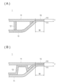
- FIG. 10 is a schematic view showing a state in which the dimension for separating the pair of surface layer portions 11 by the support portion 12 becomes smaller toward the sealing portion 13.
- FIG. 10A shows an example in which the inclination is relatively gentle.
- FIG. 10B is a diagram showing an example in which the slope is relatively steep.
- the dimension for separating the pair of surface layer portions 11 by the support portion 12 can be reduced toward the sealing portion 13.
- a position where the dimension for separating the pair of surface layer portions 11 by the support portion 12 starts to decrease (inclination start position of the hollow plate 1) is P1
- a position reaching the sealing portion 13 is P2.
- the maximum value of the length L from the inclination start position P1 to the inclination end position P2 in the surface direction of the hollow plate 1 is the height h of the support portion 12. The value is 20 times.
- the load when the weight is applied to the hollow plate 1 can be dispersed.
- the inclination from P1 to P2 is increased.
- a relatively steep configuration may be used.
- the sealing portion 13 of the hollow plate 1 is continuously sealed so as to surround the entire circumference of the hollow plate 1.
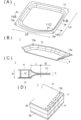
- FIG. 11 is a view showing a vehicle luggage board according to an embodiment of the hollow plate 1
- FIG. 11 (A) is a perspective view showing the luggage board
- FIG. 11 (B) is a view of FIG. 11 (A).
- 11B is a perspective view showing a cross section taken along the line 11B-11B
- FIG. 11C is a cross sectional view taken along the line 11C-11C in FIG. 11A
- FIG. 11D is a luggage board on which the decorative material 40 is sewn.
- FIG. 11 is a view showing a vehicle luggage board according to an embodiment of the hollow plate 1
- FIG. 11 (A) is a perspective view showing the luggage board
- FIG. 11 (B) is a view of FIG. 11 (A).
- 11B is a perspective view showing a cross section taken along the line 11B-11B
- FIG. 11C is a cross sectional view taken along the line 11C-11C in FIG. 11A
- FIG. 11D is a luggage board on which the decorative material 40 is
- the sealing part 13 has a hole part 13a connected to another member or a hole part 13b sewn with another member.
- the sealing portion 13 of the hollow plate 1 has a hole portion 13a.
- the sealing portion 13 of the hollow plate 1 of the present embodiment is formed by compressing the pair of surface layer portions 11 and the support portion 12 or compressing only the pair of surface layer portions 11. For this reason, as shown in FIG. 11C, the sealing portion 13 has a solid structure filled with the contents, so that the mechanical characteristics do not deteriorate even if the hole portion 13a is opened. Can be used.
- the hole 13a used for connection with other members in the hollow plate 1 a case where the hollow plate 1 is used for a luggage board of a vehicle will be described as an example.
- the luggage board can be securely fastened to the vehicle body panel by inserting a resin clip or a bolt through the hole 13a.
- quietness is increased by suppressing flapping of the luggage board during traveling.
- the hole 13b used for sewing with other members in the hollow plate 1 As an example of forming the hole 13b used for sewing with other members in the hollow plate 1, a case where the decorative material 40 is attached to the surface of the luggage board will be described as an example.
- the hole 13b used for sewing with the surface layer material is opened by stitching the sealing portion 13 with a sewing machine. Since the sealing part 13 is thin, it can be stitched easily.
- the decorative material 40 when the decorative material 40 is attached to the surface of the hollow plate 1, it can be performed by sewing in addition to gluing or heat welding.
- the designability by the stitch of the seam which penetrates the hole part 13b can be improved.
- Examples of the decorative material 40 include a laminate formed of a nonwoven fabric, a woven fabric, paper, a film, a highly foamed resin, or the like.
- Examples of the means for forming the laminate include an adhesion method using an adhesive and a heat fusion method. As a means for heat fusion, heat fusion may be performed by heat when the hollow plate 1 is press-molded (including heat at the time of forming the sealing portion 13).
- the hollow plate 1 of the present invention combines light weight, rigidity, water tightness, air tightness, dustproofness and appearance (high aesthetics and texture), it can be used for interior and exterior members of vehicles.
- vehicle interior components include instrument panels, cluster lids, glove box lids, knee bolsters, center consoles, headlinings, assist grips, door trims, pillar trims, tailgate panels, luggage boards, rear parcel trays, rear deck boards, and passengers A seat, a battery housing, etc. are mentioned.
- bumper fascia front fender, door panel, rear fender, trunk lid, roof, sill boiler, rear boiler, lip boiler, under diffuser, engine under cover, inner fender, over fender, mudguard, etc.
- front fender door panel
- rear fender trunk lid
- roof sill boiler
- rear boiler lip boiler
- diffuser engine under cover
- inner fender over fender
- mudguard etc.
- the hollow plate 1 according to the embodiment described above provides the following operational effects.
- the present hollow plate 1 a pair of surface layer portions 11, a support portion 12 having a hollow structure and supporting the pair of surface layer portions 11 apart from each other, and an outer peripheral edge so that the outer peripheral edges of the pair of surface layer portions are parallel to each other And a sealing portion 13 that seals between each other.
- the outer peripheral edges 111 of the pair of surface layer portions 11 can be sealed so as to be parallel to each other. Therefore, while improving the water tightness and dustproofness of the outer peripheral edge 111 of a pair of surface layer part 11 of the hollow plate 1, aesthetics, and a texture, it attaches to another member via the outer peripheral edge 111 of a pair of surface layer part 11 of the hollow plate 1. It can be fixed securely.
- the sealing portion 13 compresses the outer peripheral edge 111 of the pair of surface layer portions 11, whereby the outer peripheral edge 111 of the pair of surface layer portions 11 and the support portion 12 that supports the outer peripheral edge 111. It is formed by compression. According to the hollow plate 1 configured as described above, the sealing portion 13 is formed by compressing the pair of surface layer portions 11 and the support portion 12 or compressing only the pair of surface layer portions 11. For this reason, the sealing part 13 has a solid structure filled with the contents. Therefore, the outer periphery (sealing part 13) of the hollow plate 1 can be easily processed.
- the thickness T of the sealing portion 13 is set to be equal to or less than the total thickness of the pair of surface layer portions 11. According to the hollow plate 1 configured as described above, the thickness of the outer periphery (sealing portion 13) can be reduced, so that watertightness and airtightness can be improved. Moreover, since the thickness of the outer periphery of the hollow plate 1 is thin, the installation space can be reduced when the hollow plate 1 molded into a product shape is installed as a product.
- the dimension for separating the pair of surface layer portions 11 by the support portion 12 decreases toward the sealing portion 13.
- the dimension for separating the pair of surface layer portions 11 by the support portion 12 is continuously reduced toward the sealing portion 13, so that the weight is applied to the hollow plate 1. Can be dispersed.
- the sealing portion 13 has a hole 13a connected to another member or a hole 13b to be sewn with another member.
- the fixing member can be inserted into the hole 13a connected to the other member, so that it can be securely fastened to the other member.
- the hollow plate 1 when attaching the cosmetic material 40 to the surface of the hollow plate 1, it can carry out by sewing other than gluing or heat welding.
- the design property by the stitch of the seam which penetrates the hole part 13b can be improved.
- the hollow plate 1 has a flat plate shape or a three-dimensional shape to which a product form is added.
- the hollow plate 1 configured as described above is not only a flat plate-shaped hollow plate 1 in which the outer peripheral edges 111 of the pair of surface layer portions 11 are sealed, but also a three-dimensional shape in which the outer peripheral edges 111 of the pair of surface layer portions 11 are sealed. This can also be applied to the hollow plate 1. Therefore, this hollow plate 1 can be used for various product processing.
- the hollow plate 1 is used as a vehicle interior member or exterior member, and is attached to another member at the sealing portion 13. Since the hollow plate 1 configured in this manner has a thin outer periphery (sealing portion 13), when the hollow plate 1 molded into a product shape is installed as a product inside and outside the vehicle, installation space is reduced. Can be reduced.
- hollow plate 1 will be described in more detail through examples, but is not limited to the following examples.
- An embodiment of the hollow plate 1 will be described with reference to FIG.
- the hollow plate 1 of the present invention is applied to a luggage board for vehicles.
- the prepared base material 30 was sufficiently heated to the softening temperature of the material in the heating device 100 including a thermal oven.
- the base material 30 softened by heating was conveyed to a molding apparatus 300 composed of a vacuum molding apparatus and heated to the softening temperature of the material.
- the base material 30 has a three-dimensional shape to which the form of the product is imparted by vacuum forming in the forming apparatus 300 without leaving a gap, and the pair of surface layer portions 11 outer peripheral edges 111 are sealed by the sealing portion 13.
- the hollow plate 1 was formed.
- the hollow plate 1 is made of a non-woven fabric manufactured by Dynic Fennel, which is placed on the processing surfaces of the lower mold 301 and the upper mold 302, respectively, of the molding apparatus 300.
- the upper surface layer portion 11 and the lower surface layer portion 11 Molded by heat welding to the lower surface.
- the hollow plate 1 molded by the molding apparatus 300 was cut with a cutting member made of NC laser at an excess portion on the outer periphery from the sealing portion 13. After that, the molded hollow plate 1 opened the hole 13a in the sealing portion 13 with a cutting member made of a hole saw.
- the sealing part 13 was formed over the circumference of the luggage board. Nonwoven fabric was attached to the upper and lower surfaces of the luggage board as a decorative material.
- the luggage board sealing portion 13 is provided with a hole 13a for fastening to the vehicle by a fixing member which is a clip.
- molded the hollow plate 1 was shape
- FIG. 12 is a schematic diagram showing an example of a configuration of a modified example of the sealing portion 23 of the hollow plate 2
- FIG. 12 (A) is a plan view of the hollow plate 2
- FIG. 12 (B) is FIG. It is sectional drawing which follows the 12B-12B line of A).
- the sealing part 23 of the hollow plate 2 is formed by joining a sealing material 231 between the outer peripheral edges 111 of the pair of surface layer parts 11.
- the sealing part 23 of the hollow plate 1 of the modification is different from the sealing part 13 of the hollow plate 1 of the embodiment, and the sealing material 231 is joined between the outer peripheral edges 111 of the pair of surface layer parts 11 to seal It is the structure to do.
- the sealing portion 23 has a solid structure because the sealing material 231 is joined between the outer peripheral edges 111 of the pair of surface layer portions 11.
- Other configurations of the hollow plate 2 are the same as the other configurations of the hollow plate 1.
- the sealing material 231 is not particularly limited as long as the outer peripheral edges 111 of the pair of surface layer portions 11 of the hollow plate 2 can be sealed in a watertight and airtight manner, and examples thereof include a plate material.
- the material of the plate material is not particularly limited, and is selected from the materials described in the surface layer portion 11.
- the shape of the plate material is not particularly limited as long as the outer peripheral edge 111 of the pair of surface layer portions 11 of the hollow plate 2 can be sealed in a water-tight and air-tight manner.
- each support disposed between the pair of surface layer portions 11 It has a shape that can be inserted between the portions 12.
- the plate material is bonded using, for example, an adhesive in order to bond between the outer peripheral edges 111 of the pair of surface layer portions 11 of the hollow plate 2 while maintaining watertightness and airtightness.
- the material of the adhesive is not particularly limited, and examples thereof include an epoxy adhesive, a silicone adhesive, a rubber adhesive, and a resin hot melt.
- the outer peripheral edge 111 can be sealed watertight and airtight without reducing the thickness of the outer peripheral edge 111 of the pair of surface layer portions 11 of the hollow plate 2. Therefore, by using the hollow plate 2 for forming a product, the outer periphery can be sealed with the sealing portion 23, and a molded body having the same height up to the outer periphery can be formed.
- the sealing part 23 since the sealing part 23 becomes the structure with which the content which does not have a hollow structure was jammed, it can open a hole easily.
- the present invention is not limited thereto, and if the gap between the outer peripheral edges 111 can be sealed with the sealing material 231 so that the outer peripheral edges 111 of the pair of surface layer portions 11 are parallel to each other, the thickness is increased, or The present invention can also be applied to a configuration in which the thickness is reduced.
- the thickness of the outer peripheral edge 111 of the hollow plate 2 can be appropriately changed by setting the height dimension of the sealing material 231.
- the sealing portion 23 is formed by joining a sealing material 231 between the outer peripheral edges 111 of the pair of surface layer portions 11. According to the hollow plate 2 configured in this manner, the height of the outer circumference is easily set to a desired height by setting the height dimension of the sealing material 231 as compared with the case where the outer circumference is sealed by press molding. Can be set. Moreover, when opening a hole part in the sealing part 23, since the sealing part 23 has the solid structure with which the content was packed, it can open a hole part easily.
- a case where a hollow plate whose outer periphery is sealed is used as a vehicle product has been described as an example.
- the hollow plate whose outer periphery is sealed can be applied to various uses such as building members.
Landscapes
- Laminated Bodies (AREA)
Abstract
Le problème décrit par la présente invention est d'améliorer l'étanchéité à l'eau, l'étanchéité à l'air, l'apparence et la sensation des bords d'une feuille creuse et de fournir une feuille creuse qui peut être solidement fixée à un autre élément par l'intermédiaire du bord de la feuille creuse. La solution selon l'invention consiste en une feuille creuse comprenant : une paire de couches de surface (11) ; un support (12), qui possède une structure creuse et soutient la paire de couches de surface (11) à une certaine distance l'une de l'autre ; et une section d'étanchéité (13) pour sceller les bords périphériques (111) de la paire de couches de surface (11) les uns aux autres de sorte que les bords périphériques (111) s'étendent parallèles les uns aux autres.
Applications Claiming Priority (2)
| Application Number | Priority Date | Filing Date | Title |
|---|---|---|---|
| JP2013-137371 | 2013-06-28 | ||
| JP2013137371A JP2016153166A (ja) | 2013-06-28 | 2013-06-28 | 中空板 |
Publications (1)
| Publication Number | Publication Date |
|---|---|
| WO2014208210A1 true WO2014208210A1 (fr) | 2014-12-31 |
Family
ID=52141563
Family Applications (1)
| Application Number | Title | Priority Date | Filing Date |
|---|---|---|---|
| PCT/JP2014/062625 Ceased WO2014208210A1 (fr) | 2013-06-28 | 2014-05-12 | Feuille creuse |
Country Status (2)
| Country | Link |
|---|---|
| JP (1) | JP2016153166A (fr) |
| WO (1) | WO2014208210A1 (fr) |
Cited By (2)
| Publication number | Priority date | Publication date | Assignee | Title |
|---|---|---|---|---|
| JP2017196782A (ja) * | 2016-04-26 | 2017-11-02 | 岐阜プラスチック工業株式会社 | 積層構造体 |
| CN111516316A (zh) * | 2015-12-17 | 2020-08-11 | 岐阜塑料工业株式会社 | 层叠结构体及其制造方法 |
Families Citing this family (9)
| Publication number | Priority date | Publication date | Assignee | Title |
|---|---|---|---|---|
| WO2019004285A1 (fr) * | 2017-06-27 | 2019-01-03 | 岐阜プラスチック工業 株式会社 | Planche |
| JP7017227B2 (ja) * | 2017-10-20 | 2022-02-08 | 岐阜プラスチック工業株式会社 | 板材 |
| WO2019078341A1 (fr) * | 2017-10-20 | 2019-04-25 | 岐阜プラスチック工業株式会社 | Matériau de plaque et panneau de bagage |
| JP7184319B2 (ja) * | 2018-03-20 | 2022-12-06 | 岐阜プラスチック工業株式会社 | ラゲッジボード |
| JP7341530B2 (ja) * | 2019-02-22 | 2023-09-11 | 岐阜プラスチック工業株式会社 | 中空構造体及びその製造方法 |
| JP7656181B2 (ja) * | 2021-04-15 | 2025-04-03 | キョーラク株式会社 | パネル |
| JP7688265B2 (ja) * | 2020-10-15 | 2025-06-04 | キョーラク株式会社 | パネル |
| WO2022080369A1 (fr) * | 2020-10-15 | 2022-04-21 | キョーラク株式会社 | Panneau |
| JP7713871B2 (ja) * | 2021-12-14 | 2025-07-28 | 宇部エクシモ株式会社 | 中空構造板の製造方法 |
Citations (11)
| Publication number | Priority date | Publication date | Assignee | Title |
|---|---|---|---|---|
| JPS57501368A (fr) * | 1980-09-15 | 1982-08-05 | ||
| JPS58134709A (ja) * | 1981-12-28 | 1983-08-11 | レ−ム・ゲゼルシヤフト・ミツト・ベシユレンクテル・ハフツング | プラスチツクより成る気密閉鎖中空室板の製造方法 |
| WO1986005159A1 (fr) * | 1985-02-27 | 1986-09-12 | Johnsen, Harald | Cageot |
| JPS6273926U (fr) * | 1985-10-25 | 1987-05-12 | ||
| JPS63122156U (fr) * | 1987-02-03 | 1988-08-09 | ||
| JPH0735197U (ja) * | 1993-12-16 | 1995-06-27 | 盟和産業株式会社 | 車輌のトランクルーム内装材 |
| JPH08159115A (ja) * | 1994-12-01 | 1996-06-18 | Showa Aircraft Ind Co Ltd | ハニカムパネル間のジョイント構造 |
| JP2573977B2 (ja) * | 1988-01-05 | 1997-01-22 | 富士重工業株式会社 | ハニカムコア複合材の成形法 |
| JPH09118227A (ja) * | 1996-09-20 | 1997-05-06 | Hitachi Ltd | 鉄道車両構体 |
| JP2007526150A (ja) * | 2004-03-05 | 2007-09-13 | バイエル・マテリアルサイエンス・アクチェンゲゼルシャフト | 複合物品 |
| JP2008183821A (ja) * | 2007-01-30 | 2008-08-14 | Maezawa Ind Inc | 複合ハニカム構造のパネル及び圧縮繊維パネルの製造方法 |
-
2013
- 2013-06-28 JP JP2013137371A patent/JP2016153166A/ja active Pending
-
2014
- 2014-05-12 WO PCT/JP2014/062625 patent/WO2014208210A1/fr not_active Ceased
Patent Citations (11)
| Publication number | Priority date | Publication date | Assignee | Title |
|---|---|---|---|---|
| JPS57501368A (fr) * | 1980-09-15 | 1982-08-05 | ||
| JPS58134709A (ja) * | 1981-12-28 | 1983-08-11 | レ−ム・ゲゼルシヤフト・ミツト・ベシユレンクテル・ハフツング | プラスチツクより成る気密閉鎖中空室板の製造方法 |
| WO1986005159A1 (fr) * | 1985-02-27 | 1986-09-12 | Johnsen, Harald | Cageot |
| JPS6273926U (fr) * | 1985-10-25 | 1987-05-12 | ||
| JPS63122156U (fr) * | 1987-02-03 | 1988-08-09 | ||
| JP2573977B2 (ja) * | 1988-01-05 | 1997-01-22 | 富士重工業株式会社 | ハニカムコア複合材の成形法 |
| JPH0735197U (ja) * | 1993-12-16 | 1995-06-27 | 盟和産業株式会社 | 車輌のトランクルーム内装材 |
| JPH08159115A (ja) * | 1994-12-01 | 1996-06-18 | Showa Aircraft Ind Co Ltd | ハニカムパネル間のジョイント構造 |
| JPH09118227A (ja) * | 1996-09-20 | 1997-05-06 | Hitachi Ltd | 鉄道車両構体 |
| JP2007526150A (ja) * | 2004-03-05 | 2007-09-13 | バイエル・マテリアルサイエンス・アクチェンゲゼルシャフト | 複合物品 |
| JP2008183821A (ja) * | 2007-01-30 | 2008-08-14 | Maezawa Ind Inc | 複合ハニカム構造のパネル及び圧縮繊維パネルの製造方法 |
Cited By (3)
| Publication number | Priority date | Publication date | Assignee | Title |
|---|---|---|---|---|
| CN111516316A (zh) * | 2015-12-17 | 2020-08-11 | 岐阜塑料工业株式会社 | 层叠结构体及其制造方法 |
| US10889095B2 (en) | 2015-12-17 | 2021-01-12 | Gifu Plastic Industry Co., Ltd. | Lamination structure and a method for manufacturing the same |
| JP2017196782A (ja) * | 2016-04-26 | 2017-11-02 | 岐阜プラスチック工業株式会社 | 積層構造体 |
Also Published As
| Publication number | Publication date |
|---|---|
| JP2016153166A (ja) | 2016-08-25 |
Similar Documents
| Publication | Publication Date | Title |
|---|---|---|
| WO2014208210A1 (fr) | Feuille creuse | |
| US6120090A (en) | Structural headliner | |
| EP2741901B1 (fr) | Substrat pliable pour véhicules et et procédés de fabrication correspondants | |
| US9707725B2 (en) | Method of making a sandwich-type, compression-molded, composite component having a cellulose-based core and improved surface appearance | |
| KR102009526B1 (ko) | 접착된 복합 플라스틱 부품, 그의 제조 방법, 및 그로부터 제조된 부품 | |
| US9446723B2 (en) | Interior panels for motor vehicles and methods for making the interior panels | |
| US8056951B2 (en) | Interior fitment part of a vehicle, motor vehicle door with an interior fitment part and method for the production of an interior fitment part | |
| JP4764072B2 (ja) | 樹脂製パネルの製造方法 | |
| CN103997942B (zh) | 保持板 | |
| US7108311B2 (en) | Method of forming a vehicle panel assembly | |
| US10279512B2 (en) | Method of making a laminated trim component at a molding station | |
| US20110305869A1 (en) | Vehicle outer surface component comprising a glass lens | |
| JP2014518175A (ja) | モジュール構造の筐体コンポーネントのためのアウターパネルを備えたアウターモジュール、及びモジュール構造の筐体コンポーネント自体及びアウターモジュールの製造方法 | |
| CN101274483A (zh) | 层压板及其制造方法 | |
| JP2011218819A (ja) | パネルおよびその製造方法 | |
| CN103958274A (zh) | 树脂制板材及成形方法 | |
| JP6607664B2 (ja) | 自動車の荷室用のパネル材 | |
| US20040108625A1 (en) | Pneumatically assisted contour bonding system and formed laminated products produced thereby | |
| US20110092124A1 (en) | Door lining, especially for a motor vehicle, and production method | |
| PT2101998E (pt) | Película termoplástica compreendendo uma folha de cobertura expandida | |
| JP5953189B2 (ja) | 車両用内装材およびその製造方法 | |
| JP5119316B2 (ja) | 樹脂製パネル及びその製造方法 | |
| US10532499B2 (en) | Method of making a laminated trim component | |
| JP5483282B2 (ja) | 車両用部品取付構造 | |
| JP2008155395A (ja) | 積層成形品の成形方法並びに成形装置 |
Legal Events
| Date | Code | Title | Description |
|---|---|---|---|
| 121 | Ep: the epo has been informed by wipo that ep was designated in this application |
Ref document number: 14818393 Country of ref document: EP Kind code of ref document: A1 |
|
| NENP | Non-entry into the national phase |
Ref country code: DE |
|
| NENP | Non-entry into the national phase |
Ref country code: JP |
|
| 122 | Ep: pct application non-entry in european phase |
Ref document number: 14818393 Country of ref document: EP Kind code of ref document: A1 |