WO2014208325A1 - 波形保持器の製造方法及び波形保持器 - Google Patents
波形保持器の製造方法及び波形保持器 Download PDFInfo
- Publication number
- WO2014208325A1 WO2014208325A1 PCT/JP2014/065271 JP2014065271W WO2014208325A1 WO 2014208325 A1 WO2014208325 A1 WO 2014208325A1 JP 2014065271 W JP2014065271 W JP 2014065271W WO 2014208325 A1 WO2014208325 A1 WO 2014208325A1
- Authority
- WO
- WIPO (PCT)
- Prior art keywords
- rivets
- portions
- cage
- pair
- elements
- Prior art date
- Legal status (The legal status is an assumption and is not a legal conclusion. Google has not performed a legal analysis and makes no representation as to the accuracy of the status listed.)
- Ceased
Links
Images


Classifications
-
- F—MECHANICAL ENGINEERING; LIGHTING; HEATING; WEAPONS; BLASTING
- F16—ENGINEERING ELEMENTS AND UNITS; GENERAL MEASURES FOR PRODUCING AND MAINTAINING EFFECTIVE FUNCTIONING OF MACHINES OR INSTALLATIONS; THERMAL INSULATION IN GENERAL
- F16C—SHAFTS; FLEXIBLE SHAFTS; ELEMENTS OR CRANKSHAFT MECHANISMS; ROTARY BODIES OTHER THAN GEARING ELEMENTS; BEARINGS
- F16C33/00—Parts of bearings; Special methods for making bearings or parts thereof
- F16C33/30—Parts of ball or roller bearings
- F16C33/38—Ball cages
- F16C33/42—Ball cages made from wire or sheet metal strips
- F16C33/422—Ball cages made from wire or sheet metal strips made from sheet metal
- F16C33/427—Ball cages made from wire or sheet metal strips made from sheet metal from two parts, e.g. ribbon cages with two corrugated annular parts
-
- F—MECHANICAL ENGINEERING; LIGHTING; HEATING; WEAPONS; BLASTING
- F16—ENGINEERING ELEMENTS AND UNITS; GENERAL MEASURES FOR PRODUCING AND MAINTAINING EFFECTIVE FUNCTIONING OF MACHINES OR INSTALLATIONS; THERMAL INSULATION IN GENERAL
- F16C—SHAFTS; FLEXIBLE SHAFTS; ELEMENTS OR CRANKSHAFT MECHANISMS; ROTARY BODIES OTHER THAN GEARING ELEMENTS; BEARINGS
- F16C19/00—Bearings with rolling contact, for exclusively rotary movement
- F16C19/02—Bearings with rolling contact, for exclusively rotary movement with bearing balls essentially of the same size in one or more circular rows
- F16C19/04—Bearings with rolling contact, for exclusively rotary movement with bearing balls essentially of the same size in one or more circular rows for radial load mainly
- F16C19/06—Bearings with rolling contact, for exclusively rotary movement with bearing balls essentially of the same size in one or more circular rows for radial load mainly with a single row or balls
-
- F—MECHANICAL ENGINEERING; LIGHTING; HEATING; WEAPONS; BLASTING
- F16—ENGINEERING ELEMENTS AND UNITS; GENERAL MEASURES FOR PRODUCING AND MAINTAINING EFFECTIVE FUNCTIONING OF MACHINES OR INSTALLATIONS; THERMAL INSULATION IN GENERAL
- F16C—SHAFTS; FLEXIBLE SHAFTS; ELEMENTS OR CRANKSHAFT MECHANISMS; ROTARY BODIES OTHER THAN GEARING ELEMENTS; BEARINGS
- F16C2223/00—Surface treatments; Hardening; Coating
- F16C2223/10—Hardening, e.g. carburizing, carbo-nitriding
- F16C2223/14—Hardening, e.g. carburizing, carbo-nitriding with nitriding
-
- F—MECHANICAL ENGINEERING; LIGHTING; HEATING; WEAPONS; BLASTING
- F16—ENGINEERING ELEMENTS AND UNITS; GENERAL MEASURES FOR PRODUCING AND MAINTAINING EFFECTIVE FUNCTIONING OF MACHINES OR INSTALLATIONS; THERMAL INSULATION IN GENERAL
- F16C—SHAFTS; FLEXIBLE SHAFTS; ELEMENTS OR CRANKSHAFT MECHANISMS; ROTARY BODIES OTHER THAN GEARING ELEMENTS; BEARINGS
- F16C2226/00—Joining parts; Fastening; Assembling or mounting parts
- F16C2226/50—Positive connections
- F16C2226/52—Positive connections with plastic deformation, e.g. caulking or staking
- F16C2226/54—Positive connections with plastic deformation, e.g. caulking or staking with rivets
-
- F—MECHANICAL ENGINEERING; LIGHTING; HEATING; WEAPONS; BLASTING
- F16—ENGINEERING ELEMENTS AND UNITS; GENERAL MEASURES FOR PRODUCING AND MAINTAINING EFFECTIVE FUNCTIONING OF MACHINES OR INSTALLATIONS; THERMAL INSULATION IN GENERAL
- F16C—SHAFTS; FLEXIBLE SHAFTS; ELEMENTS OR CRANKSHAFT MECHANISMS; ROTARY BODIES OTHER THAN GEARING ELEMENTS; BEARINGS
- F16C2360/00—Engines or pumps
- F16C2360/42—Pumps with cylinders or pistons
-
- F—MECHANICAL ENGINEERING; LIGHTING; HEATING; WEAPONS; BLASTING
- F16—ENGINEERING ELEMENTS AND UNITS; GENERAL MEASURES FOR PRODUCING AND MAINTAINING EFFECTIVE FUNCTIONING OF MACHINES OR INSTALLATIONS; THERMAL INSULATION IN GENERAL
- F16C—SHAFTS; FLEXIBLE SHAFTS; ELEMENTS OR CRANKSHAFT MECHANISMS; ROTARY BODIES OTHER THAN GEARING ELEMENTS; BEARINGS
- F16C33/00—Parts of bearings; Special methods for making bearings or parts thereof
- F16C33/30—Parts of ball or roller bearings
- F16C33/38—Ball cages
- F16C33/44—Selection of substances
- F16C33/445—Coatings
Definitions
- the present invention relates to a corrugated retainer for holding balls, which constitutes various rolling bearings incorporated in the rotary support of various mechanical devices such as radial ball bearings, automobiles, general industrial machines, machine tools, etc. For improvement.
- a single-row deep groove ball bearing 1 as shown in FIG. 7 is widely used as a rolling bearing incorporated in the rotary support portion of various mechanical devices.
- the ball bearing 1 is provided with an inner ring 3 having an inner ring track 2 on the outer peripheral surface, an outer ring 5 having an outer ring track 4 on the inner peripheral surface, and a plurality of roll bearings provided between the inner ring track 2 and the outer ring track 4 And a cage 7 for holding the balls 6 in a freely rolling manner.
- the holder 7 is called a waveform holder, and is formed by joining a pair of holder elements 8 by a plurality of rivets 9 as shown in FIGS.
- the pair of cage elements 8 and 8 are formed in a corrugated annular shape as a whole by punching and bending a material made of a metal plate such as a steel plate or a stainless steel plate by a press.
- Such a pair of cage elements 8, 8 have curved plate portions 10 of substantially partial spherical shell shape (substantially partial spherical shape) at a plurality of locations in the circumferential direction and curved plate portions 10 adjacent in the circumferential direction. , 10, and the through holes 12, 12 are provided at the central portions of the flat portions 11, 11, respectively.
- Each of the rivets 9 and 9 is made of metal such as steel or stainless steel, and includes a collar 13 and a head 14 provided at the base end of the collar 13.
- the cage 7 superposes the flat plates 11 of the pair of cage elements 8 on each other, and the through holes 12 formed at the positions where the flats 11 and 11 are aligned with each other.
- the tip end of each collar 13 is crushed to form a crimped portion 15.
- the flat plate portions 11 and 11 stacked on each other are joined by being held between the head portions 14 of the rivets 9 and the caulking portion 15.
- the portions surrounded by the curved plate portions 10 are used as the pockets 16 for holding the balls 6 in a freely rolling manner.
- the ball bearing 1 provided with the above-mentioned cage 7 is incorporated, for example, in the rotation support portion of the other end of the rotating shaft whose one end is connected to the movable scroll constituting the scroll compressor for refrigerant compression.
- the inner ring 3 and the outer ring 5 may be used under eccentric or inclined conditions. In such a case, a large force may act on each ball 6 to the cage 7 during operation due to the difference in the revolution speed of each ball 6 etc. It is necessary to secure sufficient sex. Specifically, it is necessary to ensure sufficient strength of the pair of holder elements 8 and 8 and the rivets 9 and 9 which constitute the holder 7.
- the rivets 9 and 9 may be formed.
- the nitriding process is complicated and the manufacturing cost is increased. That is, since each of the rivets 9 is a small part, it is conceivable that the nitriding treatment for each of the rivets 9 is carried out in a state where the rivets 9 are put together in a car or the like.
- the nitriding treatment is performed in such a state, it is difficult to nitride the portions where the rivets 9 come in contact with each other.
- each rivet 9 As a result, it becomes difficult to grasp which part of the surface of each rivet 9 is formed with the nitrided layer, and the strength of each rivet 9 may not be stably improved. . Therefore, in order to avoid such a disadvantage, it is conceivable that the nitriding treatment for each rivet 9 is performed in a state in which the rivets 9 are aligned so as not to be in contact with each other. However, when performing the nitriding treatment in this manner, a troublesome operation for aligning the rivets 9 and a jig for preventing the rivets 9 and 9 from falling are required. , The manufacturing cost is increased.
- the ridges 13a of the respective rivets 9a and 9a are formed in the respective through holes 12 and 12 It suffices to press-fit 13 a (inset with interference fit). That is, in the case of the illustrated structure, the flanges 13a, 13a of the rivets 9a, 9a are composed of the large diameter portion 18 on the proximal end side and the small diameter portion 19 on the distal end side. Therefore, the large diameter portion 18 may be press-fit into each through hole 12 as a press-fit portion capable of press-fitting into each through hole 12. That is, by press-fitting in this manner, it is possible to prevent axial removal of the rivets 9a, 9a with respect to the through holes 12, 12.
- the inner peripheral surfaces of the through holes 12, 12 and the outer peripheral surfaces of the large diameter portions 18, 18 of the rivets 9a, 9a are cylindrical surfaces. Therefore, in the state after the above-described press-fitting, the inner peripheral surfaces of the through holes 12, 12 and the outer peripheral surfaces of the large diameter portions 18, 18 are in close contact (contact with each other without a gap). Therefore, when the intermediate assembly 17 is subjected to the nitriding treatment, the respective circumferential surfaces closely adhered in this way are not subjected to the nitriding treatment, and the nitrided layer is not formed on the respective circumferential surfaces.
- each large diameter portion 18 is larger (X a> Y a) than the axial dimension Y a of the through holes 12, 12
- the entire inner peripheral surface of each through hole 12, 12 is in close contact with the outer peripheral surface of each large diameter portion 18, 18. Therefore, the nitrided layer is not formed on the entire inner peripheral surface of each through hole 12, 12, and the nitrided layer is formed on the outer peripheral surface of each large diameter portion 18, 18 by the same axial dimension as each through hole 12, 12. It will not be.
- the present invention can provide a method of manufacturing a waveform retainer that can perform nitriding at low cost, can make the handling of the intermediate assembly good, and can make the durability after completion good. And, it is invented to realize such a waveform holder.
- the above object of the present invention is achieved by the following constitution. (1) comprising a pair of retainer elements and a plurality of rivets, Each of the pair of cage elements is formed in a corrugated annular shape as a whole by a metal plate that can be nitrided, and a plurality of substantially partial spherical shell-like curved plate portions are circumferentially adjacent to each other in a plurality of circumferential directions.
- a flat plate portion is provided between the curved plate portions to be fitted, and a through hole is provided in a part of each of the flat plate portions,
- Each of the rivets is made of a metal that can be nitrided, and includes a collar and a head provided at the proximal end of the collar, The respective flat portions of the pair of cage elements are overlapped with each other, and the flange portions of the rivets are inserted through the through holes of the flat portions overlapped with each other.
- the tip end portion is crushed to form a caulking portion, and the flat plate portions superimposed on each other are joined by sandwiching the head portions of the rivets and the caulking portion to surround them with the curved plate portions.
- a method of manufacturing a corrugated cage in which the recessed portions are pockets for holding the balls in a rollable manner Before the formation of the caulking portion, the axial dimension of the proximal end portion of the ridge portion of each of the rivets is such that the axial dimension of each of the through holes of one of the pair of cage elements is And a press-fit portion which is smaller than the axial dimension of the rivet and which can be press-fit into each of the through-holes, and the press-fit portion is press-fit into each of the through-holes in the remaining portion of the flange of each rivet.
- a non-press-fit part that does not contact the through hole is provided.
- an intermediate assembly formed by temporarily fixing each of the rivets to the one cage element is configured, Nitriding the intermediate assembly and After subjecting the other holder element of the pair of holder elements to nitriding treatment in a single state, A portion of the collar portion of each of the rivets constituting the intermediate assembly and protruding from each through hole of the one holder element is inserted into each through hole of the other holder element, and A method of manufacturing a waveform retainer, wherein the caulking portion is formed in a state where the flat plate portions of a pair of retainer elements are overlapped.
- a flat plate portion is provided between the curved plate portions to be fitted, and a through hole is provided in a part of each of the flat plate portions,
- Each of the rivets is made of a metal that can be nitrided, and includes a collar and a head provided at the proximal end of the collar, The respective flat portions of the pair of cage elements are overlapped with each other, and the flange portions of the rivets are inserted through the through holes of the flat portions overlapped with each other.
- the tip end portion is crushed to form a caulking portion, and the flat plate portions superimposed on each other are joined by sandwiching the head portions of the rivets and the caulking portion to surround them with the curved plate portions.
- Corrugated cages each of which has a pocket for holding the ball in a freely rolling manner
- Each of the rivets in a state before forming the caulking portion is formed at the proximal end portion of the collar portion in the axial direction in each of the penetrations of one of the holder elements of the pair of holder elements.
- a press-fit portion smaller than the axial dimension of the hole and press-fit into each of the through-holes is provided, and each press-fit portion is press-fit into each of the through-holes in the remaining portion of the flange portion.
- a non-press-fit portion which is not in contact with the through hole is provided,
- Each of the rivets and the one of the retainer elements is inserted into the one through-hole element of the one retainer element by pressing the press-fit portion of the rivet into the through hole of the one retainer element. It has been subjected to nitriding treatment in the state of constructing an intermediate assembly to be stopped,
- a waveform holder characterized in that the other holder element of the pair of holder elements is subjected to nitriding treatment in a single state.
- a flat plate portion is provided between the curved plate portions, and a through hole is provided in a part of each of the flat plate portions,
- Each of the rivets is made of a metal that can be nitrided, and includes a ridge and a head provided at the base end of the ridge and having a diameter larger than that of the ridge.
- the respective flat portions of the pair of cage elements are overlapped with each other, and the flange portions of the rivets are inserted through the through holes of the flat portions overlapped with each other.
- the tip end portion is crushed to form a caulking portion having a diameter larger than that of each of the buttocks, and the flat portions which are superimposed on each other are joined by holding them by the head of each of the rivets and the caulking portion.
- a method of manufacturing a corrugated cage wherein a portion surrounded by each of the curved plate portions is a pocket for holding the ball in a freely rolling manner,
- Each of the through holes of one of the cage elements of the pair of cage elements has a diameter smaller than that of the axially outer portion of the rivet from the outside of the rivet and with a gap fit or an intermediate fit. And a hole which produces a gap between the rivet and the ridge on the axially inner side which is the other holder element side, While performing nitriding treatment in a state where each of the small diameter holes of the one cage element and the ridge portion of each of the rivets are press-fit fitted, the other cage element is nitrided as it is.
- a manufacturing method of a waveform retainer characterized in that the pair of retainer elements are coupled and fixed by caulking a tip end of the rivet in a state in which flat plate portions are superimposed on each other.
- a flat plate portion is provided between the plate portions, and a through hole is provided in a part of each of the flat plate portions,
- Each of the rivets is made of a metal that can be nitrided, and includes a ridge and a head provided at the base end of the ridge and having a diameter larger than that of the ridge. While the inner side surfaces of the flat portions of the pair of cage elements are butted against each other, the ridges of the rivets are inserted through the through holes of the flat portions butted against each other.
- each rivet is designed to prevent the axial direction from being pulled out with respect to each of the through holes by pressing the respective press-fit portions into the through holes. For this reason, it is possible to prevent the rivets from falling out of the through holes at the time of transportation of the intermediate assembly or at a step after the assembly of the intermediate assembly. From these facts, in the case of the present invention, it is possible to carry out the nitriding treatment of each member constituting the wavelike holder at low cost and to make the handling property of the intermediate assembly good.
- the axial dimension X of the press-fit portion of each rivet is smaller than the axial dimension Y of each through hole of one retainer element (X ⁇ Y). For this reason, in a state where the intermediate assembly is configured, the area of a portion where the inner peripheral surface of each through hole and the outer peripheral surface of the ridge of each rivet are in close contact (contact without gap)
- the axial dimension can be reduced by (Y-X) compared to the case of adopting. Therefore, it is possible to reduce the area of the portion to which the nitriding treatment is not applied (the nitride layer is not formed) among the inner peripheral surface of each through hole and the outer peripheral surface of the ridge portion of each rivet. As a result, the durability of the completed wave cage can be improved accordingly.
- each rivet since the axial dimension X of the press-fit portion of each rivet is smaller than the axial dimension Y of each through hole of one cage element (X ⁇ Y), in the state where the intermediate assembly is configured, The press-fit portion of each rivet does not protrude to the outside through the inner end opening of each through hole (the opening on the inner surface side of each flat plate portion). For this reason, of the ridges of the rivets constituting the intermediate assembly, portions of the rivets protruding from the through holes of one of the cage elements are inserted into the through holes of the other cage element.
- each through hole of one of the cage elements of the intermediate assembly is axially smaller on the other side, with a small diameter hole having a dimensional relationship such as clearance fit or middle fit with the ridge of the rivet. Since it consists of a hole that produces a gap between the rivet and the ridge on the axially inner side, which is the element side, of the inner circumferential surface of each through hole and the outer circumferential surface of the ridge of each rivet, The area of the portion not applied (the nitride layer is not formed) can be reduced to the minimum. As a result, the durability of the completed wave cage can be improved accordingly.
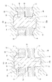
- FIG. 2 is an enlarged view of a part in FIG. (A)
- (B) is sectional drawing which shows the operation
- the perspective view which shows the waveform retainer which is the 2nd example of embodiment of this invention.
- the fragmentary sectional view of the middle assembly of the wavelike holder which is the 2nd example of the embodiment of the present invention.
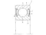
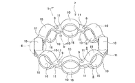
- FIG. 1 is a half sectional view of a ball bearing incorporating a corrugated cage to which the present invention is applied. Similarly, the perspective view which takes out and shows a waveform holder.
- the expanded bb sectional view of FIG. FIG. 14 is a partial cross-sectional view of an intermediate assembly configured in a conventional manufacturing process.
- (A) And (B) is a structure of the prior invention which press-fits a rivet in a through-hole, and is sectional drawing which shows the operation
- First Example of Embodiment 1 to 3 show an example of the embodiment of the present invention.
- the feature of this embodiment is that the flat plate portions 11a and 11b are arranged in a state in which the flat plate portions 11a and 11b respectively provided in plural on a pair of retainer elements 8a and 8b constituting the waveform retainer are superimposed on each other.
- the structure and function of the other parts, including the shape and structure of the entire waveform holder, are the same as those of general waveform holders known in the prior art, including the structures shown in FIGS.
- the overlapping illustration and description will be omitted or simplified, and the following description will be focused on the features of this example.
- the general waveform holder which is the subject of this example, has the opening widths at both ends of each pocket in the completed state, respectively, more than the diameter of the ball to be held in each pocket. Say what is getting smaller.
- the pair of cage elements 8a and 8b are made of a metal plate which can be nitrided, such as a steel plate or a stainless steel plate, and have the same shape and size.
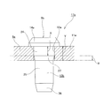
- the through holes 12a and 12b provided in the flat plate portions 11a and 11b are merely simple. It is a circular hole. That is, the inner peripheral surfaces of the through holes 12a and 12b are merely cylindrical surfaces.
- each rivet 9b, 9b is made of a metal that can be nitrided, such as steel, stainless steel or the like.
- the ridge portions 13b and 13b of the rivets 9b and 9b are formed.
- a cylindrical press-fit portion 24 constituting the base end portion and a substantially cylindrical non-press-fit portion 25 having a diameter smaller than that of the press-fit portion 24 constituting the distal end portion and the middle portion are arranged concentrically.
- the press-fit portion 24 can be press-fit into each through hole 12a, 12a of one of the pair of cage elements 8a, 8b.
- the axial dimension X of the press-fit portion 24 is smaller (X ⁇ Y) than the axial dimension Y of each through hole 12a, 12a.
- the axially intermediate portion is a mere cylindrical surface.
- the distal end portion and the proximal end portion of the non-press-in portion 25 are partially conical guide surfaces 26 and 27 inclined in a direction in which the diameter decreases toward the distal end side.
- Each guide surface 26, 27 plays a role of facilitating the insertion of the collar 13 b into each through hole 12 a, 12 a.
- the intermediate assembly 17a In the state where the intermediate assembly 17a is configured, the outer peripheral surfaces of the non-press-in portions 25, 25 of the rivets 9b, 9b are not in contact with the inner peripheral surfaces of the through holes 12a, 12a. Then, in this state, the intermediate assembly 17a is nitrided. As a result, a nitrided layer is formed on the surface of each of the rivets 9b, 9b and one of the retainer elements 8a where the rivets 9b, 9b are not in contact with the one of the retainer elements 8a. At the same time, the other holder element 8b of the pair of holder elements 8a and 8b is nitrided in a single state.
- a nitrided layer is formed on the entire surface of the other cage element 8b.
- various kinds of conventionally known ones such as those described in Patent Document 1 can be adopted.
- each rivet 9 b is formed from the both sides in the axial direction between the bottom surfaces of the concave portions 21 and 21 of the pair of caulking molds 20 and 20.
- the tip end of the collar 13b of each rivet 9b is crushed to form a crimped portion 15a.
- the flat plate portions 11a and 11b of the two cage elements 8a and 8b, which are superimposed on each other, are joined by being held between the head portion 14a of each rivet 9b and the caulking portion 15a to complete the waveform cage. .
- the intermediate assembly 17a formed by temporarily fixing the rivets 9b and 9b to one holder element 8a is subjected to nitriding treatment. Because of this, it is possible to dispense with a dedicated nitriding process for each rivet 9b, 9b. Moreover, in a state where the intermediate assembly 17a is configured, the rivets 9b, 9b are press-fitted into the respective through holes 12a, 12a by the respective press-fit portions 24, 24 so that axial directions with respect to the respective through holes 12a, 12a are obtained.
- the axial dimension X of the press-fit portions 24, 24 of the rivets 9b, 9b is smaller than the axial dimension Y of the through holes 12a, 12a of one retainer element 8a (X ⁇ Y)
- X ⁇ Y the axial dimension of the through holes 12a, 12a of one retainer element 8a
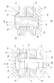
- the axial dimension X of the press-fit portions 24, 24 of the rivets 9b, 9b is smaller than the axial dimension Y of the through holes 12a, 12a of one retainer element 8a (X Since each of the press-fit portions 24 and 24 forms the inner end opening of each through hole 12a and 12a in the state where the intermediate assembly 17a is configured, the inner side surface of each flat plate portion 11a and 11a (FIG. It does not protrude outside through the opening on the lower side of 3). For this reason, as shown in the order of (A) ⁇ (B) of FIG.
- the reason for restricting in the range of X ⁇ 0.50Y is preferable because the fitting length between each through hole 12a, 12a and each flange portion 13b, 13b is secured, and each length for each through hole 12a, 12a is fixed. This is to make it easy to sufficiently secure the retaining force of the rivets 9b, 9b.
- the nitrided layer can be reliably formed on the inner side surfaces of the respective head portions 14a and 14a opposed to each other and a part of the outer side surfaces of the flat portions 11a and 11a.
- an operation of bringing the inner side surfaces of the head portions 14a and 14a into contact with the outer side surfaces of the flat plate portions 11a and 11a is performed. If this operation is performed simultaneously with the formation of the caulking portion 15a, the number of manufacturing steps can be increased.
- FIG. 4 shows a perspective view of a second example of a wave type holder according to an embodiment of the present invention
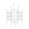
- FIG. 5 shows a partial cross sectional view of an intermediate assembly of the wave type holder.
- the feature of this example is that the shape of each through hole 12a of one of the pair of cage elements 8 and 8a constituting the cage is devised.
- the manufacturing method and the structure other than this feature portion are substantially the same as the manufacturing method and the structure of the above-mentioned corrugated carrier according to the above-mentioned invention, or the manufacturing method and the structure of the conventionally known corrugated cage.
- the general waveform holder which is the subject of this example, has the opening widths at both ends of each pocket in the completed state, respectively, more than the diameter of the ball to be held in each pocket. Say what is getting smaller.
- the waveform retainer 7a of this embodiment joins a pair of retainer elements 8 and 8a and a pair of retainer elements 8 and 8a to each other. It consists of a plurality of rivets 9a, 9a for carrying out.
- Each of the rivets 9a and 9a is the same as the rivet 9a of the conventional structure, and is made of a metal that can be nitrided, such as steel or stainless steel, and is provided at the ridge 13a and the proximal end of the ridge 13a.
- the collar portions 13a, 13a are composed of a large diameter portion 18 on the proximal side and a small diameter portion 19 on the distal side.
- a pair of cage elements 8 and 8a are formed into a corrugated annular shape by punching and bending a material such as a steel plate or stainless steel plate made of a metal plate capable of being nitrided, such as a steel plate or stainless steel plate. ing.
- a material such as a steel plate or stainless steel plate made of a metal plate capable of being nitrided, such as a steel plate or stainless steel plate.
- one cage element 8a has the partially spherical curved plate portions 10 at a plurality of locations in the circumferential direction and the curved plate portions 10 adjacent to each other in the circumferential direction. Between the flat plate portions 11a and 11a, through holes 12a are provided at circumferentially central portions of the flat plate portions 11a and 11a.
- the other cage element 8 is the same as the cage element 8 of the conventional structure, and the partially spherical curved plates 10, 10 are arranged at a plurality of locations in the circumferential direction, and the curved plates 10, 10 are circumferentially adjacent to each other.
- the flat plate portions 11 and 11 are provided between each other, and a through hole 12 is provided at the circumferential direction central portion of each of the flat plate portions 11 and 11.
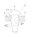
- Each through hole 12a formed in each flat plate portion 11a of one cage element 8a of the pair of cage elements 8 and 8a is axially outside (the other cage element 8 as shown in FIG. 5).
- the small diameter hole 28 on the opposite side) and the inner diameter in the axial direction (the side of the other cage element 8) is a two-step hole consisting of a large diameter hole 29.
- the inner diameter d 29 of the large diameter hole 29 is larger than the outer diameter D 18 of the large diameter portion 18 (d 29 > D 18 ), and the press dimensional relationship is not satisfied. Therefore, in a state where the large diameter portion 18 of the rivet 9a is press-fit into the small diameter hole 28, a gap 22 is formed between the large diameter hole 29 and the outer peripheral surface of the large diameter portion 18 of the rivet 9a.
- the through holes 12a can be formed by press punching, and can be formed in the same process as the conventional processing process.
- the intermediate assembly 17a shown in FIG. 5 is assembled in the same manner as the aforementioned invention. Specifically, the head 14 of the rivet 9a is disposed on the axially outer side (the opposite side of the other cage element 8) of one cage element 8a of the pair of cage elements 8 and 8a, and the large diameter The portion 18 is press-fit into the small diameter holes 28 of each through hole 12a. However, at this time, the head portion 14 of the rivet 9a is not in close contact with the flat plate portion 11a, and is press-fitted in a slightly floating state.
- a gap 22 is formed between the large diameter hole 29 of the through hole 12a and the outer peripheral surface of the large diameter portion 18 of the rivet 9a, and between the head 14 of the rivet 9a and the flat portion 11a. , The gap 30 is formed. Then, the intermediate assembly 17a configured as described above is nitrided. On the other hand, the other holder element 8 of the both holder elements 8 and 8a is nitrided in a single state.
- a nitride layer is formed on the entire circumferential surface of the other holder element 8.
- the intermediate assembly 17a since the small diameter hole 28 of the through hole 12a and the large diameter portion 18 of the rivet 9a are press-fit fitted, no nitrided layer is formed in this portion, but the head of the rivet 9a A gap 30 is formed between the flat plate portion 11a and the flat plate portion 11a, and a gap 22 is formed between the large diameter hole 29 of the through hole 12a and the outer peripheral surface of the large diameter portion 18 of the rivet 9a. Therefore, a nitrided layer is formed in the portion.
- the flange portion 13a of the rivet 9a receives an axial pressing force, and is radially outward on the inner side of the through holes 12, 12a of the pair of cage elements 8, 8a. Plastically deforms as it expands. By plastically deforming the rivets 9a in this manner, part or all of the gaps existing between the outer peripheral surface of each rivet 9 and the inner peripheral surfaces of the through holes 12 and 12a including the gaps 22 disappear. As a result, both the holder elements 8 and 8a and the ridge portion 13 of each rivet 9a are fixed without rattling.
- the intermediate assembly 17a forms the gap 30 between the head 14 of the rivet 9a and the flat plate portion 11a, but it is difficult to eliminate the gap 30 in the caulking process or the like, or There is no need to provide the gap 30, for example, when the
- each penetration of one holder element 8a A nitrided layer is formed on the inner peripheral surface of the hole 12 a and a part of the outer peripheral surface of the large diameter portion 18 of each rivet 9 to realize a structure excellent in durability.
- each pocket 16 which comprises the general waveform holder 7 is smaller than the diameter of the ball 6 which should be hold
- the pair of holder elements 8 is used. , 8a, it is necessary to hold the balls 6, 6 between the inner surfaces of the curved plate portions 10, 10, respectively.
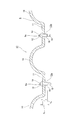
- FIG. 6 shows a partial cross-sectional view of an intermediate assembly 17b of a waveform holder which is a third example of the embodiment of the present invention.
- One cage element 8b of the present embodiment differs from the one cage element 8a of the second example of the embodiment only in the shape of the through hole 12b formed in the flat plate portion 11b.
- the other configuration is the same as that of the second example of the embodiment, so the description will be omitted.
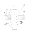
- Each through hole 12b formed in each flat plate portion 11b of one cage element 8b has an axially outer side (opposite to the other cage element 8) and an axially inner side (the other) as shown in FIG. (The side of the cage element 8 of FIG. 1) comprises a tapered hole 29a. Because the inner diameter d 28 of the small-diameter hole 28, the outer diameter D 18 of the cylindrical large-diameter portion 18 provided in the head 14 near portion of the rod portion 13a of the rivet 9a is clearance fit, or, if the intermediate There is a dimensional relationship that On the other hand, the tapered hole 29a is a tapered hole whose diameter gradually increases from the small diameter hole 28 toward the inner side in the axial direction (the side of the other cage element 8).
- the method for manufacturing a waveform holder and the waveform holder according to the present invention can perform the nitriding treatment of each member constituting the waveform holder at low cost and can improve the handleability of the intermediate assembly.
- the area of the portion where the nitriding treatment is not performed (the nitrided layer is not formed) can be reduced to the minimum, the durability of the completed wave cage can be improved. Therefore, for example, as a wave ball holder for holding balls, which constitutes various rolling bearings incorporated in the rotary support of various mechanical devices such as radial ball bearings, automobiles, general industrial machines, machine tools, etc., and a manufacturing method thereof It can be suitably adopted.
- the manufacturing method of the waveform holder and the waveform holder of the present invention is not limited to the general waveform holder described above, and only one opening width among the opening widths at both ends of each pocket is in each pocket It is also possible to implement for special corrugated cages which are smaller than the diameter of the balls to be held and whose other opening width is larger than the diameter of each ball.
Landscapes
- Engineering & Computer Science (AREA)
- General Engineering & Computer Science (AREA)
- Mechanical Engineering (AREA)
- Rolling Contact Bearings (AREA)
- Connection Of Plates (AREA)
- Insertion Pins And Rivets (AREA)
Abstract
Description
(1) 1対の保持器素子と、複数のリベットとを備え、
前記1対の保持器素子はそれぞれ、窒化処理可能な金属板により全体を波形の円環状に造られて、円周方向複数箇所に略部分球殻状の曲板部を、円周方向に隣り合う前記曲板部同士の間に平板部を、各前記平板部の一部に貫通孔を、それぞれ備えており、
各前記リベットはそれぞれ、窒化処理可能な金属製で、杆部と、前記杆部の基端部に設けられた頭部とを備えており、
前記1対の保持器素子の各前記平板部同士を互いに重ね合わせると共に、互いに重ね合わせた各前記平板部の前記貫通孔に各前記リベットの前記杆部を挿通した状態で、各前記杆部の先端部を押し潰してかしめ部を形成し、互いに重ね合わせた各前記平板部同士を各前記リベットの前記頭部と前記かしめ部とで挟持する事により接合して、各前記曲板部に囲まれた部分を、それぞれ玉を転動自在に保持する為のポケットとする波形保持器の製造方法であって、
前記かしめ部を形成する以前の状態で、各前記リベットの前記杆部の前記基端部に、その軸方向寸法が前記1対の保持器素子のうちの一方の保持器素子の各前記貫通孔の軸方向寸法よりも小さく、且つ、各前記貫通孔に圧入可能な圧入部を設けると共に、各前記リベットの杆部の残部に、各前記貫通孔に前記圧入部を圧入した状態で、各前記貫通孔に対して非接触になる非圧入部を設けており、
各前記リベットの前記圧入部を前記一方の保持器素子の各前記貫通孔に圧入する事により、各前記リベットを前記一方の保持器素子に仮止めして成る中間組立体を構成した状態で、前記中間組立体に対して窒化処理を施すと共に、
前記1対の保持器素子のうちの他方の保持器素子に対して、単体の状態で窒化処理を施した後、
前記中間組立体を構成する各前記リベットの前記杆部のうち前記一方の保持器素子の各前記貫通孔から突出した部分を前記他方の保持器素子の各前記貫通孔に挿通すると共に、前記1対の保持器素子の前記平板部同士を重ね合わせた状態で前記かしめ部を形成する
事を特徴とする波形保持器の製造方法。
(2) 各前記リベットの前記圧入部の軸方向寸法をXとし、前記一方の保持器素子の各前記貫通孔の軸方向寸法をYとした場合に、X=(0.50~0.90)Yとする
事を特徴とする(1)に記載した波形保持器の製造方法。
(3) 1対の保持器素子と、複数のリベットとを備え、
前記1対の保持器素子はそれぞれ、窒化処理可能な金属板により全体を波形の円環状に造られて、円周方向複数箇所に略部分球殻状の曲板部を、円周方向に隣り合う前記曲板部同士の間に平板部を、各前記平板部の一部に貫通孔を、それぞれ備えており、
各前記リベットはそれぞれ、窒化処理可能な金属製で、杆部と、前記杆部の基端部に設けられた頭部とを備えており、
前記1対の保持器素子の各前記平板部同士を互いに重ね合わせると共に、互いに重ね合わせた各前記平板部の前記貫通孔に各前記リベットの前記杆部を挿通した状態で、各前記杆部の先端部を押し潰してかしめ部を形成し、互いに重ね合わせた各前記平板部同士を各前記リベットの前記頭部と前記かしめ部とで挟持する事により接合して、各前記曲板部に囲まれた部分を、それぞれ玉を転動自在に保持する為のポケットとした波形保持器であって、
前記かしめ部を形成する以前の状態での各前記リベットは、前記杆部の前記基端部に、その軸方向寸法が前記1対の保持器素子のうちの一方の保持器素子の各前記貫通孔の軸方向寸法よりも小さく、且つ、各前記貫通孔に圧入可能な圧入部が設けられていると共に、前記杆部の残部に、各前記貫通孔に前記圧入部を圧入した状態で、各前記貫通孔に対して非接触になる非圧入部が設けられているものであり、
各前記リベットと前記一方の保持器素子とは、各前記リベットの圧入部を、前記一方の保持器素子の各前記貫通孔に圧入する事により、各前記リベットを前記一方の保持器素子に仮止めして成る中間組立体を構成した状態で窒化処理を施されたものであり、
前記1対の保持器素子のうちの他方の保持器素子は、単体の状態で窒化処理を施されたものである
事を特徴とする波形保持器。
(4) 各前記リベットの圧入部の軸方向寸法をXとし、前記一方の保持器素子の各前記貫通孔の軸方向寸法をYとした場合に、X=(0.50~0.90)Yである
事を特徴とする(3)に記載した波形保持器。
(5) 1対の保持器素子と、複数のリベットとを備え、
前記1対の保持器素子はそれぞれ、窒化処理可能な金属板により全体を波形の円環状に造られて、円周方向複数箇所に部分球面状の曲板部を、円周方向に隣り合う前記曲板部同士の間に平板部を、各前記平板部の一部に貫通孔を、それぞれ備えており、
各前記リベットはそれぞれ、窒化処理可能な金属製で、杆部と、前記杆部の基端部に設けられた、前記杆部よりも大径の頭部とを備えており、
前記1対の保持器素子の各前記平板部同士を互いに重ね合わせると共に、互いに重ね合わせた各前記平板部の前記貫通孔に各前記リベットの前記杆部を挿通した状態で、各前記杆部の先端部を押し潰して、各前記杆部よりも大径のかしめ部を形成し、互いに重ね合わせた各前記平板部同士を各前記リベットの前記頭部と前記かしめ部とで挟持する事により接合して、各前記曲板部に囲まれた部分を、それぞれ玉を転動自在に保持する為のポケットとする波形保持器の製造方法であって、
前記1対の保持器素子のうちの一方の保持器素子の各前記貫通孔は、軸方向外側の、前記リベットの前記杆部とすきまばめ、あるいは、中間ばめとなる寸法関係に有る小径穴と、他方の保持器素子側である軸方向内側の、前記リベットの前記杆部との間に隙間を生じる穴とからなり、
前記一方の保持器素子の各前記小径穴と各前記リベットの前記杵部とを圧入嵌合した状態で窒化処理を施すと共に、前記他方の保持器素子に対して、単体のまま窒化処理を施した後、
各前記リベットの前記杆部のうちの前記一方の保持器素子の各前記貫通孔から突出した部分を前記他方の保持器素子の各前記貫通孔に挿通すると共に前記1対の保持器素子の前記平板部同士を重ね合わせた状態で前記リベットの先端部をかしめる事により、前記1対の保持器素子同士を結合固定する
事を特徴とする波形保持器の製造方法。
(6) 1対の保持器素子と、複数のリベットとを備え、
前記1対の保持器素子はそれぞれ、窒化処理可能な金属板により全体を波形の円環状に造られて、円周方向複数箇所に部分球面状の曲板部を、円周方向に隣り合う曲板部同士の間に平板部を、各前記平板部の一部に貫通孔を、それぞれ備えており、
各前記リベットはそれぞれ、窒化処理可能な金属製で、杆部と、前記杆部の基端部に設けられた、前記杆部よりも大径の頭部とを備えており、
前記1対の保持器素子の各前記平板部の内側面同士を互いに突き合わせると共に、互いに突き合わせた各前記平板部の前記貫通孔に各前記リベットの前記杆部を挿通した状態で、各前記杆部の先端部を押し潰して、各前記杆部よりも大径のかしめ部を形成し、互いに突き合わせた各前記平板部同士を各前記リベットの前記頭部と前記かしめ部とで挟持する事により接合して、各前記曲板部に囲まれた部分を、それぞれ玉を転動自在に保持する為のポケットとした波形保持器であって、
前記1対の保持器素子のうちの一方の保持器素子の各前記貫通孔は、軸方向外側の、前記リベットの前記杆部とすきまばめ、あるいは、中間ばめとなる寸法関係に有る小径穴と、他方の保持器素子側である軸方向内側の、前記リベットの前記杆部との間に隙間を生じる穴とからなり、
各前記リベットと前記一方の保持器素子とは、前記一方の保持器素子の各前記小径穴と各前記リベットの前記杵部とを圧入嵌合した状態で窒化処理を施されたものであり、前記1対の保持器素子のうちの他方の保持器素子は、単体のまま窒化処理を施されたものである
事を特徴とする波形保持器。
図1~3は、本発明の実施の形態の1例を示している。尚、本例の特徴は、波形保持器を構成する1対の保持器素子8a、8bにそれぞれ複数ずつ設けた平板部11a、11b同士を互いに重ね合わせた状態で、各平板部11a、11b同士を、リベット9b、9bにより結合固定する部分の構造及びその製造方法にある。波形保持器全体の形状及び構造を含め、その他の部分の構造及び作用は、前述の図7~6に示した構造を含め、従来から知られている一般的な波形保持器と同様であるから、重複する図示並びに説明は、省略若しくは簡略にし、以下、本例の特徴部分を中心に説明する。
尚、本例の対象となる、一般的な波形保持器とは、前述した様に、完成状態で、各ポケットの両端の開口幅が、それぞれこれら各ポケット内に保持すべき玉の直径よりも小さくなっているものを言う。
これに対し、本発明を実施する場合、中間組立体17aに対して窒化処理を施す際に、各頭部14a、14aの内側面と各平板部11a、11aの外側面との間に隙間を設けておけば、互いに対向する各頭部14a、14aの内側面と各平板部11a、11aの外側面の一部とにも、確実に窒化層を形成する事ができる。この場合には、当該窒化処理を行った後に、各頭部14a、14aの内側面と各平板部11a、11aの外側面とを当接させる作業を行う。尚、この作業を、かしめ部15aの形成と同時に行う様にすれば、製造工程を増やさずに済む。
図4は、本発明の実施の形態の第2例の波型保持器の斜視図を示し、図5は、波形保持器の中間組立体の部分断面図を示している。尚、本例の特徴は、保持器を構成する1対の保持器素子8、8aのうちの、一方の保持器素子8aの各貫通孔12aの形状を工夫した点にある。この特徴部分以外の製造方法及び構造は、前述した先発明の波形保持器の製造方法及び構造、或いは、従来から知られている波形保持器の製造方法及び構造とほぼ同様であるから、先発明或いは従来構造と同様に構成する部分に就いては説明を簡略にし、以下、本例の特徴部分を中心に説明する。
尚、本例の対象となる、一般的な波形保持器とは、前述した様に、完成状態で、各ポケットの両端の開口幅が、それぞれこれら各ポケット内に保持すべき玉の直径よりも小さくなっているものを言う。
従って、小径穴28にリベット9aの大径部18を圧入した状態で、この大径穴29と、リベット9aの大径部18の外周面との間に隙間22が形成される。
また、貫通孔12aは、プレス打ち抜き加工にて成形可能であり、従来の加工工程と同じ工程で成形することができる。
先ず、前述した先発明と同様に、図5に示した中間組立体17aを組み立てる。具体的には、一対保持器素子8、8aのうち、一方の保持器素子8aの軸方向外側(他方の保持器素子8の反対側)にリベット9aの頭部14を配置すると共に、大径部18を、各貫通孔12aの小径穴28に圧入する。但し、このとき、リベット9aの頭部14は、平板部11aに密着させず、少し浮いた状態に圧入する。この状態で、貫通孔12aの大径穴29とリベット9aの大径部18の外周面との間には、隙間22が形成され、リベット9aの頭部14と平板部11aとの間には、隙間30が形成される。次いで、上述の様に構成される中間組立体17aに対して窒化処理を施す。一方、両保持器素子8、8aのうち、他方の保持器素子8には、単体の状態で窒化処理を施す。
これに対し、特殊な例ではあるが、完成後の状態で、各ポケットの両端の開口幅のうち、一方の開口幅のみが、これら各ポケット内に保持すべき玉の直径よりも小さくなっており、他方の開口幅が、これら各玉の直径よりも大きくなっている波形保持器を対象として、上述した本発明の製造方法を実施する場合には、必ずしも、かしめ部を形成する前に1対の保持器素子の曲板部の内面同士の間に各玉を挟み込んでおく必要はない。
図6は、本発明の実施の形態の第3例である波形保持器の中間組立体17bの部分断面図を示している。本実施の形態の一方の保持器素子8bは、実施の形態の第2例の一方の保持器素子8aに対し、平板部11bに形成された貫通孔12bの形状のみ異なる。それ以外の構成は、実施の形態の第2例と同じなので、説明を省略する。
従って、小径穴28にリベット9aの大径部18を圧入した状態で、このテーパー穴29aと、リベット9aの大径部18の外周面との間に隙間22aが形成される。
このような構成をとることにより、実施の形態の第2例の波形保持器7aと同等の効果を得ることが出来る。
したがって、例えば、ラジアル玉軸受等、自動車、一般産業機械、工作機械等の各種機械装置の回転支持部に組み込まれる各種転がり軸受を構成する、玉を保持する波形保持器、及び、その製造方法として好適に採用することができる。
また、本発明の波形保持器の製造方法及び波形保持器は、前述した一般的な波形保持器に限らず、各ポケットの両端の開口幅のうち、一方の開口幅のみが、各ポケット内に保持すべき玉の直径よりも小さくなっており、他方の開口幅が、各玉の直径よりも大きくなっている、特殊な波形保持器を対象として実施する事もできる。
2 内輪軌道
3 内輪
4 外輪軌道
5 外輪
6 玉
7、7a 保持器
8、8a、8b 保持器素子
9、9a、9b リベット
10、10a、10b 曲板部
11、11a、11b 平板部
12、12a、12b 貫通孔
13、13a、13b 杆部
14、14a 頭部
15、15a かしめ部
16 ポケット
17、17a 中間組立体
18 大径部
19 小径部
20 かしめ金型
21 凹部
22 隙間
23 はみ出し部
24 圧入部
25 非圧入部
26 案内面
27 案内面
28 小径穴
29 大径穴
29a テーパー穴
30 隙間
Claims (6)
- 1対の保持器素子と、複数のリベットとを備え、
前記1対の保持器素子はそれぞれ、窒化処理可能な金属板により全体を波形の円環状に造られて、円周方向複数箇所に略部分球殻状の曲板部を、円周方向に隣り合う前記曲板部同士の間に平板部を、各前記平板部の一部に貫通孔を、それぞれ備えており、
各前記リベットはそれぞれ、窒化処理可能な金属製で、杆部と、前記杆部の基端部に設けられた頭部とを備えており、
前記1対の保持器素子の各前記平板部同士を互いに重ね合わせると共に、互いに重ね合わせた各前記平板部の前記貫通孔に各前記リベットの前記杆部を挿通した状態で、各前記杆部の先端部を押し潰してかしめ部を形成し、互いに重ね合わせた各前記平板部同士を各前記リベットの前記頭部と前記かしめ部とで挟持する事により接合して、各前記曲板部に囲まれた部分を、それぞれ玉を転動自在に保持する為のポケットとする波形保持器の製造方法であって、
前記かしめ部を形成する以前の状態で、各前記リベットの前記杆部の前記基端部に、その軸方向寸法が前記1対の保持器素子のうちの一方の保持器素子の各前記貫通孔の軸方向寸法よりも小さく、且つ、各前記貫通孔に圧入可能な圧入部を設けると共に、各前記リベットの杆部の残部に、各前記貫通孔に前記圧入部を圧入した状態で、各前記貫通孔に対して非接触になる非圧入部を設けており、
各前記リベットの前記圧入部を前記一方の保持器素子の各前記貫通孔に圧入する事により、各前記リベットを前記一方の保持器素子に仮止めして成る中間組立体を構成した状態で、前記中間組立体に対して窒化処理を施すと共に、
前記1対の保持器素子のうちの他方の保持器素子に対して、単体の状態で窒化処理を施した後、
前記中間組立体を構成する各前記リベットの前記杆部のうち前記一方の保持器素子の各前記貫通孔から突出した部分を前記他方の保持器素子の各前記貫通孔に挿通すると共に、前記1対の保持器素子の前記平板部同士を重ね合わせた状態で前記かしめ部を形成する
事を特徴とする波形保持器の製造方法。 - 各前記リベットの前記圧入部の軸方向寸法をXとし、前記一方の保持器素子の各前記貫通孔の軸方向寸法をYとした場合に、X=(0.50~0.90)Yとする
事を特徴とする請求項1に記載した波形保持器の製造方法。 - 1対の保持器素子と、複数のリベットとを備え、
前記1対の保持器素子はそれぞれ、窒化処理可能な金属板により全体を波形の円環状に造られて、円周方向複数箇所に略部分球殻状の曲板部を、円周方向に隣り合う前記曲板部同士の間に平板部を、各前記平板部の一部に貫通孔を、それぞれ備えており、
各前記リベットはそれぞれ、窒化処理可能な金属製で、杆部と、前記杆部の基端部に設けられた頭部とを備えており、
前記1対の保持器素子の各前記平板部同士を互いに重ね合わせると共に、互いに重ね合わせた各前記平板部の前記貫通孔に各前記リベットの前記杆部を挿通した状態で、各前記杆部の先端部を押し潰してかしめ部を形成し、互いに重ね合わせた各前記平板部同士を各前記リベットの前記頭部と前記かしめ部とで挟持する事により接合して、各前記曲板部に囲まれた部分を、それぞれ玉を転動自在に保持する為のポケットとした波形保持器であって、
前記かしめ部を形成する以前の状態での各前記リベットは、前記杆部の前記基端部に、その軸方向寸法が前記1対の保持器素子のうちの一方の保持器素子の各前記貫通孔の軸方向寸法よりも小さく、且つ、各前記貫通孔に圧入可能な圧入部が設けられていると共に、前記杆部の残部に、各前記貫通孔に前記圧入部を圧入した状態で、各前記貫通孔に対して非接触になる非圧入部が設けられているものであり、
各前記リベットと前記一方の保持器素子とは、各前記リベットの圧入部を、前記一方の保持器素子の各前記貫通孔に圧入する事により、各前記リベットを前記一方の保持器素子に仮止めして成る中間組立体を構成した状態で窒化処理を施されたものであり、
前記1対の保持器素子のうちの他方の保持器素子は、単体の状態で窒化処理を施されたものである
事を特徴とする波形保持器。 - 各前記リベットの圧入部の軸方向寸法をXとし、前記一方の保持器素子の各前記貫通孔の軸方向寸法をYとした場合に、X=(0.50~0.90)Yである
事を特徴とする請求項3に記載した波形保持器。 - 1対の保持器素子と、複数のリベットとを備え、
前記1対の保持器素子はそれぞれ、窒化処理可能な金属板により全体を波形の円環状に造られて、円周方向複数箇所に部分球面状の曲板部を、円周方向に隣り合う前記曲板部同士の間に平板部を、各前記平板部の一部に貫通孔を、それぞれ備えており、
各前記リベットはそれぞれ、窒化処理可能な金属製で、杆部と、前記杆部の基端部に設けられた、前記杆部よりも大径の頭部とを備えており、
前記1対の保持器素子の各前記平板部同士を互いに重ね合わせると共に、互いに重ね合わせた各前記平板部の前記貫通孔に各前記リベットの前記杆部を挿通した状態で、各前記杆部の先端部を押し潰して、各前記杆部よりも大径のかしめ部を形成し、互いに重ね合わせた各前記平板部同士を各前記リベットの前記頭部と前記かしめ部とで挟持する事により接合して、各前記曲板部に囲まれた部分を、それぞれ玉を転動自在に保持する為のポケットとする波形保持器の製造方法であって、
前記1対の保持器素子のうちの一方の保持器素子の各前記貫通孔は、軸方向外側の、前記リベットの前記杆部とすきまばめ、あるいは、中間ばめとなる寸法関係に有る小径穴と、他方の保持器素子側である軸方向内側の、前記リベットの前記杆部との間に隙間を生じる穴とからなり、
前記一方の保持器素子の各前記小径穴と各前記リベットの前記杵部とを圧入嵌合した状態で窒化処理を施すと共に、前記他方の保持器素子に対して、単体のまま窒化処理を施した後、
各前記リベットの前記杆部のうちの前記一方の保持器素子の各前記貫通孔から突出した部分を前記他方の保持器素子の各前記貫通孔に挿通すると共に前記1対の保持器素子の前記平板部同士を重ね合わせた状態で前記リベットの先端部をかしめる事により、前記1対の保持器素子同士を結合固定する
事を特徴とする波形保持器の製造方法。 - 1対の保持器素子と、複数のリベットとを備え、
前記1対の保持器素子はそれぞれ、窒化処理可能な金属板により全体を波形の円環状に造られて、円周方向複数箇所に部分球面状の曲板部を、円周方向に隣り合う曲板部同士の間に平板部を、各前記平板部の一部に貫通孔を、それぞれ備えており、
各前記リベットはそれぞれ、窒化処理可能な金属製で、杆部と、前記杆部の基端部に設けられた、前記杆部よりも大径の頭部とを備えており、
前記1対の保持器素子の各前記平板部の内側面同士を互いに突き合わせると共に、互いに突き合わせた各前記平板部の前記貫通孔に各前記リベットの前記杆部を挿通した状態で、各前記杆部の先端部を押し潰して、各前記杆部よりも大径のかしめ部を形成し、互いに突き合わせた各前記平板部同士を各前記リベットの前記頭部と前記かしめ部とで挟持する事により接合して、各前記曲板部に囲まれた部分を、それぞれ玉を転動自在に保持する為のポケットとした波形保持器であって、
前記1対の保持器素子のうちの一方の保持器素子の各前記貫通孔は、軸方向外側の、前記リベットの前記杆部とすきまばめ、あるいは、中間ばめとなる寸法関係に有る小径穴と、他方の保持器素子側である軸方向内側の、前記リベットの前記杆部との間に隙間を生じる穴とからなり、
各前記リベットと前記一方の保持器素子とは、前記一方の保持器素子の各前記小径穴と各前記リベットの前記杵部とを圧入嵌合した状態で窒化処理を施されたものであり、前記1対の保持器素子のうちの他方の保持器素子は、単体のまま窒化処理を施されたものである
事を特徴とする波形保持器。
Priority Applications (5)
| Application Number | Priority Date | Filing Date | Title |
|---|---|---|---|
| EP14817494.9A EP3015726B1 (en) | 2013-06-27 | 2014-06-09 | Method for manufacturing corrugated cage and corrugated cage |
| KR1020157035905A KR101832582B1 (ko) | 2013-06-27 | 2014-06-09 | 파형 유지기의 제조 방법 및 파형 유지기 |
| CN201480036302.2A CN105339690B (zh) | 2013-06-27 | 2014-06-09 | 波形保持架的制造方法和波形保持架 |
| JP2015523960A JP6098720B2 (ja) | 2013-06-27 | 2014-06-09 | 波形保持器の製造方法及び波形保持器並びに波形保持器のかしめ前の構成部品 |
| US14/392,269 US9624976B2 (en) | 2013-06-27 | 2014-06-09 | Method of manufacturing corrugated cage and corrugated cage |
Applications Claiming Priority (6)
| Application Number | Priority Date | Filing Date | Title |
|---|---|---|---|
| JP2013-134424 | 2013-06-27 | ||
| JP2013134424 | 2013-06-27 | ||
| JP2013206215 | 2013-10-01 | ||
| JP2013-206215 | 2013-10-01 | ||
| JP2013-271393 | 2013-12-27 | ||
| JP2013271393 | 2013-12-27 |
Publications (1)
| Publication Number | Publication Date |
|---|---|
| WO2014208325A1 true WO2014208325A1 (ja) | 2014-12-31 |
Family
ID=52141670
Family Applications (1)
| Application Number | Title | Priority Date | Filing Date |
|---|---|---|---|
| PCT/JP2014/065271 Ceased WO2014208325A1 (ja) | 2013-06-27 | 2014-06-09 | 波形保持器の製造方法及び波形保持器 |
Country Status (6)
| Country | Link |
|---|---|
| US (1) | US9624976B2 (ja) |
| EP (1) | EP3015726B1 (ja) |
| JP (1) | JP6098720B2 (ja) |
| KR (1) | KR101832582B1 (ja) |
| CN (1) | CN105339690B (ja) |
| WO (1) | WO2014208325A1 (ja) |
Cited By (3)
| Publication number | Priority date | Publication date | Assignee | Title |
|---|---|---|---|---|
| CN113290197A (zh) * | 2021-06-01 | 2021-08-24 | 八环科技集团股份有限公司 | 一种保持架铆接工艺及电动涡旋压缩机轴承 |
| WO2023149390A1 (ja) * | 2022-02-04 | 2023-08-10 | Ntn株式会社 | 玉軸受 |
| WO2023210576A1 (ja) * | 2022-04-28 | 2023-11-02 | Ntn株式会社 | 玉軸受 |
Families Citing this family (6)
| Publication number | Priority date | Publication date | Assignee | Title |
|---|---|---|---|---|
| DE102013111584A1 (de) | 2013-10-21 | 2015-05-07 | Federal-Mogul Bremsbelag Gmbh | Trägerkörper für einen Bremsbelag einer Scheibenbremse mit Tilgermasse zur Veränderung der Schwingung |
| DE102013111594B4 (de) * | 2013-10-21 | 2015-04-30 | Federal-Mogul Bremsbelag Gmbh | Verfahren zur Herstellung eines Trägerkörpers mit Tilgermasse zur Veränderung der Schwingung für einen Bremsbelag einer Scheibenbremse |
| DE102014215229A1 (de) * | 2014-08-01 | 2016-02-04 | Zf Friedrichshafen Ag | Baugruppenträger und Baugruppe |
| JP2022147350A (ja) * | 2021-03-23 | 2022-10-06 | Ntn株式会社 | 波形保持器の製造方法 |
| JP7212738B1 (ja) * | 2021-09-21 | 2023-01-25 | Ntn株式会社 | 玉軸受 |
| DE102023107817A1 (de) * | 2023-03-28 | 2024-10-02 | Schaeffler Technologies AG & Co. KG | Käfig, Wälzlager, Verfahren zur Herstellung eines Käfigs und Umformwerkzeug |
Citations (4)
| Publication number | Priority date | Publication date | Assignee | Title |
|---|---|---|---|---|
| JPS5780725U (ja) * | 1980-11-04 | 1982-05-19 | ||
| JPH0547545U (ja) * | 1991-12-03 | 1993-06-25 | 光洋精工株式会社 | 玉軸受用波形保持器 |
| JPH10281163A (ja) | 1997-04-03 | 1998-10-20 | Koyo Seiko Co Ltd | 軸受用保持器ならびにその製造方法 |
| JP2009008164A (ja) * | 2007-06-28 | 2009-01-15 | Nsk Ltd | 保持器製造方法及び保持器並びに転がり軸受 |
Family Cites Families (7)
| Publication number | Priority date | Publication date | Assignee | Title |
|---|---|---|---|---|
| US3471208A (en) * | 1967-10-09 | 1969-10-07 | Textron Inc | Positive alignment feature for split ring bearing retainers |
| JPS5117381Y2 (ja) * | 1971-07-17 | 1976-05-11 | ||
| JPS5230428Y2 (ja) * | 1972-09-07 | 1977-07-12 | ||
| JPS5343957Y2 (ja) * | 1974-09-14 | 1978-10-21 | ||
| JPS57104015U (ja) * | 1980-12-18 | 1982-06-26 | ||
| JPH102336A (ja) * | 1996-04-16 | 1998-01-06 | Koyo Seiko Co Ltd | 軸受用保持器とその製造方法 |
| JP3682356B2 (ja) * | 1997-02-28 | 2005-08-10 | 光洋精工株式会社 | 波形保持器を用いた玉軸受 |
-
2014
- 2014-06-09 KR KR1020157035905A patent/KR101832582B1/ko active Active
- 2014-06-09 EP EP14817494.9A patent/EP3015726B1/en active Active
- 2014-06-09 JP JP2015523960A patent/JP6098720B2/ja active Active
- 2014-06-09 WO PCT/JP2014/065271 patent/WO2014208325A1/ja not_active Ceased
- 2014-06-09 US US14/392,269 patent/US9624976B2/en active Active
- 2014-06-09 CN CN201480036302.2A patent/CN105339690B/zh active Active
Patent Citations (4)
| Publication number | Priority date | Publication date | Assignee | Title |
|---|---|---|---|---|
| JPS5780725U (ja) * | 1980-11-04 | 1982-05-19 | ||
| JPH0547545U (ja) * | 1991-12-03 | 1993-06-25 | 光洋精工株式会社 | 玉軸受用波形保持器 |
| JPH10281163A (ja) | 1997-04-03 | 1998-10-20 | Koyo Seiko Co Ltd | 軸受用保持器ならびにその製造方法 |
| JP2009008164A (ja) * | 2007-06-28 | 2009-01-15 | Nsk Ltd | 保持器製造方法及び保持器並びに転がり軸受 |
Cited By (4)
| Publication number | Priority date | Publication date | Assignee | Title |
|---|---|---|---|---|
| CN113290197A (zh) * | 2021-06-01 | 2021-08-24 | 八环科技集团股份有限公司 | 一种保持架铆接工艺及电动涡旋压缩机轴承 |
| WO2023149390A1 (ja) * | 2022-02-04 | 2023-08-10 | Ntn株式会社 | 玉軸受 |
| WO2023210576A1 (ja) * | 2022-04-28 | 2023-11-02 | Ntn株式会社 | 玉軸受 |
| EP4517122A4 (en) * | 2022-04-28 | 2025-07-30 | Ntn Toyo Bearing Co Ltd | BALL BEARINGS |
Also Published As
| Publication number | Publication date |
|---|---|
| KR20160011213A (ko) | 2016-01-29 |
| US9624976B2 (en) | 2017-04-18 |
| JPWO2014208325A1 (ja) | 2017-02-23 |
| EP3015726A1 (en) | 2016-05-04 |
| JP6098720B2 (ja) | 2017-03-22 |
| US20160298684A1 (en) | 2016-10-13 |
| EP3015726B1 (en) | 2017-11-15 |
| KR101832582B1 (ko) | 2018-02-26 |
| CN105339690A (zh) | 2016-02-17 |
| CN105339690B (zh) | 2017-12-29 |
| EP3015726A4 (en) | 2016-06-15 |
Similar Documents
| Publication | Publication Date | Title |
|---|---|---|
| WO2014208325A1 (ja) | 波形保持器の製造方法及び波形保持器 | |
| JP2023082885A (ja) | 玉軸受 | |
| US9404541B2 (en) | Mating connection for connecting two components in a non-rotatable way and method | |
| JP5466100B2 (ja) | 円すいころ軸受 | |
| JP2007271045A (ja) | 車輪用転がり軸受装置の製造方法 | |
| JP2005090740A (ja) | ころ軸受用保持器の製造方法及びころ軸受用保持器 | |
| JP2016223505A (ja) | ラジアル玉軸受 | |
| JP4967855B2 (ja) | 保持器製造方法及び保持器並びに転がり軸受 | |
| JPWO2019026358A1 (ja) | ハブユニット軸受およびその製造方法、並びに、自動車およびその製造方法 | |
| JP7009821B2 (ja) | 転がり軸受及び保持器 | |
| JP2015044220A (ja) | 波形保持器の製造方法及び波形保持器 | |
| JP2015031359A (ja) | 保持器、円錐ころ軸受及び円錐ころ軸受の製造方法 | |
| JP2015064100A (ja) | 波形保持器の製造方法及び波形保持器 | |
| JP4811056B2 (ja) | ころ軸受及び円錐ころ軸受の製造方法 | |
| JP2015045371A (ja) | 波形保持器の製造方法及び波形保持器 | |
| US20250146530A1 (en) | Ball bearing | |
| US20250277510A1 (en) | Ball bearing | |
| JP2015203438A (ja) | 波形保持器の製造方法及び波形保持器 | |
| JP7212738B1 (ja) | 玉軸受 | |
| JP2009168180A (ja) | ころ軸受用保持器 | |
| JP2017150584A (ja) | 玉軸受 | |
| JP2024150118A (ja) | 波形保持器 | |
| JP2015137684A (ja) | 玉軸受用保持器の製造方法及び玉軸受用保持器 | |
| JP2018044596A (ja) | 円錐ころ軸受の製造方法 | |
| JP2015148278A (ja) | スラストニードル軸受用保持器及びスラストニードル軸受 |
Legal Events
| Date | Code | Title | Description |
|---|---|---|---|
| WWE | Wipo information: entry into national phase |
Ref document number: 201480036302.2 Country of ref document: CN |
|
| 121 | Ep: the epo has been informed by wipo that ep was designated in this application |
Ref document number: 14817494 Country of ref document: EP Kind code of ref document: A1 |
|
| ENP | Entry into the national phase |
Ref document number: 2015523960 Country of ref document: JP Kind code of ref document: A |
|
| ENP | Entry into the national phase |
Ref document number: 20157035905 Country of ref document: KR Kind code of ref document: A |
|
| REEP | Request for entry into the european phase |
Ref document number: 2014817494 Country of ref document: EP |
|
| WWE | Wipo information: entry into national phase |
Ref document number: 2014817494 Country of ref document: EP |
|
| WWE | Wipo information: entry into national phase |
Ref document number: 14392269 Country of ref document: US |
|
| NENP | Non-entry into the national phase |
Ref country code: DE |