WO2015004865A1 - 積層すべり部材及びこの積層すべり部材を使用したすべり支承 - Google Patents
積層すべり部材及びこの積層すべり部材を使用したすべり支承 Download PDFInfo
- Publication number
- WO2015004865A1 WO2015004865A1 PCT/JP2014/003346 JP2014003346W WO2015004865A1 WO 2015004865 A1 WO2015004865 A1 WO 2015004865A1 JP 2014003346 W JP2014003346 W JP 2014003346W WO 2015004865 A1 WO2015004865 A1 WO 2015004865A1
- Authority
- WO
- WIPO (PCT)
- Prior art keywords
- flat surface
- sliding member
- laminate
- laminated
- solid lubricant
- Prior art date
- Legal status (The legal status is an assumption and is not a legal conclusion. Google has not performed a legal analysis and makes no representation as to the accuracy of the status listed.)
- Ceased
Links
Images








Classifications
-
- E—FIXED CONSTRUCTIONS
- E04—BUILDING
- E04H—BUILDINGS OR LIKE STRUCTURES FOR PARTICULAR PURPOSES; SWIMMING OR SPLASH BATHS OR POOLS; MASTS; FENCING; TENTS OR CANOPIES, IN GENERAL
- E04H9/00—Buildings, groups of buildings or shelters adapted to withstand or provide protection against abnormal external influences, e.g. war-like action, earthquake or extreme climate
- E04H9/02—Buildings, groups of buildings or shelters adapted to withstand or provide protection against abnormal external influences, e.g. war-like action, earthquake or extreme climate withstanding earthquake or sinking of ground
- E04H9/021—Bearing, supporting or connecting constructions specially adapted for such buildings
-
- A—HUMAN NECESSITIES
- A47—FURNITURE; DOMESTIC ARTICLES OR APPLIANCES; COFFEE MILLS; SPICE MILLS; SUCTION CLEANERS IN GENERAL
- A47B—TABLES; DESKS; OFFICE FURNITURE; CABINETS; DRAWERS; GENERAL DETAILS OF FURNITURE
- A47B91/00—Feet for furniture in general
- A47B91/06—Gliders or the like
-
- C—CHEMISTRY; METALLURGY
- C10—PETROLEUM, GAS OR COKE INDUSTRIES; TECHNICAL GASES CONTAINING CARBON MONOXIDE; FUELS; LUBRICANTS; PEAT
- C10M—LUBRICATING COMPOSITIONS; USE OF CHEMICAL SUBSTANCES EITHER ALONE OR AS LUBRICATING INGREDIENTS IN A LUBRICATING COMPOSITION
- C10M101/00—Lubricating compositions characterised by the base-material being a mineral or fatty oil
- C10M101/02—Petroleum fractions
- C10M101/025—Petroleum fractions waxes
-
- C—CHEMISTRY; METALLURGY
- C10—PETROLEUM, GAS OR COKE INDUSTRIES; TECHNICAL GASES CONTAINING CARBON MONOXIDE; FUELS; LUBRICANTS; PEAT
- C10M—LUBRICATING COMPOSITIONS; USE OF CHEMICAL SUBSTANCES EITHER ALONE OR AS LUBRICATING INGREDIENTS IN A LUBRICATING COMPOSITION
- C10M107/00—Lubricating compositions characterised by the base-material being a macromolecular compound
- C10M107/02—Hydrocarbon polymers; Hydrocarbon polymers modified by oxidation
- C10M107/04—Polyethylene
-
- C—CHEMISTRY; METALLURGY
- C10—PETROLEUM, GAS OR COKE INDUSTRIES; TECHNICAL GASES CONTAINING CARBON MONOXIDE; FUELS; LUBRICANTS; PEAT
- C10M—LUBRICATING COMPOSITIONS; USE OF CHEMICAL SUBSTANCES EITHER ALONE OR AS LUBRICATING INGREDIENTS IN A LUBRICATING COMPOSITION
- C10M107/00—Lubricating compositions characterised by the base-material being a macromolecular compound
- C10M107/38—Lubricating compositions characterised by the base-material being a macromolecular compound containing halogen
-
- C—CHEMISTRY; METALLURGY
- C10—PETROLEUM, GAS OR COKE INDUSTRIES; TECHNICAL GASES CONTAINING CARBON MONOXIDE; FUELS; LUBRICANTS; PEAT
- C10M—LUBRICATING COMPOSITIONS; USE OF CHEMICAL SUBSTANCES EITHER ALONE OR AS LUBRICATING INGREDIENTS IN A LUBRICATING COMPOSITION
- C10M111/00—Lubrication compositions characterised by the base-material being a mixture of two or more compounds covered by more than one of the main groups C10M101/00 - C10M109/00, each of these compounds being essential
- C10M111/04—Lubrication compositions characterised by the base-material being a mixture of two or more compounds covered by more than one of the main groups C10M101/00 - C10M109/00, each of these compounds being essential at least one of them being a macromolecular organic compound
-
- C—CHEMISTRY; METALLURGY
- C10—PETROLEUM, GAS OR COKE INDUSTRIES; TECHNICAL GASES CONTAINING CARBON MONOXIDE; FUELS; LUBRICANTS; PEAT
- C10M—LUBRICATING COMPOSITIONS; USE OF CHEMICAL SUBSTANCES EITHER ALONE OR AS LUBRICATING INGREDIENTS IN A LUBRICATING COMPOSITION
- C10M125/00—Lubricating compositions characterised by the additive being an inorganic material
- C10M125/24—Compounds containing phosphorus, arsenic or antimony
-
- C—CHEMISTRY; METALLURGY
- C10—PETROLEUM, GAS OR COKE INDUSTRIES; TECHNICAL GASES CONTAINING CARBON MONOXIDE; FUELS; LUBRICANTS; PEAT
- C10M—LUBRICATING COMPOSITIONS; USE OF CHEMICAL SUBSTANCES EITHER ALONE OR AS LUBRICATING INGREDIENTS IN A LUBRICATING COMPOSITION
- C10M133/00—Lubricating compositions characterised by the additive being an organic non-macromolecular compound containing nitrogen
- C10M133/02—Lubricating compositions characterised by the additive being an organic non-macromolecular compound containing nitrogen having a carbon chain of less than 30 atoms
- C10M133/38—Heterocyclic nitrogen compounds
- C10M133/40—Six-membered ring containing nitrogen and carbon only
- C10M133/42—Triazines
-
- C—CHEMISTRY; METALLURGY
- C10—PETROLEUM, GAS OR COKE INDUSTRIES; TECHNICAL GASES CONTAINING CARBON MONOXIDE; FUELS; LUBRICANTS; PEAT
- C10M—LUBRICATING COMPOSITIONS; USE OF CHEMICAL SUBSTANCES EITHER ALONE OR AS LUBRICATING INGREDIENTS IN A LUBRICATING COMPOSITION
- C10M169/00—Lubricating compositions characterised by containing as components a mixture of at least two types of ingredient selected from base-materials, thickeners or additives, covered by the preceding groups, each of these compounds being essential
- C10M169/04—Mixtures of base-materials and additives
-
- E—FIXED CONSTRUCTIONS
- E01—CONSTRUCTION OF ROADS, RAILWAYS, OR BRIDGES
- E01D—CONSTRUCTION OF BRIDGES, ELEVATED ROADWAYS OR VIADUCTS; ASSEMBLY OF BRIDGES
- E01D19/00—Structural or constructional details of bridges
- E01D19/04—Bearings; Hinges
- E01D19/042—Mechanical bearings
-
- E—FIXED CONSTRUCTIONS
- E01—CONSTRUCTION OF ROADS, RAILWAYS, OR BRIDGES
- E01D—CONSTRUCTION OF BRIDGES, ELEVATED ROADWAYS OR VIADUCTS; ASSEMBLY OF BRIDGES
- E01D19/00—Structural or constructional details of bridges
- E01D19/04—Bearings; Hinges
- E01D19/042—Mechanical bearings
- E01D19/046—Spherical bearings
-
- E—FIXED CONSTRUCTIONS
- E01—CONSTRUCTION OF ROADS, RAILWAYS, OR BRIDGES
- E01D—CONSTRUCTION OF BRIDGES, ELEVATED ROADWAYS OR VIADUCTS; ASSEMBLY OF BRIDGES
- E01D19/00—Structural or constructional details of bridges
- E01D19/04—Bearings; Hinges
- E01D19/042—Mechanical bearings
- E01D19/047—Pot bearings
-
- E—FIXED CONSTRUCTIONS
- E04—BUILDING
- E04B—GENERAL BUILDING CONSTRUCTIONS; WALLS, e.g. PARTITIONS; ROOFS; FLOORS; CEILINGS; INSULATION OR OTHER PROTECTION OF BUILDINGS
- E04B1/00—Constructions in general; Structures which are not restricted either to walls, e.g. partitions, or floors or ceilings or roofs
- E04B1/62—Insulation or other protection; Elements or use of specified material therefor
- E04B1/92—Protection against other undesired influences or dangers
- E04B1/98—Protection against other undesired influences or dangers against vibrations or shocks; against mechanical destruction, e.g. by air-raids
-
- F—MECHANICAL ENGINEERING; LIGHTING; HEATING; WEAPONS; BLASTING
- F16—ENGINEERING ELEMENTS AND UNITS; GENERAL MEASURES FOR PRODUCING AND MAINTAINING EFFECTIVE FUNCTIONING OF MACHINES OR INSTALLATIONS; THERMAL INSULATION IN GENERAL
- F16C—SHAFTS; FLEXIBLE SHAFTS; ELEMENTS OR CRANKSHAFT MECHANISMS; ROTARY BODIES OTHER THAN GEARING ELEMENTS; BEARINGS
- F16C17/00—Sliding-contact bearings for exclusively rotary movement
- F16C17/04—Sliding-contact bearings for exclusively rotary movement for axial load only
-
- F—MECHANICAL ENGINEERING; LIGHTING; HEATING; WEAPONS; BLASTING
- F16—ENGINEERING ELEMENTS AND UNITS; GENERAL MEASURES FOR PRODUCING AND MAINTAINING EFFECTIVE FUNCTIONING OF MACHINES OR INSTALLATIONS; THERMAL INSULATION IN GENERAL
- F16C—SHAFTS; FLEXIBLE SHAFTS; ELEMENTS OR CRANKSHAFT MECHANISMS; ROTARY BODIES OTHER THAN GEARING ELEMENTS; BEARINGS
- F16C33/00—Parts of bearings; Special methods for making bearings or parts thereof
- F16C33/02—Parts of sliding-contact bearings
- F16C33/04—Brasses; Bushes; Linings
- F16C33/06—Sliding surface mainly made of metal
- F16C33/12—Structural composition; Use of special materials or surface treatments, e.g. for rust-proofing
- F16C33/122—Multilayer structures of sleeves, washers or liners
-
- C—CHEMISTRY; METALLURGY
- C10—PETROLEUM, GAS OR COKE INDUSTRIES; TECHNICAL GASES CONTAINING CARBON MONOXIDE; FUELS; LUBRICANTS; PEAT
- C10M—LUBRICATING COMPOSITIONS; USE OF CHEMICAL SUBSTANCES EITHER ALONE OR AS LUBRICATING INGREDIENTS IN A LUBRICATING COMPOSITION
- C10M2201/00—Inorganic compounds or elements as ingredients in lubricant compositions
- C10M2201/085—Phosphorus oxides, acids or salts
-
- C—CHEMISTRY; METALLURGY
- C10—PETROLEUM, GAS OR COKE INDUSTRIES; TECHNICAL GASES CONTAINING CARBON MONOXIDE; FUELS; LUBRICANTS; PEAT
- C10M—LUBRICATING COMPOSITIONS; USE OF CHEMICAL SUBSTANCES EITHER ALONE OR AS LUBRICATING INGREDIENTS IN A LUBRICATING COMPOSITION
- C10M2201/00—Inorganic compounds or elements as ingredients in lubricant compositions
- C10M2201/085—Phosphorus oxides, acids or salts
- C10M2201/0853—Phosphorus oxides, acids or salts used as base material
-
- C—CHEMISTRY; METALLURGY
- C10—PETROLEUM, GAS OR COKE INDUSTRIES; TECHNICAL GASES CONTAINING CARBON MONOXIDE; FUELS; LUBRICANTS; PEAT
- C10M—LUBRICATING COMPOSITIONS; USE OF CHEMICAL SUBSTANCES EITHER ALONE OR AS LUBRICATING INGREDIENTS IN A LUBRICATING COMPOSITION
- C10M2205/00—Organic macromolecular hydrocarbon compounds or fractions, whether or not modified by oxidation as ingredients in lubricant compositions
- C10M2205/14—Synthetic waxes, e.g. polythene waxes
- C10M2205/143—Synthetic waxes, e.g. polythene waxes used as base material
-
- C—CHEMISTRY; METALLURGY
- C10—PETROLEUM, GAS OR COKE INDUSTRIES; TECHNICAL GASES CONTAINING CARBON MONOXIDE; FUELS; LUBRICANTS; PEAT
- C10M—LUBRICATING COMPOSITIONS; USE OF CHEMICAL SUBSTANCES EITHER ALONE OR AS LUBRICATING INGREDIENTS IN A LUBRICATING COMPOSITION
- C10M2205/00—Organic macromolecular hydrocarbon compounds or fractions, whether or not modified by oxidation as ingredients in lubricant compositions
- C10M2205/16—Paraffin waxes; Petrolatum, e.g. slack wax
- C10M2205/163—Paraffin waxes; Petrolatum, e.g. slack wax used as base material
-
- C—CHEMISTRY; METALLURGY
- C10—PETROLEUM, GAS OR COKE INDUSTRIES; TECHNICAL GASES CONTAINING CARBON MONOXIDE; FUELS; LUBRICANTS; PEAT
- C10M—LUBRICATING COMPOSITIONS; USE OF CHEMICAL SUBSTANCES EITHER ALONE OR AS LUBRICATING INGREDIENTS IN A LUBRICATING COMPOSITION
- C10M2213/00—Organic macromolecular compounds containing halogen as ingredients in lubricant compositions
- C10M2213/06—Perfluoro polymers
- C10M2213/062—Polytetrafluoroethylene [PTFE]
- C10M2213/0623—Polytetrafluoroethylene [PTFE] used as base material
-
- C—CHEMISTRY; METALLURGY
- C10—PETROLEUM, GAS OR COKE INDUSTRIES; TECHNICAL GASES CONTAINING CARBON MONOXIDE; FUELS; LUBRICANTS; PEAT
- C10M—LUBRICATING COMPOSITIONS; USE OF CHEMICAL SUBSTANCES EITHER ALONE OR AS LUBRICATING INGREDIENTS IN A LUBRICATING COMPOSITION
- C10M2215/00—Organic non-macromolecular compounds containing nitrogen as ingredients in lubricant Compositions
- C10M2215/22—Heterocyclic nitrogen compounds
- C10M2215/2203—Heterocyclic nitrogen compounds used as base material
-
- C—CHEMISTRY; METALLURGY
- C10—PETROLEUM, GAS OR COKE INDUSTRIES; TECHNICAL GASES CONTAINING CARBON MONOXIDE; FUELS; LUBRICANTS; PEAT
- C10M—LUBRICATING COMPOSITIONS; USE OF CHEMICAL SUBSTANCES EITHER ALONE OR AS LUBRICATING INGREDIENTS IN A LUBRICATING COMPOSITION
- C10M2215/00—Organic non-macromolecular compounds containing nitrogen as ingredients in lubricant Compositions
- C10M2215/22—Heterocyclic nitrogen compounds
- C10M2215/221—Six-membered rings containing nitrogen and carbon only
- C10M2215/222—Triazines
-
- C—CHEMISTRY; METALLURGY
- C10—PETROLEUM, GAS OR COKE INDUSTRIES; TECHNICAL GASES CONTAINING CARBON MONOXIDE; FUELS; LUBRICANTS; PEAT
- C10M—LUBRICATING COMPOSITIONS; USE OF CHEMICAL SUBSTANCES EITHER ALONE OR AS LUBRICATING INGREDIENTS IN A LUBRICATING COMPOSITION
- C10M2223/00—Organic non-macromolecular compounds containing phosphorus as ingredients in lubricant compositions
- C10M2223/02—Organic non-macromolecular compounds containing phosphorus as ingredients in lubricant compositions having no phosphorus-to-carbon bonds
- C10M2223/04—Phosphate esters
-
- C—CHEMISTRY; METALLURGY
- C10—PETROLEUM, GAS OR COKE INDUSTRIES; TECHNICAL GASES CONTAINING CARBON MONOXIDE; FUELS; LUBRICANTS; PEAT
- C10N—INDEXING SCHEME ASSOCIATED WITH SUBCLASS C10M RELATING TO LUBRICATING COMPOSITIONS
- C10N2030/00—Specified physical or chemical properties which is improved by the additive characterising the lubricating composition, e.g. multifunctional additives
- C10N2030/06—Oiliness; Film-strength; Anti-wear; Resistance to extreme pressure
-
- C—CHEMISTRY; METALLURGY
- C10—PETROLEUM, GAS OR COKE INDUSTRIES; TECHNICAL GASES CONTAINING CARBON MONOXIDE; FUELS; LUBRICANTS; PEAT
- C10N—INDEXING SCHEME ASSOCIATED WITH SUBCLASS C10M RELATING TO LUBRICATING COMPOSITIONS
- C10N2050/00—Form in which the lubricant is applied to the material being lubricated
- C10N2050/015—Dispersions of solid lubricants
- C10N2050/02—Dispersions of solid lubricants dissolved or suspended in a carrier which subsequently evaporates to leave a lubricant coating
-
- C—CHEMISTRY; METALLURGY
- C10—PETROLEUM, GAS OR COKE INDUSTRIES; TECHNICAL GASES CONTAINING CARBON MONOXIDE; FUELS; LUBRICANTS; PEAT
- C10N—INDEXING SCHEME ASSOCIATED WITH SUBCLASS C10M RELATING TO LUBRICATING COMPOSITIONS
- C10N2050/00—Form in which the lubricant is applied to the material being lubricated
- C10N2050/08—Solids
Definitions
- the present invention relates to a laminated sliding member and a sliding bearing using the laminated sliding member.
- a cotton cloth base material is dipped in a phenol resin varnish in which a solid lubricant such as graphite, molybdenum disulfide, or a powder of ethylene tetrafluoride resin is dispersed and pulled up.
- a solid lubricant such as graphite, molybdenum disulfide, or a powder of ethylene tetrafluoride resin is dispersed and pulled up.
- the mixing ratio of the solid lubricant can be increased, the mixture of the phenol resin and the solid lubricant is not sufficiently filled in the fiber structure gap of the cotton base material by simple dipping.
- the resulting laminated sliding member may cause delamination.
- the mechanical strength of the laminated sliding member is significantly reduced. There is a risk.
- Patent Document 1 discloses that a reinforcing base material is impregnated with a synthetic resin varnish in advance, and then a varnish containing a solid lubricant is applied to the varnish-impregnated reinforcing base material, or water of a solid lubricant is used.
- a method is disclosed in which a solid lubricant is attached only to substantially the surface of the reinforcing substrate by applying a dispersion or the like, the method disclosed herein also provides low friction and resistance to the laminated sliding member. Abrasion and the like are not always sufficient.
- such a laminated sliding member is installed in combination with an elastic bearing device that supports buildings such as buildings, bridges or elevated roads in the field of architecture and civil engineering, or installed as a sliding bearing,
- an elastic bearing device that supports buildings such as buildings, bridges or elevated roads in the field of architecture and civil engineering, or installed as a sliding bearing
- a slip isolation device that reduces the seismic force applied to buildings such as buildings, bridges, and elevated roads, there is a problem that it is difficult to withstand use from the viewpoint of low friction and wear resistance.
- Such a sliding member can be applied to a slip isolation device that could not be achieved with a conventional slip member.
- the friction coefficient is about 0.1
- the sliding member proposed in Patent Document 2 does not slip unless the seismic force is 0.1 G (gal) or more.
- the seismic force is 0.1 G (gal) or more.
- the present invention has been made in view of the above circumstances, and the object of the present invention is to have a low friction property, and even when subjected to high-speed sliding during an earthquake, a solid lubricant due to an increase in sliding frictional heat
- the laminated sliding member that can prevent the outflow of the layer and does not cause the solid lubricant layer to be lost or deformed on the sliding surface even when the load is concentrated on the sliding surface, and the laminated sliding member are used. It is to provide a sliding bearing.
- the laminated sliding member of the present invention comprises a substrate having a plurality of recesses on one flat surface, and a solid lubricant layer that extends to the recesses of the substrate and is deposited on at least one flat surface of the substrate.
- the base body comprises a laminate comprising a plurality of polyester fiber woven fabrics impregnated with a resol-type phenol resin containing a tetrafluoroethylene resin and being joined to each other and having the one flat surface;
- the plurality of recesses are surrounded by an outer peripheral edge of one flat surface of the laminate and a predetermined distance inward from the outer peripheral edge and a virtual line similar to the outer peripheral edge.
- Each of the plurality of recesses is defined by the cylindrical wall surface of the laminate and the circular bottom wall surface of the laminate, and one flat surface of the laminate composed of the inner flat surface and the annular outer flat surface, the cylinder
- the wall surface and the circular bottom wall surface are provided with fluff of polyester fiber woven fabric, and the solid lubricant layer is integrated with these fluff and extends to the concave portion of the laminate, and at least of the laminate. It is attached to one flat surface.
- the solid lubricant layer is mixed and integrated with the fluff of the polyester fiber woven fabric on one flat surface, the cylindrical wall surface, and the circular bottom wall surface of the laminated body. Since it is attached to one flat surface, even if the solid lubricant layer melts due to an increase in frictional frictional heat, it can be prevented from flowing out, and each of the plurality of recesses is formed on the annular outer side of the laminate. Since the opening is made on the inner flat surface other than the flat surface, even if the load is concentrated on the annular outer flat surface, defects such as cracks and chips on the annular outer flat surface in the vicinity of the outer peripheral edge and deformation are caused. There is nothing.
- the substrate further includes another laminate in which a plurality of inorganic fiber woven fabrics or organic fiber woven fabrics are stacked and joined to each other while being integrally joined to the other surface of the laminate. If the other laminated body is further provided, the other laminated body can function as a backing metal, and the mechanical strength of the base can be further increased. It is possible to further eliminate defects such as cracks and chipping and deformation.
- the given distance of the direction (hereinafter the same) is 0.5 to 1.1 times the opening diameter of the recess.
- Such a distance is 0.5 to 1.1 times the opening diameter of the recess, so that one of the flat surfaces of the base between the outer peripheral edge of the one flat surface of the base and the virtual line It has been confirmed by experiments that defects such as cracks and chips caused by stress concentration on the annular outer flat surface and defects such as deformation can be more effectively avoided.
- the width in the orthogonal direction perpendicular to the outer peripheral edge of the annular outer flat surface is narrowed, and a load acts on the annular outer flat surface having a narrow width.
- the outer peripheral edge of one flat surface of the base body may easily be broken or chipped, and if such a distance exceeds 1.1 times the opening diameter of the recess, the annular outer flat surface is covered.
- the anchor effect on the solid lubricant layer is insufficient, and the solid lubricant layer deposited on one flat surface may be washed away.
- the plurality of recesses are equidistant from the center of one flat surface of the laminated body and outward from the center, and a plurality of virtual concentric rings similar in shape to the outer peripheral edge. It is preferable that each of the lines is centered on the line, and in such a case, the virtual line is an envelope with respect to the cylindrical wall surface defining a plurality of recesses each centered on the outermost concentric line. Good.
- Such a plurality of recesses exerts an anchor effect on the solid lubricant layer in the sliding direction, so that the outflow due to the increase in sliding frictional heat of the solid lubricant layer covering one flat surface is prevented as much as possible. Can do. *
- the interval between two orthogonal recesses adjacent to each other in the orthogonal direction orthogonal to the outer peripheral edge of one flat surface, the orthogonal direction orthogonal to the outer peripheral edge between adjacent concentric lines in a plurality of concentric lines Each distance (width between adjacent concentricity) is preferably 1.5 to 1.8 times the opening diameter of the recess.
- each such distance between adjacent concentric wires is less than 1.5 times the opening diameter of the recess, the number of recesses disposed on one flat surface will increase, causing a reduction in the strength of the laminated sliding member. If the distance exceeds 1.8 times the opening diameter of the recess, the anchor effect by the recess of the solid lubricant layer is not sufficient, and the solid lubricant layer may be lost.
- one flat surface has a circular shape in a plan view, and the plurality of virtual concentric annular lines are composed of a plurality of virtual concentric circles, and one of the plurality of virtual concentric circles.
- nth (n is a positive integer) virtual concentric circle from the center of the flat surface 6 ⁇ n concave portions are arranged with the same central angle between adjacent concave portions with respect to the nth virtual concentric circle. Yes.
- one flat surface of the substrate has a circular shape in plan view and a plurality of virtual concentric annular lines are formed from a plurality of virtual circles, if the recess is arranged in this way, the center of the one flat surface Since there are recesses in the radial direction from the outer side of the solid lubricant layer, the anchor effect for all slip directions due to the recesses with respect to the solid lubricant layer is exerted, and the flow from one side of the solid lubricant layer is lost. Can be prevented as much as possible.
- one flat surface of the base body has a circular shape in plan view as described above, and a plurality of virtual concentric annular lines may be formed of concentric circles.
- the center of the one flat surface is the figure centroid of these shapes (plane figure centroid), the orthogonal direction orthogonal to the outer peripheral edge is the direction orthogonal to each side, and the virtual line is a rectangle or regular many
- a plurality of imaginary concentric annular lines consisting of rectangular or regular polygonal lines similar to a square, and having a center of gravity at the same position, but a plurality of rectangles or regular polygons having different distances from the center of gravity in the orthogonal direction
- One flat surface of the substrate In the case of a circular shape in plan view, the center of the one flat surface is
- the laminated body preferably includes 40 to 60% by mass of a resol type phenol resin, 10 to 30% by mass of a tetrafluoroethylene resin, and 25 to 35% by weight of a polyester fiber woven fabric. It is out.
- the solid lubricant layer may contain a hydrocarbon wax, a tetrafluoroethylene resin, a melamine cyanurate, and a phosphate.
- the hydrocarbon wax 20 to 40% by mass, ethylene tetrafluoride resin 20 to 50% by mass, melamine cyanurate 15 to 30% by mass and phosphate 5 to 15% by mass are contained.
- the base may have the other flat surface, or alternatively, the other surface having a convex spherical shape, and the other surface may be Although it may be a circular shape in plan view, it may be a regular polygon in plan view including a rectangular shape in plan view or a square shape in plan view, like the one flat surface of the substrate.
- the sliding bearing according to the present invention is a rubber elastic having a lower ridge having a recess opening on one flat surface, and an annular notch step portion on the outer periphery of the upper surface, which is densely housed in the recess of the lower heel.
- the above-mentioned laminated sliding member fitted and fixed to the concave portion of the intermediate plate, and an upper collar to which a sliding plate that slidably contacts the solid lubricant layer of the laminated sliding member is fixed.
- the concave portion of the lower collar, the rubber elastic body, and the intermediate plate have a shape in a plan view regular polygon including a plan view circular shape, a plan view rectangle, or a plan view square corresponding to the plan view circular shape of the laminated sliding member. In a preferable example, it may have a circular shape in plan view.
- the annular ring is disposed on the upper surface of the protective ring made of synthetic resin and inserted into the annular notch step portion of the rubber elastic body. And a metal compression ring fitted into an annular notch step portion of the rubber elastic body.
- another sliding bearing of the present invention has a concave spherical surface on one surface.
- the present invention has a low friction property, and even when subjected to high-speed sliding during an earthquake, it is possible to prevent the solid lubricant layer from flowing out from one flat surface due to an increase in sliding frictional heat. It is possible to provide a laminated sliding member that does not cause defects such as cracks and chips on the sliding surface even when a load is concentrated on the moving surface, and a sliding bearing using the laminated sliding member. .
- FIG. 1 is an explanatory plan view of an example of an embodiment of the present invention.
- FIG. 2 is an explanatory cross-sectional view of the example shown in FIG.
- FIG. 3 is a partially enlarged cross-sectional explanatory view of FIG.
- FIG. 4 is an explanatory diagram of an example of the manufacturing process of the example shown in FIG.
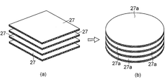
- FIGS. 5A and 5B are perspective explanatory views of a prepreg forming the laminated body of the example shown in FIG.
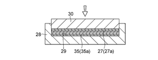
- FIG. 6 is a cross-sectional explanatory view of an example of a method for manufacturing the laminated body of the example shown in FIG. 1 using the prepreg shown in FIG.
- FIG. 7 is a perspective explanatory view of a laminate in the example shown in FIG. FIG.
- FIG. 8 is a partially enlarged cross-sectional explanatory view of the laminate in the example shown in FIG.
- FIG. 9 is an explanatory diagram of an example of the manufacturing method in another example of the embodiment of the present invention.
- FIG. 10 is an explanatory cross-sectional view of an example of the manufacturing method of another example shown in FIG.
- FIG. 11 is a partially enlarged cross-sectional explanatory view of the example shown in FIG. 12 (a) and 12 (b) are photographic explanatory views of the form of the sliding surface after the friction performance test of Example 1 of the present invention, where (a) is a plan photographic explanatory view, and (b) FIG. FIGS.
- FIG. 13A and 13B are photographic explanatory views of the form of the sliding surface after the friction performance test of Example 2 of the present invention, where FIG. FIG. 14 (a) and 14 (b) are photographic explanatory views of the form of the sliding surface after the friction performance test of the comparative example, wherein (a) is a plan photographic explanatory diagram and (b) is a side photographic description.
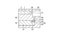
- FIG. FIG. 15 is a cross-sectional explanatory view of a preferred example of the sliding bearing according to the present invention.
- FIG. 16 is a partially enlarged cross-sectional explanatory view of the example shown in FIG.
- FIG. 17 is a longitudinal cross-sectional explanatory view of another preferred example of the sliding bearing according to the present invention.
- FIG. 18 is an explanatory plan view of a comparative example.
- a laminated sliding member 1 includes a base 4 having one flat surface 3 that is circular in plan view, and a sliding surface that is attached to the flat surface 3 of the base 4 and is circular in plan view. 2 and a solid lubricant layer 5 having 2.
- a substrate 4 comprising a laminate 6 having a flat surface 3 and a plurality of polyester fiber woven fabrics impregnated with a resol type phenolic resin containing a tetrafluoroethylene resin and being joined to each other,
- the flat surface 3 of the flat surface 3 is located at a desired distance W inward in the radial direction from the outer peripheral edge 7 and surrounded by a circle 9 as an imaginary line similar to the outer peripheral edge 7. It is an inner flat surface of the flat surface 3 other than the annular flat surface 8 which is an annular outer flat surface of the flat surface 3 which is located radially inward with respect to the annular flat surface 8 and surrounded by the circle 9.
- the flat surface 3 comprising the carrier surface 3a and the annular flat surface 8, the cylindrical wall surface 11 and the circular bottom wall surface 12 are provided with fuzzy fluffs 16 of a polyester fiber woven fabric, and the solid lubricant layer 5 comprises fuzzy 16 and
- the laminated body 6 extends to the concave portion 13 of the laminated body 6 and is attached to the flat surface 3 including the circular flat surface 3 a and the annular flat surface 8 of the laminated body 6.
- the distance (radial width) W is 0.5 to 1.1 times the diameter d of the opening surface 10 of the recess 13, and the plurality of recesses 13 are circular planes of the flat surface 3 of the laminate 6.
- 6 ⁇ n concave portions 13 are arranged on the n-th (n is a positive integer) virtual concentric circles P1, P2, and P3 from the center of the flat surface 3, which are arranged with O2 and O3.
- the resol-type phenolic resin impregnated in the polyester fiber woven fabric which is a reinforcing base material, is synthesized using phenols containing 50 to 100 mol% of bisphenol A and formaldehydes as amines as catalysts, and a gel of 500 to 1000 It has a number average molecular weight Mn measured by permeation chromatography (GPC) and a dispersity Mw / Mn which is a ratio of the weight average molecular weight Mw to the number average molecular weight Mn of 2.5 to 15.
- GPC permeation chromatography
- the proportion of bisphenol A (C 15 H 16 O 2 ) in phenols is 50 to 100 mol%. This is the ratio of the number of moles of bisphenol A to the total number of moles of all phenols added at the start of synthesis.
- the resol type phenol resin after synthesis has a number average molecular weight Mn measured by GPC measurement of 500 to 1000 and a dispersion degree Mw / Mn of a molecular weight distribution of 2.5 to 15. Affinity with the polyester fiber woven fabric as the base material is remarkably improved, and therefore, the polyester fiber woven fabric has good adhesion to the polyester fiber woven fabric without surface treatment.
- the laminate 6 formed using a fiber woven fabric has high rigidity and excellent mechanical strength, and also has extremely small swelling even when used in a humid atmosphere such as water.
- the number average molecular weight Mn by GPC measurement is preferably 500 to 1000, and the dispersity Mw / Mn is preferably 2.5 to 15.
- the number average molecular weight Mn is less than 500, the mechanical strength is lowered even if the affinity with the polyester fiber woven fabric is good, and when the number average molecular weight Mn exceeds 1000, the viscosity of the resol type phenol resin increases. It is too difficult to impregnate the polyester fiber woven fabric.
- phenols other than bisphenol A are included.
- examples of phenols other than bisphenol A include phenol, cresol, ethylphenol, aminophenol, resorcinol, xylenol, butylphenol, trimethylphenol, catechol, and phenylphenol.
- phenol is preferably used because of its characteristics.
- These phenols other than bisphenol A may be used alone, or two or more of them may be used as a mixture.
- formaldehydes examples include formalin, paraformaldehyde, salicylaldehyde, benzaldehyde, p-hydroxybenzaldehyde and the like.
- formalin and paraformaldehyde are preferably used because of their ease of synthesis.
- These formaldehydes may be used alone or in combination of two or more.
- amines used as a catalyst include triethylamine, triethanolamine, benzyldimethylamine, aqueous ammonia and the like. Among them, triethylamine and aqueous ammonia are preferably used from the viewpoint of ease of synthesis.
- the content of the resol type phenol resin contained in the laminate 6 is preferably 40 to 60% by mass.
- the content of the resol type phenol resin is less than 40% by mass, the moldability (production) to the laminated sliding member 1 is hindered, and when it exceeds 60% by mass, the mechanical strength of the laminate 6 is lowered.
- the tetrafluoroethylene resin (hereinafter abbreviated as “PTFE”) blended with the resol type phenol resin includes molding powder (hereinafter abbreviated as “high molecular weight PTFE”) for molding, and high molecular weight PTFE by radiation irradiation or the like. Any of PTFE having a lower molecular weight than that of (hereinafter abbreviated as “low molecular weight PTFE”) can be used.
- the molecular weight of high molecular weight PTFE is, for example, about 700,000 to 10 million or more, and the molecular weight of low molecular weight PTFE is, for example, about 10,000 to 500,000.
- Low molecular weight PTFE is mainly used as an additive material and is easy to grind and has good dispersibility.
- high molecular weight PTFE examples include “Teflon (registered trademark) 7-J”, “Teflon (registered trademark) 7A-J”, “Teflon (registered trademark) 70-J” manufactured by Mitsui DuPont Fluorochemical Co., Ltd.
- Examples include “Polyflon M-12 (trade name)” manufactured by Daikin Industries, Ltd., “Fluon G163 (trade name)”, “Fluon G190 (trade name)” manufactured by Asahi Glass Co., Ltd., and the like.
- low molecular weight PTFE examples include “TLP-10F (trade name)” manufactured by Mitsui DuPont Fluoro Chemical Co., Ltd., “Lublon L-5 (trade name)” manufactured by Daikin Industries, Ltd., and “Fullon” manufactured by Asahi Glass Co., Ltd. L150J (trade name) ”,“ Full-on L169J (trade name) ”,“ KTL-8N (trade name) ”,“ KTL-2N (trade name) ”, etc. manufactured by Kitamura.
- both high molecular weight PTFE and low molecular weight PTFE can be used, but when mixed with the resol type phenolic resin, in order to make it difficult to uniformly disperse and form voids, low molecular weight PTFE powder is preferred.
- the average particle size of the PTFE powder is 1 to 50 ⁇ m, preferably 1 to 30 ⁇ m, from the viewpoint of uniformly dispersing and preventing the formation of voids.
- the content of PTFE contained in the laminate 6 is suitably 10 to 30% by mass. If the PTFE content is less than 10% by mass, the effect of improving the friction and wear characteristics cannot be obtained, and if it exceeds 30% by mass, the viscosity of the resin may increase during molding and voids may be generated. In addition, there is a possibility that the adhesiveness of the resol type phenolic resin is lowered, the strength of the laminated sliding member 1 is lowered, or delamination is caused.
- the polyester fiber woven fabric is a woven fabric obtained by spinning polyester fibers according to a conventional method.
- the polyester fiber is generally obtained by polycondensation of a dicarboxylic acid component and a diol component.
- the dicarboxylic acid component include terephthalic acid, isophthalic acid, naphthalene-2,6-dicarboxylic acid and the like.
- the diol component include ethylene glycol, hydroquinone, bisphenol A, and biphenyl. Examples of compounds that serve as both components include p-hydroxybenzoic acid and 2-oxy-6-naphthoic acid.
- a typical polyester fiber is obtained from polyethylene terephthalate (PET) containing terephthalic acid and ethylene glycol as main components.
- PET polyethylene terephthalate
- General polyester fibers have low moisture absorption and water absorption and a moisture content of 0.4 to 0.5%. In contrast, cotton is usually 8-9%.
- the spinning form may be a filament yarn (filament yarn) obtained by twisting long fibers or a spun yarn (spun yarn) obtained by twisting short fibers.
- the woven fabric structure is not particularly limited, and includes plain weave, twill weave, satin weave mihara structure, change plain weave, change twill weave, change satin weave, etc., mixed structure of mihara texture and change tissue, etc. Can be used.
- the content of the polyester fiber woven fabric contained in the laminate 6 is preferably 25 to 35% by mass.
- the content of the polyester fiber woven fabric is less than 25% by mass, the reinforcing effect when the laminated sliding member 1 is obtained is not sufficient, and when it exceeds 35% by mass, the moldability (manufacturing) of the laminated sliding member 1 is hindered. It will be.
- the resol type phenolic resin contained in the laminate 6 is 40 to 60% by mass, the tetrafluoroethylene resin is 10 to 30% by mass, and the polyester fiber woven fabric is 25 to 35% by mass. Good strength and frictional wear characteristics can be obtained.
- the prepreg (resin-processed base material) of the laminate 6 can be manufactured using a manufacturing apparatus as shown in FIG. 4, for example. That is, in the present manufacturing apparatus shown in FIG. 4, the reinforcing base material 18 made of a polyester fiber woven fabric wound around the uncoiler 17 is made of PTFE powder and resol type phenolic resin varnish in which PTFE powder is uniformly dispersed by a feed roller 19.
- the mixed liquid 20 is sent to the container 21, and is passed through the mixed liquid 20 stored in the container 21 by the guide rollers 22 and 23 provided in the container 21.
- the reinforced base material 18 coated with the mixed liquid 20 and fed with the mixed liquid 20 is sent to the compression rolls 24 and 25 by the feed roller 19, and applied to the surface of the reinforcing base material 18 by the compression rolls 24 and 25.
- the mixed liquid 20 thus impregnated is impregnated into the fiber structure gap, and the solvent is applied to the reinforcing substrate 18 on which the mixed liquid 20 is impregnated and coated in a drying furnace 26.
- the reaction of the simultaneously resol type phenolic resin varnish blown is advanced, thereby formable prepreg laminate 6 (resin processing substrate) 27 is prepared.
- the solid content of a resol type phenol resin varnish prepared by dissolving a resol type phenol resin in a volatile solvent is about 30 to 65% by mass with respect to the entire resin varnish, and the viscosity of the resin varnish is About 800 to 5000 cP is preferable, and 1000 to 4000 cP is particularly preferable.
- such a prepreg 27 is cut into a square shape by the number of sheets to obtain a desired finished thickness, and then, as shown in FIG. A predetermined number of cut prepregs 27 are stacked and laminated in a rectangular recess 29, and then heated to a temperature of 140 to 160 ° C. in a mold 28, and a ram at a pressure of 4.9 to 7 MPa. 30 to produce a rectangular laminated molded article 31 in which the laminated prepregs 27 are joined and fused together as shown in FIG.
- the molded product 31 is machined to form a disk-shaped laminate 6 as shown in FIG.
- the disk-shaped laminate 6 formed in this way has high rigidity and excellent mechanical strength, and excellent friction and wear characteristics, and further swells even when used in a humid atmosphere such as oil or water. Since the amount is extremely small, it can be applied to a wide range of applications such as dry friction conditions, grease lubrication conditions, and water lubrication conditions.
- the disk-shaped laminate 6 is machined into a square prepreg 27 shown in FIG. 5 (a) to produce a disk-shaped prepreg 27a. 3.
- a predetermined number of disk-shaped prepregs 27a are stacked in a circular recess 29a of the mold 28 of the pressure device, and then heated to a temperature of 140 to 160 ° C. in the mold 28.
- a circular laminated body 6 as shown in FIG. 7B may be formed by pressure molding in the laminating direction with a ram 30 at a pressure of 9 to 7 MPa.
- a recess 13 is formed on the surface 15 to be the flat surface 3 of the disk-shaped laminate 6 by machining with an end mill or a drilling machine, and the cylindrical wall 11 defining the recess 13 is formed. Further, a thin fluff 16 of polyester fiber woven fabric is formed on the surface that becomes the circular bottom wall surface 12, and the surface 15 that becomes the flat surface 3 is roughened by polishing or sandblasting, and the surface 15 is made of polyester. A thin fluff 16 of fiber woven fabric is formed.
- the solid lubricant layer 5 that is adhered to the flat surface 3 of the laminated body 6 so as to coexist with the fluff 16 and extend to the recess 13 is composed of hydrocarbon wax, melamine cyanurate, PTFE, and phosphate. Is included.
- the hydrocarbon wax mainly imparts low friction to the solid lubricant layer 5, and as the hydrocarbon wax, a paraffin wax having approximately 24 or more carbon atoms, an olefin wax having approximately 26 or more carbon atoms,
- the hydrocarbon wax is selected from at least one of alkylbenzene having a carbon number of approximately 28 or more and microcrystalline wax.
- the wax of wax specifically, paraffin wax “150 (trade name)” manufactured by Nippon Seiwa Co., Ltd., Micro Crystalline wax “Hi-Mic-1080 (trade name)”, polyethylene wax “Licowax PE520 (trade name)” manufactured by Clariant Japan, and a mixture of polyethylene wax and paraffin wax made by Nikko Fine Products “Godes wax (trade name) ) "And the like.
- the blending ratio of the hydrocarbon wax is preferably 20 to 40% by mass. When the blending ratio is less than 20% by mass, the low friction property cannot be exhibited sufficiently, and when it exceeds 40% by mass, the bonding force between the solid lubricant layer 5 and the surface 15 is weakened.
- Melamine cyanurate is an addition compound of melamine and cyanuric acid or isocyanuric acid.
- a melamine molecule with a 6-membered ring structure and cyanuric acid (isocyanuric acid) molecules are arranged in a plane by hydrogen bonds, and the plane has a weak binding force. It is thought that it has a cleavage property like molybdenum disulfide or graphite.
- This melamine cyanurate plays a role of improving the wear resistance and load resistance of the solid lubricant layer 5 in particular.
- the melamine cyanurate is not particularly limited, and generally known melamine cyanurate can be used.
- JP-B-45-5595, JP-B-61-34430, JP-A-5-310716, JP-A-07-224049 and the like can be suitably used.
- Specific examples include “MCA-1 (trade name)” manufactured by Mitsubishi Chemical Corporation, “MC600”, “MC860”, “MC4000”, “MC6000” (all trade names) manufactured by Nissan Chemical Co., Ltd. .
- the blending ratio is preferably 15 to 30% by mass. If the blending ratio is less than 15% by mass, the desired effect of improving the wear resistance and load resistance cannot be obtained. If it exceeds 30% by mass, the wear resistance and load resistance are decreased.
- PTFE imparts low friction with the hydrocarbon wax, and as PTFE, both high molecular weight PTFE and low molecular weight PTFE similar to those described above can be used.
- the blending ratio of PTFE is preferably 20 to 50% by mass. When the blending ratio is less than 20% by mass, low friction is not sufficiently imparted to the solid lubricant layer 5, and when it exceeds 50% by mass, it is exposed on the sliding surface 2 of the solid lubricant layer 5. The ratio to be increased increases the wear resistance of the solid lubricant layer 5, and the shape retention is deteriorated, so that the strength of the solid lubricant layer 5 is decreased.
- Phosphate does not exhibit lubricity by itself, but plays a role in promoting the film forming property of the lubricant film of the solid lubricant layer 5 on the surface of the counterpart material in sliding between the solid lubricant layer 5 and the counterpart material.
- the phosphate include alkali metal or alkaline earth metal tertiary phosphate, secondary phosphate, pyrophosphate, phosphite, and metaphosphate. Specific examples include trilithium phosphate, dilithium hydrogen phosphate, lithium pyrophosphate, tricalcium phosphate, calcium monohydrogen phosphate, calcium pyrophosphate, lithium metaphosphate, magnesium metaphosphate, and calcium metaphosphate.
- the blending ratio of the phosphate is preferably 5 to 15% by mass.
- the blending ratio is less than 5% by mass, the effect of promoting the film forming property of the lubricating film on the surface of the counterpart material is not sufficiently exhibited.
- the mixing ratio exceeds 15% by mass, the lubricating film on the surface of the counterpart material is not achieved.
- the amount of transfer of the solid lubricant layer 5 becomes excessive, and the wear resistance of the solid lubricant layer 5 is decreased.
- the solid lubricant layer 5 comprising a lubricating composition containing 20 to 40% by weight of a hydrocarbon wax, 10 to 30% by weight of melamine cyanurate, 20 to 50% by weight of PTFE, and 5 to 15% by weight of a phosphate is a Henschel mixer, a super A predetermined amount of each component described above is mixed by a mixer such as a mixer, a ball mill, or a tumbler, and the resulting mixture is molded to produce a disk-shaped molded product. This molded product is used as the flat surface 3 of the laminate 6.
- the solid lubricant layer 5 which is placed on and compressed with the laminated body 6 to fill the concave portion 13 and mixed with the fine fluff 16 of the polyester fiber woven fabric is mixed with the flat surface 3 of the laminated body 6.
- the laminated sliding member 1 is formed.
- the laminated sliding member 1 having the base 4 provided with the other laminated bodies 32 bonded to each other may be used, and the laminated body 32 shown in FIG. 9 is manufactured by a manufacturing apparatus similar to the manufacturing apparatus shown in FIG. That is, the reinforcing base material 33 made of organic fiber or inorganic fiber woven fabric wound around the uncoiler 17 is sent to the container 21 storing the resol type phenolic resin varnish 34 by the feed roller 19, and the guide provided in the container 21.
- the resol-type phenol resin varnish 34 is applied to the surface of the reinforcing base material 33 by passing through the resol-type phenol resin varnish 34 stored in the container 21 by the rollers 22 and 23, and the resol-type phenol resin varnish 34.
- the reinforcing substrate 33 coated with is fed to the compression rolls 24 and 25 by the feed roller 19, and the resol-type phenol resin varnish 34 is impregnated into the fiber structure gap by the compression rolls 24 and 25, and the resol-type phenol Drying the reinforcing base material 33 impregnated with the resin varnish 34
- the reaction of the resole phenolic resin varnish 34 at the same time the solvent is blown off is advanced in the 26, this prepreg 35 of formable laminate 32 is produced by.
- inorganic fiber woven fabric such as glass fiber woven fabric, carbon fiber woven fabric, or aramid resin fiber woven fabric (copolyparaphenylene 3,4'oxydiphenylene terephthalamide).
- a resin fiber woven fabric for example, an organic fiber woven fabric such as “Technola (registered trademark)” manufactured by Teijin Techno Products Ltd. is used.
- a desired number of prepregs 35 or 35a cut into a square shape or a circular shape by machining are overlapped in a square shape or a circular recess 29 of a mold 28 of a heating and pressing apparatus.
- the prepreg 27 or 27a for the laminate 6 is placed on the upper surface thereof, and these are heated in the mold 28 to a temperature of 140 to 160 ° C., and are heated by the ram 30 at a pressure of 4.9 to 7 MPa.
- a multi-layer molded product having a square shape in plan view or a circular shape in plan view is produced by pressure molding in the laminating direction, and the prepreg 27 or 27a for the laminated body 6 and the laminated body 32 as shown in FIG.
- the prepreg 35 or 35a is joined to each other to produce a multilayer molded member 36 that is fused to each other.
- the multilayer molded member 36 thus produced includes a laminate 32 as a backing metal made of an inorganic fiber woven fabric or an organic fiber woven fabric, and the laminate 6 integrally joined to one surface 37 of the laminate 32. It has.
- the concave portion 13 and the fluff 16 are formed on the flat surface 3 of the laminate 6 in the same manner as described above to form the base body 4.
- the agent layer 5 is formed, and the laminated sliding member 1 as shown in FIG. 9 is produced.
- the other surface 41 of the stacked body 6 and the other surface 41a of the stacked body 32 are flat surfaces in a plan view.
- a disk-shaped prepreg 27a having a different diameter is formed in the same manner as described above.
- the base 4 may be formed by stacking and pressing a predetermined number of layers and pressing the laminate 6 having the other surface 41b that is circular in plan view and has a convex spherical shape as shown in FIG.
- Example 1 A spun yarn of cotton count 20 is used as warp and weft, the number of warp driven is 43 / inch, the number of weft driven is 42 / inch, and 30% by mass of polyester fiber woven fabric made of plain weave is used. A prepreg for a laminate comprising 23% by mass and the remaining resol type phenolic resin consisting of 47% by mass was used.
- This prepreg is cut into a square shape having a side length of 200 mm, and this is cut into a recess in the mold of the heating and pressing apparatus shown in FIG. 6 having a square shape recess having a side length of 200.5 mm.
- the 18 sheets were stacked and laminated, they were heated in the mold in the laminating direction at a temperature of 160 ° C. for 10 minutes and pressure-molded at a pressure of 7 MPa to obtain a rectangular laminated molded product.
- the obtained laminated molded product was machined to produce a laminated body with a diameter of 200 mm and a thickness of 8 mm in a plan view circular shape.
- a thin fluff of polyester fiber woven fabric as a reinforcing substrate is formed on the inner wall surface of the cylinder and the circular bottom wall surface that define the recesses formed by this end milling, and then one flat surface of the laminate in which these recesses are formed was subjected to polishing, and thin fluff of polyester fiber woven fabric was formed on the one flat surface.
- the virtual circle is an envelope of a cylindrical wall surface that defines 42 concave portions having a center on a concentric circle having the maximum diameter.
- hydrocarbon wax a mixture of polyethylene wax and paraffin wax made by Nikko Fine Products “Godes Wax (trade name)” 38% by mass, as PTFE, “KTL-2N (trade name)” 38% by weight made by Kitamura Co., Ltd.
- a mixture was prepared by charging 17% by mass of “MCA-1 (trade name)” manufactured by Mitsubishi Chemical Corporation as melamine cyanurate and 7% by mass of calcium pyrophosphate as a phosphate salt into a Henschel mixer. Thus, a disk-shaped sheet was produced.
- This disc-shaped sheet is formed on one flat surface of a laminated body having thin fluffs of polyester fiber woven fabric on a cylindrical inner wall surface and a circular bottom wall surface that define one flat surface and 169 recesses, respectively.
- a solid lubricant layer is formed on one flat surface of the laminated body by being placed on the surface, compression-molded and filled in the recesses, and mixed with the fine fuzz of the polyester fiber woven fabric to form a laminated sliding member. 1 was produced.
- Example 2 In the same manner as in Example 1, a laminated body having a diameter of 200 mm and a thickness of 8 mm and having a circular shape in plan view was produced.
- Comparative Example In the same manner as in Example 1, a laminate having a circular shape in plan view having a diameter of 200 mm and a thickness of 8 mm was produced.
- the width (distance W) of the annular flat surface of the moving surface is as small as 0.31 times the opening diameter of the recess, the solid lubricant layer on the outer periphery flows to the outside of the sliding surface, and cracks or chips on the outer periphery Defects, deformations, etc. are seen.
- the annular flat surface has a width (distance W) that is 0.5 to 1.06 times the opening diameter of the recess, so that high-speed sliding during an earthquake, for example, Even when subjected to high-speed sliding at 60 cm / sec, excellent friction performance is exhibited, and defects such as cracks and chipping and deformation do not occur on the sliding surface.
- the sliding bearing 39 incorporating the above-described laminated sliding member 1 includes a lower collar 52 having a circular recess 51 in a plan view that opens on one surface 40, and a lower collar 52.
- a rubber elastic body 54 having a circular shape in a plan view and having an annular notch step portion 53 on the outer peripheral edge of the upper surface, and an annular ring 55 fitted and fixed to the notch step portion 53.
- an intermediate plate 58 having a circular shape in plan view provided on the upper surface of the rubber elastic body 54 so as to be swingable and rotatable with respect to the lower collar 52 and having a circular recess 57 on the upper surface 56.
- the annular ring 55 is fitted on and fitted into the notch step portion 53 of the rubber elastic body 54, and is disposed on the upper surface of the protective ring 62 and the annular shape of the rubber elastic body 54.
- the metal compression ring 63 is inserted into and fitted into the notch step portion 53, and from the gap 64 between the outer peripheral surface of the intermediate plate 58 and the wall surface of the recess 51 of the lower collar 52.
- a sliding bearing 71 includes a lower collar 74 having a concave spherical surface 73 on one surface 72, a sliding surface 2 of the solid lubricant layer 5, and a convex spherical surface 41b.
- it comprises a laminated sliding member 1 that is slidably in contact with the concave spherical surface 73 at the surface 41b, and an upper collar 60 to which a sliding plate 59 that is slidably in contact with the sliding surface 2 of the laminated sliding member 1 is fixed. ing.
- a plurality of anchor bolts 81 which are embedded and fixed in the lower structure such as a bridge pier are fixed to the lower surfaces of the lower rods 52 and 74.
- a plurality of anchor bolts 82 embedded and fixed in an upper structure such as a bridge girder are also fixed to the upper rod 60.
Landscapes
- Engineering & Computer Science (AREA)
- Chemical & Material Sciences (AREA)
- Architecture (AREA)
- Mechanical Engineering (AREA)
- Oil, Petroleum & Natural Gas (AREA)
- Chemical Kinetics & Catalysis (AREA)
- General Chemical & Material Sciences (AREA)
- Organic Chemistry (AREA)
- Structural Engineering (AREA)
- Civil Engineering (AREA)
- Environmental & Geological Engineering (AREA)
- Business, Economics & Management (AREA)
- General Engineering & Computer Science (AREA)
- Emergency Management (AREA)
- Physics & Mathematics (AREA)
- Electromagnetism (AREA)
- Inorganic Chemistry (AREA)
- Sliding-Contact Bearings (AREA)
- Buildings Adapted To Withstand Abnormal External Influences (AREA)
- Vibration Prevention Devices (AREA)
- Lubricants (AREA)
- Laminated Bodies (AREA)
Abstract
積層すべり部材1は、平面視円形状の一方の平坦面3を有する基体4と、基体4の平坦面3に被着されていると共に平面視円形状の摺動面2を有した固体潤滑剤層5とを備えている。
Description
本発明は、積層すべり部材及び積層すべり部材を使用したすべり支承に関する。
従来、固体潤滑剤入りの積層すべり部材を得るにあたり、黒鉛や二硫化モリブデン又は四フッ化エチレン樹脂の粉末等の固体潤滑剤を分散含有させたフェノール樹脂ワニスに綿布基材を浸漬、引上げ、適宜加温して溶剤を逸散してこれら固体潤滑剤が綿布基材に付着含浸せしめられたプリプレグを得、これを積層成形する等の方法が用いられている。
ところで、綿布基材の浸漬、引上げによりプリプレグを形成するに際しての作業性を保つべく、固体潤滑剤の混入割合を比較的低くおさえると、摩擦係数が低下され得ず、また充分な耐摩耗性が得られない。
加えて、仮に固体潤滑剤の混入割合を高め得たとしても、単なる浸漬によっては綿布基材の繊維組織間隙にフェノール樹脂と固体潤滑剤との混合物が充分には充填されず、また混合物が基材に必ずしも充分には付着され得ず、このようなプリプレグを用いて積層成形すると、得られた積層すべり部材が層間剥離を起こす虞があり、その結果、積層すべり部材の機械的強度が著しく低下する虞がある。
このような問題を解決するべく、特許文献1には、補強基材に予め合成樹脂ワニスを含浸せしめ、ついでこのワニス含浸補強基材に固体潤滑剤入りワニスを塗布するか、固体潤滑剤の水分散体を塗布する等して該補強基材のほぼ表面にのみ固体潤滑剤を付着せしめるという方法が開示されているが、ここに開示された方法においても、積層すべり部材の低摩擦性、耐摩耗性等が必ずしも充分ではない。
特に近年において、このような積層すべり部材を、建築、土木分野における建物、橋梁又は高架道路等の建造物を支持する弾性支承装置と併用して設置したり、すべり支承として設置したりして、建物、橋梁、高架道路等の建造物に加わる地震力を減少させるすべり免震装置とした場合には、低摩擦性及び耐摩耗性の観点から使用に耐え難いという問題がある。
また、このようなすべり部材を、すべり免震装置に適用したものとして、不飽和ポリエステル樹脂に四フッ化エチエン樹脂を添加した樹脂組成物をポリエチレンテレフタレートの織布に含浸してなる免震装置が特許文献2において提案されている。
斯かるすべり部材は、従来のすべり部材ではなし得なかったすべり免震装置への適用を可能とするものであるが、すべり免震装置にあっては、摩擦係数の大小によって地震力によるすべり出しに大きく影響し、例えば摩擦係数が0.1程度の場合、地震力が0.1G(ガル)以上にならないとすべり出さず、特許文献2において提案されているすべり部材は、やはり低摩擦性の点で必ずしも満足のいくものではなく、免震装置の機能を阻害する虞がある。
すべり出し時の摩擦係数を低減させるには、免震装置の摺動面に固体潤滑剤等の潤滑被膜を形成する等の手段を採ることが考えられるが、地震時の高速摺動、例えば60cm/secの高速摺動を受けると摺動面は100℃の温度に達し、摺動面から潤滑被膜が溶融して流れ出し、摺動性をすこぶる悪化させる虞がある。
本発明は、上記実情に鑑みてなされたものであり、その目的とするところは、低摩擦性を有し、地震時に高速摺動を受けた場合においても、摺動摩擦熱の上昇による固体潤滑剤層の流出を阻止し得、また、摺動面に荷重が集中しても、摺動面での固体潤滑剤層の欠損や変形等を生じることない積層すべり部材及びこの積層すべり部材を使用したすべり支承を提供することにある。
本発明の積層すべり部材は、一方の平坦面に複数個の凹部を有する基体と、この基体の凹部まで延在して当該基体の少なくとも一方の平坦面に被着された固体潤滑剤層とを備えており、基体は、四フッ化エチレン樹脂を含有したレゾール型フェノール樹脂を含浸したポリエステル繊維織布を複数枚重ね合わせて互いに接合してなると共に前記一方の平坦面を具備した積層体を具備しており、複数個の凹部は、積層体の一方の平坦面の外周縁と当該外周縁から内方に所与の距離だけ離れて位置すると共に外周縁に相似形の仮想の線とで囲まれる当該積層体の一方の平坦面のうちの環状外側平坦面以外であって当該環状外側平坦面に対して内方に位置すると共に該仮想の線で囲まれる積層体の一方の平坦面のうちの内側平坦面で開口して積層体に配されており、複数の凹部の夫々は、積層体の円筒壁面と積層体の円形底壁面とで規定されており、内側平坦面及び環状外側平坦面からなる積層体の一方の平坦面、円筒壁面及び円形底壁面は、ポリエステル繊維織布の毛状の毛羽立ちを備えており、固体潤滑剤層は、これら毛羽立ちと混在一体となっていると共に積層体の凹部まで延在して積層体の少なくとも一方の平坦面に被着されている。
本発明の積層すべり部材によれば、固体潤滑剤層は、積層体の一方の平坦面、円筒壁面及び円形底壁面におけるポリエステル繊維織布の毛状の毛羽立ちと混在一体となって、積層体の一方の平坦面に被着されているため、摺動摩擦熱の上昇により固体潤滑剤層が溶融しても、その流出することを回避でき、しかも、複数の凹部の夫々は、積層体の環状外側平坦面以外の内側平坦面で開口しているため、当該環状外側平坦面に荷重が集中しても、外周縁近傍の環状外側平坦面での割れや欠け等の欠損や変形等の不具合を生じることはない。
本発明では、基体は、積層体の他方の面に一体的に接合されていると共に無機繊維織布又は有機繊維織布を複数枚重ね合わせて互いに接合した他の積層体を更に具備していてもよく、斯かる他の積層体を更に具備していると、他の積層体を裏金と機能させることができ、基体の更なる機械的強度を増大でき、外周縁近傍の円環状平坦面での割れや欠け等の欠損や変形等の不具合を更になくし得る。
本発明の積層すべり部材の好ましい例では、基体の一方の平坦面の外周縁から仮想の線までの外周縁に直交する直交方向(一方の平坦面が平面視円形状の場合には、その径方向、以下、同じ)の所与の距離は、凹部の開口径の0.5倍から1.1倍である。
斯かる距離が、凹部の開口径の0.5倍から1.1倍であることにより、基体の一方の平坦面の外周縁と仮想の線との間の基体の一方の平坦面のうちの環状外側平坦面への応力集中に起因する割れや欠け等の欠損や変形等の不具合をより効果的に回避することができることを実験により確認した。
所与の距離が凹部の開口径の0.5倍未満であると、環状外側平坦面の外周縁に直交する直交方向の幅が狭くなり、当該幅の狭い環状外側平坦面に荷重が作用すると、基体の一方の平坦面の外周縁に容易に割れや欠け等の欠損を生じる虞があり、また、斯かる距離が凹部の開口径の1.1倍を超えると、環状外側平坦面を被覆する固体潤滑剤層に対するアンカー効果が十分でなくなり、一方の平坦面に被着された固体潤滑剤層が流失する虞がある。
本発明の積層すべり部材において、複数個の凹部は、積層体の一方の平坦面の中心及び当該中心から外方にむけて互いに等間隔をもっていると共に外周縁に相似形の複数の仮想の同心環状線上に夫々中心をもって配されているとよく、斯かる場合、仮想の線は、最外側の同心線上に夫々中心をもって配された複数個の凹部を規定する円筒壁面に対する包絡線となっているとよい。
斯かる複数個の凹部は、すべり方向に固体潤滑剤層に対してアンカー効果を発揮するので、一方の平坦面を被覆した固体潤滑剤層の摺動摩擦熱の上昇に起因する流出を極力防ぐことができる。
本発明の積層すべり部材において、一方の平坦面の外周縁に直交する直交方向に関して隣接する二つの凹部の当該直交方向の間隔、複数の同心線における隣接同心線間の外周縁に直交する直交方向の各距離(隣接同心間幅)は、凹部の開口径の1.5から1.8倍であることが好ましい。
隣接同心線間の斯かる各距離が、凹部の開口径の1.5倍未満であると、一方の平坦面に配置される凹部の数が多くなり過ぎ、積層すべり部材の強度低下を惹き起こす虞があり、また、当該距離が凹部の開口径の1.8倍を超えると、固体潤滑剤層の当該凹部によるアンカー効果が十分でなくなり、固体潤滑剤層の流失を招く虞がある。
本発明の積層すべり部材において、一方の平坦面は、平面視円形状であって、複数の仮想の同心環状線は、複数の仮想の同心円からなり、これら複数の仮想の同心円のうちの一方の平坦面の中心からn番目(nは正の整数)の仮想の同心円上には、6×n個の凹部が当該n番目の仮想の同心円に関しての隣接凹部間で互いに等しい中心角をもって配されている。
基体の一方の平坦面が平面視円形状であって、複数の仮想の同心環状線が複数の仮想の円からなる場合において、凹部がこのように配されていると、一方の平坦面の中心から全ての径方向外方に向けて凹部が存在することになり、固体潤滑剤層に対する凹部によるすべてのすべり方向に対してのアンカー効果が発揮され、固体潤滑剤層の一方の面からの流失を極力防ぐことができる。
本発明においては、基体の一方の平坦面が上記のように平面視円形状であって、複数の仮想の同心環状線が同心円からなっていてもよいのであるが、基体の一方の平坦面は、平面視長方形、平面視正方形を含む平面視正多角形又は平面視円形の形状であればよく、基体の一方の平坦面が平面視長方形又は平面視正多角形の形状である場合には、当該一方の平坦面の中心は、これら形状の図形重心(平面図形重心)であり、外周縁に直交する直交方向は、各辺に直交する方向であり、仮想の線は、これら長方形又は正多角形に相似の長方形又は正多角形の線からなり、複数の仮想の同心環状線は、同一の位置に重心を有する一方、直交方向において斯かる重心からの距離が異なる複数の長方形又は正多角形の線からなり、基体の一方の平坦面が平面視円形の形状である場合には、当該一方の平坦面の中心は、この円の中心となり、外周縁に直交する直交方向は、円の径方向であり、仮想の線は、円からなり、外側平坦面は、円環であり、内側平坦面は、円形である。
本発明の積層すべり部材において、積層体は、好ましい例では、レゾール型フェノール樹脂を40~60質量%、四フッ化エチレン樹脂を10~30質量%及びポリエステル繊維織布を25~35重量%含んでいる。
本発明の積層すべり部材において、固体潤滑剤層は、炭化水素系ワックス、四フッ化エチレン樹脂、メラミンシアヌレート及び燐酸塩を含有していてもよく、この場合、好ましい例では、炭化水素系ワックス20~40質量%、四フッ化エチレン樹脂20~50質量%、メラミンシアヌレート15~30質量%及び燐酸塩5~15質量%を含有する。
本発明の積層すべり部材において、基体は、平坦な他方の面を有していても、これに代えて、凸球面状の他方の面を有していてもよく、斯かる他方の面は、平面視円形状であってよいが、基体の一方の平坦面と同様に、平面視長方形又は平面視正方形を含む平面視正多角形であってもよい。
本発明のすべり支承は、一方の平坦面で開口する凹部を備えた下沓と、この下沓の凹部に密に収納されると共に上面の外周縁に環状の切欠き段部を備えたゴム弾性体と、切欠き段部に嵌合固定された環状リングと、ゴム弾性体の上面に下沓に対して揺動回転自在となるように配置されると共に上面に凹部を備えた中間プレートと、中間プレートの凹部に嵌合固定された上記の積層すべり部材と、積層すべり部材の固体潤滑剤層に摺動自在に接触するすべり板を固定した上沓とを具備しており、斯かるすべり支承において、下沓の凹部、ゴム弾性体及び中間プレートは、積層すべり部材の平面視円形状と対応して、平面視円形状、平面視長方形又は平面視正方形を含む平面視正多角形の形状であってもよく、好ましい例では、平面視円形状であり、また、本発明のすべり支承においては、環状リングは、ゴム弾性体の環状の切欠き段部に嵌挿された合成樹脂製の保護リングと、この保護リングの上面に配されていると共にゴム弾性体の環状の切欠き段部に嵌挿された金属製の圧縮リングとを具備していてもよく、更にまた、本発明の他のすべり支承は、一方の面に凹球面を備えた下沓と、この下沓の凹球面に凸球面状の他方の面が接触するように下沓に配された上記の積層すべり部材と、この積層すべり部材の固体潤滑剤層に摺動自在に接触するすべり板を固定した上沓とを具備している。
本発明によれば、低摩擦性を有し、地震時に高速摺動を受けた場合においても、摺動摩擦熱の上昇により一方の平坦面からの固体潤滑剤層流出を阻止し得、また、摺動面に荷重が集中しても、摺動面での割れや欠け等の欠損や変形等の不具合を生じることのない積層すべり部材及びこの積層すべり部材を使用したすべり支承を提供することができる。
次に、本発明及びその実施の形態を、図に示す好ましい実施例に基づいて更に詳細に説明する。なお、本発明はこれらの実施例に何等限定されないのである。
図1から図3において、積層すべり部材1は、平面視円形状の一方の平坦面3を有する基体4と、基体4の平坦面3に被着されていると共に平面視円形状の摺動面2を有した固体潤滑剤層5とを備えている。
四フッ化エチレン樹脂を含有したレゾール型フェノール樹脂を含浸したポリエステル繊維織布を複数枚重ね合わせて互いに接合してなると共に平坦面3を具備した積層体6を具備した基体4は、積層体6の平坦面3の外周縁7と外周縁7から径方向の内方に所望の距離Wだけ離れて位置すると共に外周縁7に相似形の仮想の線としての円9とで囲まれる平坦面3のうちの環状外側平坦面である円環状平坦面8以外であって円環状平坦面8に対して径方向内方に位置すると共に円9で囲まれる平坦面3のうちの内側平坦面である円形平坦面3aで開口して積層体6に配されており、且つ円形平坦面3aでの平面視円形状の開口面10、積層体6の円筒壁面11及び積層体6の円形底壁面12で規定された複数個の凹部13を有しており、円形平坦面3a及び円環状平坦面8からなる平坦面3、円筒壁面11及び円形底壁面12は、ポリエステル繊維織布の毛状の毛羽立ち16を備えており、固体潤滑剤層5は、毛羽立ち16と混在一体となっていると共に積層体6の凹部13まで延在して積層体6の円形平坦面3a及び円環状平坦面8からなる平坦面3に被着されている。
距離(径方向の幅)Wは、凹部13の開口面10の径dの0.5倍から1.1倍であり、複数個の凹部13は、積層体6の平坦面3の円形の平面図形重心である中心O及び当該中心Oから径方向外方にむけて互いに等間隔Tをもった複数の仮想の同心環状線である複数の仮想の同心円P1、P2及びP3上に夫々中心O1、O2及びO3をもって配されており、平坦面3の中心からn番目(nは正の整数)の仮想の同心円P1、P2及びP3上の夫々には、6×n個の凹部13が、本例では同心円P1、P2及びP3上には、夫々6個、12個及び18個の凹部13が、同心円P1、P2及びP3の夫々に関しての隣接凹部13間で互いに等しい中心角θ1(=60°)、θ2(=30°)及びθ3(=20°)をもって配されており、等間隔Tは、開口面10の径dの1.5倍から1.8倍であり、仮想の円9は、同心円P3に中心O3をもって配された18個の凹部13を規定する円筒壁面11の包絡線となっている。
補強基材であるポリエステル繊維織布に含浸されたレゾール型フェノール樹脂は、ビスフェノールAを50~100モル%含むフェノール類とホルムアルデヒド類とをアミン類を触媒として合成されており、500~1000のゲルパーミエーションクロマトグラフィー(GPC)測定による数平均分子量Mnと、2.5~15の重量平均分子量Mwと数平均分子量Mnの比である分散度Mw/Mnとを有している。
レゾール型フェノール樹脂は、フェノール類のうち、ビスフェノールA(C15H16O2)の割合を50~100モル%とする。これは、合成開始時に投入する全フェノール類の合計モル数に対するビスフェノールAのモル数の比率である。
合成後のレゾール型フェノール樹脂は、500~1000のGPC測定による数平均分子量Mnと、2.5~15の分子量分布の分散度Mw/Mnを有しており、このレゾール型フェノール樹脂では、補強基材としてのポリエステル繊維織布との親和性が格段に向上しており、従って、ポリエステル繊維織布に表面処理を施すことなく、ポリエステル繊維織布との接着性が良好であり、斯かるポリエステル繊維織布を用いて形成された積層体6は、高い剛性を有すると共に機械的強度に優れている上に、水中等湿潤雰囲気での使用においても極めて小さい膨潤性を有している。
レゾール型フェノール樹脂において、ビスフェノールAが50モル%未満では、ポリエステル繊維織布との充分な親和性が得られず、ポリエステル繊維織布との充分な接着性を得ることができない。また、GPC測定による数平均分子量Mn500~1000であり、かつ分散度Mw/Mnが2.5~15であることが好ましい。数平均分子量Mnが500未満では、ポリエステル繊維織布との親和性が良好であっても機械的強度の低下をきたし、また数平均分子量Mnが1000を超えるとレゾール型フェノール樹脂の粘度が高くなりすぎてポリエステル繊維織布への含浸が困難となる。さらに分散度Mw/Mnが2.5未満ではポリエステル繊維織布との充分な接着力が得られず、また、分散度Mw/Mnが15を超えると、数平均分子量Mnが1000を超える場合と同様、ポリエステル繊維織布への含浸が困難となる。
フェノール類中のビスフェノールAが100モル%未満のときは、ビスフェノールA以外のフェノール類を含むことになる。ビスフェノールA以外のフェノール類としては、フェノール、クレゾール、エチルフェノール、アミノフェノール、レゾルシノール、キシレノール、ブチルフェノール、トリメチルフェノール、カテコール、フェニルフェノール等を挙げることができ、中でもフェノールがその特性から好ましく使用される。これらのビスフェノールA以外のフェノール類は、夫々単独で使用してもよく、また二種類以上を混合物として使用してもよい。
ホルムアルデヒド類としては、ホルマリン、パラホルムアルデヒド、サリチルアルデヒド、ベンズアルデヒド、p-ヒドロキシベンズアルデヒド等を挙げることができる。特に、合成の容易さからホルマリンやパラホルムアルデヒドが好ましく使用される。これらのホルムアルデヒド類は、夫々単独で使用してもよく、また二種類以上を混合物として使用してもよい。
触媒として用いるアミン類としては、トリエチルアミン、トリエタノールアミン、ベンジルジメチルアミン、アンモニア水等を挙げることができ、中でもトリエチルアミンやアンモニア水が合成の容易さから好ましく使用される。
積層体6中に含まれるレゾール型フェノール樹脂の含有量は、40~60質量%が好適である。レゾール型フェノール樹脂の含有量が40質量%未満では、積層すべり部材1への成形性(製造)に支障をきたし、また60質量%を超えると積層体6の機械的強度を低下させる。
レゾール型フェノール樹脂に配合される四フッ化エチレン樹脂(以下「PTFE」と略称する)としては、成形用のモールディングパウダー(以下「高分子量PTFE」と略称する)と、放射線照射等により高分子量PTFEに比べて分子量を低下させたPTFE(以下「低分子量PTFE」と略称する)のいずれも使用できる。高分子量PTFEの分子量は、例えば約70万~1000万又はそれ以上であり、低分子量PTFEの分子量は、例えば約1万~50万程度である。低分子量PTFEは、主に添加材料として使用され、粉砕し易く分散性がよい。
高分子量PTFEの具体例としては、三井デュポンフロロケミカル社製の「テフロン(登録商標)7-J」、「テフロン(登録商標)7A-J」、「テフロン(登録商標)70-J」等、ダイキン工業社製の「ポリフロンM-12(商品名)」等、旭硝子社製の「フルオンG163(商品名)」、「フルオンG190(商品名)」等が挙げられる。
低分子量PTFEの具体例としては、三井デュポンフロロケミカル社製の「TLP-10F(商品名)」等、ダイキン工業社製の「ルブロンL-5(商品名)」等、旭硝子社製の「フルオンL150J(商品名)」、「フルオンL169J(商品名)」等、喜多村社製の「KTL-8N(商品名)」、「KTL-2N(商品名)」等が挙げられる。
積層体6に対しては、高分子量PTFE及び低分子量PTFEのいずれも使用することができるが、レゾール型フェノール樹脂と混合するにあたって、均一に分散しボイドを生成し難くするためには、低分子量PTFEの粉末が好ましい。また、PTFE粉末の平均粒径は、均一に分散し、ボイドの生成を防ぐという観点から、1~50μm、好ましくは1~30μmである。
積層体6中に含まれるPTFEの含有量は、10~30質量%が適当である。PTFEの含有量が10質量%未満では、摩擦摩耗特性の向上に効果が得られず、また30質量%を超えると成形の際に樹脂の粘度が増大し、ボイドを生成する虞があることに加え、レゾール型フェノール樹脂の接着性を低下させ、積層すべり部材1としての強度低下を来たしたり、層間剥離を惹起させたりする虞がある。
ポリエステル繊維織布は、ポリエステル繊維を常法により紡糸し、織布としたものである。ポリエステル繊維は、一般にジカルボン酸成分とジオール成分の重縮合により得られる。ジカルボン酸成分としては、テレフタル酸、イソフタル酸、ナフタレン-2,6-ジカルボン酸等がある。ジオール成分としては、エチレングリコール、ハイドロキノン、ビスフェノールA、ビフェニル等がある。また、両成分を兼ねるものとしては、p-ヒドロキシ安息香酸、2-オキシ-6-ナフトエ酸等が挙げられる。代表的なポリエステル繊維として、テレフタル酸とエチレングリコールを主成分とするポリエチレンテレフタレート(PET)により得られる。一般的なポリエステル繊維は、吸湿性、吸水性が少なく水分率0.4~0.5%である。これに対し、綿は、通常8~9%である。
紡糸の形態は、長繊維を撚り合わせたフィラメント糸(フィラメント・ヤーン)であっても、短繊維を撚り合わせた紡績糸(スパン・ヤーン)であってもよい。また、織布の織物組織は特に限定されるものではなく、平織、綾織、朱子織の三原組織、変化平織、変化綾織、変化朱子織等の変化組織、三原組織と変化組織の混合組織等を用いることができる。
積層体6中に含まれるポリエステル繊維織布の含有量は、25~35質量%が好適である。ポリエステル繊維織布の含有量が25質量%未満では、積層すべり部材1としたときの補強効果が充分でなく、また35質量%を超えると積層すべり部材1の成形性(製造)に支障をきたすことになる。
積層体6中に含まれるレゾール型フェノール樹脂を40~60質量%、四フッ化エチレン樹脂を10~30質量%及びポリエステル繊維織布を25~35質量%とすることにより、成形性、機械的強度及び摩擦摩耗特性のいずれにおいても良好なものが得られる。
積層体6のプリプレグ(樹脂加工基材)は、例えば図4に示すような製造装置を用いて作製することができる。即ち、図4に示す本製造装置において、アンコイラ17に巻かれたポリエステル繊維織布からなる補強基材18は、送りローラ19によってPTFE粉末とPTFE粉末を均一に分散したレゾール型フェノール樹脂ワニスとの混合液20を貯えた容器21に送られ、容器21内に設けられた案内ローラ22及び23によって容器21内に貯えられた混合液20内を通過せしめられることにより、補強基材18の表面に混合液20が塗工され、混合液20が塗工された補強基材18は、送りローラ19によって圧縮ロール24及び25に送られ、圧縮ロール24及び25によって補強基材18の表面に塗工された混合液20が繊維組織隙間にまで含浸せしめられ、そして、混合液20が含浸塗工された補強基材18に対して乾燥炉26内で溶剤が飛ばされると同時にレゾール型フェノール樹脂ワニスの反応が進められ、これにより成形可能な積層体6のプリプレグ(樹脂加工基材)27が作製される。
本製造方法において、レゾール型フェノール樹脂を揮発性溶剤に溶かして調製されるレゾール型フェノール樹脂ワニスの固形分は、樹脂ワニス全体に対して約30~65質量%であり、樹脂ワニスの粘度は、約800~5000cPが好ましく、特に1000~4000cPが好ましい。
斯かるプリプレグ27は、図5(a)に示すように、所望の仕上がり厚さが得られる枚数だけ方形状に切断され、次いで、図6に示すように、加熱加圧装置の金型28の方形状の凹所29内に、切断された所定の枚数のプリプレグ27を重ね合わせて積層したのち、金型28内で140~160℃の温度に加熱し、4.9~7MPaの圧力でラム30により積層方向に加圧成形して図7(a)に示すような、積層されたプリプレグ27が互いに接合されて融着した状態となっている方形状の積層成形物31を作製し、積層成形物31に機械加工を施し、図7(b)に示すような円板状の積層体6を形成する。このように形成された円板状の積層体6は、剛性が高く機械的強度に優れていると共に摩擦摩耗特性に優れており、さらに、油中又は水中等の湿潤雰囲気での使用においても膨潤量が極めて小さいので、乾燥摩擦条件、グリース潤滑条件、さらには水潤滑条件等幅広い用途への適用が可能となる。円板状の積層体6は、図5(a)に示す方形状のプリプレグ27に、図5(b)に示すように、機械加工を施して円板状のプリプレグ27aを作製し、加熱加圧装置の金型28の円形状の凹所29a内に、円板状のプリプレグ27aを所定の枚数重ね合わせて積層したのち、金型28内で140~160℃の温度に加熱し、4.9~7MPaの圧力でラム30により積層方向に加圧成形して、図7(b)に示すような円形状の積層体6を形成してもよい。
次に、図8に示すように、円板状の積層体6の平坦面3となる表面15に、凹部13をエンドミル又はボール盤等による機械加工によって形成すると共に、凹部13を規定する円筒壁面11及び円形底壁面12となる面に、ポリエステル繊維織布の細い毛状の毛羽立ち16を形成すると共に、平坦面3となる表面15に研磨加工又はサンドブラストにより粗面化処理を施し、表面15にポリエステル繊維織布の細い毛状の毛羽立ち16を形成する。
積層体6の平坦面3に、毛羽立ち16と混在一体となって凹部13まで延在して被着されている固体潤滑剤層5は、炭化水素系ワックスとメラミンシアヌレートとPTFE及び燐酸塩とを包含している。
炭化水素系ワックスは、固体潤滑剤層5に、主として低摩擦性に付与し、炭化水素系ワックスとしては、炭素数がおおむね24以上のパラフィン系ワックス、炭素数がおおむね26以上のオレフィン系ワックス、炭素数がおおむね28以上のアルキルベンゼン及びマイクロクリスタリンワックスのうちの少なくとも一つから選択され、炭化水素系ワックスとして、具体的には、日本精蝋社製のパラフィンワックス「150(商品名)」、マイクロクリスタリンワックス「Hi-Mic-1080(商品名)」、クラリアントジャパン社製のポリエチレンワックス「リコワックスPE520(商品名)」、日興ファインプロダクツ社製のポリエチレンワックスとパラフィンワックスとの混合物「ゴデスワックス(商品名)」等が挙げられる。炭化水素系ワックスの配合割合は、好ましくは、20~40質量%である。配合割合が20質量%未満の場合は、低摩擦性を充分発揮し得ず、また40質量%を超えた場合は、固体潤滑剤層5と表面15との接合力を弱める結果となる。
メラミンシアヌレートは、メラミンとシアヌル酸またはイソシアヌル酸との付加化合物であり、6員環構造のメラミン分子とシアヌル酸(イソシアヌル酸)分子が水素結合により平面状に配列し、その平面が弱い結合力で層状に重なり合っており、二硫化モリブデンやグラファイトの様な劈開性を有すると考えられている。このメラミンシアヌレートは、特に固体潤滑剤層5の耐摩耗性及び耐荷重性を向上させる役割を果たす。メラミンシアヌレートとしては、特に限定されるものではなく、通常公知のメラミンシアヌレートを用いることができる。例えば、特公昭45-5595号公報、特公61-34430号公報、特開平5-310716号公報及び特開平07-224049号公報等に記載されたものを好適に使用することができる。具体的には、三菱化学社製の「MCA-1(商品名)や、日産化学社製の「MC600」、「MC860」、「MC4000」、「MC6000」(いずれも商品名)等が挙げられる。その配合割合は、好ましくは、15~30質量%である。配合割合が15質量%未満の場合は、所望の耐摩耗性、耐荷重性の向上効果が得られず、また30質量%を超えた場合は、却って耐摩耗性及び耐荷重性を低下させる。
PTFEは、炭化水素系ワックスと共に低摩擦性を付与するものでありPTFEとしては、前記と同様の高分子量PTFE及び低分子量PTFEのいずれも使用することができる。PTFEの配合割合は、好ましくは、20~50質量%である。配合割合が20質量%未満の場合は、固体潤滑剤層5への低摩擦性の付与が充分でなく、また50質量%を超えた場合は、固体潤滑剤層5の摺動面2に露出する割合が多くなり、固体潤滑剤層5の耐摩耗性を低下させると共に、保形性が悪化し、固体潤滑剤層5の強度が低下する。
燐酸塩は、それ自体では潤滑性を示さないが、固体潤滑剤層5と相手材との摺動において、相手材表面に固体潤滑剤層5の潤滑被膜の造膜性を助長する役割を果たす。燐酸塩としては、アルカリ金属またはアルカリ土類金属の第三燐酸塩、第二燐酸塩、ピロ燐酸塩、亜燐酸塩、メタ燐酸塩等が挙げられる。具体的には、燐酸三リチウム、燐酸水素二リチウム、ピロ燐酸リチウム、燐酸三カルシウム、燐酸一水素カルシウム、ピロ燐酸カルシウム、メタ燐酸リチウム、メタ燐酸マグネシウム、メタ燐酸カルシウム等が挙げられる。燐酸塩の配合割合は、好ましくは、5~15質量%である。配合割合が5質量%未満の場合は、相手材表面への潤滑被膜の造膜性を助長するという効果が充分発揮されず、また15質量%を超えた場合は、相手材表面への潤滑被膜の移着量が過多になって、却って固体潤滑剤層5の耐摩耗性を低下させる。
炭化水素系ワックス20~40質量%、メラミンシアヌレート10~30質量%、PTFE20~50質量%及び燐酸塩5~15質量%を含む潤滑組成物からなる固体潤滑剤層5は、ヘンシェルミキサー、スーパーミキサー、ボールミル、タンブラー等の混合機によって上述の各成分の所定量を混合し、得られた混合物を成形して円板状の成形物を作製し、この成形物を積層体6の平坦面3に載置し、積層体6と共に圧縮成形して、凹部13に充填すると共にポリエステル繊維織布の細い毛状の毛羽立ち16と混在一体となった固体潤滑剤層5を積層体6の平坦面3に形成し、これにより、積層すべり部材1を形成する。
ところで、図9に示すように、積層体6に加えて、積層体6の円形状の他方の面41に一体的に接合されていると共に無機繊維織布又は有機繊維織布を複数枚重ね合わせて互いに接合した他の積層体32を具備した基体4をもった積層すべり部材1でもよく、図9に示す積層体32は、図6に示す製造装置と同様の製造装置によって製作される。すなわち、アンコイラ17に巻かれた有機繊維又は無機繊維織布からなる補強基材33は、送りローラ19によってレゾール型フェノール樹脂ワニス34を貯えた容器21に送られ、容器21内に設けられた案内ローラ22及び23によって容器21内に貯えられたレゾール型フェノール樹脂ワニス34内を通過せしめられることにより、補強基材33の表面にレゾール型フェノール樹脂ワニス34が塗工され、レゾール型フェノール樹脂ワニス34が塗工された補強基材33は送りローラ19によって圧縮ロール24及び25に送られ、圧縮ロール24及び25によってレゾール型フェノール樹脂ワニス34が繊維組織隙間にまで含浸せしめられ、そして、レゾール型フェノール樹脂ワニス34が含浸塗工された補強基材33に対して乾燥炉26内で溶剤が飛ばされると同時にレゾール型フェノール樹脂ワニス34の反応が進められ、これにより成形可能な積層体32のプリプレグ35が作製される。
積層体32に使用される補強繊維織布としては、ガラス繊維織布、炭素繊維織布等の無機繊維織布又はアラミド樹脂繊維織布(コポリパラフェニレン・3,4’オキシジフェニレン・テレフタルアミド樹脂繊維織布、例えば帝人テクノプロダクツ社製の「テクノーラ(登録商標)」)等の有機繊維織布が使用される。
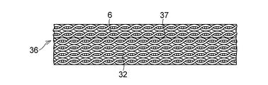
機械加工により方形状又は円形状に切断したプリプレグ35又は35aを、図10に示すように、加熱加圧装置の金型28の方形状又は円形状の凹所29内に、所望の枚数重ね合わせて積層したのち、その上面に積層体6用のプリプレグ27又は27aを載置し、これらを金型28内において140~160℃の温度に加熱し、4.9~7MPaの圧力でラム30により積層方向に加圧成形して平面視方形状又は平面視円形状の複層成形物を作製し、図11に示すような、積層された積層体6用のプリプレグ27又は27aと積層体32用のプリプレグ35又は35aとが互いに接合されて、互いに融着した状態となっている複層成形部材36を作製する。このように作製された複層成形部材36は、無機繊維織布又は有機繊維織布からなる裏金としての積層体32と積層体32の一方の面37に一体に接合された積層体6とを具備している。
斯かる積層体32及び6を具備した複層成形部材36において、積層体6の平坦面3に、前記と同様に、凹部13及び毛羽立ち16を形成して基体4とし、この基体4に固体潤滑剤層5を形成して、図9に示すような積層すべり部材1を作製する。
上記の例では、積層体6の他方の面41及び積層体32の他方の面41aを平面視円形状の平坦面としたが、例えば径の異なる円板状のプリプレグ27aを前記と同様にして所定の枚数重ね合わせて積層、加圧して、図2に示すように平面視円形状であって凸球面状の他方の面41bを有した積層体6をもって基体4を形成してもよい。
実施例1
縦糸及び横糸として綿番手20の紡績糸を使用し、縦糸の打ち込み本数を43本/インチ、横糸の打ち込み本数を42本/インチとして平織にて作製したポリエステル繊維織布が30質量%、PTFEが23質量%、残部のレゾール型フェノール樹脂が47質量%からなる積層体用のプリプレグを使用した。
縦糸及び横糸として綿番手20の紡績糸を使用し、縦糸の打ち込み本数を43本/インチ、横糸の打ち込み本数を42本/インチとして平織にて作製したポリエステル繊維織布が30質量%、PTFEが23質量%、残部のレゾール型フェノール樹脂が47質量%からなる積層体用のプリプレグを使用した。
このプリプレグを一辺の長さが200mmの方形状に切断し、これを一辺の長さが200.5mmの方形状の凹所を有する図6に示した加熱加圧装置の金型の凹所内に18枚重ね合わせて積層したのち、金型内で積層方向に160℃の温度で10分間加熱し、圧力7MPaで加圧成形して方形状の積層成形物を得た。得られた積層成形物に機械加工を施し、直径200mm、厚さ8mmの平面視円形状の積層体を作製した。
積層体の一方の平坦面に、外周縁から径方向の内方に8.5mm(凹部の開口部の直径の1.06倍)距離Wをもって離れた仮想の円内に12.5mmの等間隔の同心円上にそれぞれ6個、12個、18個、24個、30個、36個及び42個並びに中心Oの1個を含んで合計169個の深さ0.9mmの凹部をエンドミル加工により形成した。このエンドミル加工により形成した凹部を規定する円筒内壁面及び円形底壁面に補強基材のポリエステル繊維織布の細い毛状の毛羽立ちを形成し、ついで、これら凹部を形成した積層体の一方の平坦面に研磨加工を施し、当該一方の平坦面にポリエステル繊維織布の細い毛状の毛羽立ちを形成した。仮想の円は、最大の径をもった同心円上に中心を有する42個の凹部を規定する円筒壁面の包絡線となっている。
炭化水素系ワックスとして、日興ファインプロダクツ社製のポリエチレンワックスとパラフィンワックスとの混合物「ゴデスワックス(商品名)」38質量%、PTFEとして、喜多村社製の「KTL-2N(商品名)」38質量%、メラミンシアヌレートとして、三菱化学社製の「MCA-1(商品名)」17質量%、燐酸塩として、ピロリン酸カルシウム7質量%をヘンシェルミキサーに投入して混合物を作製し、この混合物を使用して円板状のシートを作製した。
この円板状のシートを、一方の平坦面と169個の凹部の夫々を規定する円筒内壁面及び円形底壁面とにポリエステル繊維織布の細い毛状の毛羽立ちを備えた積層体の一方の平坦面に載置し、圧縮成形して凹部に充填させると共にポリエステル繊維織布の細い毛状の毛羽立ちと混在一体化させて固体潤滑剤層を積層体の一方の平坦面に形成し、積層すべり部材1を作製した。
実施例2
実施例1と同様にして直径200mm、厚さ8mmの平面視円形状の積層体を作製した。
実施例1と同様にして直径200mm、厚さ8mmの平面視円形状の積層体を作製した。
平面視円形状の積層体の一方の平坦面に、外周縁から径方向の内方に4.5mm(凹部の開口部の直径の0.5倍)の距離Wをもって位置した仮想の円内に等間隔に13.8mmの同心状であって13.8mmの等間隔に位置した仮想の同心円上の夫々に6個、12個、18個、24個、30個、36個及び42個並びに中心の1個を含んで合計169個の深さ0.9mmの凹部をエンドミル加工により実施例1と同様にして形成した。以下、合計169個の凹部を有した積層体の一方の平坦面に、実施例1と同様にして、固体潤滑剤層を形成し、積層すべり部材1を作製した。
比較例
実施例1と同様にして直径200mm、厚さ8mmの平面視円形状の積層体を作製した。
実施例1と同様にして直径200mm、厚さ8mmの平面視円形状の積層体を作製した。
斯かる積層体の一方の平坦面に、外周縁から径方向の内方に2.5mm(凹部の開口部の直径の0.31倍)の距離Wをもって離れた仮想の円内に14.0mmの等間隔の同心円上のそれぞれに6個、12個、18個、24個、30個、36個及び42個並びに中心Oの1個を含んで合計169個の深さ0.9mmの凹部をエンドミル加工により実施例1と同様にして形成した。以下、合計169個の凹部を有した積層体の一方の平坦面に、実施例1と同様にして、固体潤滑剤層を形成し、図18に示す積層すべり部材1を作製した。
次に、実施例1及び実施例2と比較例とからなる積層すべり部材について、下記に示す試験条件にて摩擦性能を試験した。
<試験条件>
面圧 20MPa、40MPa、60MPa
加振速度 1cm/sec、5cm/sec、10cm/sec、20cm/sec、30cm/sec、60cm/sec
相手材 ステンレス鋼板(SUS316)
試験方法 二軸試験機の台上に固定された相手材の表面に積層すべり部材の固体潤滑剤層を摺動自在に接触させると共に、積層すべり部材に面圧が20MPa、40MPa、60MPaとなるように荷重を加え、相手材側を振幅±200mmの正弦波で11回(11サイクル)加振した。
面圧 20MPa、40MPa、60MPa
加振速度 1cm/sec、5cm/sec、10cm/sec、20cm/sec、30cm/sec、60cm/sec
相手材 ステンレス鋼板(SUS316)
試験方法 二軸試験機の台上に固定された相手材の表面に積層すべり部材の固体潤滑剤層を摺動自在に接触させると共に、積層すべり部材に面圧が20MPa、40MPa、60MPaとなるように荷重を加え、相手材側を振幅±200mmの正弦波で11回(11サイクル)加振した。
試験結果を表1から表3に示す。


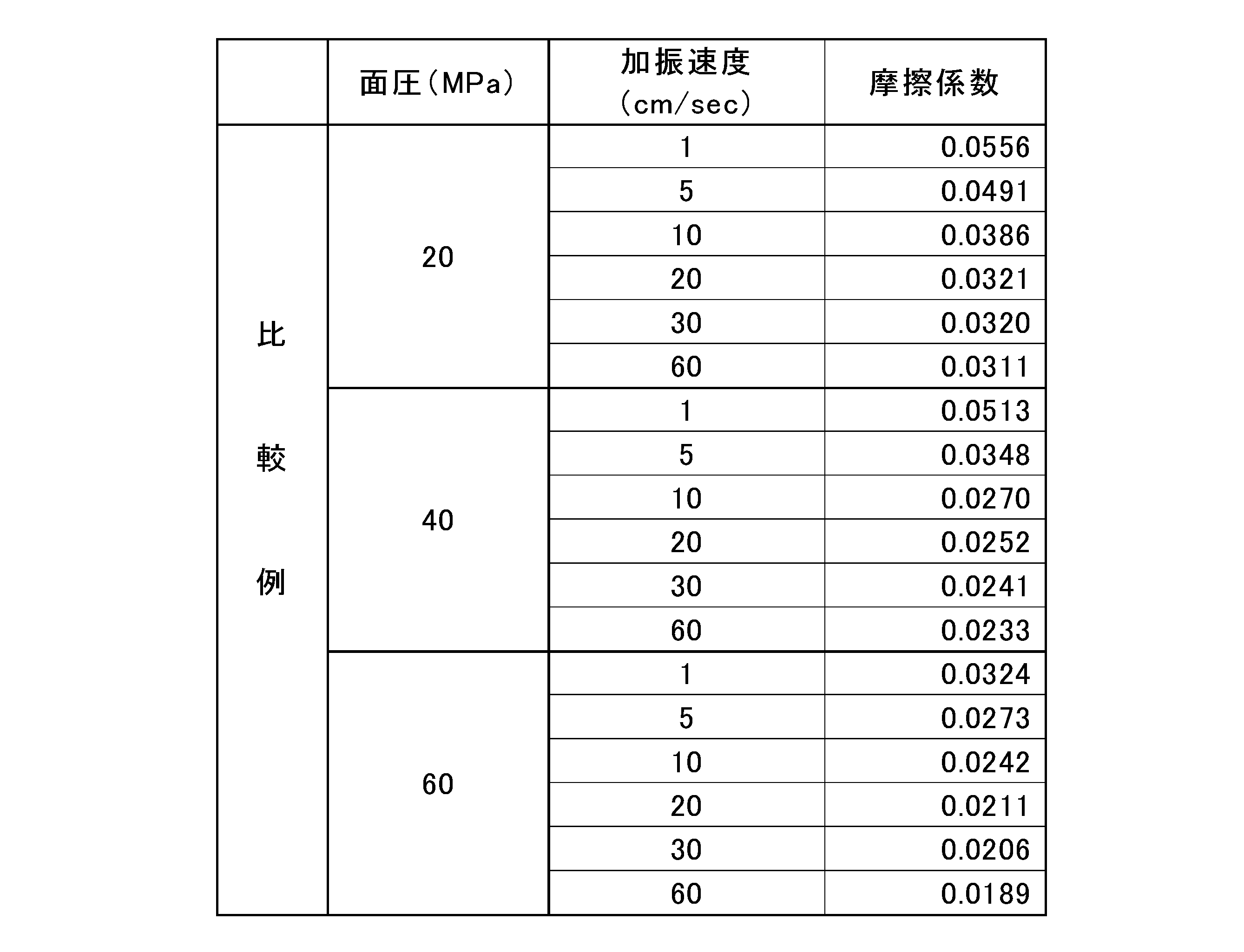
以上の試験結果から、実施例1及び実施例2と比較例とからなる積層すべり部材の間には、摩擦性能に大きな差は認められなかったが、試験後の積層すべり部材の摺動面の形態に大きな差が認められた。すなわち、実施例1の積層すべり部材の試験後の摺動面の形態を示す図12(a)及び(b)、実施例2の積層すべり部材の上記試験後の摺動面の形態を示す図13(a)及び(b)及び比較例の積層すべり部材の試験後の摺動面の形態を示す図14(a)及び(b)を比較すると分かるように、比較例の積層すべり部材の摺動面の円環状平坦面の幅(距離W)が凹部の開口径の0.31倍と小さいため、外周縁での固体潤滑剤層が摺動面外に流動し、外周縁に割れや欠け等の欠損や変形等が見られる。
実施例1及び2の積層すべり部材においては、円環状平坦面は、凹部の開口径の0.5倍ないし1.06倍の幅(距離W)をもっているので、地震時の高速摺動、例えば60cm/secの高速摺動を受けた場合においても、優れた摩擦性能を発揮すると共に、摺動面に割れや欠け等の欠損や変形等の不具合を生じることがない。
図15及び図16に示すように、以上の積層すべり部材1を組み込んだすべり支承39は、一方の面40で開口する平面視円形状の凹部51を備えた下沓52と、下沓52の凹部51に密に収納されると共に、上面の外周縁に環状の切欠き段部53を備えた平面視円形状のゴム弾性体54と、切欠き段部53に嵌合固定された環状リング55と、ゴム弾性体54の上面に下沓52に対して揺動回転自在となるように配置されると共に上面56に円形の凹部57を備えた平面視円形状の中間プレート58と、中間プレート58の凹部57に嵌合固定された積層すべり部材1と、積層すべり部材1の固体潤滑剤層5の摺動面2に摺動自在に接触するすべり板59を固定した上沓60とを具備している。
環状リング55は、ゴム弾性体54の切欠き段部53に嵌挿、嵌合された合成樹脂製の保護リング62と、保護リング62の上面に配されていると共にゴム弾性体54の環状の切欠き段部53に嵌挿、嵌合された金属製の圧縮リング63とを具備しており、中間プレート58の外周面と下沓52の凹部51での壁面との間の隙間64からのゴム弾性体54の外周縁部のはみ出しを防止して、ゴム弾性体54の損傷を防止するようになっている。
図17に示す他の態様のすべり支承71は、一方の面72に凹球面73を備えた下沓74と、固体潤滑剤層5の摺動面2及び凸球面状の面41bを備えている一方、面41bで凹球面73に摺動自在に接触した積層すべり部材1と、積層すべり部材1の摺動面2に摺動自在に接触したすべり板59を固定した上沓60とを具備している。
図15、図16及び図17に示したすべり支承39及び71において、下沓52及び74の夫々の下面には、橋脚等の下部構造に埋設固定される複数個のアンカーボルト81が固定されており、上沓60にも、橋桁等の上部構造に埋設固定される複数個のアンカーボルト82が固定されている。
すべり支承39及び71においては、積層すべり部材1が用いられているので、地震時に、例えば60cm/secの高速摺動を受けた場合においても、優れた摩擦性能を発揮する。
1 積層すべり部材
2 摺動面
3、3a 平坦面
4 基体
5 固体潤滑剤層
6、32 積層体
7 外周縁
8 円環状平坦面
13 凹部
16 毛羽立ち
39、71 すべり支承
2 摺動面
3、3a 平坦面
4 基体
5 固体潤滑剤層
6、32 積層体
7 外周縁
8 円環状平坦面
13 凹部
16 毛羽立ち
39、71 すべり支承
Claims (17)
- 一方の平坦面に複数個の凹部を有する基体と、この基体の凹部まで延在して当該基体の少なくとも一方の平坦面に被着された固体潤滑剤層とを備えており、基体は、四フッ化エチレン樹脂を含有したレゾール型フェノール樹脂を含浸したポリエステル繊維織布を複数枚重ね合わせて互いに接合してなると共に前記一方の平坦面を具備した積層体を具備しており、複数個の凹部は、積層体の一方の平坦面の外周縁と当該外周縁から内方に所与の距離だけ離れて位置すると共に外周縁に相似形の仮想の線とで囲まれる当該積層体の一方の平坦面のうちの環状外側平坦面以外であって当該環状外側平坦面に対して内方に位置すると共に該仮想の線で囲まれる積層体の一方の平坦面のうちの内側平坦面で開口して積層体に配されており、複数の凹部の夫々は、積層体の円筒壁面と積層体の円形底壁面とで規定されており、内側平坦面及び環状外側平坦面からなる積層体の一方の平坦面、円筒壁面及び円形底壁面は、ポリエステル繊維織布の毛状の毛羽立ちを備えており、固体潤滑剤層は、これら毛羽立ちと混在一体となっていると共に積層体の凹部まで延在して積層体の少なくとも一方の平坦面に被着されている積層すべり部材。
- 基体は、積層体の他方の面に一体的に接合されていると共に無機繊維織布又は有機繊維織布を複数枚重ね合わせて互いに接合した他の積層体を更に具備している請求項1に記載の積層すべり部材。
- 基体の一方の平坦面の外周縁から仮想の線までの所与の距離は、凹部の開口径の0.5倍から1.1倍である請求項1又は2に記載の積層すべり部材。
- 複数個の凹部は、積層体の一方の平坦面の中心及び当該中心から外方にむけて互いに等間隔をもっていると共に外周縁に相似形の複数の仮想の同心環状線上に夫々中心をもって配されている請求項1から3のいずれか一項に記載の積層すべり部材。
- 基体の一方の平坦面は、平面視円形状であり、複数の仮想の同心環状線は、複数の仮想の同心円からなり、これら複数の仮想の同心円のうちの一方の平坦面の中心からn番目(nは正の整数)の仮想の同心円上には、6×n個の凹部が当該n番目の仮想の同心円に関しての隣接凹部間で互いに等しい中心角をもって配されている請求項4に記載の積層すべり部材。
- 一方の平坦面は、平面視円形状であって、仮想の線は、円からなり、外側平坦面は、円環状であり、内側平坦面は、円形である請求項1から5のいずれか一項に記載の積層すべり部材。
- 積層体は、レゾール型フェノール樹脂を40~60質量%、四フッ化エチレン樹脂を10~30質量%及びポリエステル繊維織布を25~35重量%含む請求項1から6のいずれか一項に記載の積層すべり部材。
- 固体潤滑剤層は、炭化水素系ワックス、四フッ化エチレン樹脂、メラミンシアヌレート及び燐酸塩を含有する請求項1から7のいずれか一項に記載の積層すべり部材。
- 固体潤滑剤層は、炭化水素系ワックス20~40質量%、四フッ化エチレン樹脂20~50質量%、メラミンシアヌレート15~30質量%及び燐酸塩5~15質量%を含有する請求項8に記載の積層すべり部材。
- 基体は、平坦な他方の面を有する請求項1から9のいずれか一項に記載の積層すべり部材。
- 他方の面は、平面視円形状である請求項10に記載のすべり部材。
- 基体は、凸球面状の他方の面を有する請求項1から9のいずれか一項に記載のすべり部材。
- 他方の面は、平面視円形状である請求項12に記載のすべり部材。
- 一方の面で開口する凹部を備えた下沓と、この下沓の凹部に密に収納されると共に上面の外周縁に環状の切欠き段部を備えたゴム弾性体と、切欠き段部に嵌合固定された環状リングと、ゴム弾性体の上面に下沓に対して揺動回転自在となるように配置されると共に上面に凹部を備えた中間プレートと、中間プレートの凹部に嵌合固定された請求項10又は11に記載の積層すべり部材と、積層すべり部材の固体潤滑剤層に摺動自在に接触するすべり板を固定した上沓とを具備したすべり支承。
- 下沓の凹部、ゴム弾性体及び中間プレートは、平面視円形状である請求項14に記載のすべり支承。
- 環状リングは、ゴム弾性体の環状の切欠き段部に嵌合された合成樹脂製の保護リングと、この保護リングの上面に配されていると共にゴム弾性体の環状の切欠き段部に嵌合された金属製の圧縮リングとを具備している請求項14又は15に記載のすべり支承。
- 一方の面に凹球面を備えた下沓と、この下沓の凹球面に凸球面状の他方の面が接触するようにして下沓に配された請求項12又は13に記載の積層すべり部材と、この積層すべり部材の固体潤滑剤層に摺動自在に接触するすべり板を固定した上沓とを具備しているすべり支承。
Priority Applications (3)
| Application Number | Priority Date | Filing Date | Title |
|---|---|---|---|
| EP14822878.6A EP3021002B1 (en) | 2013-07-11 | 2014-06-23 | Laminate sliding member, and sliding bearing using said laminate sliding member |
| CN201480039248.7A CN105378329A (zh) | 2013-07-11 | 2014-06-23 | 层叠滑动部件及使用该层叠滑动部件的滑动支承 |
| US14/903,927 US9732538B2 (en) | 2013-07-11 | 2014-06-23 | Laminated sliding member and sliding bearing using the laminated sliding member |
Applications Claiming Priority (2)
| Application Number | Priority Date | Filing Date | Title |
|---|---|---|---|
| JP2013145923A JP6143588B2 (ja) | 2013-07-11 | 2013-07-11 | 積層すべり部材及びこの積層すべり部材を使用したすべり支承 |
| JP2013-145923 | 2013-07-11 |
Publications (1)
| Publication Number | Publication Date |
|---|---|
| WO2015004865A1 true WO2015004865A1 (ja) | 2015-01-15 |
Family
ID=52279575
Family Applications (1)
| Application Number | Title | Priority Date | Filing Date |
|---|---|---|---|
| PCT/JP2014/003346 Ceased WO2015004865A1 (ja) | 2013-07-11 | 2014-06-23 | 積層すべり部材及びこの積層すべり部材を使用したすべり支承 |
Country Status (6)
| Country | Link |
|---|---|
| US (1) | US9732538B2 (ja) |
| EP (1) | EP3021002B1 (ja) |
| JP (1) | JP6143588B2 (ja) |
| CN (1) | CN105378329A (ja) |
| TW (1) | TWI628340B (ja) |
| WO (1) | WO2015004865A1 (ja) |
Families Citing this family (7)
| Publication number | Priority date | Publication date | Assignee | Title |
|---|---|---|---|---|
| DE102015115385B4 (de) * | 2015-09-11 | 2019-08-01 | Miba Industrial Bearings Germany Gmbh | Kippsegment und Kippsegmentgleitlager |
| FR3061750B1 (fr) * | 2017-01-10 | 2019-08-23 | Renault S.A.S | Butee fixe d'un systeme de butees fixe et tournante destine a supporter une charge axiale. |
| CN106759929A (zh) * | 2017-03-10 | 2017-05-31 | 清华大学 | 摩擦滑移支座 |
| WO2018231845A2 (en) * | 2017-06-13 | 2018-12-20 | Ggb, Inc. | Solid lubricant compositions and bearings incorporating the same |
| JP6902972B2 (ja) * | 2017-09-14 | 2021-07-14 | オイレス工業株式会社 | 免震装置 |
| GB2569158B (en) * | 2017-12-07 | 2020-08-05 | Mahle Engine Systems Uk Ltd | Bearing material, bearing element and method |
| JP7092607B2 (ja) * | 2018-08-09 | 2022-06-28 | オイレス工業株式会社 | すべり支承 |
Citations (10)
| Publication number | Priority date | Publication date | Assignee | Title |
|---|---|---|---|---|
| JPS6134430B2 (ja) | 1977-10-04 | 1986-08-07 | Asahi Chemical Ind | |
| JPH05310716A (ja) | 1992-05-08 | 1993-11-22 | Nissan Chem Ind Ltd | メラミンシアヌレートの製造方法 |
| JPH07224049A (ja) | 1994-02-08 | 1995-08-22 | Nissan Chem Ind Ltd | 表面処理されたメラミンシアヌレート粉末およびその製造方法 |
| JPH11182095A (ja) | 1997-12-17 | 1999-07-06 | Ntn Corp | 免震装置 |
| JP2004190804A (ja) * | 2002-12-12 | 2004-07-08 | Oiles Ind Co Ltd | すべり部材及び該すべり部材の製造方法並びに該すべり部材を使用したすべり免震装置 |
| JP2004339259A (ja) * | 2003-05-13 | 2004-12-02 | Oiles Ind Co Ltd | 固体潤滑剤および摺動部材 |
| JP2008045722A (ja) * | 2006-08-21 | 2008-02-28 | Oiles Ind Co Ltd | 免震装置 |
| JP2008190674A (ja) * | 2007-02-07 | 2008-08-21 | Oiles Ind Co Ltd | 円筒状すべり軸受及びこの円筒状すべり軸受を使用した軸受装置 |
| JP2009091447A (ja) * | 2007-10-09 | 2009-04-30 | Oiles Ind Co Ltd | 摺動部材用繊維強化樹脂組成物及び積層摺動部材 |
| JP2012036606A (ja) * | 2010-08-05 | 2012-02-23 | Nippon Pillar Packing Co Ltd | 支承装置 |
Family Cites Families (10)
| Publication number | Priority date | Publication date | Assignee | Title |
|---|---|---|---|---|
| US3151015A (en) | 1961-01-30 | 1964-09-29 | American Brake Shoe Co | Bearings |
| JPH10280320A (ja) * | 1997-04-10 | 1998-10-20 | Yokohama Rubber Co Ltd:The | 橋梁用ゴム状弾性支承工法及びその橋梁用ゴム状弾性支承装置 |
| JPH11351325A (ja) | 1998-06-11 | 1999-12-24 | Okumura Corp | 免震装置 |
| JP4285634B2 (ja) * | 2003-02-20 | 2009-06-24 | 大同メタル工業株式会社 | 摺動部材 |
| ITMI20071434A1 (it) * | 2007-07-17 | 2009-01-18 | Cvi Engineering S R L | Cuscinetto a strisciamento per l'ingegneria strutturale e materiali per lo stesso |
| JP4928410B2 (ja) * | 2007-10-23 | 2012-05-09 | オイレス工業株式会社 | 複層摺動部材の製造方法 |
| CN201473876U (zh) * | 2009-07-30 | 2010-05-19 | 袁关生 | 多向活动桥梁盆式橡胶支座 |
| JP5859183B2 (ja) * | 2009-09-30 | 2016-02-10 | オイレス工業株式会社 | 摺動面材及び該摺動面材を備えた複層摺動部材 |
| CN202081378U (zh) * | 2011-05-23 | 2011-12-21 | 新津腾中筑路机械有限公司 | 单向活动盆式橡胶支座 |
| CN202595618U (zh) * | 2012-03-23 | 2012-12-12 | 成都鑫赏电子科技有限公司 | 快装式盆式支座 |
-
2013
- 2013-07-11 JP JP2013145923A patent/JP6143588B2/ja active Active
-
2014
- 2014-06-23 EP EP14822878.6A patent/EP3021002B1/en active Active
- 2014-06-23 WO PCT/JP2014/003346 patent/WO2015004865A1/ja not_active Ceased
- 2014-06-23 CN CN201480039248.7A patent/CN105378329A/zh active Pending
- 2014-06-23 US US14/903,927 patent/US9732538B2/en active Active
- 2014-07-08 TW TW103123521A patent/TWI628340B/zh active
Patent Citations (10)
| Publication number | Priority date | Publication date | Assignee | Title |
|---|---|---|---|---|
| JPS6134430B2 (ja) | 1977-10-04 | 1986-08-07 | Asahi Chemical Ind | |
| JPH05310716A (ja) | 1992-05-08 | 1993-11-22 | Nissan Chem Ind Ltd | メラミンシアヌレートの製造方法 |
| JPH07224049A (ja) | 1994-02-08 | 1995-08-22 | Nissan Chem Ind Ltd | 表面処理されたメラミンシアヌレート粉末およびその製造方法 |
| JPH11182095A (ja) | 1997-12-17 | 1999-07-06 | Ntn Corp | 免震装置 |
| JP2004190804A (ja) * | 2002-12-12 | 2004-07-08 | Oiles Ind Co Ltd | すべり部材及び該すべり部材の製造方法並びに該すべり部材を使用したすべり免震装置 |
| JP2004339259A (ja) * | 2003-05-13 | 2004-12-02 | Oiles Ind Co Ltd | 固体潤滑剤および摺動部材 |
| JP2008045722A (ja) * | 2006-08-21 | 2008-02-28 | Oiles Ind Co Ltd | 免震装置 |
| JP2008190674A (ja) * | 2007-02-07 | 2008-08-21 | Oiles Ind Co Ltd | 円筒状すべり軸受及びこの円筒状すべり軸受を使用した軸受装置 |
| JP2009091447A (ja) * | 2007-10-09 | 2009-04-30 | Oiles Ind Co Ltd | 摺動部材用繊維強化樹脂組成物及び積層摺動部材 |
| JP2012036606A (ja) * | 2010-08-05 | 2012-02-23 | Nippon Pillar Packing Co Ltd | 支承装置 |
Also Published As
| Publication number | Publication date |
|---|---|
| EP3021002A4 (en) | 2017-02-15 |
| US20160145886A1 (en) | 2016-05-26 |
| TWI628340B (zh) | 2018-07-01 |
| US9732538B2 (en) | 2017-08-15 |
| EP3021002A1 (en) | 2016-05-18 |
| EP3021002B1 (en) | 2019-07-31 |
| TW201516223A (zh) | 2015-05-01 |
| JP6143588B2 (ja) | 2017-06-07 |
| JP2015017679A (ja) | 2015-01-29 |
| CN105378329A (zh) | 2016-03-02 |
Similar Documents
| Publication | Publication Date | Title |
|---|---|---|
| JP6143588B2 (ja) | 積層すべり部材及びこの積層すべり部材を使用したすべり支承 | |
| US10767697B2 (en) | Sliding contact surface-forming material, slide bearing containing same, and method of using same in a moist environment | |
| Suresha et al. | Mechanical and tribological properties of glass–epoxy composites with and without graphite particulate filler | |
| JP5859183B2 (ja) | 摺動面材及び該摺動面材を備えた複層摺動部材 | |
| JP5026216B2 (ja) | 摺動部材用繊維強化樹脂組成物及び積層摺動部材 | |
| JP5249726B2 (ja) | 摺動部材用繊維強化樹脂組成物及び積層摺動部材 | |
| CN104471270B (zh) | 偏航控制用制动块及制动构件 | |
| JP4848889B2 (ja) | 免震装置 | |
| JP4138475B2 (ja) | すべり部材及び該すべり部材の製造方法並びに該すべり部材を使用したすべり免震装置 | |
| JP2004190804A (ja) | すべり部材及び該すべり部材の製造方法並びに該すべり部材を使用したすべり免震装置 | |
| JP4821638B2 (ja) | 円筒状すべり軸受及びこの円筒状すべり軸受を使用した軸受装置 | |
| US10920166B2 (en) | Composite bearing with enhanced wear and machinability | |
| JP6610042B2 (ja) | 摺動部材及び風車のヨー制御用ブレーキ部材 | |
| JP2012122601A (ja) | 摺動面部材及びこれを用いた複層摺動部材 |
Legal Events
| Date | Code | Title | Description |
|---|---|---|---|
| 121 | Ep: the epo has been informed by wipo that ep was designated in this application |
Ref document number: 14822878 Country of ref document: EP Kind code of ref document: A1 |
|
| WWE | Wipo information: entry into national phase |
Ref document number: 2014822878 Country of ref document: EP |
|
| WWE | Wipo information: entry into national phase |
Ref document number: 14903927 Country of ref document: US |
|
| NENP | Non-entry into the national phase |
Ref country code: DE |