WO2015012101A1 - Condensateur d'ions solide - Google Patents
Condensateur d'ions solide Download PDFInfo
- Publication number
- WO2015012101A1 WO2015012101A1 PCT/JP2014/068217 JP2014068217W WO2015012101A1 WO 2015012101 A1 WO2015012101 A1 WO 2015012101A1 JP 2014068217 W JP2014068217 W JP 2014068217W WO 2015012101 A1 WO2015012101 A1 WO 2015012101A1
- Authority
- WO
- WIPO (PCT)
- Prior art keywords
- ion
- solid
- solid electrolyte
- ion capacitor
- ion conductive
- Prior art date
- Legal status (The legal status is an assumption and is not a legal conclusion. Google has not performed a legal analysis and makes no representation as to the accuracy of the status listed.)
- Ceased
Links
Images

Classifications
-
- H—ELECTRICITY
- H01—ELECTRIC ELEMENTS
- H01G—CAPACITORS; CAPACITORS, RECTIFIERS, DETECTORS, SWITCHING DEVICES, LIGHT-SENSITIVE OR TEMPERATURE-SENSITIVE DEVICES OF THE ELECTROLYTIC TYPE
- H01G11/00—Hybrid capacitors, i.e. capacitors having different positive and negative electrodes; Electric double-layer [EDL] capacitors; Processes for the manufacture thereof or of parts thereof
- H01G11/54—Electrolytes
- H01G11/56—Solid electrolytes, e.g. gels; Additives therein
-
- H—ELECTRICITY
- H01—ELECTRIC ELEMENTS
- H01G—CAPACITORS; CAPACITORS, RECTIFIERS, DETECTORS, SWITCHING DEVICES, LIGHT-SENSITIVE OR TEMPERATURE-SENSITIVE DEVICES OF THE ELECTROLYTIC TYPE
- H01G11/00—Hybrid capacitors, i.e. capacitors having different positive and negative electrodes; Electric double-layer [EDL] capacitors; Processes for the manufacture thereof or of parts thereof
- H01G11/22—Electrodes
- H01G11/30—Electrodes characterised by their material
- H01G11/46—Metal oxides
-
- Y—GENERAL TAGGING OF NEW TECHNOLOGICAL DEVELOPMENTS; GENERAL TAGGING OF CROSS-SECTIONAL TECHNOLOGIES SPANNING OVER SEVERAL SECTIONS OF THE IPC; TECHNICAL SUBJECTS COVERED BY FORMER USPC CROSS-REFERENCE ART COLLECTIONS [XRACs] AND DIGESTS
- Y02—TECHNOLOGIES OR APPLICATIONS FOR MITIGATION OR ADAPTATION AGAINST CLIMATE CHANGE
- Y02E—REDUCTION OF GREENHOUSE GAS [GHG] EMISSIONS, RELATED TO ENERGY GENERATION, TRANSMISSION OR DISTRIBUTION
- Y02E60/00—Enabling technologies; Technologies with a potential or indirect contribution to GHG emissions mitigation
- Y02E60/13—Energy storage using capacitors
-
- Y—GENERAL TAGGING OF NEW TECHNOLOGICAL DEVELOPMENTS; GENERAL TAGGING OF CROSS-SECTIONAL TECHNOLOGIES SPANNING OVER SEVERAL SECTIONS OF THE IPC; TECHNICAL SUBJECTS COVERED BY FORMER USPC CROSS-REFERENCE ART COLLECTIONS [XRACs] AND DIGESTS
- Y02—TECHNOLOGIES OR APPLICATIONS FOR MITIGATION OR ADAPTATION AGAINST CLIMATE CHANGE
- Y02T—CLIMATE CHANGE MITIGATION TECHNOLOGIES RELATED TO TRANSPORTATION
- Y02T10/00—Road transport of goods or passengers
- Y02T10/60—Other road transportation technologies with climate change mitigation effect
- Y02T10/70—Energy storage systems for electromobility, e.g. batteries
Definitions
- the present invention relates to a solid ion capacitor, and more particularly to a solid ion capacitor that stores electricity using a solid electrolyte.
- the electric double layer capacitor utilizes the fact that when a voltage is applied, an extremely thin electric double layer is formed between the anode or the cathode and the electrolyte. Accumulated and discharged, the charged particles return to the state prior to charging, so there is no heat generation or deterioration even when repeated charging / discharging without using chemical reactions, and high efficiency and rapid charging / discharging is possible. It is considered possible to obtain excellent cycle characteristics.
- Patent Document 1 proposes an all-solid-state electric double layer capacitor that includes a solid electrolyte and a current collector, and in which the solid electrolyte is an inorganic solid electrolyte.
- Patent Document 1 using a Li 1.3 Al 0.3 Ti 1.7 (PO 4) Li -ion conductive compound having a NASICON (NASICON) type crystal structure represented by 3, mainly of the Li-ion conductive compound A solid electrolyte having a diameter of 14.5 mm and a thickness of 0.97 mm is produced. Then, electrodes made of Au are formed on both surfaces of the solid electrolyte, and an all solid-state electric double layer capacitor having a capacitance of 20 ⁇ F is obtained.
- NASICON Li 1.3 Al 0.3 Ti 1.7
- JP 2008-130844 (Claim 1, paragraph numbers [0050] to [0051], Table 1, etc.)
- the Li ion conductive compound having a NASICON crystal structure as in Patent Document 1 when a voltage is applied between the anode and the cathode at the time of charging, the anion exists in the crystal lattice and does not move, only the cation. Therefore, the region to which an electric field is applied (hereinafter referred to as “electric field application region”) is not shielded unlike an electric double layer capacitor, and an increase in the electric field application region is expected. .
- the liquid electrolyte acts as a mere conductor in parts other than the ultrathin electric double layer, and the cation is attracted to the anion near the anode. Is attracted to cations near the cathode. For this reason, the electric field application region is stopped in the vicinity of each of the anode and the cathode, and is shielded so as not to enter the liquid electrolyte. Therefore, it is difficult to increase the electric field application region.
- Patent Document 1 does not move because the anion exists in the crystal lattice as described above, and only the cation moves. As a result, an increase in the electric field application region can be expected. Then, since the polarization is increased by the electric charge moved by the electric field, it is considered that the electric charge accumulated in the anode and the cathode is increased, and the capacitance per volume can be increased.
- the thickness of the solid electrolyte is as large as 0.97 mm. Therefore, the electric field application area per volume in the solid electrolyte cannot be increased, and an electric current is not supplied to the interface between the anode and the cathode and the solid electrolyte. The state in which the multilayer is formed is maintained. For this reason, the voltage applied during charging is applied only to the electric double layer, making it difficult to obtain a desired large capacitance.
- the present invention has been made in view of such circumstances, and provides a solid ion capacitor which can obtain a small size and a large capacitance by using a thin-film solid electrolyte and which has good cycle characteristics.
- the purpose is to do.
- the present inventor conducted extensive research by forming electrodes on both main surfaces of a thinned solid electrolyte. As a result, a large amount of electrostatic charge was obtained by including a predetermined amount of a substance containing ion conductivity in the electrode. It was found that the deterioration of the cycle characteristics can be suppressed while securing the capacity.
- the present invention has been made based on such knowledge, and the solid ion capacitor according to the present invention is a solid ion capacitor in which electrodes are formed on both main surfaces of the solid electrolyte, and the solid electrolyte is a thin film.
- the electrode contains a substance containing an ion conductive element, and the volume content of the substance containing the ion conductive element in the electrode is comprised of a body. It is characterized by being less than 50 vol% (excluding 0 vol%).
- the volume content is preferably 1 to 35 vol%.
- the ion conductive element contained in the substance containing ion conductivity is the same as the ion conductive element contained in the ion conductive compound. Is preferably an element contained in the ion conductive compound.
- the ion conductive element is Li.
- the ion conductive compound contains a NASICON crystal phase and at least contains Li, Al, P, and O.
- the ion conductive compound contains a glass component.
- the solid electrolyte made of glass ceramic containing a glass component exhibits good stability against moisture, it is possible to realize a solid ion capacitor having excellent moisture absorption resistance.
- the electrode is formed of a non-valve action material having no valve action.
- an insulating layer is not formed at the interface between the solid electrolyte and the electrode, ion conductivity can be ensured, and a large amount of desired charges can be accumulated in the electrode.
- the non-valve action material is a noble metal material, a transition metal material, an oxide material, a semiconductor material, or a combination thereof.
- the non-valve action material includes at least one selected from Pd, Pt, and Cu.
- the solid ion capacitor according to the present invention is a solid ion capacitor in which electrodes are formed on both main surfaces of the solid electrolyte, the solid electrolyte being formed of a thin film body and containing an ion conductive compound, Includes a substance containing an ion conductive element, and the volume content of the substance containing the ion conductive element in the electrode is less than 50 vol% (excluding 0 vol%), preferably 1. Since it is ⁇ 35 vol%, an electric field is applied to the entire solid electrolyte, and the charge near the electrode can move to the vicinity of the opposite electrode, resulting in extremely large polarization and accumulation at the anode and cathode. The charge increases, and the capacitance can be greatly increased.
- the material containing the predetermined amount of the ion conductive element described above is contained in the electrode, even if the ion conductive element in the ion conductive compound moves to the electrode side during charge and discharge, Suppressing the occurrence of unintended chemical reactions at the interface with the solid electrolyte caused by ion-conducting elements, thereby obtaining a solid ion capacitor with good cycle characteristics with little decrease in capacitance even after repeated charge and discharge. it can.
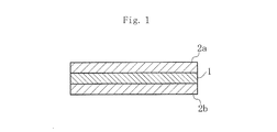
- FIG. 1 is a cross-sectional view schematically showing an embodiment of a solid ion capacitor according to the present invention.
- the solid ion capacitor has an anode 2 a and a cathode 2 b (electrode) on both main surfaces of a solid electrolyte 1. Is formed.
- the solid electrolyte 1 is made of a thin film body, contains an ion conductive compound, and the anode 2a and the cathode 2b contain substances containing ion conductive elements (hereinafter referred to as “specific element-containing substances”). And the volume content of the specific element-containing material in the anode 2a and the cathode 2b is less than 50 vol% (excluding 0 vol%).
- the solid electrolyte 1 into a thin film body, a large electrostatic capacity can be obtained, and even if charging / discharging is repeated by containing the specific element-containing substance in the anode 2a and the cathode 2b in the above-mentioned predetermined amount. It is possible to obtain a solid ion capacitor with good cycle characteristics in which a decrease in capacitance is suppressed.
- the capacitance in the conventional electric double layer capacitor, a voltage is applied only to a portion forming the electric double layer to accumulate electric charge, and the capacitance does not depend on the thickness of the electrolyte, so that the capacitance is increased. For this purpose, it is necessary to increase the electrode area. However, since there is a limit in increasing the electrode area, the capacitance can be obtained only about 25 ⁇ F / cm 2 in terms of specific capacity.
- the electric field application region in the solid electrolyte 1 can be increased, and thereby the electrostatic capacity can be increased without increasing the electrode area.
- the capacity can be greatly increased.
- FIG. 2A and 2B are diagrams for explaining the operation principle of the solid ion capacitor.
- FIG. 2A is a diagram schematically showing the solid ion capacitor
- FIG. 2B is an equivalent circuit of FIG. 2A.
- 2C shows the potential distribution of FIG. 2A, respectively.
- the solid electrolyte 1 only one of a cation or an anion moves in the solid, and the other ion forms a crystal lattice and does not move.
- the solid electrolyte 1 is formed of a cation conductive compound containing a cation such as Li ion, the cation moves in the solid electrolyte 1 even when a voltage is applied between the anode 2a and the cathode 2b.
- anions do not move easily from the crystal lattice.
- the potential distribution of the solid ion capacitor decreases substantially linearly from the anode 2a to the cathode 2b, and no flat portion is formed in the solid electrolyte 1, or the pole Only a short distance flat part is formed.
- the electric field application region can be increased by thinning the thickness of the solid electrolyte 1, and a single capacitor C is formed between the anode 2a and the cathode 2b with the solid electrolyte 1 interposed therebetween. It becomes possible to do. Further, since the polarization formed by the ions displaced by the electric field increases due to the increase in the electric field application region, the charges accumulated in the anode 2a and the cathode 2b increase, thereby greatly increasing the capacitance per volume. It becomes possible to make it.
- the thickness of the solid electrolyte 1 is not particularly limited as long as it is a thin film body that can secure a sufficient electric field application region when the electric field penetrates into the solid electrolyte 1 when an electric field is applied. It is preferable to form the following.
- the material for forming the solid electrolyte 1 is not particularly limited as long as it includes an ion conductive compound in which ions move in the solid electrolyte 1, but the apex of the regular octahedral structure and the regular tetrahedral structure are not limited. It is preferable to include a NASICON crystal structure in which the apex is shared and arranged three-dimensionally.
- the NASICON crystal structure has large voids in the crystal structure, and the cation moves easily, while the movement of the anion is extremely difficult.
- a mixed phase of NASICON crystal structure and AlPO 4 (berlinite) is more preferable.
- Li can be preferably used as the ion conductor element, and other components of the ion conductor compound are preferably used in the form of complex oxides containing Al, P, Ti, Ge, and the like. can do.
- Ceramics containing Li usually have hygroscopicity and are unstable with respect to moisture, but by containing a glass component, they show good stability with respect to moisture and improve moisture resistance. be able to.
- the anode 2a and the cathode 2b contain a specific element-containing material of less than 50 vol% (not including 0 vol%), thereby suppressing a decrease in capacitance even when charging and discharging are repeated.
- a solid ion capacitor having good cycle characteristics is obtained.
- the ion conductive element contained in the solid electrolyte 1 moves to the anode 2a and the cathode 2b side during charging and discharging.
- the ion conductive elements in the anode 2a and the cathode 2b suppress unintentional chemical reaction at the interface with the solid electrolyte 1, and thus the cycle characteristics with little decrease in capacitance even after repeated charge and discharge. Can be obtained.
- the content of the specific element-containing substance in the electrode is 50 vol% or more, it will also prevent the conduction of electrons without a chemical reaction that contributes to the acquisition of capacitance, so that a large capacitance can be stabilized. May be difficult to obtain.
- the content of the specific element-containing substance in the electrodes is adjusted to be less than 50 vol% (excluding 0 vol%), preferably 1 to 35 vol%. is doing.
- Such a specific element-containing substance is not particularly limited as long as it contains an ion conductive element.
- the electrode material used for the anode 2a and the anode 2b is not particularly limited, but a non-valve action material having no valve action, for example, a noble metal material such as Au, Pt, Pd, Ni, Cu, Cr, Transition metal materials such as Mn, Fe, and Co can be used preferably, and oxide materials and semiconductor materials such as SiC can also be used.
- a noble metal material such as Au, Pt, Pd, Ni, Cu, Cr, Transition metal materials such as Mn, Fe, and Co
- oxide materials and semiconductor materials such as SiC can also be used.
- valve action metal having a valve action such as Al, Ti, Ta, Nb, or an alloy containing these metals can be easily applied to the interface between the anode 2a or the anode 2b and the solid electrolyte 1 during the production of the solid ion capacitor. This is not preferable because an insulating layer may be formed and the capacitance may be reduced.
- the interface between the solid electrolyte 1 and the anode 2a or the cathode 2b has a fine uneven structure.
- the electrode area of the anode 2a or the cathode 2b is increased, so that the capacitance can be further increased in combination with the thinning of the solid electrolyte 1.
- the surface Since the solid electrolyte 1 is a sintered body formed by a firing process as will be described later, the surface has a certain uneven structure at the stage of sintering. After the polishing process is performed so that the surface has minute irregularities, the anode 2a or the cathode 2b is formed, or the anode 2a or the cathode 2b is formed without polishing the sintered body, thereby easily making the interface. A minute uneven structure can be obtained. In addition, the main surface of the solid electrolyte 1 can be appropriately etched to form a micro uneven structure.
- a predetermined amount of raw materials are weighed and mixed.
- a P compound such as PO 4 and a Ti compound such as TiO 2 are prepared, and a predetermined amount of these raw materials are weighed and mixed to obtain a mixture.
- this mixture is heat-treated with a predetermined heat-treatment profile to produce an ion conductive compound.
- a predetermined amount of a glass material containing a Si compound such as SiO 2 is weighed and mixed together with the raw materials, heated and melted, and then rapidly cooled to be vitrified. Then, it is preferable to heat-treat with the predetermined heat treatment profile to produce an ion conductive compound.
- the ion conductive compound is pulverized by a wet process, and then a binder, a solvent, a plasticizer, and the like are added and sufficiently mixed by a wet process to obtain a slurry. And after drying and granulating this slurry, it press-molds to a pellet shape etc. and obtains the molded object of a thin film.
- the binder, solvent, plasticizer, etc. are not particularly limited.
- polyvinyl butyral resin is used as the binder
- n-butyl acetate is used as the solvent
- dibutyl phthalate is used as the plasticizer. can do.
- the molded body is fired, for example, by setting the firing temperature to 400 ° C. to 1250 ° C. and the firing time to 3 to 70 hours, thereby producing the solid electrolyte 1 having a thin film body (for example, a thickness of 200 ⁇ m or less). To do.
- an electrode paste is prepared. That is, a specific element-containing material containing an ion conductive element, for example, a specific element-containing material such as Li or a Li compound is prepared. Further, as the conductive powder, preferably non-valve action material having no valve action, for example, noble metal material such as Au, Pt, Pd, transition metal material such as Ni, Cu, Cr, Mn, Fe, Co, oxidation A material material or a semiconductor material such as SiC is prepared.
- the total amount of the conductive powder and the specific element-containing substance that is, the volume content of the specific element-containing substance in the solid content is less than 50 vol% (excluding 0 vol%), preferably 1 to 35 vol%.
- the powder and the substance containing the specific element are weighed. Then, varnish and other additives are added to this weighed product, and a three-roll mill or the like is used to knead in an organic vehicle to form a paste, thereby producing an electrode paste.
- this electrode paste is applied to both main surfaces of the solid electrolyte 1, and then baked at a predetermined temperature to produce the anode 2a and the cathode 2b, thereby producing a solid ion capacitor.
- the specific element containing material is contained in the range of less than 50 vol% (excluding 0 vol%) in the anode 2a or the cathode 2b, the ion conduction in an ion conductive compound is carried out, respectively. Even if the conductive element moves to the electrode side during charging / discharging, the ion conductive element in the anode 2a and the cathode 2b is prevented from causing an unintended chemical reaction at the interface with the solid electrolyte 1, thereby repeating charging / discharging. However, it is possible to obtain a solid ion capacitor with good cycle characteristics with little decrease in capacitance.
- this invention is not limited to the said embodiment, It can deform
- a single plate-shaped solid ion capacitor is illustrated, but it is also preferable to have a multilayer structure similar to a multilayer ceramic capacitor. That is, a capacitor is formed by laminating a large number of capacitor bodies made of a solid electrolyte, an anode, and a cathode so that an anode is formed on one main surface of the solid electrolyte made of a thin film body and a cathode is formed on the other main surface.
- a main body and forming external electrodes on both ends of the capacitor main body By forming a main body and forming external electrodes on both ends of the capacitor main body, a multilayer structure similar to a multilayer ceramic capacitor is obtained, and a small solid ion capacitor having a larger capacitance can be easily realized. Can do.
- H 3 PO 4 , Li 2 CO 3 , Al (PO 3 ) 3 , SiO 2 , and TiO 2 were prepared as raw materials, and a predetermined amount of these raw materials were weighed and mixed to obtain a mixture.
- this mixture is put into a melting kiln, heated and melted at a temperature of 1500 ° C. for 3 hours, and the melted mixture is poured out from a slit-like hole provided at the bottom of the melting kiln to a mold at a temperature of 300 ° C. And rapidly cooled to obtain a glassy molded body.
- this glassy molded body was heat-treated with a predetermined heat treatment profile to obtain a Li ion conductive compound.
- the temperature of the heat treatment furnace is increased from room temperature to 600 ° C. at a temperature increase rate of 300 ° C./h, then increased to 950 ° C. at a temperature increase rate of 100 ° C./h, and then the heat treatment temperature is increased to 950 ° C. It was set and held for 10 hours, and then gradually cooled to room temperature, whereby a crystallized Li ion conductive compound was obtained.
- the component composition of the Li-ion conductive compound was measured using an ICP emission spectrometer (Thermo Fisher Scientific Inc. ICAP6300), the composition is a Li 1.21 Al 0.64 Ti 1.53 Si 0.16 P 2.82 O 12 It was confirmed.
- Li ion conductive compound is pulverized wet
- polyvinyl butyral resin as a binder, n-butyl acetate as a solvent, and dibutyl phthalate as a plasticizer are added and thoroughly mixed in a wet manner. A slurry was obtained. And after drying and granulating this slurry, it press-molded and produced the molded object.
- the molded body was fired at a firing temperature of 800 ° C. for 12 hours to obtain a sintered body.
- this sintered body was cut with a diamond cutter so as to have a thickness of 160 ⁇ m, and the surface was mirror-finished by mechanical polishing, thereby obtaining a solid electrolyte.
- the Pt paste, Pd paste, or Cu paste is applied to both main surfaces of the solid electrolyte and baked at a temperature of 600 ° C., thereby forming an anode and a cathode having a thickness of 1 ⁇ m.
- Each sample of ⁇ 21 was obtained.
- the electrode surface areas of the anode and the cathode were each 0.25 cm 2 .
- sample evaluation The samples Nos. 1 to 21 were charged and discharged with a predetermined charge / discharge profile using a constant voltage charge / discharge characteristic evaluation apparatus.
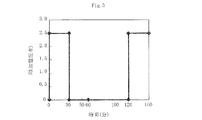
- FIG. 3 is a diagram showing the charge / discharge profile used in this example, where the horizontal axis represents time (minutes) and the vertical axis represents applied voltage (V).
- a constant voltage of 2.5 V was applied between the anode and the cathode, charged for 30 minutes, then discharged for 30 minutes, and the anode and cathode were short-circuited for another 60 minutes to maintain the discharge state.
- a charge / discharge cycle of applying a constant voltage of 0.5 V between the anode and the cathode and charging for 30 minutes was repeated 10 times.
- the short-circuit time is provided in order to prevent the measurement of the capacitance in the next cycle from being affected.
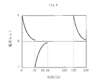
- FIG. 4 shows current characteristics during charging and discharging, where the horizontal axis is time (minutes) and the vertical axis is current (a.u).
- the specific capacity was obtained by integrating the current value at the time of discharge with time from this current characteristic, converting it to electric charge, calculating the electrostatic capacity from the amount of electric charge, and further dividing this electrostatic capacity by the electrode surface area.
- the specific capacity change rate ⁇ C was obtained from the initial value C1 of the specific capacity and the specific capacity C10 after 10 cycles.
- Table 1 shows the volume content of Li 2 O, the initial value C1 of the specific capacity, and the specific capacity change rate ⁇ C in sample numbers 1 to 21.
- Sample numbers 1 to 7 are samples using Pt paste.
- the initial value C1 of the specific capacity is 1027 to 1184 ⁇ F / cm 2 , which is a large specific capacity of 1000 ⁇ F / cm 2 or more. I was able to get it.
- Sample No. 1 had a specific capacity change rate ⁇ C of 74.5%, and it was found that the specific capacity decreased greatly when charging and discharging were repeated. This is because Li 2 O as a specific element-containing material in the electrode is not contained, Li contained in the solid electrolyte is moved to the interface between with an irreversible reaction during charging and discharging electrode or electrodes and the solid electrolyte Impurities are generated at the time, and as a result, it is considered that the capacitance decreases when charging and discharging are repeated.
- Sample No. 7 could measure the capacitance at the beginning of the cycle number, but could not measure the stable capacitance after 10 cycles. This is because the volume content of Li 2 O is excessive, which also hinders the conduction of electrons without a chemical reaction that contributes to the acquisition of capacitance, and therefore a stable capacitance could not be measured. I think that the.
- sample numbers 2 to 6 contain Li 2 O in a range of 35 vol% or less in the anode or cathode, Li in the anode and cathode causes an unintended chemical reaction at the interface with the solid electrolyte.
- the specific capacity change rate ⁇ C was smaller than that of the sample number 1, and it was found that the decrease in the specific capacity was suppressed even after 10 cycles.
- Sample numbers 8 to 14 are samples using Pd paste.
- the initial value C1 of the specific capacity is 1062 to 1254 ⁇ F / cm 2 , which is a large specific capacity of 1000 ⁇ F / cm 2 or more. I was able to get it.
- Sample No. 14 was able to measure the capacitance at the beginning of the number of cycles, but for the same reason as Sample No. 7, it was not possible to measure a stable capacitance after 10 cycles.
- Sample Nos. 9 to 13 contain Li 2 O in a range of 35 vol% or less in the anode or cathode, so that Li in the anode and cathode causes an unintended chemical reaction at the interface with the solid electrolyte.
- the specific capacity change rate ⁇ C was smaller than that of the sample No. 8, and the decrease in the specific capacity was suppressed even after 10 cycles.
- Sample numbers 15 to 21 are samples using Cu paste.
- the initial value C1 of the specific capacity is 964 to 1234 ⁇ F / cm 2 and a large specific capacity of 950 ⁇ F / cm 2 or more is obtained. I was able to.
- Sample No. 15 had a specific capacity change rate ⁇ C of 78.1%, and it was found that the specific capacity decreased greatly when charge and discharge were repeated for the same reason as Sample No. 1.
- Sample No. 21 was able to measure the capacitance at the beginning of the number of cycles, but for the same reason as Sample No. 7, it was not possible to measure a stable capacitance after 10 cycles.
- Sample Nos. 16 to 20 contain Li 2 O in a range of 35 vol% or less in the anode or cathode, so that Li in the anode and cathode causes an unintended chemical reaction at the interface with the solid electrolyte.
- the specific capacity change rate ⁇ C was smaller than that of the sample No. 8, and it was found that the decrease in the specific capacity was suppressed even after 10 cycles.
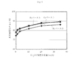
- FIG. 5 is a diagram showing the relationship between the Li 2 O volume content and the specific capacity change rate ⁇ C in the Pt paste, Pd paste, and Cu paste.
- the horizontal axis is the volume content (vol%) of Li 2 O, the vertical axis is the specific capacity change rate ⁇ C (%), and in the figure, ⁇ is Pt paste, ⁇ is Pd paste, and X is Cu paste is there.
- Example is only an example which actualized this invention, and is not limited to this Example.
- the same effect can be obtained even if an element such as Ge is added in addition to Ti or instead of Ti.
- a solid ion capacitor having a large capacitance and good cycle characteristics can be realized.
Landscapes
- Engineering & Computer Science (AREA)
- Power Engineering (AREA)
- Chemical & Material Sciences (AREA)
- Chemical Kinetics & Catalysis (AREA)
- Electrochemistry (AREA)
- Microelectronics & Electronic Packaging (AREA)
- Materials Engineering (AREA)
- Electric Double-Layer Capacitors Or The Like (AREA)
- Secondary Cells (AREA)
Abstract
Selon l'invention, une anode (2a) et une cathode (2b) sont formées sur les deux faces principales d'un électrolyte solide (1). L'électrolyte solide (1) tout en prenant de préférence la forme d'un corps de film fin d'épaisseur inférieure ou égale à 200µm, comprend un composé conducteur d'ions tel qu'un ion Li, ou similaire. En outre, une matière conductrice d'ions, par exemple Li2O, comprenant un élément chimique conducteur d'ions Li, ou similaire, est comprise dans l'anode (2a) et la cathode (2b), à raison de moins de 50% en volume (0% en volume inclus), et de préférence à raison de 1 à 35% en volume. Du fait de la mise en œuvre de l'électrolyte solide (1) en film fin, il est possible d'obtenir une importante capacité électrostatique avec une petite dimension, et de réaliser un condensateur d'ions solide possédant des caractéristiques de cycle satisfaisantes.
Priority Applications (3)
| Application Number | Priority Date | Filing Date | Title |
|---|---|---|---|
| JP2015528218A JP6172772B2 (ja) | 2013-07-23 | 2014-07-08 | 固体イオンキャパシタ |
| CN201480040102.4A CN105378869B (zh) | 2013-07-23 | 2014-07-08 | 固体离子电容器 |
| US15/001,421 US10186386B2 (en) | 2013-07-23 | 2016-01-20 | Solid ion capacitor |
Applications Claiming Priority (2)
| Application Number | Priority Date | Filing Date | Title |
|---|---|---|---|
| JP2013152625 | 2013-07-23 | ||
| JP2013-152625 | 2013-07-23 |
Related Child Applications (1)
| Application Number | Title | Priority Date | Filing Date |
|---|---|---|---|
| US15/001,421 Continuation US10186386B2 (en) | 2013-07-23 | 2016-01-20 | Solid ion capacitor |
Publications (1)
| Publication Number | Publication Date |
|---|---|
| WO2015012101A1 true WO2015012101A1 (fr) | 2015-01-29 |
Family
ID=52393149
Family Applications (1)
| Application Number | Title | Priority Date | Filing Date |
|---|---|---|---|
| PCT/JP2014/068217 Ceased WO2015012101A1 (fr) | 2013-07-23 | 2014-07-08 | Condensateur d'ions solide |
Country Status (4)
| Country | Link |
|---|---|
| US (1) | US10186386B2 (fr) |
| JP (1) | JP6172772B2 (fr) |
| CN (1) | CN105378869B (fr) |
| WO (1) | WO2015012101A1 (fr) |
Families Citing this family (2)
| Publication number | Priority date | Publication date | Assignee | Title |
|---|---|---|---|---|
| US10431849B2 (en) * | 2017-04-21 | 2019-10-01 | GM Global Technology Operations LLC | High energy density alkali metal batteries incorporating solid electrolytes |
| DE102019118190A1 (de) * | 2019-07-05 | 2021-01-07 | Bayerische Motoren Werke Aktiengesellschaft | Verfahren zur vorgegebenen polarisierung eines kondensators sowie kondensator mit vorgegebener isolierter polarisierung |
Citations (4)
| Publication number | Priority date | Publication date | Assignee | Title |
|---|---|---|---|---|
| JPH10154415A (ja) * | 1996-09-25 | 1998-06-09 | Tdk Corp | 高分子固体電解質およびこれを用いたリチウム2次電池と電気2重層キャパシタ |
| JP2008130844A (ja) * | 2006-11-21 | 2008-06-05 | Matsushita Electric Ind Co Ltd | 全固体型電気二重層コンデンサー |
| JP2012015119A (ja) * | 2006-03-30 | 2012-01-19 | Ohara Inc | リチウムイオン伝導性固体電解質の製造方法 |
| JP2013191769A (ja) * | 2012-03-14 | 2013-09-26 | Tohoku Univ | 固体電気二重層キャパシタ |
Family Cites Families (5)
| Publication number | Priority date | Publication date | Assignee | Title |
|---|---|---|---|---|
| US4977007A (en) * | 1986-09-19 | 1990-12-11 | Matsushita Electrical Indust. Co. | Solid electrochemical element and production process therefor |
| US4810599A (en) * | 1987-03-27 | 1989-03-07 | Japan Synthetic Rubber Co., Ltd. | Structure suitable for solid electrochemical elements |
| TW318288B (fr) * | 1995-02-21 | 1997-10-21 | Showa Denko Kk | |
| US6051343A (en) * | 1996-09-25 | 2000-04-18 | Tdk Corporation | Polymeric solid electrolyte and lithium secondary cell using the same |
| CN101388261A (zh) * | 2008-05-07 | 2009-03-18 | 北京理工大学 | 一种薄膜电解质及其制备方法 |
-
2014
- 2014-07-08 WO PCT/JP2014/068217 patent/WO2015012101A1/fr not_active Ceased
- 2014-07-08 JP JP2015528218A patent/JP6172772B2/ja not_active Expired - Fee Related
- 2014-07-08 CN CN201480040102.4A patent/CN105378869B/zh not_active Expired - Fee Related
-
2016
- 2016-01-20 US US15/001,421 patent/US10186386B2/en active Active
Patent Citations (4)
| Publication number | Priority date | Publication date | Assignee | Title |
|---|---|---|---|---|
| JPH10154415A (ja) * | 1996-09-25 | 1998-06-09 | Tdk Corp | 高分子固体電解質およびこれを用いたリチウム2次電池と電気2重層キャパシタ |
| JP2012015119A (ja) * | 2006-03-30 | 2012-01-19 | Ohara Inc | リチウムイオン伝導性固体電解質の製造方法 |
| JP2008130844A (ja) * | 2006-11-21 | 2008-06-05 | Matsushita Electric Ind Co Ltd | 全固体型電気二重層コンデンサー |
| JP2013191769A (ja) * | 2012-03-14 | 2013-09-26 | Tohoku Univ | 固体電気二重層キャパシタ |
Also Published As
| Publication number | Publication date |
|---|---|
| US20160141115A1 (en) | 2016-05-19 |
| JPWO2015012101A1 (ja) | 2017-03-02 |
| CN105378869A (zh) | 2016-03-02 |
| CN105378869B (zh) | 2019-03-26 |
| JP6172772B2 (ja) | 2017-08-02 |
| US10186386B2 (en) | 2019-01-22 |
Similar Documents
| Publication | Publication Date | Title |
|---|---|---|
| JP6315769B2 (ja) | 固体イオンキャパシタ、及び固体イオンキャパシタの使用方法 | |
| KR101553096B1 (ko) | 리튬 이온 2차 전지 및 그 제조 방법 | |
| JP5403066B2 (ja) | 固体電池 | |
| JP6596194B2 (ja) | 固体イオンキャパシタ | |
| JP5987103B2 (ja) | 全固体イオン二次電池 | |
| JP6801778B2 (ja) | 全固体電池 | |
| JP7568509B2 (ja) | 全固体二次電池 | |
| JP6209413B2 (ja) | 全固体電池の製造方法 | |
| JP2017182949A (ja) | 全固体電池用正極活物質材料の製造方法、全固体電池用正極活物質材料 | |
| JP6272613B2 (ja) | 全固体型キャパシタ | |
| JP6172772B2 (ja) | 固体イオンキャパシタ | |
| JP7365947B2 (ja) | 全固体リチウムイオン電池用ガーネット型固体電解質焼結体の製造方法及び全固体リチウムイオン電池の製造方法 | |
| JP7002199B2 (ja) | 全固体電池の製造方法 | |
| JP6554267B2 (ja) | 固体イオンキャパシタ | |
| JP2015065046A (ja) | 全固体電池およびその製造方法 | |
| WO2013073290A1 (fr) | Batterie tout solide et son procédé de fabrication | |
| JP2016174011A (ja) | 固体イオンキャパシタ | |
| WO2019004001A1 (fr) | Composite conducteur d'ions, batterie totalement solide, et procédé de production dudit composite et de ladite batterie | |
| JP6362883B2 (ja) | 固体イオンキャパシタおよび固体イオンキャパシタの製造方法 | |
| JP7070833B2 (ja) | 固体電解質シート及びその製造方法、並びに全固体二次電池 | |
| JP2015076573A (ja) | 全固体型電気二重層コンデンサ | |
| WO2025033068A1 (fr) | Batterie à semi-conducteurs | |
| JP6113266B2 (ja) | 全固体型キャパシタ | |
| CN121909513A (zh) | 固体电解质、固体电解质的制造方法以及电池 |
Legal Events
| Date | Code | Title | Description |
|---|---|---|---|
| ENP | Entry into the national phase |
Ref document number: 2015528218 Country of ref document: JP Kind code of ref document: A |
|
| NENP | Non-entry into the national phase |
Ref country code: DE |
|
| 121 | Ep: the epo has been informed by wipo that ep was designated in this application |
Ref document number: 14830211 Country of ref document: EP Kind code of ref document: A1 |
|
| 122 | Ep: pct application non-entry in european phase |
Ref document number: 14830211 Country of ref document: EP Kind code of ref document: A1 |