WO2015015929A1 - Dispositif d'affichage, système de régulation de puissance, procédé d'affichage, procédé de régulation de puissance, programme d'affichage et programme de régulation de puissance - Google Patents
Dispositif d'affichage, système de régulation de puissance, procédé d'affichage, procédé de régulation de puissance, programme d'affichage et programme de régulation de puissance Download PDFInfo
- Publication number
- WO2015015929A1 WO2015015929A1 PCT/JP2014/065824 JP2014065824W WO2015015929A1 WO 2015015929 A1 WO2015015929 A1 WO 2015015929A1 JP 2014065824 W JP2014065824 W JP 2014065824W WO 2015015929 A1 WO2015015929 A1 WO 2015015929A1
- Authority
- WO
- WIPO (PCT)
- Prior art keywords
- power
- devices
- display
- control
- setting value
- Prior art date
- Legal status (The legal status is an assumption and is not a legal conclusion. Google has not performed a legal analysis and makes no representation as to the accuracy of the status listed.)
- Ceased
Links
Images


Classifications
-
- G—PHYSICS
- G05—CONTROLLING; REGULATING
- G05F—SYSTEMS FOR REGULATING ELECTRIC OR MAGNETIC VARIABLES
- G05F1/00—Automatic systems in which deviations of an electric quantity from one or more predetermined values are detected at the output of the system and fed back to a device within the system to restore the detected quantity to its predetermined value or values, i.e. retroactive systems
- G05F1/66—Regulating electric power
-
- G—PHYSICS
- G01—MEASURING; TESTING
- G01R—MEASURING ELECTRIC VARIABLES; MEASURING MAGNETIC VARIABLES
- G01R21/00—Arrangements for measuring electric power or power factor
- G01R21/133—Arrangements for measuring electric power or power factor by using digital technique
-
- G—PHYSICS
- G05—CONTROLLING; REGULATING
- G05B—CONTROL OR REGULATING SYSTEMS IN GENERAL; FUNCTIONAL ELEMENTS OF SUCH SYSTEMS; MONITORING OR TESTING ARRANGEMENTS FOR SUCH SYSTEMS OR ELEMENTS
- G05B15/00—Systems controlled by a computer
- G05B15/02—Systems controlled by a computer electric
-
- G—PHYSICS
- G06—COMPUTING OR CALCULATING; COUNTING
- G06F—ELECTRIC DIGITAL DATA PROCESSING
- G06F3/00—Input arrangements for transferring data to be processed into a form capable of being handled by the computer; Output arrangements for transferring data from processing unit to output unit, e.g. interface arrangements
- G06F3/01—Input arrangements or combined input and output arrangements for interaction between user and computer
- G06F3/048—Interaction techniques based on graphical user interfaces [GUI]
- G06F3/0484—Interaction techniques based on graphical user interfaces [GUI] for the control of specific functions or operations, e.g. selecting or manipulating an object, an image or a displayed text element, setting a parameter value or selecting a range
- G06F3/04847—Interaction techniques to control parameter settings, e.g. interaction with sliders or dials
-
- G—PHYSICS
- G06—COMPUTING OR CALCULATING; COUNTING
- G06Q—INFORMATION AND COMMUNICATION TECHNOLOGY [ICT] SPECIALLY ADAPTED FOR ADMINISTRATIVE, COMMERCIAL, FINANCIAL, MANAGERIAL OR SUPERVISORY PURPOSES; SYSTEMS OR METHODS SPECIALLY ADAPTED FOR ADMINISTRATIVE, COMMERCIAL, FINANCIAL, MANAGERIAL OR SUPERVISORY PURPOSES, NOT OTHERWISE PROVIDED FOR
- G06Q10/00—Administration; Management
- G06Q10/06—Resources, workflows, human or project management; Enterprise or organisation planning; Enterprise or organisation modelling
-
- G—PHYSICS
- G06—COMPUTING OR CALCULATING; COUNTING
- G06Q—INFORMATION AND COMMUNICATION TECHNOLOGY [ICT] SPECIALLY ADAPTED FOR ADMINISTRATIVE, COMMERCIAL, FINANCIAL, MANAGERIAL OR SUPERVISORY PURPOSES; SYSTEMS OR METHODS SPECIALLY ADAPTED FOR ADMINISTRATIVE, COMMERCIAL, FINANCIAL, MANAGERIAL OR SUPERVISORY PURPOSES, NOT OTHERWISE PROVIDED FOR
- G06Q50/00—Information and communication technology [ICT] specially adapted for implementation of business processes of specific business sectors, e.g. utilities or tourism
- G06Q50/10—Services
- G06Q50/16—Real estate
-
- G—PHYSICS
- G06—COMPUTING OR CALCULATING; COUNTING
- G06T—IMAGE DATA PROCESSING OR GENERATION, IN GENERAL
- G06T11/00—Two-dimensional [2D] image generation
- G06T11/20—Drawing from basic elements
- G06T11/26—Drawing of charts or graphs
-
- H—ELECTRICITY
- H02—GENERATION; CONVERSION OR DISTRIBUTION OF ELECTRIC POWER
- H02J—ELECTRIC POWER NETWORKS; CIRCUIT ARRANGEMENTS OR SYSTEMS FOR SUPPLYING OR DISTRIBUTING ELECTRIC POWER; SYSTEMS FOR STORING ELECTRIC ENERGY
- H02J13/00—Circuit arrangements for providing remote monitoring or remote control of equipment in a power distribution network
- H02J13/10—Circuit arrangements for providing remote monitoring or remote control of equipment in a power distribution network characterised by displaying of information or by user interaction, e.g. supervisory control and data acquisition [SCADA] systems
-
- H—ELECTRICITY
- H02—GENERATION; CONVERSION OR DISTRIBUTION OF ELECTRIC POWER
- H02J—ELECTRIC POWER NETWORKS; CIRCUIT ARRANGEMENTS OR SYSTEMS FOR SUPPLYING OR DISTRIBUTING ELECTRIC POWER; SYSTEMS FOR STORING ELECTRIC ENERGY
- H02J13/00—Circuit arrangements for providing remote monitoring or remote control of equipment in a power distribution network
- H02J13/14—Circuit arrangements for providing remote monitoring or remote control of equipment in a power distribution network the power network being locally controlled, e.g. home energy management systems [HEMS]
-
- H—ELECTRICITY
- H02—GENERATION; CONVERSION OR DISTRIBUTION OF ELECTRIC POWER
- H02J—ELECTRIC POWER NETWORKS; CIRCUIT ARRANGEMENTS OR SYSTEMS FOR SUPPLYING OR DISTRIBUTING ELECTRIC POWER; SYSTEMS FOR STORING ELECTRIC ENERGY
- H02J3/00—Circuit arrangements for AC mains or AC distribution networks
- H02J3/12—Arrangements for adjusting voltage in AC networks by changing a characteristic of the network load
- H02J3/14—Arrangements for adjusting voltage in AC networks by changing a characteristic of the network load by switching loads on to, or off from, the networks, e.g. progressively balanced loading
-
- H—ELECTRICITY
- H02—GENERATION; CONVERSION OR DISTRIBUTION OF ELECTRIC POWER
- H02J—ELECTRIC POWER NETWORKS; CIRCUIT ARRANGEMENTS OR SYSTEMS FOR SUPPLYING OR DISTRIBUTING ELECTRIC POWER; SYSTEMS FOR STORING ELECTRIC ENERGY
- H02J2105/00—Networks for supplying or distributing electric power characterised by their spatial reach or by the load
- H02J2105/40—Networks for supplying or distributing electric power characterised by their spatial reach or by the load characterised by the loads connecting to the networks or being supplied by the networks
- H02J2105/42—Home appliances
-
- Y—GENERAL TAGGING OF NEW TECHNOLOGICAL DEVELOPMENTS; GENERAL TAGGING OF CROSS-SECTIONAL TECHNOLOGIES SPANNING OVER SEVERAL SECTIONS OF THE IPC; TECHNICAL SUBJECTS COVERED BY FORMER USPC CROSS-REFERENCE ART COLLECTIONS [XRACs] AND DIGESTS
- Y02—TECHNOLOGIES OR APPLICATIONS FOR MITIGATION OR ADAPTATION AGAINST CLIMATE CHANGE
- Y02B—CLIMATE CHANGE MITIGATION TECHNOLOGIES RELATED TO BUILDINGS, e.g. HOUSING, HOUSE APPLIANCES OR RELATED END-USER APPLICATIONS
- Y02B70/00—Technologies for an efficient end-user side electric power management and consumption
- Y02B70/30—Systems integrating technologies related to power network operation and communication or information technologies for improving the carbon footprint of the management of residential or tertiary loads, i.e. smart grids as climate change mitigation technology in the buildings sector, including also the last stages of power distribution and the control, monitoring or operating management systems at local level
- Y02B70/3225—Demand response systems, e.g. load shedding, peak shaving
-
- Y—GENERAL TAGGING OF NEW TECHNOLOGICAL DEVELOPMENTS; GENERAL TAGGING OF CROSS-SECTIONAL TECHNOLOGIES SPANNING OVER SEVERAL SECTIONS OF THE IPC; TECHNICAL SUBJECTS COVERED BY FORMER USPC CROSS-REFERENCE ART COLLECTIONS [XRACs] AND DIGESTS
- Y02—TECHNOLOGIES OR APPLICATIONS FOR MITIGATION OR ADAPTATION AGAINST CLIMATE CHANGE
- Y02B—CLIMATE CHANGE MITIGATION TECHNOLOGIES RELATED TO BUILDINGS, e.g. HOUSING, HOUSE APPLIANCES OR RELATED END-USER APPLICATIONS
- Y02B90/00—Enabling technologies or technologies with a potential or indirect contribution to GHG emissions mitigation
- Y02B90/20—Smart grids as enabling technology in buildings sector
-
- Y—GENERAL TAGGING OF NEW TECHNOLOGICAL DEVELOPMENTS; GENERAL TAGGING OF CROSS-SECTIONAL TECHNOLOGIES SPANNING OVER SEVERAL SECTIONS OF THE IPC; TECHNICAL SUBJECTS COVERED BY FORMER USPC CROSS-REFERENCE ART COLLECTIONS [XRACs] AND DIGESTS
- Y04—INFORMATION OR COMMUNICATION TECHNOLOGIES HAVING AN IMPACT ON OTHER TECHNOLOGY AREAS
- Y04S—SYSTEMS INTEGRATING TECHNOLOGIES RELATED TO POWER NETWORK OPERATION, COMMUNICATION OR INFORMATION TECHNOLOGIES FOR IMPROVING THE ELECTRICAL POWER GENERATION, TRANSMISSION, DISTRIBUTION, MANAGEMENT OR USAGE, i.e. SMART GRIDS
- Y04S20/00—Management or operation of end-user stationary applications or the last stages of power distribution; Controlling, monitoring or operating thereof
- Y04S20/20—End-user application control systems
- Y04S20/222—Demand response systems, e.g. load shedding, peak shaving
-
- Y—GENERAL TAGGING OF NEW TECHNOLOGICAL DEVELOPMENTS; GENERAL TAGGING OF CROSS-SECTIONAL TECHNOLOGIES SPANNING OVER SEVERAL SECTIONS OF THE IPC; TECHNICAL SUBJECTS COVERED BY FORMER USPC CROSS-REFERENCE ART COLLECTIONS [XRACs] AND DIGESTS
- Y04—INFORMATION OR COMMUNICATION TECHNOLOGIES HAVING AN IMPACT ON OTHER TECHNOLOGY AREAS
- Y04S—SYSTEMS INTEGRATING TECHNOLOGIES RELATED TO POWER NETWORK OPERATION, COMMUNICATION OR INFORMATION TECHNOLOGIES FOR IMPROVING THE ELECTRICAL POWER GENERATION, TRANSMISSION, DISTRIBUTION, MANAGEMENT OR USAGE, i.e. SMART GRIDS
- Y04S20/00—Management or operation of end-user stationary applications or the last stages of power distribution; Controlling, monitoring or operating thereof
- Y04S20/20—End-user application control systems
- Y04S20/242—Home appliances
Definitions
- the present invention relates to a display device, a power control system, a display method, a power control method, a display program, and a power control program used in a power consumption system including a plurality of devices.
- Such power control systems include, for example, HEMS (Home Energy Management System) for controlling household power, BEMS (Building Energy Management System) for controlling building power, and CEMS (Local Energy Management) such as local governments.
- HEMS Home Energy Management System
- BEMS Building Energy Management System
- CEMS Local Energy Management
- the purpose of these power control systems is to increase the efficiency of power use or actively use natural energy (solar, wind, geothermal, etc.) to form a sustainable society.
- power control has meant power control on the supply side of a power plant or the like.
- demand side management There are several types of demand-side management.
- power pricing is controlled with the aim of reducing the price as much as possible in response to dynamic pricing that changes the electricity price according to the time, or the peak at the peak of power demand is cut off to prevent failures such as power outages.
- the power demand is controlled to avoid the problem.
- Electric power that can be used as an upper limit (hereinafter simply referred to as “upper limit power”) is notified to each building. Each building is recommended to keep power consumption within the upper power limit notified.
- the demand to control demand for the upper limit power is expected to increase in the future.
- the method currently used in BEMS is to pre-determine whether or not to stop at the time of power saving request for each building equipment (air conditioner, lighting, elevator, etc.). This is a method of stopping a device planned in advance according to the upper limit power. It seems that demand control can be easily done in this way, but whether it is comfortable for people in the building is another story. Some equipment in the building cannot control power. For example, in a building where commercial facilities are integrated, it is desirable not to conserve equipment in commercial facilities as much as possible. This is because customers will leave if they save electricity that makes them uncomfortable. In such a case, equipment in a commercial facility is not subject to power control.
- the electric power used by the commercial facility is constantly fluctuating, and the demand control is performed such that the maximum amount of electric power used by the commercial facility is estimated and the device is stopped in anticipation of safety. Even when the commercial facility is not using the maximum amount of power, the floor where the equipment is controlled continues to save power excessively. In other words, the power saving request can be satisfied, but if the power is saved more than necessary, it will save the people in the building. In addition, there are cases where devices that are not planned to be shut down are turned off, so extra power will be saved including those devices.
- the current demand control examines in advance a plan for forecasting demand and supply, and when to use and when to stop the equipment, and performs control according to the plan.
- Patent Document 1 discloses an apparatus that manages the total power consumption of devices in an environment where one or more devices that consume power exist. In this device, it is possible to control power consumption optimally by learning and grading the usage status of devices and by learning and patterning consumer information.
- Patent Document 1 employs a configuration that simultaneously displays the merits and demerits expected to be brought to consumers by controlling the power consumption.
- Patent Document 2 assumes that there is a fixed functional relationship between the power demand and the power price.
- a “power transaction risk management method” is disclosed that uses a non-arbitrary principle to derive a differential equation that governs the price of derivative securities written on such a stochastic process.
- Patent Document 3 measures and compares the notified power reduction amount with the power amount reduced after being controlled, and compares and determines so as to achieve the power reduction amount.
- Patent Document 4 Japanese Patent Application Laid-Open No. 2010-124605 (Patent Document 4) compares power consumption data with each other and applies an evaluation function to extract power consumption data having a high correlation value from actual data. Apparatus ".
- JP 2010-146387 A Patent Document 5
- an energy saving action evaluation unit acquires data of yesterday and last week from a device information database, evaluates it using an evaluation function, and records this evaluation value in an evaluation result database.
- An “energy saving action evaluation device” is disclosed.
- the main reasons for making it difficult to realize demand control are as follows.
- the first reason is that there are many devices to be controlled (controllable devices).
- the second reason is that it is not possible to follow a real-time fluctuation in the power of a device that is not a control target (a device that cannot be controlled).
- the number of air conditioners, lighting, etc. that need to be controlled reaches 1000 levels, and the number of objects to be controlled will increase further in response to requests for power saving in cooperation between buildings.
- the CEMS level a device having a level 10 times that of BEMS will be controlled.
- An object of the present invention is to provide a display device, a power control system, a display method, a power control method, a display program, and a power control program that solve the above-described problems.
- a display device includes a storage unit that stores display information according to a degree of deviation between a user's desired value and a set value, and a display that displays the display information according to the degree of deviation. It has the display part characterized by this.
- a display device is a display device that communicates with a power control device that controls the power of a power consumption system including a plurality of devices, and each of the plurality of devices or a plurality of devices.
- An evaluation unit set for a plurality of devices when an input unit for specifying a desired setting value for the power consumption system and an upper limit power amount for the entire power consumption system including the plurality of devices are set. Real-time display contents corresponding to the degree of divergence calculated based on the comparison between the actual setting value of multiple devices whose power is demand-controlled based on the function and the desired setting value specified by the input unit And a display unit for displaying on the screen.
- FIG. 1 is a schematic configuration diagram showing an entire power control system according to an embodiment of the present invention.
- FIG. 2 is a block diagram for explaining a configuration of a display device according to an embodiment of the present invention.
- FIG. 3 is a block diagram for explaining the configuration of the power control apparatus according to the embodiment of the present invention.
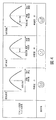
- FIG. 4 is a diagram for explaining an example of display contents displayed on the display unit of the display device shown in FIG.
- FIG. 5 is a diagram for explaining a control result obtained by using the power control apparatus according to the embodiment of the present invention.
- controllable device when the controllable device is an air conditioner, the air conditioner is not always operating toward the set temperature desired by the user. Further, when the controllable device is a lighting fixture, the device does not always operate so as to have the illuminance desired by the user.
- electric devices such as air conditioners and lighting fixtures are often controlled by a remote controller (hereinafter abbreviated as a remote controller).
- a remote controller used for a normal air conditioner, lighting fixture, or the like is configured to control the air conditioner or lighting fixture so as to match a set temperature, set illuminance, or the like desired by the user. For this reason, even when a normal remote control is applied to a device controlled by the power control apparatus shown in Japanese Patent Application No.
- FIG. 1 is a diagram illustrating a schematic configuration of a power control system 1 to which the power control apparatus according to the present embodiment can be applied.
- the illustrated power control system 1 includes a power consumption system 100 including a plurality of devices arranged in a building, a cloud (including a power control device 10 (see FIG. 2) configured on the cloud) 130, and a communication network. And a display device 20 according to the present invention that communicates with a plurality of devices and the power control device 10 built on the cloud.
- the power consumption system 100 includes a large number of lamps 102, a large number of air conditioners 104, and a plurality of elevators 106 as devices.
- FIG. 1 is a diagram illustrating a schematic configuration of a power control system 1 to which the power control apparatus according to the present embodiment can be applied.
- the illustrated power control system 1 includes a power consumption system 100 including a plurality of devices arranged in a building, a cloud (including a power control device 10 (see FIG. 2) configured on the cloud) 130
- a “non-control device group” surrounded by a dotted line is a device 110 that is not a control target (a device that is not a control target). Other than that is the control object 120.
- the non-controllable device (device not controlled) 110 is also referred to as “uncontrollable device”, and the control target 120 is also referred to as “controllable device”. That is, a large number of devices are divided into controllable devices 120 and uncontrollable devices 110.
- the present invention when there are a large number of devices 102, 104, and 106 in the power consumption system 100, satisfies the upper limit power while taking into account power fluctuations of the devices 110 that are not controlled.
- the device needs to be prioritized.
- the priorities the higher priority is given to the things that are important for the person or person who works in the building. That is, even if a device is stopped under a power saving request, it is possible to create a situation in which a device with a high priority is difficult to stop, and control can be performed that does not hinder the activities of objects and people to the maximum.
- the priority of whether to stop or not stop the equipment under the power limit varies depending on the floor characteristics even for the same equipment. For example, the priority of the air conditioner 104 in the server room is high, but the priority of the lamp 102 is low.
- the priority of the office floor lamp 102 is higher than the priority of the server room lamp 102. If finer control is considered, it is possible to raise the priority of the air conditioner 104 on the floor with many people and lower the priority of the air conditioner 104 on the floor with few people. In this way, the priorities of the equipment in the building are diverse.
- the most easily conceived method for controlling by assigning priority to devices is a method in which priorities are arranged according to the number of devices. Such may be possible if the number of devices is limited or the priority is obvious. However, in the actual case, the number of devices is enormous and many of them have the same level of priority. In addition, the priority of devices may change immediately due to layout changes, such as in the case of buildings.
- the present invention applies the “autonomous distributed load distribution method” filed by the present applicant.
- the present applicant has applied for an invention relating to a technique for controlling a plurality of elements in an autonomous distributed manner and performing an overall optimum load distribution.
- the element may be a server, a generator, or the like.
- the device to be subjected to power control corresponds to the element.
- the autonomous distributed load balancing method first, an evaluation function for the performance of each element is set for each element. Details of the outline of the evaluation function, the setting of the evaluation function, the autonomous distributed load distribution method using the evaluation function, and the like are described in detail in Japanese Patent Application No. 2013-131342, which is a related application.
- An upper limit electric energy is set to Dem.
- ⁇ i is the power of the controllable device i
- f i is a set evaluation function of the controllable device i
- ⁇ k is the power of the controllable neighboring device k
- f k is the controllable neighbor.
- the evaluation functions, K 1 and K 2 set for the device k represent the gains of power change, respectively.
- a control unit (power control device) 10 configured on the cloud 130 includes an information acquisition unit 12, a demand control unit 14, and an information transmission unit 16.
- the information acquisition unit 12 acquires the power of the building-controllable device 120 and the current power of the entire building, and passes it to the demand control unit 14.
- the demand control unit 14 can execute the above formula 1, and calculates the control value (temperature and number) at the next time of each controllable device 120 using the formula 1.
- the demand control unit 14 approximates these values to values that can be actually controlled, and outputs them to the information transmission unit 16.
- the information transmission unit 16 transmits the received control value of the next time of each controllable device 120 to each controllable device 120. Thereafter, the above process is repeated.
- FIG. 3 shows a schematic configuration of the display device 20 according to the present embodiment.
- the display device 20 is, for example, a remote controller, a smartphone, or the like, and is a device that can communicate with another device (here, the power control device 10 illustrated in FIG. 2).
- the illustrated display device 20 includes an input unit 22, a communication unit 24, and a display unit 26.
- the input unit 22 includes buttons and a touch panel for designating desired setting values of a user (subject) for a plurality of devices.
- the communication unit 24 transmits the specified desired setting value to the power control apparatus 10.
- the communication unit 24 includes a transmitter / receiver that transmits / receives an infrared ray or a radio signal, and includes an actual setting value of each device controlled under demand control in the power control device 10 and a desired setting value specified by the user. Display information corresponding to the degree of divergence is received and displayed on the display unit 26 composed of liquid crystal, organic EL, or the like.
- the illustrated display device 20 includes a control unit 28 that controls the input unit 22, the communication unit 24, and the display unit 26.
- the control unit 28 includes a storage unit that stores a program and a CPU.
- the input unit 22, the communication unit 24, and the display unit 26 are controlled in accordance with a program stored in the storage device. Specifically, when a user's desired value is input from the input unit 22 and an actual setting value is received from the power control apparatus 10 through the communication unit 24, the control unit 28 determines the degree of divergence between the desired value and the actual setting value. Is calculated. The degree of divergence calculated by the control unit 28 is given to the display unit 26.
- the display unit 26 includes a display information storage unit 261, and the display information storage unit 261 displays display information corresponding to the degree of deviation on the display 263.
- the display information corresponding to the degree of divergence displayed on the display 263 represents, for example, the comfort level. For example, display contents such as face marks and characters shown in FIG.
- FIG. 4 is a diagram for explaining the relationship between the setting by demand control and the display example of the display unit 26 of the display device 20 in an environment where the upper limit power is set. As shown in the figure, when the difference between the desired setting value specified by the user and the actual setting value of the plurality of devices whose power consumption is demand-controlled based on the evaluation function set for the plurality of devices is small, that is, the difference When the degree is small, for example, a smile mark is displayed on the display unit 26.
- the present invention is not limited to the face mark and may be displayed by a symbol or a character.
- the display device 20 and the power control system 1 when the upper limit power amount for the entire power consumption system is set, demand control is performed on a plurality of devices based on the evaluation function, and the degree of divergence The current convenience and comfort are displayed to the user.
- the present invention is not limited to this.
- a power control device is provided corresponding to the air conditioner 104 or the plurality of lamps 102 shown in FIG. 1, the same applies to the case where these power control devices communicate with the display device 20.
- the power control method executed by the power control apparatus includes a floppy (registered trademark) disk, a magnetic disk such as a hard disk, an optical disk such as a CD-ROM and a DVD, and a magneto-optical disk as programs that can be executed by a computer.
- the control unit 28 of the display device 20 also includes a program for displaying display information corresponding to the degree of divergence, and this program may also be stored in a recording medium or the like, or downloaded through the net.
- the recording medium can store a program and can be read by a computer
- the storage format may be any form.
- an operating system running on the computer middleware such as database management software, network software, or the like may execute a part of each process based on an instruction of a program installed in the computer from the recording medium.
- the recording medium is not limited to a medium independent of a computer, but also includes a recording medium in which a program transmitted via a LAN or the Internet is downloaded and stored or temporarily stored.
- the number of recording media is not limited to one, and the case where the processing in the above embodiment is executed from a plurality of media is also included in the recording media in the present invention, and the media configuration may be any configuration.
- the computer executes each process based on a program stored in a recording medium, and may have any configuration such as a device including a personal computer or a system in which a plurality of devices are connected to a network.
- the computer is not limited to a personal computer, but includes an arithmetic processing device included in an information processing device, and is a device or device capable of realizing the functions of the present invention by a program. While the present invention has been described with reference to the embodiments, the present invention is not limited to the above embodiments. Various changes that can be understood by those skilled in the art can be made to the configuration and details of the present invention within the scope of the present invention. In the above-described embodiment, an example of BEMS that is power control of a building has been shown, but it is naturally possible to do the same with other energy management such as HEMS and CEMS. In the first embodiment, control is performed by uploading data to a server on the cloud.
- control is not limited to the cloud, and the same control may be performed by placing the server in a building or a house.
- This application claims the priority on the basis of Japanese application Japanese Patent Application No. 2013-157762 for which it applied on July 30, 2013, and takes in those the indications of all here.
- Control System 10 Control Unit (Power Control Device) 12 Information acquisition unit 14 Demand control unit 16 Information transmission unit 20 Display device 22 Input unit 24 Communication unit 26 Display unit 261 Display information storage unit 263 Display 28 Control unit 100 Power consumption system 102 Electric light 104 Air conditioner 106 Elevator 110 Non-control device group ( Uncontrollable equipment) 120 Control target (controllable equipment) 130 cloud
Landscapes
- Engineering & Computer Science (AREA)
- Business, Economics & Management (AREA)
- Physics & Mathematics (AREA)
- General Physics & Mathematics (AREA)
- Power Engineering (AREA)
- Theoretical Computer Science (AREA)
- Strategic Management (AREA)
- Economics (AREA)
- Human Resources & Organizations (AREA)
- Tourism & Hospitality (AREA)
- Entrepreneurship & Innovation (AREA)
- General Business, Economics & Management (AREA)
- Marketing (AREA)
- General Engineering & Computer Science (AREA)
- Automation & Control Theory (AREA)
- Electromagnetism (AREA)
- Radar, Positioning & Navigation (AREA)
- Operations Research (AREA)
- Quality & Reliability (AREA)
- Game Theory and Decision Science (AREA)
- Health & Medical Sciences (AREA)
- General Health & Medical Sciences (AREA)
- Primary Health Care (AREA)
- Educational Administration (AREA)
- Development Economics (AREA)
- Human Computer Interaction (AREA)
- Remote Monitoring And Control Of Power-Distribution Networks (AREA)
- Supply And Distribution Of Alternating Current (AREA)
- Selective Calling Equipment (AREA)
- Management, Administration, Business Operations System, And Electronic Commerce (AREA)
Abstract
Priority Applications (2)
| Application Number | Priority Date | Filing Date | Title |
|---|---|---|---|
| US14/908,880 US20160170428A1 (en) | 2013-07-30 | 2014-06-10 | Display device, power control system, display method, power control method, display program, and power control program |
| JP2015529448A JP6358443B2 (ja) | 2013-07-30 | 2014-06-10 | 表示装置、電力制御システム、表示方法、電力制御方法、表示プログラム、及び電力制御プログラム |
Applications Claiming Priority (2)
| Application Number | Priority Date | Filing Date | Title |
|---|---|---|---|
| JP2013157662 | 2013-07-30 | ||
| JP2013-157662 | 2013-07-30 |
Publications (1)
| Publication Number | Publication Date |
|---|---|
| WO2015015929A1 true WO2015015929A1 (fr) | 2015-02-05 |
Family
ID=52431472
Family Applications (1)
| Application Number | Title | Priority Date | Filing Date |
|---|---|---|---|
| PCT/JP2014/065824 Ceased WO2015015929A1 (fr) | 2013-07-30 | 2014-06-10 | Dispositif d'affichage, système de régulation de puissance, procédé d'affichage, procédé de régulation de puissance, programme d'affichage et programme de régulation de puissance |
Country Status (3)
| Country | Link |
|---|---|
| US (1) | US20160170428A1 (fr) |
| JP (1) | JP6358443B2 (fr) |
| WO (1) | WO2015015929A1 (fr) |
Cited By (4)
| Publication number | Priority date | Publication date | Assignee | Title |
|---|---|---|---|---|
| JP2017016564A (ja) * | 2015-07-06 | 2017-01-19 | 日本電気株式会社 | 制御装置、その制御方法、およびプログラム |
| JP2017038501A (ja) * | 2015-08-12 | 2017-02-16 | 株式会社東芝 | エネルギー管理装置、エネルギー管理方法及びエネルギー管理プログラム |
| WO2019167138A1 (fr) * | 2018-02-27 | 2019-09-06 | アビームコンサルティング株式会社 | Dispositif d'aide à la réduction d'énergie, programme, et support d'enregistrement sur lequel un programme est enregistré |
| WO2024095374A1 (fr) * | 2022-11-01 | 2024-05-10 | 三菱電機ビルソリューションズ株式会社 | Système de gestion d'énergie et procédé de gestion d'énergie |
Families Citing this family (10)
| Publication number | Priority date | Publication date | Assignee | Title |
|---|---|---|---|---|
| JP5891931B2 (ja) * | 2012-04-27 | 2016-03-23 | ソニー株式会社 | 表示制御装置、表示制御方法、表示制御プログラムおよび携帯端末 |
| JP6296251B2 (ja) * | 2013-06-24 | 2018-03-20 | 日本電気株式会社 | 電力制御装置、方法、およびプログラム |
| US10205320B2 (en) * | 2013-12-24 | 2019-02-12 | Kyocera Corporation | Power management apparatus, power management system, and power management method |
| JP5967265B2 (ja) * | 2014-07-31 | 2016-08-10 | ダイキン工業株式会社 | 機器制御装置 |
| CA2929791C (fr) | 2015-05-12 | 2023-01-03 | The Toronto-Dominion Bank | Attribution de ressource fondee sur les appareils connectes |
| US10938700B2 (en) * | 2015-05-12 | 2021-03-02 | The Toronto-Dominion Bank | Resource allocation control based on connected devices |
| CA2944369C (fr) | 2015-10-29 | 2022-01-25 | The Toronto-Dominion Bank | Controle de transfert de donnees fonde sur l'analyse d'utilisation de dispositif connecte |
| US10460748B2 (en) | 2017-10-04 | 2019-10-29 | The Toronto-Dominion Bank | Conversational interface determining lexical personality score for response generation with synonym replacement |
| US10339931B2 (en) | 2017-10-04 | 2019-07-02 | The Toronto-Dominion Bank | Persona-based conversational interface personalization using social network preferences |
| US10859993B1 (en) * | 2020-01-29 | 2020-12-08 | Capital One Services, Llc | System and method for control of smart appliance operation |
Citations (1)
| Publication number | Priority date | Publication date | Assignee | Title |
|---|---|---|---|---|
| JP2010187453A (ja) * | 2009-02-11 | 2010-08-26 | Chubu Electric Power Co Inc | 集合住宅用の車両充電システム及び充電制御装置 |
Family Cites Families (10)
| Publication number | Priority date | Publication date | Assignee | Title |
|---|---|---|---|---|
| JPH09154186A (ja) * | 1995-11-30 | 1997-06-10 | Nippon Seiki Co Ltd | 表示装置 |
| JP2000050500A (ja) * | 1998-07-28 | 2000-02-18 | Naigai Denki Kk | デマンド制御方法 |
| JP4749455B2 (ja) * | 2008-09-24 | 2011-08-17 | 三菱電機株式会社 | 電気機器用通信アダプタ |
| CN103221755B (zh) * | 2010-12-28 | 2016-10-19 | 欧姆龙株式会社 | 空调信息推定装置、空调信息推定装置的控制方法、以及控制程序 |
| GB2479060B (en) * | 2011-03-24 | 2012-05-02 | Reactive Technologies Ltd | Energy consumption management |
| WO2012160978A1 (fr) * | 2011-05-23 | 2012-11-29 | 日本電気株式会社 | Système et procédé de commande de système |
| KR20130058909A (ko) * | 2011-11-28 | 2013-06-05 | 엘지전자 주식회사 | 공기 조화기 및 그 제어방법 |
| US9879872B2 (en) * | 2012-06-15 | 2018-01-30 | Mitsubishi Electric Corporation | Air-conditioning management device, air-conditioning management method, and program |
| US9638730B2 (en) * | 2012-12-21 | 2017-05-02 | Nihon Techno Co., Ltd. | Demand target display device |
| US9477240B2 (en) * | 2013-04-29 | 2016-10-25 | Eaton Corporation | Centralized controller for intelligent control of thermostatically controlled devices |
-
2014
- 2014-06-10 US US14/908,880 patent/US20160170428A1/en not_active Abandoned
- 2014-06-10 JP JP2015529448A patent/JP6358443B2/ja not_active Expired - Fee Related
- 2014-06-10 WO PCT/JP2014/065824 patent/WO2015015929A1/fr not_active Ceased
Patent Citations (1)
| Publication number | Priority date | Publication date | Assignee | Title |
|---|---|---|---|---|
| JP2010187453A (ja) * | 2009-02-11 | 2010-08-26 | Chubu Electric Power Co Inc | 集合住宅用の車両充電システム及び充電制御装置 |
Cited By (7)
| Publication number | Priority date | Publication date | Assignee | Title |
|---|---|---|---|---|
| JP2017016564A (ja) * | 2015-07-06 | 2017-01-19 | 日本電気株式会社 | 制御装置、その制御方法、およびプログラム |
| JP2017038501A (ja) * | 2015-08-12 | 2017-02-16 | 株式会社東芝 | エネルギー管理装置、エネルギー管理方法及びエネルギー管理プログラム |
| WO2019167138A1 (fr) * | 2018-02-27 | 2019-09-06 | アビームコンサルティング株式会社 | Dispositif d'aide à la réduction d'énergie, programme, et support d'enregistrement sur lequel un programme est enregistré |
| JP6584720B1 (ja) * | 2018-02-27 | 2019-10-02 | アビームコンサルティング株式会社 | エネルギー削減支援装置、プログラム及びプログラムを記録した記録媒体 |
| WO2024095374A1 (fr) * | 2022-11-01 | 2024-05-10 | 三菱電機ビルソリューションズ株式会社 | Système de gestion d'énergie et procédé de gestion d'énergie |
| JP7546819B1 (ja) * | 2022-11-01 | 2024-09-06 | 三菱電機ビルソリューションズ株式会社 | 電力管理システムおよび電力管理方法 |
| GB2639341A (en) * | 2022-11-01 | 2025-09-24 | Mitsubishi Electric Corp | Power management system and power management method |
Also Published As
| Publication number | Publication date |
|---|---|
| JP6358443B2 (ja) | 2018-07-18 |
| US20160170428A1 (en) | 2016-06-16 |
| JPWO2015015929A1 (ja) | 2017-03-02 |
Similar Documents
| Publication | Publication Date | Title |
|---|---|---|
| JP6358443B2 (ja) | 表示装置、電力制御システム、表示方法、電力制御方法、表示プログラム、及び電力制御プログラム | |
| King et al. | Smart buildings: Using smart technology to save energy in existing buildings | |
| US20150241895A1 (en) | Tablet based distributed intelligent load management | |
| JP6181263B2 (ja) | エネルギー管理装置およびエネルギー管理方法 | |
| Lawrence et al. | A new paradigm for the design and management of building systems | |
| US9852484B1 (en) | Providing demand response participation | |
| JP6150057B2 (ja) | 電力制御装置、方法及びプログラム、並びに優先度決定装置、方法及びプログラム | |
| JP5700871B2 (ja) | 電力需要制御システム及び方法 | |
| JP6116970B2 (ja) | エネルギー管理システム、エネルギー管理装置及びエネルギー管理方法 | |
| JP2015033199A (ja) | 情報処理装置及びサービス提供方法 | |
| JP6296251B2 (ja) | 電力制御装置、方法、およびプログラム | |
| Vanage et al. | Grid-scale demand-side flexibility services using commercial buildings lighting loads | |
| Johnson | Controlling and optimizing resilient distributed energy resources and microgrids with a demand-side operation platform | |
| Wang et al. | Customer-centered control system for intelligent and green building with heuristic optimization | |
| Jin et al. | A fast building demand response method based on supply–demand coordination for urgent responses to smart grids | |
| JP6150058B2 (ja) | 電力制御装置、電力制御システム、制御可能な機器、方法、およびプログラム | |
| Al-Saedi | Peak shaving energy management system for smart house | |
| JP2019187096A (ja) | 調整電力量推定システム及び調整電力量推定システムの制御方法 | |
| JP6098026B2 (ja) | 電力制御システム、プログラムおよび電力制御装置 | |
| JP5935003B2 (ja) | 電力制御装置、電力管理システムおよびプログラム | |
| JP2023177474A (ja) | 電力管理システム及び電力管理方法 | |
| Ramamritham et al. | SMART Energy Management: A Computational Approach | |
| Alla et al. | Study on enhancing the energy efficiency through real-time smart energy management systems for achieving green ICT campus | |
| Koelsch et al. | Smart Net Management System Efficient Peak Load Reduction in Buildings | |
| Hussein et al. | Energy-Aware Buildings Reconfigure Internal Systems to Reduce Peak Demand |
Legal Events
| Date | Code | Title | Description |
|---|---|---|---|
| 121 | Ep: the epo has been informed by wipo that ep was designated in this application |
Ref document number: 14832624 Country of ref document: EP Kind code of ref document: A1 |
|
| ENP | Entry into the national phase |
Ref document number: 2015529448 Country of ref document: JP Kind code of ref document: A |
|
| WWE | Wipo information: entry into national phase |
Ref document number: 14908880 Country of ref document: US |
|
| NENP | Non-entry into the national phase |
Ref country code: DE |
|
| 122 | Ep: pct application non-entry in european phase |
Ref document number: 14832624 Country of ref document: EP Kind code of ref document: A1 |