WO2015016056A1 - Faisceau de fils muni d'un protecteur, procédé de fabrication d'un faisceau de fils muni d'un protecteur, bâti d'assemblage de protecteur, et protecteur - Google Patents
Faisceau de fils muni d'un protecteur, procédé de fabrication d'un faisceau de fils muni d'un protecteur, bâti d'assemblage de protecteur, et protecteur Download PDFInfo
- Publication number
- WO2015016056A1 WO2015016056A1 PCT/JP2014/068757 JP2014068757W WO2015016056A1 WO 2015016056 A1 WO2015016056 A1 WO 2015016056A1 JP 2014068757 W JP2014068757 W JP 2014068757W WO 2015016056 A1 WO2015016056 A1 WO 2015016056A1
- Authority
- WO
- WIPO (PCT)
- Prior art keywords
- protector
- wire harness
- side wall
- plate
- pair
- Prior art date
- Legal status (The legal status is an assumption and is not a legal conclusion. Google has not performed a legal analysis and makes no representation as to the accuracy of the status listed.)
- Ceased
Links
Images








Classifications
-
- H—ELECTRICITY
- H02—GENERATION; CONVERSION OR DISTRIBUTION OF ELECTRIC POWER
- H02G—INSTALLATION OF ELECTRIC CABLES OR LINES, OR OF COMBINED OPTICAL AND ELECTRIC CABLES OR LINES
- H02G3/00—Installations of electric cables or lines or protective tubing therefor in or on buildings, equivalent structures or vehicles
- H02G3/02—Details
- H02G3/04—Protective tubing or conduits, e.g. cable ladders or cable troughs
- H02G3/0462—Tubings, i.e. having a closed section
- H02G3/0487—Tubings, i.e. having a closed section with a non-circular cross-section
Definitions
- the resin sheet material can be easily bent because the resin sheet material is formed by bending the resin sheet material to provide a wire holding groove on the surface of the resin sheet material. There is a problem that the strength is low.
- a twelfth aspect is a wire harness with a protector according to any one of the sixth to eleventh aspects, wherein an edge of a portion of the protector from which the wire harness is drawn outward is provided on an inner periphery. It includes a side plate-like edge and an outer periphery-side plate-like edge, and is joined in a state where the inner periphery-side plate-like edge and the outer-periphery-side plate-like edge are overlapped.
- electromagnetic shielding can be performed by the electromagnetic shielding member.
- the cut-and-raised part abuts on the part of the hollow plate material adjacent to the other part that is bent, so that the bent state is more reliably maintained in a constant state.
- the bottom support part moves from the standby position to the push position, and the pair of side wall parts
- the posture is changed from the state of being tilted with respect to the bottom support part to the state of standing.
- the hollow plate material is bent so as to have a shape including a bottom portion and a pair of side wall portions erected on both sides of the bottom portion, and the wire harness is accommodated therein. For this reason, a wire harness with a protector can be manufactured easily and quickly.
- the wire harness can be protected while being maintained in a constant path shape by being accommodated in the protector formed of the hollow plate material.
- the protector is formed of a hollow plate material, an injection mold apparatus for manufacturing a protector having a shape corresponding to the arrangement path of the wire harness is not necessary, and the cost can be reduced. Further, the protector can be efficiently transported in a plate-like form. Furthermore, since the protector is formed of a hollow plate material in which a hollow structure is formed between a plurality of plate-like portions, the protector can be excellent in strength. Moreover, the shape which can accommodate a wire harness can be easily manufactured with a hollow plate material.
- the wire harness with protector is a wiring material incorporated into the vehicle, and includes a protector and a wire harness.
- This protector accommodates at least a part of the wire harness to form a wire harness with a protector.
- the protector plays the role of protecting the wire harness from the outside (for example, the edge portion around the wiring route), the role of maintaining the wire harness along the predetermined wiring route, and the cross-sectional shape of the wire harness in the route space in the wiring route. It plays the role of maintaining the shape according to the.
- a protector is configured by bending a hollow plate material into a shape that can accommodate the wire harness, and a configuration in which the wire harness is accommodated in the protector, and a hollow hollow plate material
- the structure which accommodates a wire harness in the inside of structure itself is mentioned.
- the protector is formed of a hollow plate material, an injection mold apparatus for manufacturing a protector having a shape corresponding to the wire harness arrangement path is not required.
- a protector can be formed by forming a hollow plate material having a uniform structure and expanding greatly, and cutting or bending the hollow plate material as appropriate. For this reason, a protector can be manufactured at low cost.
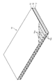
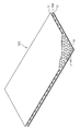
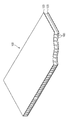
- the interposition member 16 is a member formed in a plate shape having an uneven shape.
- the interposition member 16 is joined to the inward surface of the plate-like member 12 in a state of being sandwiched between the plurality of plate-like members 12.
- the plate member 12 and the interposition member 16 are joined with, for example, an adhesive or a pressure sensitive adhesive. Thereby, the hollow structure according to the uneven
- the weight can be reduced and the material cost can be reduced accordingly.
- the hollow plate member 10 is cut into a predetermined shape or formed into a predetermined shape easy folding line 119 (described later) by providing a cutting blade and a projection or blade for forming the easy folding line 119 on the surface of a pair of rollers. This can be done easily and continuously by sandwiching the hollow plate 10 between a pair of rollers.
- a pair of belt-like plate members 12 are continuously supplied along the predetermined conveying path to the downstream side of the pair of rollers, and the interposition member 16 is interposed between the pair of belt-like plate members 12. Are sequentially inserted and joined with an adhesive or the like. Thereby, the hollow board
- the electromagnetic shielding member 19 is provided in the one main surface of the hollow plate material 10, it can perform electromagnetic shielding with respect to a wire harness.
- the electromagnetic shield member 19 is preferably provided on both surfaces of the hollow plate 10.
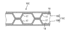
- the hollow plate material includes three or more plate-like members, it is preferable that an intervening member is provided between them. Thereby, the intensity
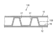
- This hollow plate material 10B is different from the hollow plate material 10 in that an interposed member 16B is used instead of the interposed member 16.
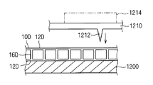
- This hollow plate material 10D is a member formed of a resin material, and includes a plurality (here, two) of plate-like portions 12D and an interposition portion 16D interposed between the plate-like portions 12D, and has a ladder-like cross section. It is formed in the shape to have.
- the wire harness 30 includes at least one electric wire.
- the wire harness 30 is configured by bundling a plurality of electric wires.
- the plurality of electric wires are arranged along a wiring route in the vehicle.
- a connector or the like is connected to the end of the wire harness 30, and the wire harness 30 is connected to various electric devices in the vehicle via the connector or the like.
- the wire harness 30 electrically interconnects various electric devices in the vehicle.
- the wire harness may be branched in the middle or may not be branched.
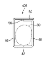
- the bottom 42 is formed in an elongated plate shape.
- the bottom part 42 is formed in a rectangular shape extending straight and having an equal width in the extending direction.
- the bottom part 42 may be bent in the width direction in the middle of the extending direction.
- a lid 50 is provided at the tip of one side wall 46.
- the lid portion 50 extends from one tip portion of the pair of side wall portions 46 toward the other tip portion, and has a shape capable of closing the elongated opening between the tip portions of the pair of side wall portions 46, 46, that is, It is formed in an elongated plate shape.
- a locking slit 50S is formed at the distal end of the lid 50 along the extending direction of the distal edge.
- locking slits 50 ⁇ / b> S are formed at two positions at a distance from the tip of the lid 50.
- a locking piece 46 a is formed at the tip of the other side wall 46.
- the locking piece 46a which is a partial protrusion piece is formed at intervals along the extending direction of the distal end portion of the one side wall portion 46.
- a method of bending the hollow plate material 10 a method of bending the hollow plate material 10 by hand or by a bending device as described later is assumed.
- a method of pressing the hollow plate material 10 against a mold surface having a target shape while heating is also assumed.
- the hollow plate 10 may be sandwiched between a pair of mold surfaces, or the hollow plate 10 may be pressed against one mold surface by atmospheric pressure, such as vacuum molding or blow molding. Vacuum molding or blow molding has the advantage that the hollow structure of the hollow plate 10 is better maintained.
- the protector 40 is formed of a hollow plate material in which a hollow structure is formed between a plurality of plate-like portions, the protector 40 can be excellent in strength.
- the protector 40 is also lightweight.
- the protector 140 has the same configuration as the protector 40 described in the first embodiment except for the following points.
- the protector 140 includes a bottom portion 42, a pair of side wall portions 46, and a lid portion 50, similar to the protector 40.
- the main differences between the protector 140 and the protector 40 are as follows.
- Such a contact part should just be formed adjacent to the part bent, for example, may be formed in the side wall part side.
- a concave portion 193 in which the wire harness 30 can be disposed is formed at the center in the width direction of the upper end portion of the substrate portion 192.
- the recess 193 is formed in a shape that gradually expands upward.
- a method of manufacturing the wire harness 120 with a protector using the protector assembling jig 180 will be described.
- the wire harness 30 is disposed on the bottom 42 along the extending direction of the bottom 42.
- the hollow plate material is bent along a foldable line 119 between the bottom portion 42 and the pair of side wall portions 46, and the pair of side wall portions 46 rises in an orthogonal posture on both sides of the bottom portion 42.
- the wire harness 30 is accommodated.
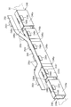
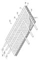
- FIG. 16 is a schematic perspective view showing a wire harness 220 with a protector according to a second modification.
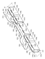
- FIG. 17 is a developed perspective view showing a hollow plate 210 for producing a protector 240 according to a second modification, and
- FIGS. 18 to 21 are explanatory views showing steps for producing a wire harness 220 with a protector.
- the sidewall portions 246, 248 include sidewall portions 246a, 246b, 246c, 246d, 246e or sidewall portions 248a, 248b, 248c, 248d, 248e connected to both sides of the bottom portions 242a, 242b, 242c, 242d, 242e. .
- the protector 340 is constituted by the hollow plate member 10B, an injection mold apparatus or the like for manufacturing a large-sized protector corresponding to the arrangement path of the wire harness 330 is not necessary. For this reason, the protector 340 can be manufactured at low cost.
- a wire member 400 having a magnetic body 402 such as iron attached to the tip is prepared.
- a material made of natural fiber or chemical fiber, a thin resin wire, a thin metal wire, or the like can be used, and it is preferable to use a flexible material as much as possible.
- one end of the wire harness divided portion 330 a is connected to the linear member 400.
- the connection between the wire harness divided portion 330a and the linear member 400 can be performed by connecting the linear member 400 to the wire harness divided portion 330a.
- the other wire harness divided portions 330b and 330c can be accommodated in the hollow plate 10B along the same desired path.
- the wire harness divided portion 330a is disposed between the protrusions 17 of the interposition member 16B, and then the one plate-like member 12 is attached. You may join to the interposition member 16B.
Landscapes
- Engineering & Computer Science (AREA)
- Architecture (AREA)
- Civil Engineering (AREA)
- Structural Engineering (AREA)
- Details Of Indoor Wiring (AREA)
- Protection Of Pipes Against Damage, Friction, And Corrosion (AREA)
Abstract
Le but de la présente invention est de rendre possible que, tout en maintenant un faisceau de fils pour qu'il ait une certaine forme de chemin, un protecteur servant à protéger le faisceau de fils puisse être fabriqué à bas coût, puisse être transporté efficacement, et possède également une excellente résistance. Un faisceau de fils muni d'un protecteur comprend : un protecteur fait d'un matériau en plaque creux dans lequel une structure creuse est formée entre une pluralité de parties du type plaque ; et un faisceau de fils comprenant au moins un fil électrique et logé dans le protecteur. Le protecteur (40) est, par exemple, formé par pliage du matériau en plaque creux de manière à lui donner une forme comprenant une partie inférieure (42) et une paire de parties paroi latérale (46). Selon une variante, le faisceau de fils est, par exemple, logé dans la structure creuse du matériau en plaque creux constituant le protecteur.
Applications Claiming Priority (4)
| Application Number | Priority Date | Filing Date | Title |
|---|---|---|---|
| JP2013160967 | 2013-08-02 | ||
| JP2013-160967 | 2013-08-02 | ||
| JP2013259442A JP6156118B2 (ja) | 2013-08-02 | 2013-12-16 | プロテクタ付ワイヤーハーネス、プロテクタ付ワイヤーハーネスの製造方法、プロテクタ組立用治具 |
| JP2013-259442 | 2013-12-16 |
Publications (1)
| Publication Number | Publication Date |
|---|---|
| WO2015016056A1 true WO2015016056A1 (fr) | 2015-02-05 |
Family
ID=52431596
Family Applications (1)
| Application Number | Title | Priority Date | Filing Date |
|---|---|---|---|
| PCT/JP2014/068757 Ceased WO2015016056A1 (fr) | 2013-08-02 | 2014-07-15 | Faisceau de fils muni d'un protecteur, procédé de fabrication d'un faisceau de fils muni d'un protecteur, bâti d'assemblage de protecteur, et protecteur |
Country Status (2)
| Country | Link |
|---|---|
| JP (1) | JP6156118B2 (fr) |
| WO (1) | WO2015016056A1 (fr) |
Cited By (14)
| Publication number | Priority date | Publication date | Assignee | Title |
|---|---|---|---|---|
| WO2015129428A1 (fr) * | 2014-02-26 | 2015-09-03 | 株式会社オートネットワーク技術研究所 | Élément de blindage électromagnétique |
| WO2016117405A1 (fr) * | 2015-01-19 | 2016-07-28 | 住友電装株式会社 | Structure d'identification de faisceau de câbles |
| WO2016129377A1 (fr) * | 2015-02-09 | 2016-08-18 | 株式会社オートネットワーク技術研究所 | Corps de support de harnais de câbles, harnais de câbles, et élément de protection |
| WO2016133018A1 (fr) * | 2015-02-19 | 2016-08-25 | 住友電装株式会社 | Faisceau de câbles |
| WO2017018166A1 (fr) * | 2015-07-24 | 2017-02-02 | 株式会社オートネットワーク技術研究所 | Enveloppe extérieure de fil électrique, faisceau de câbles, et lame graduée |
| WO2017018164A1 (fr) * | 2015-07-24 | 2017-02-02 | 株式会社オートネットワーク技術研究所 | Enveloppe extérieure de fil électrique, faisceau de câbles, et lame graduée |
| WO2019003704A1 (fr) | 2017-06-30 | 2019-01-03 | 古河電気工業株式会社 | Corps extérieur de fil électrique et faisceau de fils à corps extérieur |
| JP2019122113A (ja) * | 2017-12-28 | 2019-07-22 | 古河電気工業株式会社 | 電線用外装体及び外装体付きワイヤーハーネス |
| CN110214401A (zh) * | 2016-01-28 | 2019-09-06 | 株式会社自动网络技术研究所 | 带有保护器的电线以及带有保护器的电线的配设结构 |
| WO2019191401A1 (fr) * | 2018-03-29 | 2019-10-03 | Molex, Llc | Colonne vertébrale pour la protection et le support d'un faisceau de câbles |
| CN112771743A (zh) * | 2018-09-26 | 2021-05-07 | 古河电气工业株式会社 | 电线用护套及具有护套的线束 |
| US20210375503A1 (en) * | 2019-02-22 | 2021-12-02 | Furukawa Electric Co., Ltd. | Electric wire outer cover and covered wire harness |
| WO2022054434A1 (fr) * | 2020-09-11 | 2022-03-17 | 株式会社オートネットワーク技術研究所 | Composant de nouage et faisceau de câbles |
| JP2023154485A (ja) * | 2022-04-07 | 2023-10-20 | 古河電気工業株式会社 | シールド外装部材、外装部材付ワイヤーハーネス、及びシールド外装部材の製造方法 |
Families Citing this family (5)
| Publication number | Priority date | Publication date | Assignee | Title |
|---|---|---|---|---|
| US11114833B2 (en) * | 2017-12-28 | 2021-09-07 | Furukawa Electric Co., Ltd. | Wire exterior body and exterior-covered wire harness |
| JP6764892B2 (ja) * | 2018-03-12 | 2020-10-07 | 住友電装株式会社 | ハーネスプロテクタおよびワイヤハーネスの配索構造 |
| JP7028731B2 (ja) * | 2018-07-04 | 2022-03-02 | 古河電気工業株式会社 | 電線用外装体及び外装体付きワイヤーハーネス |
| JP7419837B2 (ja) * | 2020-01-27 | 2024-01-23 | 株式会社リコー | 電線束保護部材 |
| JP7382874B2 (ja) * | 2020-03-25 | 2023-11-17 | 古河電気工業株式会社 | 外装部材 |
Citations (10)
| Publication number | Priority date | Publication date | Assignee | Title |
|---|---|---|---|---|
| JPS6235302U (fr) * | 1985-04-09 | 1987-03-02 | ||
| JPH0348320U (fr) * | 1989-09-20 | 1991-05-09 | ||
| JPH03190520A (ja) * | 1989-12-18 | 1991-08-20 | Nitto Denko Corp | 床面配線用巾木並びに床面配線構造 |
| JPH07212936A (ja) * | 1994-01-14 | 1995-08-11 | Sumitomo Wiring Syst Ltd | ワイヤハーネス用成形プロテクタ |
| JPH10285742A (ja) * | 1997-04-07 | 1998-10-23 | Yazaki Corp | カバー付プロテクタ |
| JPH11215640A (ja) * | 1998-01-22 | 1999-08-06 | Yazaki Corp | 長尺部材用プロテクタ |
| JP2005057967A (ja) * | 2003-08-07 | 2005-03-03 | Yazaki Corp | ハーネスプロテクタ |
| JP2010166750A (ja) * | 2009-01-19 | 2010-07-29 | Sumitomo Wiring Syst Ltd | ワイヤハーネス用プロテクタ |
| JP2010259297A (ja) * | 2009-04-28 | 2010-11-11 | Sumitomo Wiring Syst Ltd | ワイヤハーネス・モジュール、該ワイヤハーネス・モジュールの製造方法および車体取付構造 |
| JP2012101502A (ja) * | 2010-11-12 | 2012-05-31 | Seiwa Electric Mfg Co Ltd | 配線ダクトのダクト本体の製造方法及びダクト本体製造装置 |
Family Cites Families (3)
| Publication number | Priority date | Publication date | Assignee | Title |
|---|---|---|---|---|
| JPS6392209A (ja) * | 1986-09-03 | 1988-04-22 | 矢崎総業株式会社 | ケ−ブルの接続方法 |
| JP2004009493A (ja) * | 2002-06-06 | 2004-01-15 | Mamoru Kamo | 板状中空構造体とその製造方法 |
| JP6059975B2 (ja) * | 2012-12-11 | 2017-01-11 | 矢崎総業株式会社 | ワイヤハーネス及びワイヤハーネスの製造方法 |
-
2013
- 2013-12-16 JP JP2013259442A patent/JP6156118B2/ja not_active Expired - Fee Related
-
2014
- 2014-07-15 WO PCT/JP2014/068757 patent/WO2015016056A1/fr not_active Ceased
Patent Citations (10)
| Publication number | Priority date | Publication date | Assignee | Title |
|---|---|---|---|---|
| JPS6235302U (fr) * | 1985-04-09 | 1987-03-02 | ||
| JPH0348320U (fr) * | 1989-09-20 | 1991-05-09 | ||
| JPH03190520A (ja) * | 1989-12-18 | 1991-08-20 | Nitto Denko Corp | 床面配線用巾木並びに床面配線構造 |
| JPH07212936A (ja) * | 1994-01-14 | 1995-08-11 | Sumitomo Wiring Syst Ltd | ワイヤハーネス用成形プロテクタ |
| JPH10285742A (ja) * | 1997-04-07 | 1998-10-23 | Yazaki Corp | カバー付プロテクタ |
| JPH11215640A (ja) * | 1998-01-22 | 1999-08-06 | Yazaki Corp | 長尺部材用プロテクタ |
| JP2005057967A (ja) * | 2003-08-07 | 2005-03-03 | Yazaki Corp | ハーネスプロテクタ |
| JP2010166750A (ja) * | 2009-01-19 | 2010-07-29 | Sumitomo Wiring Syst Ltd | ワイヤハーネス用プロテクタ |
| JP2010259297A (ja) * | 2009-04-28 | 2010-11-11 | Sumitomo Wiring Syst Ltd | ワイヤハーネス・モジュール、該ワイヤハーネス・モジュールの製造方法および車体取付構造 |
| JP2012101502A (ja) * | 2010-11-12 | 2012-05-31 | Seiwa Electric Mfg Co Ltd | 配線ダクトのダクト本体の製造方法及びダクト本体製造装置 |
Cited By (22)
| Publication number | Priority date | Publication date | Assignee | Title |
|---|---|---|---|---|
| WO2015129428A1 (fr) * | 2014-02-26 | 2015-09-03 | 株式会社オートネットワーク技術研究所 | Élément de blindage électromagnétique |
| WO2016117405A1 (fr) * | 2015-01-19 | 2016-07-28 | 住友電装株式会社 | Structure d'identification de faisceau de câbles |
| WO2016129377A1 (fr) * | 2015-02-09 | 2016-08-18 | 株式会社オートネットワーク技術研究所 | Corps de support de harnais de câbles, harnais de câbles, et élément de protection |
| WO2016133018A1 (fr) * | 2015-02-19 | 2016-08-25 | 住友電装株式会社 | Faisceau de câbles |
| WO2017018166A1 (fr) * | 2015-07-24 | 2017-02-02 | 株式会社オートネットワーク技術研究所 | Enveloppe extérieure de fil électrique, faisceau de câbles, et lame graduée |
| WO2017018164A1 (fr) * | 2015-07-24 | 2017-02-02 | 株式会社オートネットワーク技術研究所 | Enveloppe extérieure de fil électrique, faisceau de câbles, et lame graduée |
| CN110214401A (zh) * | 2016-01-28 | 2019-09-06 | 株式会社自动网络技术研究所 | 带有保护器的电线以及带有保护器的电线的配设结构 |
| WO2019003704A1 (fr) | 2017-06-30 | 2019-01-03 | 古河電気工業株式会社 | Corps extérieur de fil électrique et faisceau de fils à corps extérieur |
| US11189397B2 (en) | 2017-06-30 | 2021-11-30 | Furukawa Electric Co., Ltd. | Outer cover body for electrical wires and outer-cover-body-attached wire harness |
| JP2019122113A (ja) * | 2017-12-28 | 2019-07-22 | 古河電気工業株式会社 | 電線用外装体及び外装体付きワイヤーハーネス |
| CN111919353A (zh) * | 2018-03-29 | 2020-11-10 | 莫列斯有限公司 | 保护和支撑线缆线束的脊梁 |
| WO2019191401A1 (fr) * | 2018-03-29 | 2019-10-03 | Molex, Llc | Colonne vertébrale pour la protection et le support d'un faisceau de câbles |
| CN111919353B (zh) * | 2018-03-29 | 2021-12-28 | 莫列斯有限公司 | 保护和支撑线缆线束的脊梁 |
| US11283248B2 (en) | 2018-03-29 | 2022-03-22 | Molex, Llc | Spine for protecting and supporting a cable harness |
| CN112771743A (zh) * | 2018-09-26 | 2021-05-07 | 古河电气工业株式会社 | 电线用护套及具有护套的线束 |
| US11738700B2 (en) * | 2018-09-26 | 2023-08-29 | Furukawa Electric Co., Ltd. | Wire exterior body and exterior-covered wire harness |
| US20210375503A1 (en) * | 2019-02-22 | 2021-12-02 | Furukawa Electric Co., Ltd. | Electric wire outer cover and covered wire harness |
| JPWO2020170559A1 (ja) * | 2019-02-22 | 2021-12-23 | 古河電気工業株式会社 | 電線用外装体及び外装体付きワイヤーハーネス |
| JP7328318B2 (ja) | 2019-02-22 | 2023-08-16 | 古河電気工業株式会社 | 電線用外装体及び外装体付きワイヤーハーネス |
| US11869683B2 (en) * | 2019-02-22 | 2024-01-09 | Furukawa Electric Co., Ltd. | Electric wire outer cover and covered wire harness |
| WO2022054434A1 (fr) * | 2020-09-11 | 2022-03-17 | 株式会社オートネットワーク技術研究所 | Composant de nouage et faisceau de câbles |
| JP2023154485A (ja) * | 2022-04-07 | 2023-10-20 | 古河電気工業株式会社 | シールド外装部材、外装部材付ワイヤーハーネス、及びシールド外装部材の製造方法 |
Also Published As
| Publication number | Publication date |
|---|---|
| JP2015047057A (ja) | 2015-03-12 |
| JP6156118B2 (ja) | 2017-07-05 |
Similar Documents
| Publication | Publication Date | Title |
|---|---|---|
| JP6156118B2 (ja) | プロテクタ付ワイヤーハーネス、プロテクタ付ワイヤーハーネスの製造方法、プロテクタ組立用治具 | |
| JP5644542B2 (ja) | ワイヤハーネス | |
| JP6171914B2 (ja) | ワイヤーハーネスの製造方法及びワイヤーハーネス | |
| JP2015162915A (ja) | 電線付きモジュール | |
| JP6996639B2 (ja) | 配線部材及び配線部材の製造方法 | |
| JP6065828B2 (ja) | プロテクター及び電線モジュール | |
| JP2015053748A (ja) | ワイヤハーネス用の外装材 | |
| JP6065830B2 (ja) | プロテクタ、電線モジュール、およびプロテクタの製造方法 | |
| US20180170287A1 (en) | Wire module and wire protection member | |
| CN107210093A (zh) | 电线模块 | |
| JP5449084B2 (ja) | 板状体の梱包材 | |
| JP6065829B2 (ja) | プロテクター及び電線モジュール | |
| JP2017094730A (ja) | 中空板材の成形方法 | |
| JP5919661B2 (ja) | 配線具、ワイヤハーネス及びワイヤハーネスの製造方法 | |
| JP7113615B2 (ja) | 包装袋、包装袋の製造方法 | |
| JP2016040969A (ja) | プロテクタ及び電線モジュール | |
| JP2016025763A (ja) | 電線モジュール | |
| JP6168037B2 (ja) | ワイヤハーネス用の外装材 | |
| JP6943757B2 (ja) | 電線用外装体及び外装体付きワイヤーハーネス | |
| JP2014107917A (ja) | ワイヤーハーネス | |
| JP4339088B2 (ja) | 樹脂ボードの端末構造及び端末処理方法 | |
| JP2016119785A (ja) | 保護部材付電線及び保護部材 | |
| JP6857430B1 (ja) | 段ボール構造収納ケース | |
| JP6156269B2 (ja) | 車両電装部品用収容ケース及び電線モジュール | |
| JP2016081823A (ja) | 電線モジュール |
Legal Events
| Date | Code | Title | Description |
|---|---|---|---|
| 121 | Ep: the epo has been informed by wipo that ep was designated in this application |
Ref document number: 14831502 Country of ref document: EP Kind code of ref document: A1 |
|
| NENP | Non-entry into the national phase |
Ref country code: DE |
|
| 122 | Ep: pct application non-entry in european phase |
Ref document number: 14831502 Country of ref document: EP Kind code of ref document: A1 |