WO2015019507A1 - Moteur - Google Patents
Moteur Download PDFInfo
- Publication number
- WO2015019507A1 WO2015019507A1 PCT/JP2013/077291 JP2013077291W WO2015019507A1 WO 2015019507 A1 WO2015019507 A1 WO 2015019507A1 JP 2013077291 W JP2013077291 W JP 2013077291W WO 2015019507 A1 WO2015019507 A1 WO 2015019507A1
- Authority
- WO
- WIPO (PCT)
- Prior art keywords
- stator
- rotor
- electric motor
- bearing
- housing
- Prior art date
- Legal status (The legal status is an assumption and is not a legal conclusion. Google has not performed a legal analysis and makes no representation as to the accuracy of the status listed.)
- Ceased
Links
Images
Classifications
-
- B—PERFORMING OPERATIONS; TRANSPORTING
- B60—VEHICLES IN GENERAL
- B60L—PROPULSION OF ELECTRICALLY-PROPELLED VEHICLES; SUPPLYING ELECTRIC POWER FOR AUXILIARY EQUIPMENT OF ELECTRICALLY-PROPELLED VEHICLES; ELECTRODYNAMIC BRAKE SYSTEMS FOR VEHICLES IN GENERAL; MAGNETIC SUSPENSION OR LEVITATION FOR VEHICLES; MONITORING OPERATING VARIABLES OF ELECTRICALLY-PROPELLED VEHICLES; ELECTRIC SAFETY DEVICES FOR ELECTRICALLY-PROPELLED VEHICLES
- B60L50/00—Electric propulsion with power supplied within the vehicle
- B60L50/10—Electric propulsion with power supplied within the vehicle using propulsion power supplied by engine-driven generators, e.g. generators driven by combustion engines
- B60L50/13—Electric propulsion with power supplied within the vehicle using propulsion power supplied by engine-driven generators, e.g. generators driven by combustion engines using AC generators and AC motors
-
- H—ELECTRICITY
- H02—GENERATION; CONVERSION OR DISTRIBUTION OF ELECTRIC POWER
- H02K—DYNAMO-ELECTRIC MACHINES
- H02K5/00—Casings; Enclosures; Supports
- H02K5/02—Casings or enclosures characterised by the material thereof
-
- H—ELECTRICITY
- H02—GENERATION; CONVERSION OR DISTRIBUTION OF ELECTRIC POWER
- H02K—DYNAMO-ELECTRIC MACHINES
- H02K1/00—Details of the magnetic circuit
- H02K1/06—Details of the magnetic circuit characterised by the shape, form or construction
- H02K1/22—Rotating parts of the magnetic circuit
- H02K1/27—Rotor cores with permanent magnets
- H02K1/2706—Inner rotors
- H02K1/272—Inner rotors the magnetisation axis of the magnets being perpendicular to the rotor axis
- H02K1/274—Inner rotors the magnetisation axis of the magnets being perpendicular to the rotor axis the rotor consisting of two or more circumferentially positioned magnets
-
- H—ELECTRICITY
- H02—GENERATION; CONVERSION OR DISTRIBUTION OF ELECTRIC POWER
- H02K—DYNAMO-ELECTRIC MACHINES
- H02K11/00—Structural association of dynamo-electric machines with electric components or with devices for shielding, monitoring or protection
- H02K11/0094—Structural association with other electrical or electronic devices
-
- H—ELECTRICITY
- H02—GENERATION; CONVERSION OR DISTRIBUTION OF ELECTRIC POWER
- H02K—DYNAMO-ELECTRIC MACHINES
- H02K3/00—Details of windings
- H02K3/04—Windings characterised by the conductor shape, form or construction, e.g. with bar conductors
- H02K3/12—Windings characterised by the conductor shape, form or construction, e.g. with bar conductors arranged in slots
-
- H—ELECTRICITY
- H02—GENERATION; CONVERSION OR DISTRIBUTION OF ELECTRIC POWER
- H02K—DYNAMO-ELECTRIC MACHINES
- H02K3/00—Details of windings
- H02K3/04—Windings characterised by the conductor shape, form or construction, e.g. with bar conductors
- H02K3/28—Layout of windings or of connections between windings
-
- H—ELECTRICITY
- H02—GENERATION; CONVERSION OR DISTRIBUTION OF ELECTRIC POWER
- H02K—DYNAMO-ELECTRIC MACHINES
- H02K5/00—Casings; Enclosures; Supports
- H02K5/04—Casings or enclosures characterised by the shape, form or construction thereof
- H02K5/16—Means for supporting bearings, e.g. insulating supports or means for fitting bearings in the bearing-shields
- H02K5/161—Means for supporting bearings, e.g. insulating supports or means for fitting bearings in the bearing-shields radially supporting the rotary shaft at both ends of the rotor
-
- H—ELECTRICITY
- H02—GENERATION; CONVERSION OR DISTRIBUTION OF ELECTRIC POWER
- H02K—DYNAMO-ELECTRIC MACHINES
- H02K7/00—Arrangements for handling mechanical energy structurally associated with dynamo-electric machines, e.g. structural association with mechanical driving motors or auxiliary dynamo-electric machines
- H02K7/006—Structural association of a motor or generator with the drive train of a motor vehicle
-
- H—ELECTRICITY
- H02—GENERATION; CONVERSION OR DISTRIBUTION OF ELECTRIC POWER
- H02P—CONTROL OR REGULATION OF ELECTRIC MOTORS, ELECTRIC GENERATORS OR DYNAMO-ELECTRIC CONVERTERS; CONTROLLING TRANSFORMERS, REACTORS OR CHOKE COILS
- H02P25/00—Arrangements or methods for the control of AC motors characterised by the kind of AC motor or by structural details
- H02P25/16—Arrangements or methods for the control of AC motors characterised by the kind of AC motor or by structural details characterised by the circuit arrangement or by the kind of wiring
- H02P25/22—Multiple windings; Windings for more than three phases
-
- H—ELECTRICITY
- H02—GENERATION; CONVERSION OR DISTRIBUTION OF ELECTRIC POWER
- H02P—CONTROL OR REGULATION OF ELECTRIC MOTORS, ELECTRIC GENERATORS OR DYNAMO-ELECTRIC CONVERTERS; CONTROLLING TRANSFORMERS, REACTORS OR CHOKE COILS
- H02P27/00—Arrangements or methods for the control of AC motors characterised by the kind of supply voltage
- H02P27/04—Arrangements or methods for the control of AC motors characterised by the kind of supply voltage using variable-frequency supply voltage, e.g. inverter or converter supply voltage
- H02P27/06—Arrangements or methods for the control of AC motors characterised by the kind of supply voltage using variable-frequency supply voltage, e.g. inverter or converter supply voltage using DC to AC converters or inverters
-
- B—PERFORMING OPERATIONS; TRANSPORTING
- B60—VEHICLES IN GENERAL
- B60L—PROPULSION OF ELECTRICALLY-PROPELLED VEHICLES; SUPPLYING ELECTRIC POWER FOR AUXILIARY EQUIPMENT OF ELECTRICALLY-PROPELLED VEHICLES; ELECTRODYNAMIC BRAKE SYSTEMS FOR VEHICLES IN GENERAL; MAGNETIC SUSPENSION OR LEVITATION FOR VEHICLES; MONITORING OPERATING VARIABLES OF ELECTRICALLY-PROPELLED VEHICLES; ELECTRIC SAFETY DEVICES FOR ELECTRICALLY-PROPELLED VEHICLES
- B60L2220/00—Electrical machine types; Structures or applications thereof
- B60L2220/50—Structural details of electrical machines
- B60L2220/54—Windings for different functions
-
- B—PERFORMING OPERATIONS; TRANSPORTING
- B60—VEHICLES IN GENERAL
- B60L—PROPULSION OF ELECTRICALLY-PROPELLED VEHICLES; SUPPLYING ELECTRIC POWER FOR AUXILIARY EQUIPMENT OF ELECTRICALLY-PROPELLED VEHICLES; ELECTRODYNAMIC BRAKE SYSTEMS FOR VEHICLES IN GENERAL; MAGNETIC SUSPENSION OR LEVITATION FOR VEHICLES; MONITORING OPERATING VARIABLES OF ELECTRICALLY-PROPELLED VEHICLES; ELECTRIC SAFETY DEVICES FOR ELECTRICALLY-PROPELLED VEHICLES
- B60L2270/00—Problem solutions or means not otherwise provided for
- B60L2270/10—Emission reduction
- B60L2270/14—Emission reduction of noise
- B60L2270/145—Structure borne vibrations
-
- H—ELECTRICITY
- H02—GENERATION; CONVERSION OR DISTRIBUTION OF ELECTRIC POWER
- H02K—DYNAMO-ELECTRIC MACHINES
- H02K2213/00—Specific aspects, not otherwise provided for and not covered by codes H02K2201/00 - H02K2211/00
- H02K2213/03—Machines characterised by numerical values, ranges, mathematical expressions or similar information
-
- Y—GENERAL TAGGING OF NEW TECHNOLOGICAL DEVELOPMENTS; GENERAL TAGGING OF CROSS-SECTIONAL TECHNOLOGIES SPANNING OVER SEVERAL SECTIONS OF THE IPC; TECHNICAL SUBJECTS COVERED BY FORMER USPC CROSS-REFERENCE ART COLLECTIONS [XRACs] AND DIGESTS
- Y02—TECHNOLOGIES OR APPLICATIONS FOR MITIGATION OR ADAPTATION AGAINST CLIMATE CHANGE
- Y02T—CLIMATE CHANGE MITIGATION TECHNOLOGIES RELATED TO TRANSPORTATION
- Y02T10/00—Road transport of goods or passengers
- Y02T10/60—Other road transportation technologies with climate change mitigation effect
- Y02T10/64—Electric machine technologies in electromobility
-
- Y—GENERAL TAGGING OF NEW TECHNOLOGICAL DEVELOPMENTS; GENERAL TAGGING OF CROSS-SECTIONAL TECHNOLOGIES SPANNING OVER SEVERAL SECTIONS OF THE IPC; TECHNICAL SUBJECTS COVERED BY FORMER USPC CROSS-REFERENCE ART COLLECTIONS [XRACs] AND DIGESTS
- Y02—TECHNOLOGIES OR APPLICATIONS FOR MITIGATION OR ADAPTATION AGAINST CLIMATE CHANGE
- Y02T—CLIMATE CHANGE MITIGATION TECHNOLOGIES RELATED TO TRANSPORTATION
- Y02T10/00—Road transport of goods or passengers
- Y02T10/60—Other road transportation technologies with climate change mitigation effect
- Y02T10/70—Energy storage systems for electromobility, e.g. batteries
-
- Y—GENERAL TAGGING OF NEW TECHNOLOGICAL DEVELOPMENTS; GENERAL TAGGING OF CROSS-SECTIONAL TECHNOLOGIES SPANNING OVER SEVERAL SECTIONS OF THE IPC; TECHNICAL SUBJECTS COVERED BY FORMER USPC CROSS-REFERENCE ART COLLECTIONS [XRACs] AND DIGESTS
- Y02—TECHNOLOGIES OR APPLICATIONS FOR MITIGATION OR ADAPTATION AGAINST CLIMATE CHANGE
- Y02T—CLIMATE CHANGE MITIGATION TECHNOLOGIES RELATED TO TRANSPORTATION
- Y02T10/00—Road transport of goods or passengers
- Y02T10/60—Other road transportation technologies with climate change mitigation effect
- Y02T10/7072—Electromobility specific charging systems or methods for batteries, ultracapacitors, supercapacitors or double-layer capacitors
Definitions
- the present invention relates to an electric motor connected between an internal combustion engine and a transmission.
- a high permeability part is provided in a part of the shaft so that axial current does not flow to the bearing (see, for example, Patent Document 1).
- an insulating ring is fitted to the bearing outer ring to electrically insulate the bearing from deterioration due to shaft current (see, for example, Patent Document 2).
- a part of the shaft is made of resin (for example, see Patent Document 3).
- the stator is covered with resin and insulated outside the stator (see, for example, Patent Document 3).
- stator is covered with resin and insulated on the outside of the stator, it is necessary to hold heavy objects such as an internal combustion engine and transmission, and in addition, it must withstand the vibration of the internal combustion engine, There was also a problem of lack.
- a loop composed of a conductor such as a bearing, a housing, a bearing, and a rotating shaft is formed from the rotating shaft, and is linked to the loop.
- the bearing is considered to be an insulator if an oil film made of lubricant oil or grease is formed, but current flows when the oil film becomes thin due to the vibration of the internal combustion engine and the radial force applied to the shaft. When cut off, sparks are generated and electric corrosion occurs on the bearing surface.
- the present invention has been made to solve the above-described problems, and an object of the present invention is to provide a highly reliable electric motor that can reduce axial current with an inexpensive structure.
- An electric motor according to the present invention is an electric motor that is provided between an internal combustion engine and a transmission and is housed in a housing that connects the internal combustion engine and the transmission. ),
- the number of teeth of the stator is 12n (n is a natural number)
- the rotor's rotating shaft, the bearing that supports the rotating shaft, and the housing are made of a conductor and include the rotating shaft, the bearing, and the housing. And having a conductor circuit interlinking with the stator.
- the shaft current can be reduced with an inexpensive structure, and an electric motor having excellent reliability can be obtained.
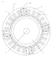
- FIG. 1 is a sectional view of a stator and a rotor of an electric motor according to Embodiment 1 of the present invention
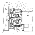
- FIG. 2 is a side sectional view of the electric motor
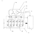
- FIG. 3 is a drive circuit diagram of the electric motor
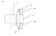
- FIG. It is the schematic of the opening part of the stator winding
- the rotor 1 of the electric motor 100 has a rotating shaft 2 at the center and a magnetic pole 3 to which a permanent magnet is attached at the outer periphery.
- a stator 4 is disposed around the rotor 1 while maintaining a gap.
- the stator 4 is provided with teeth 5 so as to face the magnetic pole 3, and windings 6 are concentrated and wound individually on each of the teeth 5.
- one end of the rotating shaft 2 of the rotor 1 of the electric motor 100 is held by the housing 8 with a bearing 7 a and fixed to the crankshaft 10 of the internal combustion engine 200 via the clutch 9. Is held by the bearing 7c of the internal combustion engine 200.
- the other end of the rotating shaft 2 is held in the housing 8 by a bearing 7b and connected to a transmission (including a speed reducer) 300.
- the housing 8 of the electric motor 100 holds the stator 4 and is fixed to the case 200a of the internal combustion engine 200 at one end surface and fixed to the case 300a of the transmission 300 at the other end surface.
- the rotating shaft 2 is made of iron and has electrical conductivity.
- the rotating shaft 2 is rotatably held at one end in the rotating shaft direction by a conductive bearing 7a via a conductive frame 11a on a conductive housing 8, and the other end in the rotating shaft direction is conductive.
- the bearing 7b has a conductive frame 11b and is rotatably held by the conductive housing 8.
- the crankshaft 10 is made of iron and has electrical conductivity.
- the bearing 7c of the internal combustion engine 200 is a slide bearing and has electrical conductivity.
- the case 200a of the internal combustion engine 200 is made of iron and has electrical conductivity.
- the case 300a of the transmission 300 is made of aluminum and has conductivity.
- the case 300a of the transmission 300 holds the transmission shaft with a ball bearing (not shown).
- the ball bearing and transmission shaft are made of iron and have electrical conductivity.
- the transmission shaft is coupled to the rotating shaft 2 by a spline.
- a conductor circuit is formed that passes through the rotary shaft 2, the bearings 7 a and 7 b, and the housing 8, all of which are conductive, and this conductor circuit is linked to the annular stator 4.
- the conductor circuit is also formed through a conductor such as an internal combustion engine, a bearing of the internal combustion engine, or a case of the internal combustion engine.
- a conductor circuit is formed through conductors such as a transmission, a bearing of the transmission, and a case of the transmission. Therefore, if the bearing is to be insulated, it is necessary to insulate the bearing in the internal combustion engine or the transmission.
- the circumferential magnetic flux of the stator generates a circumferential magnetic flux in the opposite direction at the symmetrical position.
- the magnetic flux in the child circumferential direction becomes zero and no electromotive force is generated in the conductor circuit. Therefore, no current flows through the bearing, and the life of the bearing can be improved.
- the number of magnetic poles of the rotor 1 is 10n (n is a natural number), and the number of teeth of the stator 4 is 12n (n is a natural number).
- the rotor magnetic pole 3 has 20 poles and the stator teeth 5 have 24 teeth.
- the teeth 5 of the stator 4 are wound in the order of U1, U2, V1, V2, W1, W2 from the first tooth.
- U1, V1, and W1 are first three-phase windings
- U2, V2, and W2 are second three-phase windings.
- the first three-phase winding and the second three-phase winding constituting the stator winding are different in electrical angle by 30 degrees.
- FIG. 1 shows the flow of U-phase magnetic flux.
- the number of magnetic poles of the rotor and the number of teeth of the stator are 10:12
- the flow of the circumferential magnetic flux in the core back portions 4a of “U1, U2” and “U1a, U2a” is in the opposite direction. No circumferential magnetic flux is generated as a whole.
- the first three-phase winding 13a is connected to the first three-phase inverter 14a
- the second three-phase winding 13b is connected to the second three-phase inverter 14b.
- the first three-phase inverter 14a and the second three-phase inverter 14b are out of phase by 30 degrees, and a current flows in accordance with the phase of the electromotive force generated by the magnetic poles of the rotor. Thereby, operation with a small torque ripple can be performed.
- the cogging torque is very small with a period of electrical angle 2 ⁇ / 12. If there is torque fluctuation, a large load is applied to the bearing, the oil film becomes small, and the shaft current easily flows. However, according to the present embodiment, the torque ripple is small, so that the oil film of the bearing can be held.
- the shaft current can be reduced by the oil film even if the shaft voltage is generated due to machining accuracy.
- the electric motor 100 is driven and controlled by the control circuit 17 on the basis of detection values from the current sensor 15 that detects the current of the inverter 14 and the rotation sensor 16 that detects the rotation speed of the rotor 1.
- the teeth 5 of the stator 4 are wound in the order of U1, U2, V1, V2, W1, W2 from the first tooth, U1 and U2, V1 and V2. , W1 and W2 are connected in series with the winding direction reversed. (10 poles, 12 slots, single 3-phase connection) Even in this configuration, the circumferential magnetic flux of the stator 4 generates the reverse magnetic flux at the symmetrical position, and these are canceled out. As a result, the stator circumferential magnetic flux becomes zero, and an electromotive force is generated in the above-described conductor circuit. Therefore, no current flows through the bearing, and the life of the bearing can be improved. Further, in this configuration, since only one three-phase inverter is required, the configuration is simplified.
- the first connection plate 18a which is the first connection part constituting the connection part for connecting the first three-phase windings 13a in parallel, is the axial internal combustion engine side of the stator 4.
- connection point between the lead-out portion 19 and the connection plates 18a and 18b is not close in the circumferential direction, and the connection work by welding becomes easy.
- connection plates 18a and 18b are distributed to two locations, the connection plates 18a and 18b can be made small, and the axial dimension of the electric motor sandwiched between the (narrow) internal combustion engine and the transmission that has a strict installation space can be reduced. Can do.
- the connection board 18a, 18b can be reduced in size.
- the size can be minimized in a sandwich type hybrid vehicle in which dimensional constraints are severe.
- connection portions are separated (not close to each other), and it is easy to weld, for example, by welding. Further, if the connection plates 18a and 18b are provided on the outer side in the radial direction of the winding termination portion 6a, the number of places where the connection plates 18a and 18b and the winding termination portion 6a overlap (both sides) increases. The part which protrudes from 6a decreases.
- the present invention is not limited to the above-described embodiment, and the embodiment can be appropriately modified or omitted within the scope of the invention.
Landscapes
- Engineering & Computer Science (AREA)
- Power Engineering (AREA)
- Transportation (AREA)
- Mechanical Engineering (AREA)
- Connection Of Motors, Electrical Generators, Mechanical Devices, And The Like (AREA)
- Motor Or Generator Frames (AREA)
- Permanent Magnet Type Synchronous Machine (AREA)
Abstract
Priority Applications (4)
| Application Number | Priority Date | Filing Date | Title |
|---|---|---|---|
| JP2015530655A JP5936778B2 (ja) | 2013-08-09 | 2013-10-08 | 電動機 |
| US14/898,201 US10305342B2 (en) | 2013-08-09 | 2013-10-08 | Motor |
| DE112013007325.0T DE112013007325T5 (de) | 2013-08-09 | 2013-10-08 | Motor |
| CN201380078782.4A CN105453389B (zh) | 2013-08-09 | 2013-10-08 | 电动机 |
Applications Claiming Priority (2)
| Application Number | Priority Date | Filing Date | Title |
|---|---|---|---|
| JP2013165948 | 2013-08-09 | ||
| JP2013-165948 | 2013-08-09 |
Publications (1)
| Publication Number | Publication Date |
|---|---|
| WO2015019507A1 true WO2015019507A1 (fr) | 2015-02-12 |
Family
ID=52460873
Family Applications (1)
| Application Number | Title | Priority Date | Filing Date |
|---|---|---|---|
| PCT/JP2013/077291 Ceased WO2015019507A1 (fr) | 2013-08-09 | 2013-10-08 | Moteur |
Country Status (5)
| Country | Link |
|---|---|
| US (1) | US10305342B2 (fr) |
| JP (1) | JP5936778B2 (fr) |
| CN (1) | CN105453389B (fr) |
| DE (1) | DE112013007325T5 (fr) |
| WO (1) | WO2015019507A1 (fr) |
Cited By (1)
| Publication number | Priority date | Publication date | Assignee | Title |
|---|---|---|---|---|
| WO2017064756A1 (fr) * | 2015-10-13 | 2017-04-20 | 三菱電機株式会社 | Dispositif de commande de machine rotative à courant alternatif et dispositif de direction assistée électrique comportant ce dernier |
Families Citing this family (3)
| Publication number | Priority date | Publication date | Assignee | Title |
|---|---|---|---|---|
| DE102017213022B4 (de) * | 2017-07-28 | 2020-12-10 | Bayerische Motoren Werke Aktiengesellschaft | Vorrichtung zum reduzieren von wellenströmen bei einer elektrischen maschine |
| DE102018006915A1 (de) * | 2018-08-30 | 2020-03-05 | eMoSys GmbH | Permanenterregte elektrische Maschine |
| BR112023017875A2 (pt) | 2021-03-05 | 2023-10-10 | Tau Motors Inc | Transferência de potência sem fio dentro de uma máquina elétrica com enrolamentos de rotor ativamente retificados |
Citations (2)
| Publication number | Priority date | Publication date | Assignee | Title |
|---|---|---|---|---|
| JPH0595190U (ja) * | 1992-05-19 | 1993-12-24 | 株式会社三協精機製作所 | 電動機 |
| JP2010221775A (ja) * | 2009-03-23 | 2010-10-07 | Aisin Ai Co Ltd | ハイブリッド車用動力伝達装置 |
Family Cites Families (12)
| Publication number | Priority date | Publication date | Assignee | Title |
|---|---|---|---|---|
| ATE132670T1 (de) * | 1990-10-09 | 1996-01-15 | Stridsberg Licensing Ab | Ein elektrischer leistungsantrieb für fahrzeuge |
| JPH10322960A (ja) * | 1997-05-14 | 1998-12-04 | Hitachi Ltd | 電動機 |
| US6348751B1 (en) * | 1997-12-12 | 2002-02-19 | New Generation Motors Corporation | Electric motor with active hysteresis-based control of winding currents and/or having an efficient stator winding arrangement and/or adjustable air gap |
| JP4181380B2 (ja) * | 2002-11-01 | 2008-11-12 | 三菱電機株式会社 | 回転角度検出装置および回転電機 |
| JP4425045B2 (ja) * | 2004-04-14 | 2010-03-03 | 三菱電機株式会社 | レゾルバ |
| CN1588759A (zh) * | 2004-08-23 | 2005-03-02 | 上海海事大学 | 一种双三相永磁同步电机 |
| JP2006211862A (ja) | 2005-01-31 | 2006-08-10 | Yaskawa Electric Corp | 電動機 |
| SI22189A (sl) * | 2005-12-29 | 2007-06-30 | Tomaz Katrasnik | Motorgenerator uporaben kot generatr elektricnegatoka, zaganjalnik motorjev z notranjm zgorevanjemter primarni pogonski stroj |
| JP4894493B2 (ja) | 2006-12-11 | 2012-03-14 | 三菱電機株式会社 | 絶縁リング及び回転電機 |
| JP5230694B2 (ja) | 2010-07-06 | 2013-07-10 | 三菱電機株式会社 | 電動機の回転子及び電動機及び空気調和機 |
| CN101951099A (zh) * | 2010-08-25 | 2011-01-19 | 哈尔滨工业大学 | 高性能直流输出永磁发电机系统 |
| JP5274539B2 (ja) | 2010-11-29 | 2013-08-28 | 三菱電機株式会社 | 電動機及び送風機 |
-
2013
- 2013-10-08 WO PCT/JP2013/077291 patent/WO2015019507A1/fr not_active Ceased
- 2013-10-08 DE DE112013007325.0T patent/DE112013007325T5/de active Pending
- 2013-10-08 US US14/898,201 patent/US10305342B2/en active Active
- 2013-10-08 CN CN201380078782.4A patent/CN105453389B/zh active Active
- 2013-10-08 JP JP2015530655A patent/JP5936778B2/ja active Active
Patent Citations (2)
| Publication number | Priority date | Publication date | Assignee | Title |
|---|---|---|---|---|
| JPH0595190U (ja) * | 1992-05-19 | 1993-12-24 | 株式会社三協精機製作所 | 電動機 |
| JP2010221775A (ja) * | 2009-03-23 | 2010-10-07 | Aisin Ai Co Ltd | ハイブリッド車用動力伝達装置 |
Cited By (3)
| Publication number | Priority date | Publication date | Assignee | Title |
|---|---|---|---|---|
| WO2017064756A1 (fr) * | 2015-10-13 | 2017-04-20 | 三菱電機株式会社 | Dispositif de commande de machine rotative à courant alternatif et dispositif de direction assistée électrique comportant ce dernier |
| JPWO2017064756A1 (ja) * | 2015-10-13 | 2017-11-30 | 三菱電機株式会社 | 交流回転機の制御装置及びそれを備えた電動パワーステアリング装置 |
| US10432129B2 (en) | 2015-10-13 | 2019-10-01 | Mitsubishi Electric Corporation | AC rotary machine control device and electric power steering device |
Also Published As
| Publication number | Publication date |
|---|---|
| DE112013007325T5 (de) | 2016-05-25 |
| US20160126797A1 (en) | 2016-05-05 |
| US10305342B2 (en) | 2019-05-28 |
| JPWO2015019507A1 (ja) | 2017-03-02 |
| JP5936778B2 (ja) | 2016-06-22 |
| CN105453389B (zh) | 2018-11-23 |
| CN105453389A (zh) | 2016-03-30 |
Similar Documents
| Publication | Publication Date | Title |
|---|---|---|
| JP7095731B2 (ja) | 回転電機 | |
| JP4440275B2 (ja) | 三相回転電機 | |
| US7038348B2 (en) | Dynamo electric machine | |
| EP3062426A1 (fr) | Moteur sans balais monophasé | |
| JP2014054094A (ja) | モータ駆動システム | |
| JP7095550B2 (ja) | 回転電機の制御装置及び回転電機の制御方法 | |
| CN102624108B (zh) | 轴向间隙型电动机的定子及轴向间隙型电动机 | |
| US10637305B2 (en) | Double stator-type rotary machine | |
| JP2014155373A (ja) | マルチギャップ型回転電機 | |
| JPWO2014020756A1 (ja) | 回転電機 | |
| JP5936778B2 (ja) | 電動機 | |
| JP6569396B2 (ja) | 回転電機 | |
| JP2015056921A (ja) | 磁気変調モータ及び磁気遊星ギア | |
| JP2005124378A (ja) | リング状の固定子コイルを有する誘導電動機 | |
| JP2017050942A (ja) | 回転電機 | |
| JP6451990B2 (ja) | 回転電機 | |
| KR101393209B1 (ko) | Bldc 듀얼모터장치 | |
| JP2014138491A (ja) | 回転電機システム | |
| JP2005130685A (ja) | リング状の固定子コイルを有する永久磁石型電動機 | |
| JP2008022667A (ja) | 多重巻線交流モータ | |
| JPWO2015199105A1 (ja) | 回転電機 | |
| JP2015056920A (ja) | 磁気変調モータ及び磁気遊星ギア | |
| JP2013021875A (ja) | 回転電機 | |
| JP2011211881A (ja) | リラクタンスモータ | |
| JP2005341782A (ja) | リング状の固定子コイルを有する電動機 |
Legal Events
| Date | Code | Title | Description |
|---|---|---|---|
| WWE | Wipo information: entry into national phase |
Ref document number: 201380078782.4 Country of ref document: CN |
|
| 121 | Ep: the epo has been informed by wipo that ep was designated in this application |
Ref document number: 13890919 Country of ref document: EP Kind code of ref document: A1 |
|
| ENP | Entry into the national phase |
Ref document number: 2015530655 Country of ref document: JP Kind code of ref document: A |
|
| WWE | Wipo information: entry into national phase |
Ref document number: 14898201 Country of ref document: US |
|
| WWE | Wipo information: entry into national phase |
Ref document number: 112013007325 Country of ref document: DE |
|
| 122 | Ep: pct application non-entry in european phase |
Ref document number: 13890919 Country of ref document: EP Kind code of ref document: A1 |