WO2015019681A1 - 加熱機器の熱効率改善方法及び加熱機器の熱効率改善装置 - Google Patents
加熱機器の熱効率改善方法及び加熱機器の熱効率改善装置 Download PDFInfo
- Publication number
- WO2015019681A1 WO2015019681A1 PCT/JP2014/063849 JP2014063849W WO2015019681A1 WO 2015019681 A1 WO2015019681 A1 WO 2015019681A1 JP 2014063849 W JP2014063849 W JP 2014063849W WO 2015019681 A1 WO2015019681 A1 WO 2015019681A1
- Authority
- WO
- WIPO (PCT)
- Prior art keywords
- thermal efficiency
- improving
- heating device
- inorganic
- oxide
- Prior art date
- Legal status (The legal status is an assumption and is not a legal conclusion. Google has not performed a legal analysis and makes no representation as to the accuracy of the status listed.)
- Ceased
Links
Images


Classifications
-
- F—MECHANICAL ENGINEERING; LIGHTING; HEATING; WEAPONS; BLASTING
- F28—HEAT EXCHANGE IN GENERAL
- F28F—DETAILS OF HEAT-EXCHANGE AND HEAT-TRANSFER APPARATUS, OF GENERAL APPLICATION
- F28F13/00—Arrangements for modifying heat-transfer, e.g. increasing, decreasing
-
- B—PERFORMING OPERATIONS; TRANSPORTING
- B32—LAYERED PRODUCTS
- B32B—LAYERED PRODUCTS, i.e. PRODUCTS BUILT-UP OF STRATA OF FLAT OR NON-FLAT, e.g. CELLULAR OR HONEYCOMB, FORM
- B32B18/00—Layered products essentially comprising ceramics, e.g. refractory products
-
- C—CHEMISTRY; METALLURGY
- C04—CEMENTS; CONCRETE; ARTIFICIAL STONE; CERAMICS; REFRACTORIES
- C04B—LIME, MAGNESIA; SLAG; CEMENTS; COMPOSITIONS THEREOF, e.g. MORTARS, CONCRETE OR LIKE BUILDING MATERIALS; ARTIFICIAL STONE; CERAMICS; REFRACTORIES; TREATMENT OF NATURAL STONE
- C04B35/00—Shaped ceramic products characterised by their composition; Ceramics compositions; Processing powders of inorganic compounds preparatory to the manufacturing of ceramic products
- C04B35/515—Shaped ceramic products characterised by their composition; Ceramics compositions; Processing powders of inorganic compounds preparatory to the manufacturing of ceramic products based on non-oxide ceramics
- C04B35/56—Shaped ceramic products characterised by their composition; Ceramics compositions; Processing powders of inorganic compounds preparatory to the manufacturing of ceramic products based on non-oxide ceramics based on carbides or oxycarbides
- C04B35/565—Shaped ceramic products characterised by their composition; Ceramics compositions; Processing powders of inorganic compounds preparatory to the manufacturing of ceramic products based on non-oxide ceramics based on carbides or oxycarbides based on silicon carbide
- C04B35/571—Shaped ceramic products characterised by their composition; Ceramics compositions; Processing powders of inorganic compounds preparatory to the manufacturing of ceramic products based on non-oxide ceramics based on carbides or oxycarbides based on silicon carbide obtained from Si-containing polymer precursors or organosilicon monomers
-
- C—CHEMISTRY; METALLURGY
- C04—CEMENTS; CONCRETE; ARTIFICIAL STONE; CERAMICS; REFRACTORIES
- C04B—LIME, MAGNESIA; SLAG; CEMENTS; COMPOSITIONS THEREOF, e.g. MORTARS, CONCRETE OR LIKE BUILDING MATERIALS; ARTIFICIAL STONE; CERAMICS; REFRACTORIES; TREATMENT OF NATURAL STONE
- C04B35/00—Shaped ceramic products characterised by their composition; Ceramics compositions; Processing powders of inorganic compounds preparatory to the manufacturing of ceramic products
- C04B35/515—Shaped ceramic products characterised by their composition; Ceramics compositions; Processing powders of inorganic compounds preparatory to the manufacturing of ceramic products based on non-oxide ceramics
- C04B35/56—Shaped ceramic products characterised by their composition; Ceramics compositions; Processing powders of inorganic compounds preparatory to the manufacturing of ceramic products based on non-oxide ceramics based on carbides or oxycarbides
- C04B35/565—Shaped ceramic products characterised by their composition; Ceramics compositions; Processing powders of inorganic compounds preparatory to the manufacturing of ceramic products based on non-oxide ceramics based on carbides or oxycarbides based on silicon carbide
- C04B35/573—Shaped ceramic products characterised by their composition; Ceramics compositions; Processing powders of inorganic compounds preparatory to the manufacturing of ceramic products based on non-oxide ceramics based on carbides or oxycarbides based on silicon carbide obtained by reaction sintering or recrystallisation
-
- C—CHEMISTRY; METALLURGY
- C04—CEMENTS; CONCRETE; ARTIFICIAL STONE; CERAMICS; REFRACTORIES
- C04B—LIME, MAGNESIA; SLAG; CEMENTS; COMPOSITIONS THEREOF, e.g. MORTARS, CONCRETE OR LIKE BUILDING MATERIALS; ARTIFICIAL STONE; CERAMICS; REFRACTORIES; TREATMENT OF NATURAL STONE
- C04B35/00—Shaped ceramic products characterised by their composition; Ceramics compositions; Processing powders of inorganic compounds preparatory to the manufacturing of ceramic products
- C04B35/515—Shaped ceramic products characterised by their composition; Ceramics compositions; Processing powders of inorganic compounds preparatory to the manufacturing of ceramic products based on non-oxide ceramics
- C04B35/58—Shaped ceramic products characterised by their composition; Ceramics compositions; Processing powders of inorganic compounds preparatory to the manufacturing of ceramic products based on non-oxide ceramics based on borides, nitrides, i.e. nitrides, oxynitrides, carbonitrides or oxycarbonitrides or silicides
- C04B35/584—Shaped ceramic products characterised by their composition; Ceramics compositions; Processing powders of inorganic compounds preparatory to the manufacturing of ceramic products based on non-oxide ceramics based on borides, nitrides, i.e. nitrides, oxynitrides, carbonitrides or oxycarbonitrides or silicides based on silicon nitride
- C04B35/589—Shaped ceramic products characterised by their composition; Ceramics compositions; Processing powders of inorganic compounds preparatory to the manufacturing of ceramic products based on non-oxide ceramics based on borides, nitrides, i.e. nitrides, oxynitrides, carbonitrides or oxycarbonitrides or silicides based on silicon nitride obtained from Si-containing polymer precursors or organosilicon monomers
-
- C—CHEMISTRY; METALLURGY
- C04—CEMENTS; CONCRETE; ARTIFICIAL STONE; CERAMICS; REFRACTORIES
- C04B—LIME, MAGNESIA; SLAG; CEMENTS; COMPOSITIONS THEREOF, e.g. MORTARS, CONCRETE OR LIKE BUILDING MATERIALS; ARTIFICIAL STONE; CERAMICS; REFRACTORIES; TREATMENT OF NATURAL STONE
- C04B35/00—Shaped ceramic products characterised by their composition; Ceramics compositions; Processing powders of inorganic compounds preparatory to the manufacturing of ceramic products
- C04B35/515—Shaped ceramic products characterised by their composition; Ceramics compositions; Processing powders of inorganic compounds preparatory to the manufacturing of ceramic products based on non-oxide ceramics
- C04B35/58—Shaped ceramic products characterised by their composition; Ceramics compositions; Processing powders of inorganic compounds preparatory to the manufacturing of ceramic products based on non-oxide ceramics based on borides, nitrides, i.e. nitrides, oxynitrides, carbonitrides or oxycarbonitrides or silicides
- C04B35/584—Shaped ceramic products characterised by their composition; Ceramics compositions; Processing powders of inorganic compounds preparatory to the manufacturing of ceramic products based on non-oxide ceramics based on borides, nitrides, i.e. nitrides, oxynitrides, carbonitrides or oxycarbonitrides or silicides based on silicon nitride
- C04B35/593—Shaped ceramic products characterised by their composition; Ceramics compositions; Processing powders of inorganic compounds preparatory to the manufacturing of ceramic products based on non-oxide ceramics based on borides, nitrides, i.e. nitrides, oxynitrides, carbonitrides or oxycarbonitrides or silicides based on silicon nitride obtained by pressure sintering
-
- C—CHEMISTRY; METALLURGY
- C04—CEMENTS; CONCRETE; ARTIFICIAL STONE; CERAMICS; REFRACTORIES
- C04B—LIME, MAGNESIA; SLAG; CEMENTS; COMPOSITIONS THEREOF, e.g. MORTARS, CONCRETE OR LIKE BUILDING MATERIALS; ARTIFICIAL STONE; CERAMICS; REFRACTORIES; TREATMENT OF NATURAL STONE
- C04B35/00—Shaped ceramic products characterised by their composition; Ceramics compositions; Processing powders of inorganic compounds preparatory to the manufacturing of ceramic products
- C04B35/622—Forming processes; Processing powders of inorganic compounds preparatory to the manufacturing of ceramic products
- C04B35/626—Preparing or treating the powders individually or as batches ; preparing or treating macroscopic reinforcing agents for ceramic products, e.g. fibres; mechanical aspects section B
- C04B35/628—Coating the powders or the macroscopic reinforcing agents
- C04B35/62844—Coating fibres
- C04B35/62847—Coating fibres with oxide ceramics
- C04B35/62849—Silica or silicates
-
- C—CHEMISTRY; METALLURGY
- C04—CEMENTS; CONCRETE; ARTIFICIAL STONE; CERAMICS; REFRACTORIES
- C04B—LIME, MAGNESIA; SLAG; CEMENTS; COMPOSITIONS THEREOF, e.g. MORTARS, CONCRETE OR LIKE BUILDING MATERIALS; ARTIFICIAL STONE; CERAMICS; REFRACTORIES; TREATMENT OF NATURAL STONE
- C04B35/00—Shaped ceramic products characterised by their composition; Ceramics compositions; Processing powders of inorganic compounds preparatory to the manufacturing of ceramic products
- C04B35/622—Forming processes; Processing powders of inorganic compounds preparatory to the manufacturing of ceramic products
- C04B35/626—Preparing or treating the powders individually or as batches ; preparing or treating macroscopic reinforcing agents for ceramic products, e.g. fibres; mechanical aspects section B
- C04B35/628—Coating the powders or the macroscopic reinforcing agents
- C04B35/62844—Coating fibres
- C04B35/62847—Coating fibres with oxide ceramics
- C04B35/62852—Alumina or aluminates
-
- C—CHEMISTRY; METALLURGY
- C04—CEMENTS; CONCRETE; ARTIFICIAL STONE; CERAMICS; REFRACTORIES
- C04B—LIME, MAGNESIA; SLAG; CEMENTS; COMPOSITIONS THEREOF, e.g. MORTARS, CONCRETE OR LIKE BUILDING MATERIALS; ARTIFICIAL STONE; CERAMICS; REFRACTORIES; TREATMENT OF NATURAL STONE
- C04B35/00—Shaped ceramic products characterised by their composition; Ceramics compositions; Processing powders of inorganic compounds preparatory to the manufacturing of ceramic products
- C04B35/622—Forming processes; Processing powders of inorganic compounds preparatory to the manufacturing of ceramic products
- C04B35/626—Preparing or treating the powders individually or as batches ; preparing or treating macroscopic reinforcing agents for ceramic products, e.g. fibres; mechanical aspects section B
- C04B35/628—Coating the powders or the macroscopic reinforcing agents
- C04B35/62844—Coating fibres
- C04B35/62857—Coating fibres with non-oxide ceramics
- C04B35/62865—Nitrides
- C04B35/62868—Boron nitride
-
- C—CHEMISTRY; METALLURGY
- C04—CEMENTS; CONCRETE; ARTIFICIAL STONE; CERAMICS; REFRACTORIES
- C04B—LIME, MAGNESIA; SLAG; CEMENTS; COMPOSITIONS THEREOF, e.g. MORTARS, CONCRETE OR LIKE BUILDING MATERIALS; ARTIFICIAL STONE; CERAMICS; REFRACTORIES; TREATMENT OF NATURAL STONE
- C04B35/00—Shaped ceramic products characterised by their composition; Ceramics compositions; Processing powders of inorganic compounds preparatory to the manufacturing of ceramic products
- C04B35/622—Forming processes; Processing powders of inorganic compounds preparatory to the manufacturing of ceramic products
- C04B35/626—Preparing or treating the powders individually or as batches ; preparing or treating macroscopic reinforcing agents for ceramic products, e.g. fibres; mechanical aspects section B
- C04B35/628—Coating the powders or the macroscopic reinforcing agents
- C04B35/62844—Coating fibres
- C04B35/62857—Coating fibres with non-oxide ceramics
- C04B35/62865—Nitrides
- C04B35/62871—Silicon nitride
-
- C—CHEMISTRY; METALLURGY
- C04—CEMENTS; CONCRETE; ARTIFICIAL STONE; CERAMICS; REFRACTORIES
- C04B—LIME, MAGNESIA; SLAG; CEMENTS; COMPOSITIONS THEREOF, e.g. MORTARS, CONCRETE OR LIKE BUILDING MATERIALS; ARTIFICIAL STONE; CERAMICS; REFRACTORIES; TREATMENT OF NATURAL STONE
- C04B35/00—Shaped ceramic products characterised by their composition; Ceramics compositions; Processing powders of inorganic compounds preparatory to the manufacturing of ceramic products
- C04B35/622—Forming processes; Processing powders of inorganic compounds preparatory to the manufacturing of ceramic products
- C04B35/626—Preparing or treating the powders individually or as batches ; preparing or treating macroscopic reinforcing agents for ceramic products, e.g. fibres; mechanical aspects section B
- C04B35/628—Coating the powders or the macroscopic reinforcing agents
- C04B35/62844—Coating fibres
- C04B35/62857—Coating fibres with non-oxide ceramics
- C04B35/62873—Carbon
-
- C—CHEMISTRY; METALLURGY
- C04—CEMENTS; CONCRETE; ARTIFICIAL STONE; CERAMICS; REFRACTORIES
- C04B—LIME, MAGNESIA; SLAG; CEMENTS; COMPOSITIONS THEREOF, e.g. MORTARS, CONCRETE OR LIKE BUILDING MATERIALS; ARTIFICIAL STONE; CERAMICS; REFRACTORIES; TREATMENT OF NATURAL STONE
- C04B35/00—Shaped ceramic products characterised by their composition; Ceramics compositions; Processing powders of inorganic compounds preparatory to the manufacturing of ceramic products
- C04B35/622—Forming processes; Processing powders of inorganic compounds preparatory to the manufacturing of ceramic products
- C04B35/626—Preparing or treating the powders individually or as batches ; preparing or treating macroscopic reinforcing agents for ceramic products, e.g. fibres; mechanical aspects section B
- C04B35/628—Coating the powders or the macroscopic reinforcing agents
- C04B35/62892—Coating the powders or the macroscopic reinforcing agents with a coating layer consisting of particles
-
- C—CHEMISTRY; METALLURGY
- C04—CEMENTS; CONCRETE; ARTIFICIAL STONE; CERAMICS; REFRACTORIES
- C04B—LIME, MAGNESIA; SLAG; CEMENTS; COMPOSITIONS THEREOF, e.g. MORTARS, CONCRETE OR LIKE BUILDING MATERIALS; ARTIFICIAL STONE; CERAMICS; REFRACTORIES; TREATMENT OF NATURAL STONE
- C04B35/00—Shaped ceramic products characterised by their composition; Ceramics compositions; Processing powders of inorganic compounds preparatory to the manufacturing of ceramic products
- C04B35/622—Forming processes; Processing powders of inorganic compounds preparatory to the manufacturing of ceramic products
- C04B35/626—Preparing or treating the powders individually or as batches ; preparing or treating macroscopic reinforcing agents for ceramic products, e.g. fibres; mechanical aspects section B
- C04B35/628—Coating the powders or the macroscopic reinforcing agents
- C04B35/62894—Coating the powders or the macroscopic reinforcing agents with more than one coating layer
-
- C—CHEMISTRY; METALLURGY
- C04—CEMENTS; CONCRETE; ARTIFICIAL STONE; CERAMICS; REFRACTORIES
- C04B—LIME, MAGNESIA; SLAG; CEMENTS; COMPOSITIONS THEREOF, e.g. MORTARS, CONCRETE OR LIKE BUILDING MATERIALS; ARTIFICIAL STONE; CERAMICS; REFRACTORIES; TREATMENT OF NATURAL STONE
- C04B35/00—Shaped ceramic products characterised by their composition; Ceramics compositions; Processing powders of inorganic compounds preparatory to the manufacturing of ceramic products
- C04B35/71—Ceramic products containing macroscopic reinforcing agents
- C04B35/78—Ceramic products containing macroscopic reinforcing agents containing non-metallic materials
- C04B35/80—Fibres, filaments, whiskers, platelets, or the like
-
- F—MECHANICAL ENGINEERING; LIGHTING; HEATING; WEAPONS; BLASTING
- F27—FURNACES; KILNS; OVENS; RETORTS
- F27D—DETAILS OR ACCESSORIES OF FURNACES, KILNS, OVENS OR RETORTS, IN SO FAR AS THEY ARE OF KINDS OCCURRING IN MORE THAN ONE KIND OF FURNACE
- F27D1/00—Casings; Linings; Walls; Roofs
- F27D1/04—Casings; Linings; Walls; Roofs characterised by the form, e.g. shape of the bricks or blocks used
- F27D1/042—Bricks shaped for use in regenerators
-
- F—MECHANICAL ENGINEERING; LIGHTING; HEATING; WEAPONS; BLASTING
- F27—FURNACES; KILNS; OVENS; RETORTS
- F27D—DETAILS OR ACCESSORIES OF FURNACES, KILNS, OVENS OR RETORTS, IN SO FAR AS THEY ARE OF KINDS OCCURRING IN MORE THAN ONE KIND OF FURNACE
- F27D17/00—Arrangements for using waste heat; Arrangements for using, or disposing of, waste gases
- F27D17/10—Arrangements for using waste heat
-
- F—MECHANICAL ENGINEERING; LIGHTING; HEATING; WEAPONS; BLASTING
- F27—FURNACES; KILNS; OVENS; RETORTS
- F27D—DETAILS OR ACCESSORIES OF FURNACES, KILNS, OVENS OR RETORTS, IN SO FAR AS THEY ARE OF KINDS OCCURRING IN MORE THAN ONE KIND OF FURNACE
- F27D17/00—Arrangements for using waste heat; Arrangements for using, or disposing of, waste gases
- F27D17/30—Arrangements for extraction or collection of waste gases; Hoods therefor
- F27D17/302—Constructional details of ancillary components, e.g. waste gas conduits or seals
-
- C—CHEMISTRY; METALLURGY
- C04—CEMENTS; CONCRETE; ARTIFICIAL STONE; CERAMICS; REFRACTORIES
- C04B—LIME, MAGNESIA; SLAG; CEMENTS; COMPOSITIONS THEREOF, e.g. MORTARS, CONCRETE OR LIKE BUILDING MATERIALS; ARTIFICIAL STONE; CERAMICS; REFRACTORIES; TREATMENT OF NATURAL STONE
- C04B2235/00—Aspects relating to ceramic starting mixtures or sintered ceramic products
- C04B2235/02—Composition of constituents of the starting material or of secondary phases of the final product
- C04B2235/50—Constituents or additives of the starting mixture chosen for their shape or used because of their shape or their physical appearance
- C04B2235/52—Constituents or additives characterised by their shapes
- C04B2235/5208—Fibers
- C04B2235/5216—Inorganic
- C04B2235/522—Oxidic
- C04B2235/5228—Silica and alumina, including aluminosilicates, e.g. mullite
-
- C—CHEMISTRY; METALLURGY
- C04—CEMENTS; CONCRETE; ARTIFICIAL STONE; CERAMICS; REFRACTORIES
- C04B—LIME, MAGNESIA; SLAG; CEMENTS; COMPOSITIONS THEREOF, e.g. MORTARS, CONCRETE OR LIKE BUILDING MATERIALS; ARTIFICIAL STONE; CERAMICS; REFRACTORIES; TREATMENT OF NATURAL STONE
- C04B2235/00—Aspects relating to ceramic starting mixtures or sintered ceramic products
- C04B2235/02—Composition of constituents of the starting material or of secondary phases of the final product
- C04B2235/50—Constituents or additives of the starting mixture chosen for their shape or used because of their shape or their physical appearance
- C04B2235/52—Constituents or additives characterised by their shapes
- C04B2235/5208—Fibers
- C04B2235/5216—Inorganic
- C04B2235/524—Non-oxidic, e.g. borides, carbides, silicides or nitrides
- C04B2235/5244—Silicon carbide
-
- C—CHEMISTRY; METALLURGY
- C04—CEMENTS; CONCRETE; ARTIFICIAL STONE; CERAMICS; REFRACTORIES
- C04B—LIME, MAGNESIA; SLAG; CEMENTS; COMPOSITIONS THEREOF, e.g. MORTARS, CONCRETE OR LIKE BUILDING MATERIALS; ARTIFICIAL STONE; CERAMICS; REFRACTORIES; TREATMENT OF NATURAL STONE
- C04B2235/00—Aspects relating to ceramic starting mixtures or sintered ceramic products
- C04B2235/02—Composition of constituents of the starting material or of secondary phases of the final product
- C04B2235/50—Constituents or additives of the starting mixture chosen for their shape or used because of their shape or their physical appearance
- C04B2235/52—Constituents or additives characterised by their shapes
- C04B2235/5208—Fibers
- C04B2235/5216—Inorganic
- C04B2235/524—Non-oxidic, e.g. borides, carbides, silicides or nitrides
- C04B2235/5248—Carbon, e.g. graphite
-
- C—CHEMISTRY; METALLURGY
- C04—CEMENTS; CONCRETE; ARTIFICIAL STONE; CERAMICS; REFRACTORIES
- C04B—LIME, MAGNESIA; SLAG; CEMENTS; COMPOSITIONS THEREOF, e.g. MORTARS, CONCRETE OR LIKE BUILDING MATERIALS; ARTIFICIAL STONE; CERAMICS; REFRACTORIES; TREATMENT OF NATURAL STONE
- C04B2235/00—Aspects relating to ceramic starting mixtures or sintered ceramic products
- C04B2235/02—Composition of constituents of the starting material or of secondary phases of the final product
- C04B2235/50—Constituents or additives of the starting mixture chosen for their shape or used because of their shape or their physical appearance
- C04B2235/54—Particle size related information
- C04B2235/5418—Particle size related information expressed by the size of the particles or aggregates thereof
- C04B2235/5445—Particle size related information expressed by the size of the particles or aggregates thereof submicron sized, i.e. from 0,1 to 1 micron
-
- C—CHEMISTRY; METALLURGY
- C04—CEMENTS; CONCRETE; ARTIFICIAL STONE; CERAMICS; REFRACTORIES
- C04B—LIME, MAGNESIA; SLAG; CEMENTS; COMPOSITIONS THEREOF, e.g. MORTARS, CONCRETE OR LIKE BUILDING MATERIALS; ARTIFICIAL STONE; CERAMICS; REFRACTORIES; TREATMENT OF NATURAL STONE
- C04B2235/00—Aspects relating to ceramic starting mixtures or sintered ceramic products
- C04B2235/60—Aspects relating to the preparation, properties or mechanical treatment of green bodies or pre-forms
- C04B2235/616—Liquid infiltration of green bodies or pre-forms
-
- C—CHEMISTRY; METALLURGY
- C04—CEMENTS; CONCRETE; ARTIFICIAL STONE; CERAMICS; REFRACTORIES
- C04B—LIME, MAGNESIA; SLAG; CEMENTS; COMPOSITIONS THEREOF, e.g. MORTARS, CONCRETE OR LIKE BUILDING MATERIALS; ARTIFICIAL STONE; CERAMICS; REFRACTORIES; TREATMENT OF NATURAL STONE
- C04B2235/00—Aspects relating to ceramic starting mixtures or sintered ceramic products
- C04B2235/70—Aspects relating to sintered or melt-casted ceramic products
- C04B2235/74—Physical characteristics
- C04B2235/78—Grain sizes and shapes, product microstructures, e.g. acicular grains, equiaxed grains, platelet-structures
- C04B2235/785—Submicron sized grains, i.e. from 0,1 to 1 micron
-
- C—CHEMISTRY; METALLURGY
- C04—CEMENTS; CONCRETE; ARTIFICIAL STONE; CERAMICS; REFRACTORIES
- C04B—LIME, MAGNESIA; SLAG; CEMENTS; COMPOSITIONS THEREOF, e.g. MORTARS, CONCRETE OR LIKE BUILDING MATERIALS; ARTIFICIAL STONE; CERAMICS; REFRACTORIES; TREATMENT OF NATURAL STONE
- C04B2235/00—Aspects relating to ceramic starting mixtures or sintered ceramic products
- C04B2235/70—Aspects relating to sintered or melt-casted ceramic products
- C04B2235/80—Phases present in the sintered or melt-cast ceramic products other than the main phase
- C04B2235/85—Intergranular or grain boundary phases
-
- C—CHEMISTRY; METALLURGY
- C04—CEMENTS; CONCRETE; ARTIFICIAL STONE; CERAMICS; REFRACTORIES
- C04B—LIME, MAGNESIA; SLAG; CEMENTS; COMPOSITIONS THEREOF, e.g. MORTARS, CONCRETE OR LIKE BUILDING MATERIALS; ARTIFICIAL STONE; CERAMICS; REFRACTORIES; TREATMENT OF NATURAL STONE
- C04B2235/00—Aspects relating to ceramic starting mixtures or sintered ceramic products
- C04B2235/70—Aspects relating to sintered or melt-casted ceramic products
- C04B2235/94—Products characterised by their shape
-
- C—CHEMISTRY; METALLURGY
- C04—CEMENTS; CONCRETE; ARTIFICIAL STONE; CERAMICS; REFRACTORIES
- C04B—LIME, MAGNESIA; SLAG; CEMENTS; COMPOSITIONS THEREOF, e.g. MORTARS, CONCRETE OR LIKE BUILDING MATERIALS; ARTIFICIAL STONE; CERAMICS; REFRACTORIES; TREATMENT OF NATURAL STONE
- C04B2237/00—Aspects relating to ceramic laminates or to joining of ceramic articles with other articles by heating
- C04B2237/30—Composition of layers of ceramic laminates or of ceramic or metallic articles to be joined by heating, e.g. Si substrates
- C04B2237/32—Ceramic
- C04B2237/36—Non-oxidic
- C04B2237/365—Silicon carbide
-
- C—CHEMISTRY; METALLURGY
- C04—CEMENTS; CONCRETE; ARTIFICIAL STONE; CERAMICS; REFRACTORIES
- C04B—LIME, MAGNESIA; SLAG; CEMENTS; COMPOSITIONS THEREOF, e.g. MORTARS, CONCRETE OR LIKE BUILDING MATERIALS; ARTIFICIAL STONE; CERAMICS; REFRACTORIES; TREATMENT OF NATURAL STONE
- C04B2237/00—Aspects relating to ceramic laminates or to joining of ceramic articles with other articles by heating
- C04B2237/30—Composition of layers of ceramic laminates or of ceramic or metallic articles to be joined by heating, e.g. Si substrates
- C04B2237/32—Ceramic
- C04B2237/36—Non-oxidic
- C04B2237/368—Silicon nitride
-
- C—CHEMISTRY; METALLURGY
- C04—CEMENTS; CONCRETE; ARTIFICIAL STONE; CERAMICS; REFRACTORIES
- C04B—LIME, MAGNESIA; SLAG; CEMENTS; COMPOSITIONS THEREOF, e.g. MORTARS, CONCRETE OR LIKE BUILDING MATERIALS; ARTIFICIAL STONE; CERAMICS; REFRACTORIES; TREATMENT OF NATURAL STONE
- C04B2237/00—Aspects relating to ceramic laminates or to joining of ceramic articles with other articles by heating
- C04B2237/30—Composition of layers of ceramic laminates or of ceramic or metallic articles to be joined by heating, e.g. Si substrates
- C04B2237/32—Ceramic
- C04B2237/38—Fiber or whisker reinforced
- C04B2237/385—Carbon or carbon composite
-
- F—MECHANICAL ENGINEERING; LIGHTING; HEATING; WEAPONS; BLASTING
- F28—HEAT EXCHANGE IN GENERAL
- F28F—DETAILS OF HEAT-EXCHANGE AND HEAT-TRANSFER APPARATUS, OF GENERAL APPLICATION
- F28F2255/00—Heat exchanger elements made of materials having special features or resulting from particular manufacturing processes
- F28F2255/14—Heat exchanger elements made of materials having special features or resulting from particular manufacturing processes molded
-
- F—MECHANICAL ENGINEERING; LIGHTING; HEATING; WEAPONS; BLASTING
- F28—HEAT EXCHANGE IN GENERAL
- F28F—DETAILS OF HEAT-EXCHANGE AND HEAT-TRANSFER APPARATUS, OF GENERAL APPLICATION
- F28F2270/00—Thermal insulation; Thermal decoupling
Definitions
- the present invention is provided in a heating gas passage of a heating device, for example, in an exhaust port of a heating furnace or in an exhaust gas path communicating with the exhaust port, and is heated by a passing heating gas (exhaust gas) and from inside the heating furnace. It is related with the thermal efficiency improvement method of the heating equipment which reduces the heat which flows out out of the inside of a heating furnace, and the thermal efficiency improvement apparatus of a heating equipment by radiating the radiant heat of this in a heating furnace.
- the most prominent heat loss in a gas combustion type or atmosphere control heating furnace is the heat brought out by high-temperature exhaust gas that passes through an exhaust port provided in the heating chamber of the heating furnace and is released to the outside of the heating furnace. is there. Therefore, by installing a heat-resistant cloth member in the exhaust port of the heating furnace along the flow of the exhaust gas passing through and heating the cloth member, by radiating radiant heat into the heating furnace by the heated cloth member, There has been proposed a method and an apparatus for improving the thermal efficiency of a heating furnace that reduce the heat flowing out from the exhaust port (see, for example, Patent Document 1).
- the present invention has been made in view of such circumstances, and can be easily and stably installed in an arbitrary place in a heating gas passage of a heating device for a long period of time, and is heated with a passing heating gas.
- a method for improving the thermal efficiency of a heating device is a method of passing a heat-resistant inorganic composite molded product into a passage of heated gas generated from a heating device, along the passage, and through the passage. Installing without interrupting the flow of the heated gas, heating the inorganic composite molded product with a heating gas, returning the radiant heat from the heated inorganic composite molded product into the heating device, and A method for improving the thermal efficiency of a heating device that reduces heat flowing out from the device, wherein the inorganic composite molded article includes an inner layer and an outer layer made of an inorganic material coating that protects the inner layer from the heated gas. Is provided.
- the inner layer is formed of a reinforcing material formed of heat-resistant inorganic fibers and a ceramic matrix filled in the voids of the reinforcing material, and the reinforcing material further includes a cloth member or a processed fiber product. Can be formed.
- the inorganic composite molded product includes 1) a flat plate, 2) a disc, and 3) a plurality of flat plates in a lattice shape in plan view. 4) a cylindrical body, 5) a hollow truncated cone, 6) a hollow polygonal column, or 7) a structure having a blade-shaped member.
- the structure having a blade-shaped member is, for example, a rotating blade (rotary impeller) or a fixed blade (a casing to which a fixed blade is attached) used for an impeller (wind turbine) of an air blower, an axial flow fan or an axial flow compressor. Including).
- the inorganic composite molded product may be installed in the passage via a support member.
- the cloth member is made of a woven fabric having a thickness of 0.2 mm or more and 10 mm or less and an opening ratio of 30% or less. , Three-dimensional weave, and multiaxial weave.
- the cloth member can also be made from a nonwoven fabric having a thickness of 1 mm to 10 mm and a volume porosity of 50% to 97%.
- the cloth member has a thickness of 0.2 mm to 10 mm, an opening ratio of 30% or less, a thickness of 1 mm to 10 mm, and a volume porosity of 50%. You may form from the cloth material laminated body produced by superimposing any one or both of 97% or less of nonwoven fabrics.
- the processed fiber product is a one-way aligned laminate of long fibers made of the heat-resistant fibers, or cut fibers having a length of 1 to 70 mm (short) made of the heat-resistant fibers. Fiber).
- the heat-resistant inorganic fiber is a composite inorganic fiber having a multilayer structure having an inner shell structure and an outer shell structure, and the outer shell structure is made of Al.
- the solid solution oxide constituting the outer shell structure has Y, Yb, Er, Ho, and Dy elements as the second group, and Y, Yb, Each element of Er, Ho, Dy, Gd, Sm, Nd, and Lu is a third group, at least one element selected from the second group is Q, and at least one element selected from the third group is selected.
- the element is R, it is preferably composed of one or more of the general formulas Q 2 Si 2 O 7 , QSiO 5 , R 3 Al 5 O 12 , and RAlO 3 .
- the inner shell structure is inorganic containing Si, C, O, and Me, where Me is one metal component selected from Ti, Zr, and Al. It is preferable that it is comprised with the substance.
- the inner shell structure has Me as one metal component selected from Ti, Zr, and Al, and one metal component selected from Ti and Zr.
- Particle size containing 1) ⁇ -SiC, 2) MsC, 3) solid solution of ⁇ -SiC and MsC and / or MsC 1-x (0 ⁇ x ⁇ 1) where Ms and its carbide are MsC Can be constituted by an aggregate of crystalline ultrafine particles having a diameter of 700 nm or less and amorphous inorganic materials containing Si, C, O, and Me existing between the crystalline ultrafine particles.
- the inner shell structure may be composed of an amorphous inorganic substance containing Si, C, and O.
- the inner shell structure includes ⁇ -SiC crystal mass fine particles having a particle diameter of 700 nm or less, and Si, C, and C existing between the crystalline ultrafine particles. You may comprise with the aggregate with the amorphous inorganic substance containing O.
- the inner shell structure may be composed of a crystalline inorganic substance made of ⁇ -SiC microcrystals.
- a C, BN, Si 3 N 4 , or Si—N amorphous material is interposed between the inner shell structure and the outer shell structure of the composite inorganic fiber. It is preferable that an intervening layer having a thickness of 0.1 to 3.0 ⁇ m is formed of one or a combination of two or more of an inorganic substance and a Si—N—O-based amorphous inorganic substance.
- the heat-resistant inorganic fiber is an inorganic material containing Si, C, O, and Me, where Me is one metal component selected from Ti, Zr, and Al. It is preferable that it is comprised with the substance.
- the heat-resistant inorganic fiber may be composed of an inorganic substance containing Si, C, and O.
- the heat-resistant inorganic fiber may be composed of a crystalline inorganic substance made of ⁇ -SiC microcrystals.
- the heat-resistant inorganic fiber may be composed of an inorganic substance containing Al, Si, and O.
- the heat-resistant inorganic fibers are C, BN, Si 3 N 4 , Si—N amorphous inorganic material, and Si—N—O amorphous. It is preferable to have a coating layer made of any one or a combination of two or more inorganic substances and having a thickness of 0.1 to 3.0 ⁇ m.
- the ceramic matrix is a mineralized product obtained by pyrolyzing polymetallocarbosilane, and is selected from Ti, Zr, and Al. It is preferable that the metal component is composed of an inorganic substance containing Si, C, O, and Md with Md.
- the ceramic matrix is a mineralized product obtained by pyrolyzing polymetallocarbosilane, and is selected from Ti, Zr, and Al.
- the metal component is Md
- one metal component selected from Ti and Zr is Mp
- its carbide is MpC.
- the ceramic matrix is a mineralized product obtained by thermally decomposing polycarbosilane, and has a ⁇ -SiC crystalline material having a particle size of 700 nm or less.
- the ceramic matrix includes a polyaluminocarbosilane pyrolysis product, a polycarbosilane pyrolysis product, a carbonization reaction product of molten silicon and carbon, a melt Any one of a carbonization reaction product of silicon and a carbon compound and a sintering reaction product of SiC fine powder containing a sintering aid, which is composed of a crystalline inorganic substance composed of ⁇ -SiC microcrystals You can also
- the ceramic matrix is 1) an inorganic product obtained by pyrolyzing a silazane-based polymer containing Si and N, Crystalline inorganic material, Si—N—O amorphous inorganic material, Si 3 N 4 crystalline ultrafine particles, Si—N amorphous inorganic material and Si 3 N 4 crystalline ultrafine particles, and Si—N— Si composed of any one of O-based amorphous inorganic substance and Si 3 N 4 crystalline ultrafine particles, or 2) Si 3 N 4 fine powder containing a sintering aid It may be composed of 3 N 4 crystalline ultrafine particles.
- the inorganic material coating forming the outer layer is made of Al, Ti, Cr, Fe, Si, Co, Ni, Cu, Y, Zr, Nb, Tc. , Ru, Rh, Pd, Ag, La, Ce, Pr, Nd, Pm, Sm, Eu, Gd, Tb, Dy, Ho, Er, Tm, Yb, Lu, Hf, Ta, Re, and Os (1) an oxide of one element selected from the first group, (2) a complex oxide consisting of two or more elements selected from the first group, (3) the first group A solid solution oxide of two or more elements selected from one group; (4) the oxide and the composite oxide; (5) the oxide and the solid solution oxide; and (6) the composite oxide and the solid solution oxidation. And (7) any of the oxide, the composite oxide, and the solid solution oxide Is formed of a material A consisting of 1, the thickness of the outer layer is preferably 0.2 ⁇ m or more 10 ⁇ m or less.
- the solid solution oxide includes Y, Yb, Er, Ho, and Dy elements in the second group, and Y, Yb, Er, Ho, Dy, Gd. , Sm, Nd, and Lu as a third group, when at least one element selected from the second group is Q, and at least one element selected from the third group is R, It is preferably composed of one or more of general formulas Q 2 Si 2 O 7 , QSiO 5 , R 3 Al 5 O 12 , and RAlO 3 .
- a thermal efficiency improving device for a heating device according to a second invention that meets the above-mentioned object is a thermal efficiency improving device for a heating device used in the thermal efficiency improving method for a heating device according to the first invention, wherein the inorganic composite molded article
- the inner layer is formed of a reinforcing material formed of heat-resistant inorganic fibers and a ceramic matrix filled in the voids of the reinforcing material, and further, the reinforcing material is formed with a cloth member or a fiber processed product. ing.
- the inorganic composite molded product is: 1) a flat plate, 2) a disc, and 3) a plurality of flat plates are assembled in a lattice shape in plan view. 4) a cylindrical body, 5) a hollow truncated cone, 6) a hollow polygonal column, or 7) a structure having a blade-shaped member.
- the inorganic composite molded product can be installed in the passage via a support member.
- the cloth member is made of a woven fabric having a thickness of 0.2 mm to 10 mm and an opening ratio of 30% or less.
- the woven fabric includes plain weave, satin weave, twill weave. , Three-dimensional weave, and multiaxial weave.
- the cloth member can be made of a nonwoven fabric having a thickness of 1 mm to 10 mm and a volume porosity of 50% to 97%.
- the cloth member has a woven fabric having a thickness of 0.2 mm to 10 mm and an opening ratio of 30% or less, a thickness of 1 mm to 10 mm and a volume porosity of 50%. You may form from the cloth material laminated body produced by superimposing any one or both of 97% or less of nonwoven fabrics.
- the processed fiber product is a one-way aligned laminate of long fibers made of the heat-resistant inorganic fibers or a length of 1 to 70 mm made of the heat-resistant inorganic fibers. It can be a short fiber.
- the heat-resistant inorganic fiber is a composite inorganic fiber having a multilayer structure having an inner shell structure and an outer shell structure, and the outer shell structure is made of Al.
- the solid solution oxide includes Y, Yb, Er, Ho, and Dy elements as a second group, and Y, Yb, Er, Ho, Dy, Gd. , Sm, Nd, and Lu as a third group, when at least one element selected from the second group is Q, and at least one element selected from the third group is R, It is preferably composed of one or more of general formulas Q 2 Si 2 O 7 , QSiO 5 , R 3 Al 5 O 12 , and RAlO 3 .
- the inner shell structure is inorganic containing Si, C, O, and Me, where Me is one metal component selected from Ti, Zr, and Al. It is preferable that it is comprised with the substance.
- the inner shell structure has Me as one metal component selected from Ti, Zr, and Al, and one metal component selected from Ti and Zr.
- Particle size containing 1) ⁇ -SiC, 2) MsC, 3) solid solution of ⁇ -SiC and MsC and / or MsC 1-x (0 ⁇ x ⁇ 1) where Ms and its carbide are MsC Can be constituted by an aggregate of crystalline ultrafine particles having a diameter of 700 nm or less and amorphous inorganic materials containing Si, C, O, and Me existing between the crystalline ultrafine particles.
- the inner shell structure may be composed of an amorphous inorganic substance containing Si, C, and O.
- the inner shell structure includes ⁇ -SiC crystalline ultrafine particles having a particle diameter of 700 nm or less and Si, C, And an aggregate with an amorphous inorganic material containing O.
- the inner shell structure may be composed of a crystalline inorganic substance made of ⁇ -SiC microcrystals.
- a C, BN, Si 3 N 4 , Si—N amorphous material is provided between the inner shell structure and the outer shell structure of the composite inorganic fiber. It is preferable that an intervening layer having a thickness of 0.1 to 3.0 ⁇ m is formed of one or a combination of two or more of an inorganic substance and a Si—N—O-based amorphous inorganic substance.
- the heat-resistant inorganic fiber is an inorganic material containing Si, C, O, and Me, where Me is one metal component selected from Ti, Zr, and Al. It is preferable that it is comprised with the substance.
- the heat-resistant inorganic fiber can be composed of an inorganic substance containing Si, C, and O.
- the heat-resistant inorganic fiber may be composed of a crystalline inorganic substance made of ⁇ -SiC microcrystals.
- the heat-resistant inorganic fiber may be composed of an inorganic substance containing Al, Si, and O.
- the heat-resistant inorganic fibers are C, BN, Si 3 N 4 , Si—N amorphous inorganic material, and Si—N—O amorphous. It is preferable to have a coating layer made of any one or a combination of two or more inorganic substances and having a thickness of 0.1 to 3.0 ⁇ m.
- the ceramic matrix is a mineralized product obtained by pyrolyzing polymetallocarbosilane, and one metal selected from Ti, Zr, and Al
- the component is preferably composed of an inorganic substance containing Si, C, O, and Md with Md.
- the ceramic matrix is a mineralized product obtained by pyrolyzing polymetallocarbosilane, and one metal selected from Ti, Zr, and Al
- the component is Md
- one metal component selected from Ti and Zr is Mp
- its carbide is MpC.
- the ceramic matrix is a mineralized product obtained by pyrolyzing polycarbosilane, and has a ⁇ -SiC crystalline ultra-fine particle size of 700 nm or less.
- An aggregate of fine particles and an amorphous inorganic material containing Si, C, and O present between the crystalline fine particles, or an amorphous inorganic material composed of Si, C, and O may be used.
- the ceramic matrix includes a polyaluminocarbosilane pyrolysis product, a polycarbosilane pyrolysis product, a carbonization reaction product of molten silicon and carbon, a melt Any one of a carbonization reaction product of silicon and a carbon compound and a sintering reaction product of SiC fine powder containing a sintering aid, which is composed of a crystalline inorganic substance composed of ⁇ -SiC microcrystals You can also
- the ceramic matrix is 1) an inorganic product obtained by pyrolyzing a silazane-based polymer containing Si and N, wherein Crystalline inorganic material, Si—N—O amorphous inorganic material, Si 3 N 4 crystalline ultrafine particles, Si—N amorphous inorganic material and Si 3 N 4 crystalline ultrafine particles, and Si—N— Si composed of any one of O-based amorphous inorganic substance and Si 3 N 4 crystalline ultrafine particles, or 2) Si 3 N 4 fine powder containing a sintering aid It may be composed of 3 N 4 crystalline ultrafine particles.
- the inorganic material coating forming the outer layer is made of Al, Ti, Cr, Fe, Si, Co, Ni, Cu, Y, Zr, Nb, Tc. , Ru, Rh, Pd, Ag, La, Ce, Pr, Nd, Pm, Sm, Eu, Gd, Tb, Dy, Ho, Er, Tm, Yb, Lu, Hf, Ta, Re, and Os (1) an oxide of one element selected from the first group, (2) a complex oxide consisting of two or more elements selected from the first group, (3) the first group A solid solution oxide of two or more elements selected from one group; (4) the oxide and the composite oxide; (5) the oxide and the solid solution oxide; and (6) the composite oxide and the solid solution oxidation. And (7) any of the oxide, the composite oxide, and the solid solution oxide Is formed of a material A consisting of 1, the thickness of the outer layer is preferably 0.2 ⁇ m or more 10 ⁇ m or less.
- the solid solution oxide includes Y, Yb, Er, Ho, and Dy elements as a second group, and Y, Yb, Er, Ho, Dy, Gd. , Sm, Nd, and Lu as a third group, when at least one element selected from the second group is Q, and at least one element selected from the third group is R, It is preferably composed of one or more of general formulas Q 2 Si 2 O 7 , QSiO 5 , R 3 Al 5 O 12 , and RAlO 3 .
- the inorganic composite molded product is installed in the passage of the heated gas generated from the heating equipment.
- the heat flowing out from the device to the outside through the heating gas can be efficiently reduced, and the energy consumption of the heating device can be reduced. Further, since the heat flowing out from the heating device is reduced, the temperature distribution in the heating device can be made uniform. Furthermore, since the flow of the heating gas is not interrupted even if the inorganic composite molded product is installed, the flow of the heating gas in the heating device does not change, and there is no risk of an increase in pressure in the heating device. It can be easily applied to the heated gas passage.
- the inorganic composite molded article protects the inner layer and the inner layer from the heated gas. Therefore, the deterioration of the inner layer can be prevented, and the scope of the heating apparatus capable of installing the inorganic composite molded product can be expanded.
- the inner layer is filled in the reinforcing material formed of heat-resistant inorganic fibers and the voids of the reinforcing material
- the strength, toughness, thermal shock resistance, and weight of the inorganic composite molded product can be improved, and the temperature of the inorganic composite molded product can be controlled against the temperature fluctuation of the heated gas. It can be made to follow easily.
- the inner layer is formed of a reinforcing material formed of heat-resistant inorganic fibers and a ceramic matrix filled in the voids of the reinforcing material
- the desired shape and size can be adjusted by adjusting the shape of the reinforcing material. It is possible to easily produce an inorganic composite molded product having the same.
- the inorganic composite molded product is 1) a flat plate, 2) a disc, and 3) a plurality of flat plates. 4) a cylindrical body, 5) a hollow truncated cone, 6) a hollow polygonal column, or 7) a structure having a blade-shaped member.
- the inorganic composite molded product can be efficiently heated with the heated gas passing through the heated gas passage.
- the inorganic composite molded product when the inorganic composite molded product is installed in the passage through the support member, the inorganic composite molded product Can be stably installed in any place of the passage.
- the cloth member is made from a woven fabric having a thickness of 0.2 mm to 10 mm and an opening ratio of 30% or less.
- inner layers (reinforcing materials) having various thicknesses can be easily produced.
- the fabric is any one of plain weave, satin weave, twill weave, three-dimensional weave, and multiaxial weave
- an optimal inner layer (reinforcing material) according to the purpose can be selected by selecting the type of fabric. Can be produced.
- the cloth member is a nonwoven fabric having a thickness of 1 mm to 10 mm and a volume porosity of 50% to 97%.
- an inner layer (reinforcing material) having various thicknesses can be easily manufactured.
- the fabric member has a thickness of 0.2 mm to 10 mm and an opening ratio of 30% or less. Is formed from a fabric laminate produced by superimposing one or both of nonwoven fabrics having a volume porosity of 1% to 10 mm and a volume porosity of 50% to 97%, by changing the number of woven fabrics and nonwoven fabrics.
- the inner layer (reinforcing material) having various thicknesses can be easily formed.
- the processed fiber product is a one-way aligned laminate of long fibers made of the heat-resistant inorganic fiber.
- an inner layer (reinforcing material) having high strength can be produced.
- the fiber processed product is a short fiber having a length of 1 to 70 mm made of a heat-resistant inorganic fiber, an inner layer (reinforcing material) having a complicated shape can be easily produced.
- the heat-resistant inorganic fiber is a composite inorganic material having a multilayer structure having an inner shell structure and an outer shell structure.
- the outer shell structure is Al, Ti, Cr, Fe, Si, Co, Ni, Cu, Y, Zr, Nb, Tc, Ru, Rh, Pd, Ag, La, Ce, Pr, Nd,
- Each element of Pm, Sm, Eu, Gd, Tb, Dy, Ho, Er, Tm, Yb, Lu, Hf, Ta, Re, and Os is a first group, and (1) 1 selected from the first group (2) a complex oxide composed of two or more elements selected from the first group, (3) a solid solution oxide of two or more elements selected from the first group, (4) an oxide And composite oxide, (5) oxide and solid solution oxide, (6) composite oxide and solid solution oxide, (7) An inorganic substance that is composed of a material A composed of any one of oxide, composite oxide, and solid solution oxide, and that has a thermal expansion coefficient value of an inorganic substance that forms an outer shell structure.
- the thermal expansion coefficient is within the range of ⁇ 10% and the thickness of the outer shell structure is not less than 0.2 ⁇ m and not more than 10 ⁇ m, the outer shell structure even if temperature fluctuation occurs in the inner layer (reinforcing material) Can be prevented from peeling off from the inner shell structure.
- the solid solution oxide constituting the outer shell structure is each of Y, Yb, Er, Ho, and Dy.
- the element is a second group, each element of Y, Yb, Er, Ho, Dy, Gd, Sm, Nd, and Lu is a third group, and at least one element selected from the second group is Q,
- at least one element selected from the three groups is R, a solid solution in the case of any one or more of the general formulas Q 2 Si 2 O 7 , QSiO 5 , R 3 Al 5 O 12 , and RAlO 3
- the heat resistance and corrosion resistance of the oxide (outer shell structure) can be improved.
- the inner shell structure is (1) one metal component selected from Ti, Zr, and Al.
- Me is composed of an inorganic substance containing Si, C, O, and Me
- one metal component selected from Ti, Zr, and Al is Me, and selected from Ti and Zr.
- C, BN, Si 3 are provided between the inner shell structure and the outer shell structure of the composite inorganic fiber.
- An intervening layer comprising one or a combination of two or more of N 4 , Si—N amorphous inorganic material, and Si—N—O amorphous inorganic material, and having a thickness of 0.1 to 3.0 ⁇ m Is present, the intervening layer functions as a slip layer between the outer shell structure and the inner shell structure, so that brittle fracture of the inner shell structure can be prevented and the toughness of the composite inorganic fiber can be increased.
- the heat-resistant inorganic fiber comprises (1) one metal component selected from Ti, Zr and Al.
- Me is composed of an inorganic substance containing Si, C, O, and Me
- (2) When it is composed of an inorganic substance containing Si, C, and O, or (3) ⁇ -
- the specific heat of the cloth member (reinforcing material) is small, and the radiation efficiency of radiant heat can be increased when heated.
- the heat-resistant inorganic fiber is composed of an inorganic substance containing Al, Si, and O
- the radiant heat radiation efficiency is inferior, but the fabric member (reinforcing material) is deteriorated even when used in an oxidizing atmosphere. Can be prevented.
- the heat-resistant inorganic fiber is C, BN, Si 3 N 4 , Si—N amorphous inorganic
- the coating layer has a coating layer with a thickness of 0.1 to 3.0 ⁇ m, consisting of a combination of one or more of a substance and a Si—N—O-based amorphous inorganic substance
- the coating layer is a heat-resistant inorganic Since it acts as a sliding layer between the fiber and the ceramic matrix, brittle fracture of the heat-resistant inorganic fiber can be prevented and the toughness of the inorganic composite molded product can be increased.
- the ceramic matrix is (1) an inorganic product obtained by pyrolyzing polymetallocarbosilane.
- Md is one metal component selected from Ti, Zr, and Al
- polymetallocarbosilane is heated by using an inorganic substance containing Si, C, O, and Md.
- a mineralized product obtained by decomposition wherein one metal component selected from Ti, Zr, and Al is Md, one metal component selected from Ti, Zr is Mp, and its carbide is MpC 1) ⁇ -SiC, 2) MpC, 3) ⁇ -SiC and MpC solid solution and / or MpC 1-x (0 ⁇ x ⁇ 1)
- fine particles mineralization produced by thermal decomposition of polycarbosilane when composed of aggregates with amorphous inorganic materials containing Si, C, O, and Md existing between ultrafine particles
- the ceramic matrix is obtained by thermally decomposing a silazane polymer containing 1) Si and N.
- Si 3 N containing a sintering aid When composed of 4 fine powder sintering reaction products of Si 3 N 4 crystalline ultrafine particles, the hardness and wear resistance of the ceramic matrix can be improved.
- the inorganic material coating forming the outer layer is made of Al, Ti, Cr, Fe, Si, Co, Ni, Cu, Y, Zr, Nb, Tc, Ru, Rh, Pd, Ag, La, Ce, Pr, Nd, Pm, Sm, Eu, Gd, Tb, Dy, Ho, Er, Tm, Yb, Lu,
- Each element of Hf, Ta, Re, and Os is a first group, (1) an oxide of one element selected from the first group, and (2) two or more elements selected from the first group.
- Complex oxide (3) solid solution oxide of two or more elements selected from the first group, (4) oxide and complex oxide, (5) oxide and solid solution oxide, (6) complex oxide A solid solution oxide, and (7) any one of an oxide, a complex oxide, and a solid solution oxide Charge consists of A, the thickness of the outer layer, if it is 0.2 ⁇ m or more 10 ⁇ m or less, even if the temperature variation occurs in the internal layer (reinforcement), it is possible to prevent the outer layer is peeled off from the inner layer.
- the solid solution oxide comprises each element of Y, Yb, Er, Ho, and Dy as the second group. , Y, Yb, Er, Ho, Dy, Gd, Sm, Nd, and Lu as the third group, at least one element selected from the second group as Q, and selected from the third group
- at least one element is R
- it is composed of one or more of the general formulas Q 2 Si 2 O 7 , QSiO 5 , R 3 Al 5 O 12 , and RAlO 3
- a solid solution oxide (inorganic material coating) The heat resistance and corrosion resistance of the product can be improved.
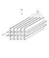
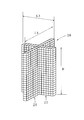
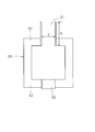
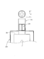
- FIG. 1 It is sectional drawing of the heating furnace which mounts an inorganic compounding molding. It is explanatory drawing which shows the mounting state of an inorganic compounding molding.
- a thermal efficiency improving device 10 for a heating device is a heating furnace 11 that is an example of a heating device.
- the heat-resistant inorganic material is disposed along the flow of the first example) so as not to block the flow of the exhaust gas (inserted directly into the exhaust gas passage 15 without using a support member) and heated by the exhaust gas.
- the composite molded product 16 is included. Thereby, the radiant heat radiated from the heated inorganic composite molded product 16 is returned to the heating chamber 12 through the exhaust gas passage 15 and the exhaust port 14, thereby reducing the heat flowing away from the heating chamber 12 to the outside. I am letting. Details will be described below.
- the inorganic composite molded product 16 is an assembled body (aggregate) formed by incorporating a plurality of plate-like materials 17 and 18 in a lattice shape in plan view. Body).
- the exhaust gas flows along the flat objects 17 and 18 and the side portions of the exhaust gas path 15. And when exhaust gas passes along the flat objects 17 and 18, heat exchange is performed between the flat objects 17 and 18, and the flat objects 17 and 18 (inorganic composite molding 16) are carried out. Heated.
- the inorganic composite molded product 16 may be fixed in the exhaust gas path 15 via a support member in addition to being directly installed in the exhaust gas path 15.
- the supporting member is manufactured using a heat-resistant iron-chromium wire and its wire mesh, a high heat-resistant oxide (for example, alumina), or a high heat-resistant non-oxide (for example, silicon carbide, silicon nitride, sialon). To do. As a result, deformation and breakage of the support member at a high temperature can be prevented, and the support member can be used stably over a long period of time.
- the structure having a blade-shaped member is, for example, an inorganic composite molded product that covers (heat shields) a fan blade installed in a passage through which heated gas passes or forms a blade itself, or a passage.
- the flat object 17 has a half of the length L1 of the flat object 17 along the longitudinal direction at a portion that divides the length W1 of the flat object 17 into six equal parts.
- a notch 19 (width T1 is 0.5 to 1 mm larger than the thickness of the flat plate 18) is formed, and the flat plate 18 has a width W2 of the flat plate 18 in the width direction.
- a cut 20 having a length half the length L2 of the flat plate 18 along the longitudinal direction (width T2 is 0.5 to 1 mm larger than the thickness of the flat plate 17) is formed in a portion equally divided into three. Is formed. Then, the notch 19 of the flat plate 17 and the notch 20 of the flat plate 18 are inserted and combined along the cuts 19 and 20, thereby forming the inorganic composite molded product 16 shown in FIG.
- the flat objects 17 and 18 include an inner layer and an outer layer made of an inorganic material coating that protects the inner layer from the heated gas.
- the inner layer is formed of a reinforcing material made of a cloth member formed of heat-resistant inorganic fibers and a ceramic matrix filled in the space of the reinforcing material.
- a fiber processed product using heat-resistant inorganic fibers for example, a one-way aligned laminate of long fibers made of heat-resistant inorganic fibers, It is possible to use a reinforcing material formed using a short-fiber 1-70 mm short fiber cross-complex or oriented body made of heat-resistant inorganic fibers).
- the cloth member is formed by cutting a cloth material formed from a woven fabric having a thickness of 0.2 to 10 mm and an opening ratio of 30% or less, or a nonwoven fabric having a thickness of 1 to 10 mm and a volume porosity of 50 to 97%.
- the woven fabric is any one of plain weave, satin weave, twill weave, three-dimensional weave, and multiaxial weave. Thereby, the optimal cloth member according to the objective can be obtained by selecting the kind of textiles.
- the cloth member is either one or both of a woven fabric having a thickness of 0.2 mm to 10 mm, an opening ratio of 30% or less, and a nonwoven fabric having a thickness of 1 mm to 10 mm and a volume porosity of 50% to 97%. It can also be formed from a laminated fabric laminate.
- the cloth member is manufactured by cutting a cloth material composed of composite inorganic fibers (an example of heat-resistant inorganic fibers) having a multilayer structure having an inner shell structure and an outer shell structure.
- the inner shell structure is (1) an inorganic substance containing Si, C, O, and Me, where Me is one metal component selected from Ti, Zr, and Al, and (2) Ti, Zr, One metal component selected from Al and Al is Me, one metal component selected from Ti and Zr is Ms, and its carbide is MsC.
- the outer shell structure is Al, Ti, Cr, Fe, Si, Co, Ni, Cu, Y, Zr, Nb, Tc, Ru, Rh, Pd, Ag, La, Ce, Pr, Nd, Pm, Sm. , Eu, Gd, Tb, Dy, Ho, Er, Tm, Yb, Lu, Hf, Ta, Re, and Os as the first group, (1) of one element selected from the first group Oxide, (2) a composite oxide composed of two or more elements selected from the first group, (3) a solid solution oxide of two or more elements selected from the first group, and (4) a composite oxidation with oxides (5) oxide and solid solution oxide, (6) composite oxide and solid solution oxide, and (7) oxide, composite oxide and solid solution oxide. .
- the value of the thermal expansion coefficient of the inorganic substance forming the outer shell structure is within ⁇ 10% of the value of the thermal expansion coefficient of the inorganic substance forming the inner shell structure, and the thickness of the outer shell structure is It is 0.2 ⁇ m or more and 10 ⁇ m or less. Thereby, even if temperature variation occurs in the composite inorganic fiber, it is possible to prevent the outer shell structure from being separated from the inner shell structure.
- each element of Y, Yb, Er, Ho, and Dy is a second group
- each element of Y, Yb, Er, Ho, Dy, Gd, Sm, Nd, and Lu is a third group.
- the general formulas Q 2 Si 2 O 7 , QSiO 5 , R 3 It consists of one or more of Al 5 O 12 and RAlO 3 .
- any one of C, BN, Si 3 N 4 , Si—N amorphous inorganic material, and Si—N—O amorphous inorganic material is provided between the inner shell structure and the outer shell structure.
- an intervening layer consisting of a combination of two or more and having a thickness of 0.1 to 3.0 ⁇ m is present. Thereby, the brittle fracture of the inner shell structure can be prevented.
- an internal layer is formed by forming a ceramic matrix with the following method, for example.
- the cloth member is immersed (impregnated) in a solution in which the organosilicon compound is dissolved at room temperature and then taken out from the solution.
- a non-oxidizing atmosphere for example, a nitrogen gas atmosphere
- a non-oxidizing atmosphere for example, a nitrogen gas atmosphere
- the ceramic matrix which consists of the mineralization product obtained from an organosilicon compound can be filled into the space
- the impregnation of the organosilicon compound and the heat treatment are further repeated, so that the filling rate of the ceramic matrix existing in the voids of the composite inorganic fibers is increased. Can be improved.
- the ceramic matrix is (1) inorganic containing Si, C, O, and Md, where Md is one metal component selected from Ti, Zr, and Al. (2) One metal component selected from Ti, Zr, and Al is Md, one metal component selected from Ti, Zr is Mp, and its carbide is MpC.
- ⁇ -SiC 1) Between crystalline ultrafine particles having a particle diameter of 700 nm or less containing MpC, 3) a solid solution of ⁇ -SiC and MpC and / or MpC 1-x (0 ⁇ x ⁇ 1), and crystalline ultrafine particles And any one of the aggregates with the amorphous inorganic substance containing Si, C, O, and Md.
- the ceramic matrix contains (3) Si, C, and O present between the crystalline ultrafine particles of ⁇ -SiC having a particle diameter of 700 nm or less and the crystalline fine particles And (4) an amorphous inorganic material composed of Si, C, and O, and (5) a crystalline inorganic material composed of ⁇ -SiC microcrystals.
- the ceramic matrix is composed of (6) a crystalline inorganic substance composed of ⁇ -SiC microcrystals.
- the ceramic matrix is made of (7) a crystalline inorganic substance composed of ⁇ -SiC microcrystals, which are carbonization reaction products, by injecting molten silicon after carbon is present in the voids of the composite inorganic fiber, (8) A crystalline inorganic substance composed of microcrystals of ⁇ -SiC, which is a carbonization reaction product, by injecting molten silicon and a carbon compound (for example, methane, ethane) into the voids of the composite inorganic fiber and reacting them.
- a carbon compound for example, methane, ethane
- the composite inorganic fiber with SiC fine powder containing a sintering aid and heating it, it is composed of any one of crystalline inorganic substances consisting of ⁇ -SiC microcrystals that are sintering reaction products You can also
- the organosilicon compound a silazane-based polymer containing Si and N can also be used.
- the ceramic matrix is composed of (10) Si—N amorphous inorganic material, (11) Si—N—O amorphous inorganic material, (12) Si 3 N 4 crystalline Fine particles, (13) Si—N amorphous inorganic substance and Si 3 N 4 crystalline ultrafine particles, (14) Si—N—O amorphous inorganic substance and Si 3 N 4 crystalline ultrafine particles 1 is composed.
- Si 3 N 4 fine powder containing a sintering aid is filled in the voids of the composite inorganic fiber and heated, and heated, and Si 3 N 4 crystalline ultrafine particles as a sintered reaction product are heated. Any one of the above can also be used.
- the inorganic material coating forming the outer layer is Al, Ti, Cr, Fe, Si, Co, Ni, Cu, Y, Zr, Nb, Tc, Ru, Rh, Pd, Ag, La, Ce, Pr, Nd. , Pm, Sm, Eu, Gd, Tb, Dy, Ho, Er, Tm, Yb, Lu, Hf, Ta, Re, and Os as the first group, (1) selected from the first group 1) an oxide of one element, (2) a composite oxide composed of two or more elements selected from the first group, (3) a solid solution oxide of two or more elements selected from the first group, (4) oxidation A material A composed of any one of (5) oxide and solid solution oxide, (6) complex oxide and solid solution oxide, and (7) oxide, complex oxide and solid solution oxide.
- the outer layer has a thickness of 0.2 ⁇ m or more and 10 ⁇ m or less. Thereby, the long-term durability under high temperature and severe conditions of the inorganic composite molded product can be improved.
- the solid solution oxide includes Y, Yb, Er, Ho, and Dy elements as the second group, and Y, Yb, Er, Ho, Dy, Gd, Sm, Nd, and Lu elements as the third group.
- the general formulas Q 2 Si 2 O 7 , QSiO 5 , R 3 Al It consists of any one or more of 5 O 12 and RAlO 3 .
- the outer layer made of the inorganic material coating that protects the inner layer from the heated gas is formed, for example, by the following method.
- the inner layer (a cloth member in which the ceramic matrix is filled in the voids) is immersed in a solution in which the material A is dispersed, and the powder of the material A is adhered to the surface of the inner layer by electrophoresis.
- the internal layer to which the powder of the material A is adhered is taken out from the solution, dried, and then heat-treated in a non-oxidizing atmosphere, whereby the powder of the material A is sintered and fixed to the internal layer.
- an inorganic material covering made of a sintered layer of the material A is formed as an outer layer outside the inner layer.
- the heat treatment conditions in the non-oxidizing atmosphere (for example, the type of the non-oxidizing atmosphere, the heat treatment temperature, the heat treatment time, the atmospheric pressure during the heat treatment, etc.) are determined based on the composition of the material A.
- one metal component selected from Ti, Zr and Al is defined as Me, and is composed of an inorganic substance containing Si, C, O, and Me.
- Made of heat-resistant inorganic fiber (2) heat-resistant inorganic fiber made of inorganic material containing Si, C, and O, or (3) made of crystalline inorganic material made of ⁇ -SiC microcrystals
- Fabric M formed using heat-resistant inorganic fibers in the case of woven fabric, the thickness is 0.2 to 10 mm and the opening ratio is 30% or less, and in the case of nonwoven fabric, the thickness is 1 to 10 mm and the volume porosity is
- the fabric member M can also be manufactured from the above.
- the particle size contains 1) ⁇ -SiC, 2) MpC, 3) a solid solution of ⁇ -SiC and MpC and / or MpC 1-x (0 ⁇ x ⁇ 1).
- An aggregate of crystalline ultrafine particles of 700 nm or less and an amorphous inorganic material containing Si, C, O, and Md existing between the crystalline ultrafine particles is included.
- the inorganic substance containing Si, C, and O includes an amorphous material containing Si, C, and O present between the crystalline ultrafine particles of ⁇ -SiC having a particle diameter of 700 nm or less and the crystalline fine particles. Aggregates with fine inorganic substances are included.
- the method of filling the voids of the fabric member M with the ceramic matrix can be performed in the same manner as in the case of using a fabric member composed of composite inorganic fibers.
- the fabric material M used to fabricate the fabric member M contains chemical fibers (for example, rayon fibers), or when a sizing agent is applied to the fabric material.
- the fabric member M produced by cutting M is heat-treated in an inert gas atmosphere (nitrogen gas atmosphere, preferably argon gas atmosphere) at a temperature of 800 to 1200 ° C. for 0.5 to 5 hours to be completely inorganic. (Chemical fiber is completely decomposed and removed, or part is decomposed and removed, and the remainder is carbonized, and the sizing agent is completely removed).
- an inert gas atmosphere nitrogen gas atmosphere, preferably argon gas atmosphere
- C, BN, Si 3 N 4 , Si—N-based amorphous inorganic material, and Si—N—O-based non-coated material are formed on the surface of the heat-resistant inorganic fiber constituting the fabric member M that has been completely inorganicized.
- a coating layer made of any one or a combination of two or more crystalline inorganic substances and having a thickness of 0.1 to 3.0 ⁇ m is provided.
- the fabric member M was produced from the fabric material M formed using heat-resistant inorganic fibers having no inner shell structure and outer shell structure, and the gap of the fabric member M was filled with the ceramic matrix.
- the surface of the heat-resistant inorganic fiber is formed by, for example, attaching the powder of the material A by electrophoresis on the outside of the heat-resistant inorganic fiber forming the cloth member M and performing heat treatment.
- a sintered layer made of the material A may be fixed to.
- the heat resistant inorganic fiber which forms the cloth member M can be changed into the state of a composite inorganic fiber, and the corrosion resistance of the heat resistant inorganic fiber can be improved.
- C, BN, Si 3 N 4 , Si—N amorphous inorganic substance, and Si—N—O amorphous inorganic substance are formed on the surface of the heat resistant inorganic fiber forming the cloth member M. It is preferable that an intervening layer comprising any one or a combination of two or more and having a thickness of 0.1 to 3.0 ⁇ m is present. Thereby, the brittle fracture
- the thermal efficiency improvement method of the heating apparatus using the thermal efficiency improvement apparatus 10 of the heating furnace which concerns on one Example of this invention is demonstrated.
- the exhaust gas is a flat plate 17 constituting the inorganic composite molded product 16
- the gaps between the plates 18 and the flat objects 17 and 18 and the side portions of the exhaust gas passage 15 flow along the exhaust gas passage 15 and are discharged to the outside.
- the inorganic composite molded product 16 flat plates 17 and 18
- the inorganic composite in the exhaust gas path 15 is radiated by the radiant heat radiated from the heated inorganic composite molded product 16.
- the region upstream of the position where the molded product 16 is installed is heated and the temperature rises.
- the radiant heat radiated from the upstream region of the exhaust gas passage 15 increases, and a part of the heat enters the heating chamber 11 to reduce the heat flowing out of the heating furnace 11 to the outside. it can.
- the exhaust gas flows along the exhaust gas path 15 through the gap between the flat objects 17 and 18 and the gap between the flat objects 17 and 18 and the side of the exhaust gas path 15. Since the passage of the exhaust gas is not hindered even if the composite molded product 16 is installed, the flow of the gas in the furnace in the heating chamber 12 is the same as the case where the inorganic composite molded product 16 is not installed in the exhaust gas path 15.
- the thermal efficiency improving apparatus 10 can be easily applied to the existing heating furnace 11 without fear of an increase in furnace pressure. Furthermore, since the inorganic composite molded product 16 can be easily attached to and removed from the exhaust gas passage 15, maintenance management of the thermal efficiency improvement device 10 is facilitated.
- the inorganic composite molded product 16 includes an inner layer and an outer layer made of an inorganic material covering for protecting the inner layer, and the inorganic material covering forming the outer layer is made of Al, Ti, Cr, Fe. Si, Co, Ni, Cu, Y, Zr, Nb, Tc, Ru, Rh, Pd, Ag, La, Ce, Pr, Nd, Pm, Sm, Eu, Gd, Tb, Dy, Ho, Er, Tm , Yb, Lu, Hf, Ta, Re, and Os as a first group, (1) an oxide of one element selected from the first group, (2) 2 selected from the first group (3) a solid solution oxide of two or more elements selected from the first group, (4) an oxide and a complex oxide, (5) an oxide and a solid solution oxide, (6) 1) any of complex oxide and solid solution oxide, and (7) oxide, complex oxide and solid solution oxide.
- the thickness of the outer layer since a 0.2 ⁇ m or 10 ⁇ m or less, even if the temperature variation occurs in the outer layer, it is possible to prevent the outer layer is peeled off from the inner layer.
- the exhaust gas contains a component that degrades the inner layer, the deterioration of the characteristics (for example, the decrease in strength, the decrease in thermal emissivity, etc.) due to the material change of the inner layer is suppressed.
- the solid solution oxide includes Y, Yb, Er, Ho, and Dy elements as the second group, and Y, Yb, Er, Ho, Dy, Gd, Sm, Nd, and Lu elements as the second group.
- the third group when at least one element selected from the second group is Q and at least one element selected from the third group is R, the general formulas Q 2 Si 2 O 7 , QSiO 5 , R 3 When composed of one or more of Al 5 O 12 and RAlO 3 , the heat resistance and corrosion resistance of the solid solution oxide (that is, the outer layer) can be improved, so that the material change of the inner layer is surely prevented. And the stability of the inner layer can be further enhanced.
- the inorganic composite molded product can easily follow the temperature fluctuation of the heating gas regardless of the material of the outer layer and becomes high temperature. In particular, the radiation efficiency of radiant heat can be increased.
- the inner shell structure and outer shell structure of the composite inorganic fiber forming the reinforcing material of the inner layer are each formed of the inorganic material having the composition shown above, even if temperature fluctuation occurs in the outer shell structure The outer shell structure can be prevented from peeling from the inner shell structure, the inner shell structure can be protected from the heated gas, and the stability of the inner shell structure can be enhanced.
- reference numeral 23 denotes a manual damper
- 24 denotes an opening that is normally closed with a refractory brick.
- the dimensions a, b, and c of the heating chamber 12 are, for example, 700 mm, 400 mm, and 455 mm, but the present invention is not limited to this dimension.
- the opening 24 acts as a cold air vent when the refractory brick is removed.
- Non-woven fabric produced using heat-resistant inorganic fibers formed of an inorganic substance containing Si, C, O, and Zr fiber diameter is 11 ⁇ m, fiber basis weight is 240 g / m 2 , volume porosity is 95%, chemical fiber 2) containing 20% by mass of rayon fiber, which is an example of a roll having a width of 500 mm, a thickness of 5 mm, and a length of 10 m, and cutting two substrates having a length L1 of 320 mm and a width W1 of 200 mm
- Five substrates having a length L2 of 320 mm and a width W2 of 110 mm were produced.
- the base material is set in a heat treatment furnace, and heat-treated at 800 ° C. for 1 hour in an argon gas atmosphere to decompose and remove part of the rayon fibers contained in the base material (nonwoven fabric) to carbonize the remainder.
- the sizing agent (organic matter) applied to the substrate was removed (first step).
- the heat-treated substrate is bonded by two stainless steel meshes serving as anode electrodes, and yttrium monosilicate (Y 2 SiO 5 ), which is a solid solution oxide composed of Si and Y elements selected from the first group.
- Y 2 SiO 5 yttrium monosilicate
- Dispersion (with a particle diameter of 1 ⁇ m or less) uniformly dispersed in an ethanol solvent (100 parts of ethanol, 2.5 parts of Y 2 SiO 5 fine powder, 0.02 part of cyclohexanol-based dispersant, 0 polyvinyl butyral as a binder) 0.02 parts added and ultrasonically dispersed and adjusted) and placed between two cathode electrodes made of C / C composite that face each other at a distance.
- ethanol solvent 100 parts of ethanol, 2.5 parts of Y 2 SiO 5 fine powder, 0.02 part of cyclohexanol-based dispersant, 0 polyvinyl butyral as a binder
- the substrate was taken out from the dispersion solution, drained, air-dried for 2 hours, and hot-air dried for 6 hours at 40 ° C. in the air atmosphere (third step), and then under a slight pressure of 0.5 MPa in an argon gas atmosphere
- the refractory inorganic fiber is made to have an inner shell structure by sintering at 1400 ° C. for 3 hours to sinter the yttrium monosilicate powder adhered to the outside of the refractory inorganic fiber and fix it to the refractory inorganic fiber.
- the cloth member After immersing the cloth member in a solution of 30% by weight of polyzirconocarbosilane uniformly dissolved in a xylene solvent at room temperature, the cloth member is taken out from the solution and dried in a nitrogen gas atmosphere at 150 ° C. for 2 hours to be included in the cloth member.
- the xylene solvent was removed to prepare 7 fabric members (contained in the voids of the fabric member) containing polyzirconocarbosilane (fifth step).
- Si, C, O which are mineralized products obtained by baking a cloth member containing polyzirconocarbosilane for 1 hour at 1200 ° C.
- the fifth step and the sixth step are further repeated three times to obtain a fabric member ( A non-woven fabric composed of composite inorganic fibers) and a ceramic matrix comprising an inorganic substance containing Si, C, O and Zr, which are mineralized products obtained by thermal decomposition of polyzirconocarbosilane
- a fabric member A non-woven fabric composed of composite inorganic fibers
- a ceramic matrix comprising an inorganic substance containing Si, C, O and Zr, which are mineralized products obtained by thermal decomposition of polyzirconocarbosilane
- the molded body obtained in the eighth step is bonded with two stainless steel metal meshes serving as anode electrodes, and a solid solution oxide yttrium monosilicate (Y 2 SiO 5 ) powder (particle size of 1 ⁇ m or less) is placed in an ethanol solvent.
- Uniformly dispersed solution 100 parts of ethanol, 2.5 parts of Y 2 SiO 5 fine powder, 0.02 part of cyclohexanol dispersant, 0.02 part of polyvinyl butyral as a binder is added, and ultrasonically dispersed to adjust
- a DC voltage of 100 V was applied for 30 minutes from a DC stabilized power source at 25 ° C., and yttrium monosilicate powder was adhered to the surface of the molded body by electrophoresis (9th step).
- the molded product was taken out from the dispersion, drained, air-dried for 2 hours, and hot-air dried at 40 ° C. for 6 hours in the air atmosphere (10th step), and then subjected to a slight pressure of 0.5 MPa in an argon gas atmosphere. Then, heat treatment is performed at 1400 ° C. for 3 hours to sinter the yttrium monosilicate powder adhering to the surface of the molded body and fix it to the molded body, so that the inner layer portion is a cloth member (composite inorganic fiber).
- the outer layer portion is formed of a reinforcing material of a configured non-woven fabric) and a ceramic matrix made of an inorganic substance containing Si, C, O, and Zr, which are mineralized products obtained by thermal decomposition of polyzirconocarbosilane.
- inorganic composite moldings that are inorganic material coatings made of yttrium monosilicate for further improving the durability (length L1 is 320 mm, width W1 is 200 mm, thickness 3) m is two, vertical L2 is 320 mm, the lateral W2 is 110 mm, a thickness of 3mm is 5 sheets) were prepared (eleventh step).
- the seven inorganic composite molded products obtained in the eleventh step are assembled in a lattice shape as shown in FIG. 2 using the provided incisions, and the installation location is fixed with an alumina-based heat-resistant adhesive.
- An apparatus for improving the thermal efficiency of a heating device made of an inorganic composite molded product incorporated in a lattice shape was produced.
- the inorganic composite molded product 16 that is the thermal efficiency improving device 10 of the heating device was inserted along the flow of the heated gas into the exhaust gas passage 15 that is the passage of the heated gas.
- the high-temperature gas kiln is a ceiling arch type gas kiln equipped with six to three pairs of LPG venturi burners.
- the hearth 13 has a width of 19 to 29 mm and a length of, for example, 200 mm to 450 mm. Are arranged side by side, and the heated gas in the furnace flows into the exhaust gas path 15 through the exhaust port 14, passes through the inorganic composite molded product 16, and then has a manual damper 23 provided on the downstream side of the exhaust gas path 15. After that, it is released to the outside.
- the furnace pressure is finely adjusted by the manual damper 23.
- the temperature was raised from room temperature in 7.2 hours until the furnace temperature showed 1200 ° C., and the furnace temperature was kept constant at 1200 ° C.
- Time operation was performed, and the amount of LPG consumed was compared and compared with the case where the inorganic composite molded product was not attached.
- the total consumption of the fuel LPG when the inorganic composite molded product is mounted is 10080 liters (the LPG gas instantaneous average flow rate is 15 liters / minute), and the total consumption when the inorganic composite molded product is not mounted is 11424 liters.
- the LPG gas instantaneous average flow rate is 17 liters / minute. From this result, it is possible to reduce the LPG consumption rate by about 11.8% by mounting the inorganic composite molded product. It was found that the heating device showed excellent thermal efficiency improvement effect. In addition, almost the same result was obtained in the confirmation test of the same operation for 10 times thereafter, and no deterioration was found in the inorganic composite molded product recovered after the 10 confirmation tests. However, even at a high temperature of 1200 ° C., it was confirmed that stable performance could be maintained over a long period of time.
- Example 2 A plain fabric composed of heat-resistant inorganic fibers formed of an inorganic substance containing Si, C, and O (fiber basis weight is 289 g / m 2 , width is 500 mm, thickness is 0.33 mm, and length is 5 m. From a roll), one cloth member having a length of 200 mm, a width of 60 mm, and a thickness of 0.33 mm and two cloth members having a length of 200 mm, a width of 30 mm, and a thickness of 0.33 mm were cut out (first step).
- the fabric member is immersed at room temperature in a solution in which perhydropolysilazane, —Si (H 2 ) —NH—n, is uniformly dissolved in a xylene solvent at 20 wt%, and then taken out from the solution.
- the xylene solvent contained in the cloth member was removed by drying at 0 ° C. for 2 hours.
- the cloth member from which the xylene solvent has been removed is baked at 1200 ° C. for 1 hour in a nitrogen gas atmosphere, and the surface of the heat-resistant inorganic fiber constituting the plain fabric as the cloth member is Si—N-based (containing a trace amount of O).
- An inorganic substance amorphous inorganic substance composed of Si, N and / or Si 3 N 4 microcrystalline substance was coated (second step).
- the cloth member obtained in the second step (a plain woven fabric composed of heat-resistant inorganic fibers coated with Si-N inorganic material) was dissolved in a solution of 30% by weight of polycarbosilane uniformly dissolved in a xylene solvent at room temperature. After being soaked under the cloth, it is taken out from the solution and dried in a nitrogen gas atmosphere at 150 ° C. for 2 hours to remove the xylene solvent contained in the cloth member to contain the polycarbosilane (contained in the gap of the cloth member) 3 A sheet was produced (third step). Next, the cloth member containing polycarbosilane is fired at 1300 ° C.
- the third step and the fourth step were repeated twice more to obtain a cloth member (Si—N
- a molded body (finished body) formed in (5) was produced.
- using the molded body obtained in the fifth step instead of the solid solution oxide yttrium monosilicate (Y 2 SiO 4 ) powder used in Experimental Example 1, zircon (zirconium monosilicate), which is a solid solution oxide, is used.
- the treatment was performed in the same manner as the ninth step and the tenth step in Experimental Example 1 (the sixth step and the seventh step). Further, in the eleventh step of Experimental Example 1, 1400 ° C.
- the inner layer of the cloth member (inorganic coated with Si—N inorganic material) was treated in exactly the same way as the eleventh step of Experimental Example 1 except that the heat treatment was performed at 1500 ° C. for 0.5 hour instead of the heat treatment for 3 hours.
- the outer layer is a flat plate of a multilayer structure, which is an inorganic material coating made of zircon to further improve the durability (length 200 mm, width 60 mm, thickness 0.2 mm one, length 200 mm , Width 30 mm, thickness 0.2 mm 2 sheets) (8th step).
- the three flat plates obtained in the eighth step are cruciform lattices with wire meshes 26 and 27 of heat-resistant iron-chromium wires (wire diameter: 1 mm, 15 mesh).
- An inorganic composite molded product incorporated in a shape was formed to produce a thermal efficiency improving device 28 of a heating device (9th step).
- L3 and L4 are, for example, 60 mm
- H is, for example, 200 mm.
- the thermal efficiency improving device 28 for a heating device made of the obtained inorganic composite molded product has an inner diameter d of 60 mm and a height h formed at the center of the ceiling portion 30 of the electric furnace 29. Is inserted from the inlet side (furnace inside) of the 450 mm exhaust port 31, and the state of the iron-chromium wire meshes 26 and 27 sandwiching the inorganic composite molded product is prevented so that the inorganic composite molded product does not fall off. It was mounted while adjusting (mounted so that one end of the inorganic composite molded product coincided with the inlet position of the exhaust port 31).
- the electric furnace 29 is always kept at 800 ° C. (controlled by the temperature at the center of the electric furnace) Then, air is circulated in the electric furnace 29 at a flow rate of 1 liter / min from the air inlet 33 formed in the center portion of the hearth 32 of the electric furnace 29, and the power consumption W1 of the electric furnace 29 at that time is reduced. The rate was examined.
- the reduction rate of the power consumption P1 is such that air is discharged from the air inlet 33 in the center of the hearth at a flow rate of 1 liter / min without installing a thermal efficiency improvement device in the exhaust port 31 of the electric furnace 29.
- the electric power is calculated by 100 ⁇ (P0 ⁇ P1) / P0.
- the thermal efficiency improvement device 28 was installed, the power consumption reduction rate showed a value of 12% compared to the case where it was not installed, and this reduction rate was constant without changing over 10 hours.
- the inorganic composite molded product has an excellent radiant heat radiation action, which greatly contributes to energy saving in the operation of the electric furnace 29, and as a result, it is suggested that it greatly contributes to reduction of CO 2 generation. It was.
- Nonwoven fabric composed of heat-resistant inorganic fibers formed of an inorganic substance containing Si, C, O and Ti (fiber diameter is 11 ⁇ m, fiber basis weight is 240 g / m 2 , volume porosity is 95%, an example of chemical fiber 20% by weight of rayon fiber, and rolled into a roll having a width of 500 mm, a thickness of 5 mm, and a length of 10 m), and a single substrate having a length of 200 mm, a width of 60 mm, and a thickness of 5 mm, Two substrates having a thickness of 200 mm, a width of 30 mm, and a thickness of 5 mm were produced.
- the base material is set in a heat treatment furnace, and heat-treated at 800 ° C. for 1 hour in an argon gas atmosphere to decompose and remove part of the rayon fibers contained in the base material (nonwoven fabric) to carbonize the remainder.
- the sizing agent (organic matter) applied to the substrate was removed (first step).
- the heat-treated base material is bonded with two stainless steel meshes serving as anode electrodes, and zircon (also called zirconium monosilicate, ZrSO 4 ), which is a solid solution oxide composed of elements of Si and Zr selected from the first group.
- zircon also called zirconium monosilicate, ZrSO 4
- Dispersion solution 100 parts ethanol, 2.5 parts zircon powder, 0.02 parts cyclohexanol dispersant, 0.02 part polyvinyl butyral as a binder
- a powder particle size of 1 ⁇ m or less
- the distance between the two cathode electrodes made of C / C composite disposed opposite to each other is provided.
- the substrate was taken out of the dispersion solution, drained, air-dried for 2 hours, and hot-air dried for 6 hours at 40 ° C. in the air atmosphere (third step), and then under a slight pressure of 0.5 MPa in an argon gas atmosphere, Heat treatment is performed at 1500 ° C. for 0.5 hours to sinter the zircon powder adhered to the outside of the heat-resistant inorganic fiber and fix it to the heat-resistant inorganic fiber.
- a cloth member made of a nonwoven fabric composed of composite inorganic fibers having a thickness of 1 mm, a length of 200 mm, a width of 30 mm, and a thickness of 2 mm was prepared (fourth step).
- the cloth member is immersed in a solution in which 30% by weight of polytitanocarbosilane is uniformly dissolved in a xylene solvent at room temperature, then taken out from the solution and dried in a nitrogen gas atmosphere at 150 ° C. for 2 hours to be contained in the cloth member.
- the xylene solvent was removed, and three cloth members (contained in the voids of the cloth member) containing polytitanocarbosilane were produced (fifth step).
- the cloth member containing polytitanocarbosilane is heat treated at 1300 ° C.
- Si, C, O which are mineralized products obtained by thermal decomposition of polytitanocarbosilane.
- an inorganic substance containing Ti and producing a primary body of a molded body formed of a reinforcing material for a cloth member and a ceramic matrix made of an inorganic substance containing Si, C, O and Ti. (6th process).
- the fifth step and the sixth step are repeated four more times to form a cloth member (composed of composite inorganic fibers).
- a non-woven fabric reinforcement and a molded body made of a ceramic matrix made of an inorganic substance containing Si, C, O, and Ti, which are mineralized products obtained by thermal decomposition of polytitanocarbosilane Body) (seventh step).
- the molded body obtained in the seventh step was used in exactly the same manner as in the ninth to eleventh steps of Experimental Example 1, and the inner layer was made of a cloth member (composed of composite inorganic fibers).
- Non-woven fabric and a ceramic matrix composed of an inorganic substance containing Si, C, O and Ti, which are mineralized products obtained by thermal decomposition of polytitanocarbosilane, and the outer layer is
- Three inorganic composite moldings with a multilayer structure which is an inorganic material coating made of yttrium monosilicate for further improving durability (200 mm in length, 60 mm in width, 1 in 3 mm in thickness, 200 mm in length, 30 mm in width) , 2 mm in thickness 3 mm) were produced (eighth step).
- the thermal efficiency improvement device When the thermal efficiency improvement device was installed in this test, the power consumption reduction rate showed a high value of 20% compared to the case where it was not installed, and this reduction rate remained constant for 300 hours and was incorporated into a cross shape. It was confirmed that the inorganic composite molded product has an excellent radiant heat radiation effect, and it was suggested that it greatly contributes to energy saving in the operation of the electric furnace and consequently contributes greatly to reduction of CO 2 generation. In addition, when the inorganic composite molded product recovered after the test was observed, no change such as deterioration was observed, and it was confirmed that it could maintain a constant performance at a high temperature of 1200 ° C. for a long period of time. .
- the present invention has been described above with reference to the embodiments. However, the present invention is not limited to the configurations described in the above-described embodiments, and is within the scope of the matters described in the claims. Other possible embodiments and modifications are also included. Further, the present invention includes a combination of components included in the present embodiment and other embodiments and modifications. For example, in this embodiment, non-oxide heat-resistant inorganic fibers are used, but heat-resistant inorganic fibers made of an inorganic material containing Al, Si, and O can also be used.
- Heating the inorganic composite molded product with heated gas and returning the radiant heat from the heated inorganic composite molded product into the heating device reduces the heat that flows out of the heating device, increasing the efficiency of the heating device. Energy loss can be reduced.
Landscapes
- Engineering & Computer Science (AREA)
- Chemical & Material Sciences (AREA)
- Ceramic Engineering (AREA)
- Manufacturing & Machinery (AREA)
- Materials Engineering (AREA)
- Structural Engineering (AREA)
- Organic Chemistry (AREA)
- Inorganic Chemistry (AREA)
- General Engineering & Computer Science (AREA)
- Mechanical Engineering (AREA)
- Chemical Kinetics & Catalysis (AREA)
- Environmental & Geological Engineering (AREA)
- Physics & Mathematics (AREA)
- Thermal Sciences (AREA)
- Waste-Gas Treatment And Other Accessory Devices For Furnaces (AREA)
- Resistance Heating (AREA)
- Ceramic Products (AREA)
Abstract
耐熱性の無機複合化成形物16を、加熱機器11から発生する加熱ガスの通路15に、通路15に沿って、かつ通路15を通過する加熱ガスの流れを遮断することなく設置し、加熱ガスで無機複合化成形物16を加熱し、加熱された無機複合化成形物16からの輻射熱を加熱機器11内に戻し入れて、加熱機器11から外部に流出する熱を減少させる加熱機器の熱効率改善方法であって、無機複合化成形物16は、内部層と内部層を加熱ガスから保護する無機材料被覆物からなる外部層とを備える。
Description
本発明は、加熱機器の加熱ガスの通路、例えば、加熱炉の排気口内又は排気口に連通する排気ガス経路内に設置して、通過する加熱ガス(排気ガス)で加熱されて加熱炉内からの輻射熱を加熱炉内に放射することにより、加熱炉内から外部に流出する熱を減少させる加熱機器の熱効率改善方法及び加熱機器の熱効率改善装置に関する。
ガス燃焼式あるいは雰囲気制御用の加熱炉における熱損失として最も顕著なものは、加熱炉の加熱室に設けた排気口を通過して加熱炉の外部に放出される高温の排気ガスが持ち出す熱である。そこで、耐熱性の布部材を加熱炉の排気口内に、通過する排気ガスの流れに沿って設置して布部材を加熱し、加熱された布部材により輻射熱を加熱炉内に放射することにより、排気口から外部に流出する熱を減少させる加熱炉の熱効率改善方法及び熱効率改善装置が提案されている(例えば、特許文献1参照)。
しかしながら、布部材を排気口内に安定して配置するには支持部材を使用する必要があり、排気口内への布部材の設置が煩雑になるという問題がある。また、支持部材を用いることから、布部材の設置場所に制約が生じるという問題がある。更に、通過する排気ガスにより布部材に振動が発生すると、布部材が早期に破損するという問題が生じるため、長期間に亘って布部材を安定して設置することが困難となる。
本発明はかかる事情に鑑みてなされたもので、加熱機器の加熱ガスの通路の任意の場所に、容易に、しかも長期間に亘って安定して設置することができ、通過する加熱ガスで加熱されて加熱機器内からの輻射熱を加熱機器内に放射する(戻す)ことにより、加熱機器内から外部に流出する熱を減少させる加熱機器の熱効率改善方法及び加熱機器の熱効率改善装置を提供することを目的とする。
前記目的に沿う第1の発明に係る加熱機器の熱効率改善方法は、耐熱性の無機複合化成形物を、加熱機器から発生する加熱ガスの通路に、該通路に沿って、かつ該通路を通過する加熱ガスの流れを遮断することなく設置し、加熱ガスで前記無機複合化成形物を加熱し、加熱された前記無機複合化成形物からの輻射熱を前記加熱機器内に戻し入れて、前記加熱機器から外部に流出する熱を減少させる加熱機器の熱効率改善方法であって、前記無機複合化成形物は、内部層と該内部層を前記加熱ガスから保護する無機材料被覆物からなる外部層とを備える。
ここで、前記内部層を、耐熱性無機繊維で形成された強化材と、該強化材の空隙に充填されたセラミックマトリックスで形成し、更に、前記強化材は布部材又は繊維加工品を有して形成することができる。
第1の発明に係る加熱機器の熱効率改善方法において、前記無機複合化成形物は、1)平板体、2)円板体、3)複数の平板状物を、平面視して格子状に組み込んで形成した組み込み体、4)円筒体、5)中空円錐台体、6)中空の多角柱体、又は7)羽根型部材を有する構造体とすることができる。
ここで、羽根型部材を有する構造体とは、例えば、送風機の羽根車(風車)、軸流送風機あるいは軸流圧縮機に用いる回転羽根(回転羽根車)又は固定羽根(固定羽根を取り付けるケーシングを含む)をさす。
ここで、羽根型部材を有する構造体とは、例えば、送風機の羽根車(風車)、軸流送風機あるいは軸流圧縮機に用いる回転羽根(回転羽根車)又は固定羽根(固定羽根を取り付けるケーシングを含む)をさす。
第1の発明に係る加熱機器の熱効率改善方法において、前記無機複合化成形物を、支持部材を介して前記通路に設置することもできる。
第1の発明に係る加熱機器の熱効率改善方法において、前記布部材は、厚みが0.2mm以上10mm以下、開口率が30%以下の織物から作製され、該織物は、平織、繻子織、綾織、三次元織、及び多軸織のいずれか1とすることができる。
第1の発明に係る加熱機器の熱効率改善方法において、前記布部材は、厚みが1mm以上10mm以下、体積空隙率が50%以上97%以下の不織布から作製することもできる。
第1の発明に係る加熱機器の熱効率改善方法において、前記布部材は、厚みが0.2mm以上10mm以下、開口率が30%以下の織物及び厚みが1mm以上10mm以下、体積空隙率が50%以上97%以下の不織布のいずれか一方又は双方を重ね合わせて作製された布材積層物から形成してもよい。
第1の発明に係る加熱機器の熱効率改善方法において、前記繊維加工品は、前記耐熱繊維からなる長繊維の一方向引き揃え積層物又は該耐熱繊維からなる長さ1~70mmの裁断繊維(短繊維)とすることができる。
第1の発明に係る加熱機器の熱効率改善方法において、前記耐熱性無機繊維は、内殻構造と外殻構造を有する多層構造を備えた複合化無機繊維であって、前記外殻構造は、Al、Ti、Cr、Fe、Si、Co、Ni、Cu、Y、Zr、Nb、Tc、Ru、Rh、Pd、Ag、La、Ce、Pr、Nd、Pm、Sm、Eu、Gd、Tb、Dy、Ho、Er、Tm、Yb、Lu、Hf、Ta、Re、及びOsの各元素を第1群として、(1)前記第1群から選択された1の元素の酸化物、(2)前記第1群から選択された2以上の元素からなる複合酸化物、(3)前記第1群から選択された2以上の元素の固溶体酸化物、(4)前記酸化物と前記複合酸化物、(5)前記酸化物と前記固溶体酸化物、(6)前記複合酸化物と前記固溶体酸化物、及び(7)前記酸化物と前記複合酸化物と前記固溶体酸化物のいずれか1からなる材料Aで構成され、前記外殻構造を形成する無機物質の熱膨張係数の値は、前記内殻構造を形成する無機物質の熱膨張係数の値の±10%の範囲内にあり、前記外殻構造の厚さは0.2μm以上10μm以下であることが好ましい。
第1の発明に係る加熱機器の熱効率改善方法において、前記外殻構造を構成する前記固溶体酸化物は、Y、Yb、Er、Ho、及びDyの各元素を第2群とし、Y、Yb、Er、Ho、Dy、Gd、Sm、Nd、及びLuの各元素を第3群として、前記第2群から選択された少なくとも1の元素をQとし、前記第3群から選択された少なくとも1の元素をRとしたとき、一般式Q2Si2O7、QSiO5、R3Al5O12、及びRAlO3のいずれか1又は2以上からなることが好ましい。
第1の発明に係る加熱機器の熱効率改善方法において、前記内殻構造は、Ti、Zr、及びAlから選択される1の金属成分をMeとして、Si、C、O、及びMeを含有する無機物質で構成されていることが好ましい。
第1の発明に係る加熱機器の熱効率改善方法において、前記内殻構造は、Ti、Zr、及びAlから選択される1の金属成分をMeとし、Ti及びZrから選択される1の金属成分をMs、その炭化物をMsCとして、1)β-SiCと、2)MsCと、3)β-SiCとMsCとの固溶体及び/又はMsC1-x(0<x<1)とを含有する粒子径が700nm以下の結晶質超微粒子と、該結晶質超微粒子間に存在するSi、C、O、及びMeを含有する非晶質無機物質との集合物で構成することができる。
第1の発明に係る加熱機器の熱効率改善方法において、前記内殻構造は、Si、C、及びOを含有する非晶質無機物質で構成することもできる。
第1の発明に係る加熱機器の熱効率改善方法において、前記内殻構造は、粒子径が700nm以下であるβ-SiCの結晶質量微粒子と、該結晶質超微粒子間に存在するSi、C、及びOを含有する非晶質無機物質との集合物で構成してもよい。
第1の発明に係る加熱機器の熱効率改善方法において、前記内殻構造は、β-SiCの微結晶からなる結晶質無機物質で構成することもできる。
第1の発明に係る加熱機器の熱効率改善方法において、前記複合化無機繊維の前記内殻構造と前記外殻構造との間に、C、BN、Si3N4、Si-N系非晶質無機物質、及びSi-N-O系非晶質無機物質のいずれか1又は2以上の組み合わせからなり、厚さが0.1~3.0μmの介在層が存在することが好ましい。
第1の発明に係る加熱機器の熱効率改善方法において、前記耐熱性無機繊維は、Ti、Zr及びAlから選択される1の金属成分をMeとして、Si、C、O、及びMeを含有する無機物質で構成されていることが好ましい。
第1の発明に係る加熱機器の熱効率改善方法において、前記耐熱性無機繊維は、Si、C、及びOを含有する無機物質で構成することもできる。
第1の発明に係る加熱機器の熱効率改善方法において、前記耐熱性無機繊維は、β-SiCの微結晶からなる結晶質無機物質で構成してもよい。
第1の発明に係る加熱機器の熱効率改善方法において、前記耐熱性無機繊維は、Al、Si、及びOを含有する無機物質で構成することもできる。
第1の発明に係る加熱機器の熱効率改善方法において、前記耐熱性無機繊維は、C、BN、Si3N4、Si-N系非晶質無機物質、及びSi-N-O系非晶質無機物質のいずれか1又は2以上の組み合わせからなり、厚さが0.1~3.0μmの被覆層を有することが好ましい。
第1の発明に係る加熱機器の熱効率改善方法において、前記セラミックマトリックスは、ポリメタロカルボシランを熱分解して得られる無機化生成物であって、Ti、Zr、及びAlから選択される1の金属成分をMdとして、Si、C、O、及びMdを含有する無機物質で構成されていることが好ましい。
第1の発明に係る加熱機器の熱効率改善方法において、前記セラミックマトリックスは、ポリメタロカルボシランを熱分解して得られる無機化生成物であって、Ti、Zr、及びAlから選択される1の金属成分をMdとし、Ti、Zrから選択される1の金属成分をMp、その炭化物をMpCとして、1)β-SiCと、2)MpCと、3)β-SiCとMpCとの固溶体及び/又はMpC1-x(0<x<1)とを含有する粒子径が700nm以下の結晶質超微粒子と、該結晶質超微粒子間に存在するSi、C、O、及びMdを含有する非晶質無機物質との集合物で構成することができる。
第1の発明に係る加熱機器の熱効率改善方法において、前記セラミックマトリックスは、ポリカルボシランを熱分解して得られる無機化生成物であって、粒子径が700nm以下であるβ-SiCの結晶質超微粒子と該結晶質微粒子間に存在するSi、C、及びOを含有する非晶質無機物質との集合物、又は、Si、C、及びOからなる非晶質無機物質で構成してもよい。
第1の発明に係る加熱機器の熱効率改善方法において、前記セラミックマトリックスは、ポリアルミノカルボシランの熱分解生成物、ポリカルボシランの熱分解生成物、溶融シリコンと炭素との炭化反応生成物、溶融シリコンと炭素化合物との炭化反応生成物、及び焼結助剤を含むSiC微粉末の焼結反応生成物のいずれか1であって、β-SiCの微結晶からなる結晶質無機物質で構成することもできる。
第1の発明に係る加熱機器の熱効率改善方法において、前記セラミックマトリックスは、1)Si及びNを含有するシラザン系ポリマーを熱分解して得られる無機化生成物であって、Si-N系非晶質無機物質、Si-N-O系非晶質無機物質、Si3N4結晶質超微粒子、Si-N系非晶質無機物質とSi3N4結晶質超微粒子、及びSi-N-O系非晶質無機物質とSi3N4結晶質超微粒子のいずれか1で構成されている、又は2)焼結助剤を含むSi3N4微粉末の焼結反応生成物であるSi3N4結晶質超微粒子で構成されていてもよい。
第1の発明に係る加熱機器の熱効率改善方法において、前記外部層を形成する前記無機材料被覆物は、Al、Ti、Cr、Fe、Si、Co、Ni、Cu、Y、Zr、Nb、Tc、Ru、Rh、Pd、Ag、La、Ce、Pr、Nd、Pm、Sm、Eu、Gd、Tb、Dy、Ho、Er、Tm、Yb、Lu、Hf、Ta、Re、及びOsの各元素を第1群として、(1)前記第1群から選択された1の元素の酸化物、(2)前記第1群から選択された2以上の元素からなる複合酸化物、(3)前記第1群から選択された2以上の元素の固溶体酸化物、(4)前記酸化物と前記複合酸化物、(5)前記酸化物と前記固溶体酸化物、(6)前記複合酸化物と前記固溶体酸化物、及び(7)前記酸化物と前記複合酸化物と前記固溶体酸化物のいずれか1からなる材料Aで構成され、前記外部層の厚さは、0.2μm以上10μm以下であることが好ましい。
第1の発明に係る加熱機器の熱効率改善方法において、前記固溶体酸化物は、Y、Yb、Er、Ho、及びDyの各元素を第2群とし、Y、Yb、Er、Ho、Dy、Gd、Sm、Nd、及びLuの各元素を第3群として、前記第2群から選択された少なくとも1の元素をQとし、前記第3群から選択された少なくとも1の元素をRとしたとき、一般式Q2Si2O7、QSiO5、R3Al5O12、及びRAlO3のいずれか1又は2以上からなることが好ましい。
前記目的に沿う第2の発明に係る加熱機器の熱効率改善装置は、第1の発明に係る加熱機器の熱効率改善方法に使用する加熱機器の熱効率改善装置であって、前記無機複合化成形物の前記内部層は、耐熱性無機繊維で形成された強化材と、該強化材の空隙に充填されたセラミックマトリックスで形成され、更に、前記強化材は布部材又は繊維加工品を有して形成されている。
第2の発明に係る加熱機器の熱効率改善装置において、前記無機複合化成形物は、1)平板体、2)円板体、3)複数の平板状物を、平面視して格子状に組み込んで形成した組み込み体、4)円筒体、5)中空円錐台体、6)中空の多角柱体、又は7)羽根型部材を有する構造体とすることができる。
第2の発明に係る加熱機器の熱効率改善装置において、前記無機複合化成形物は、支持部材を介して前記通路に設置することもできる。
第2の発明に係る加熱機器の熱効率改善装置において、前記布部材は、厚みが0.2mm以上10mm以下、開口率が30%以下の織物から作製され、該織物は、平織、繻子織、綾織、三次元織、及び多軸織のいずれか1とすることができる。
第2の発明に係る加熱機器の熱効率改善装置において、前記布部材は、厚みが1mm以上10mm以下、体積空隙率が50%以上97%以下の不織布から作製することもできる。
第2の発明に係る加熱機器の熱効率改善装置において、前記布部材は、厚みが0.2mm以上10mm以下かつ開口率が30%以下の織物及び厚みが1mm以上10mm以下かつ体積空隙率が50%以上97%以下の不織布のいずれか一方又は双方を重ね合わせて作製された布材積層物から形成してもよい。
第2の発明に係る加熱機器の熱効率改善装置において、前記繊維加工品は、前記耐熱性無機繊維からなる長繊維の一方向引き揃え積層物又は該耐熱性無機繊維からなる長さ1~70mmの短繊維とすることができる。
第2の発明に係る加熱機器の熱効率改善装置において、前記耐熱性無機繊維は、内殻構造と外殻構造を有する多層構造を備えた複合化無機繊維であって、前記外殻構造は、Al、Ti、Cr、Fe、Si、Co、Ni、Cu、Y、Zr、Nb、Tc、Ru、Rh、Pd、Ag、La、Ce、Pr、Nd、Pm、Sm、Eu、Gd、Tb、Dy、Ho、Er、Tm、Yb、Lu、Hf、Ta、Re、及びOsの各元素を第1群として、(1)前記第1群から選択された1の元素の酸化物、(2)前記第1群から選択された2以上の元素からなる複合酸化物、(3)前記第1群から選択された2以上の元素の固溶体酸化物、(4)前記酸化物と前記複合酸化物、(5)前記酸化物と前記固溶体酸化物、(6)前記複合酸化物と前記固溶体酸化物、及び(7)前記酸化物と前記複合酸化物と前記固溶体酸化物のいずれか1からなる材料Aで構成され、前記外殻構造を形成する無機物質の熱膨張係数の値は、前記内殻構造を形成する無機物質の熱膨張係数の値の±10%の範囲内にあり、前記外殻構造の厚さは0.2μm以上10μm以下であることが好ましい。
第2の発明に係る加熱機器の熱効率改善装置において、前記固溶体酸化物は、Y、Yb、Er、Ho、及びDyの各元素を第2群とし、Y、Yb、Er、Ho、Dy、Gd、Sm、Nd、及びLuの各元素を第3群として、前記第2群から選択された少なくとも1の元素をQとし、前記第3群から選択された少なくとも1の元素をRとしたとき、一般式Q2Si2O7、QSiO5、R3Al5O12、及びRAlO3のいずれか1又は2以上からなることが好ましい。
第2の発明に係る加熱機器の熱効率改善装置において、前記内殻構造は、Ti、Zr、及びAlから選択される1の金属成分をMeとして、Si、C、O、及びMeを含有する無機物質で構成されていることが好ましい。
第2の発明に係る加熱機器の熱効率改善装置において、前記内殻構造は、Ti、Zr、及びAlから選択される1の金属成分をMeとし、Ti及びZrから選択される1の金属成分をMs、その炭化物をMsCとして、1)β-SiCと、2)MsCと、3)β-SiCとMsCとの固溶体及び/又はMsC1-x(0<x<1)とを含有する粒子径が700nm以下の結晶質超微粒子と、該結晶質超微粒子間に存在するSi、C、O、及びMeを含有する非晶質無機物質との集合物で構成することができる。
第2の発明に係る加熱機器の熱効率改善装置において、前記内殻構造は、Si、C、及びOを含有する非晶質無機物質で構成することもできる。
第2の発明に係る加熱機器の熱効率改善装置において、前記内殻構造は、粒子径が700nm以下であるβ-SiCの結晶質超微粒子と、該結晶質超微粒子間に存在するSi、C、及びOを含有する非晶質無機物質との集合物で構成してもよい。
第2の発明に係る加熱機器の熱効率改善装置において、前記内殻構造は、β-SiCの微結晶からなる結晶質無機物質で構成することもできる。
第2の発明に係る加熱機器の熱効率改善装置において、前記複合化無機繊維の前記内殻構造と前記外殻構造との間に、C、BN、Si3N4、Si-N系非晶質無機物質、及びSi-N-O系非晶質無機物質のいずれか1又は2以上の組み合わせからなり、厚さが0.1~3.0μmの介在層が存在することが好ましい。
第2の発明に係る加熱機器の熱効率改善装置において、前記耐熱性無機繊維は、Ti、Zr及びAlから選択される1の金属成分をMeとして、Si、C、O、及びMeを含有する無機物質で構成されていることが好ましい。
第2の発明に係る加熱機器の熱効率改善装置において、前記耐熱性無機繊維は、Si、C、及びOを含有する無機物質で構成することができる。
第2の発明に係る加熱機器の熱効率改善装置において、前記耐熱性無機繊維は、β-SiCの微結晶からなる結晶質無機物質で構成してもよい。
第2の発明に係る加熱機器の熱効率改善装置において、前記耐熱性無機繊維は、Al、Si、及びOを含有する無機物質で構成することもできる。
第2の発明に係る加熱機器の熱効率改善装置において、前記耐熱性無機繊維は、C、BN、Si3N4、Si-N系非晶質無機物質、及びSi-N-O系非晶質無機物質のいずれか1又は2以上の組み合わせからなり、厚さが0.1~3.0μmの被覆層を有していることが好ましい。
第2の発明に係る加熱機器の熱効率改善装置において、前記セラミックマトリックスは、ポリメタロカルボシランを熱分解して得られる無機化生成物であり、Ti、Zr、及びAlから選択される1の金属成分をMdとして、Si、C、O、及びMdを含有する無機物質で構成されていることが好ましい。
第2の発明に係る加熱機器の熱効率改善装置において、前記セラミックマトリックスは、ポリメタロカルボシランを熱分解して得られる無機化生成物であり、Ti、Zr、及びAlから選択される1の金属成分をMdとし、Ti、Zrから選択される1の金属成分をMp、その炭化物をMpCとして、1)β-SiCと、2)MpCと、3)β-SiCとMpCとの固溶体及び/又はMpC1-x(0<x<1)とを含む粒子径が700nm以下の結晶質超微粒子と、該結晶質超微粒子間に存在するSi、C、O、及びMdを含有する非晶質無機物質との集合物で構成することができる。
第2の発明に係る加熱機器の熱効率改善装置において、前記セラミックマトリックスは、ポリカルボシランを熱分解して得られる無機化生成物であり、粒子径が700nm以下であるβ-SiCの結晶質超微粒子と該結晶質微粒子間に存在するSi、C、及びOを含有する非晶質無機物質との集合物、又はSi、C、及びOからなる非晶質無機物質で構成してもよい。
第2の発明に係る加熱機器の熱効率改善装置において、前記セラミックマトリックスは、ポリアルミノカルボシランの熱分解生成物、ポリカルボシランの熱分解生成物、溶融シリコンと炭素との炭化反応生成物、溶融シリコンと炭素化合物との炭化反応生成物、及び焼結助剤を含むSiC微粉末の焼結反応生成物のいずれか1であって、β-SiCの微結晶からなる結晶質無機物質で構成することもできる。
第2の発明に係る加熱機器の熱効率改善装置において、前記セラミックマトリックスは、1)Si及びNを含有するシラザン系ポリマーを熱分解して得られる無機化生成物であって、Si-N系非晶質無機物質、Si-N-O系非晶質無機物質、Si3N4結晶質超微粒子、Si-N系非晶質無機物質とSi3N4結晶質超微粒子、及びSi-N-O系非晶質無機物質とSi3N4結晶質超微粒子のいずれか1で構成されている、又は2)焼結助剤を含むSi3N4微粉末の焼結反応生成物であるSi3N4結晶質超微粒子で構成されていてもよい。
第2の発明に係る加熱機器の熱効率改善装置において、前記外部層を形成する前記無機材料被覆物は、Al、Ti、Cr、Fe、Si、Co、Ni、Cu、Y、Zr、Nb、Tc、Ru、Rh、Pd、Ag、La、Ce、Pr、Nd、Pm、Sm、Eu、Gd、Tb、Dy、Ho、Er、Tm、Yb、Lu、Hf、Ta、Re、及びOsの各元素を第1群として、(1)前記第1群から選択された1の元素の酸化物、(2)前記第1群から選択された2以上の元素からなる複合酸化物、(3)前記第1群から選択された2以上の元素の固溶体酸化物、(4)前記酸化物と前記複合酸化物、(5)前記酸化物と前記固溶体酸化物、(6)前記複合酸化物と前記固溶体酸化物、及び(7)前記酸化物と前記複合酸化物と前記固溶体酸化物のいずれか1からなる材料Aで構成され、前記外部層の厚さは、0.2μm以上10μm以下であることが好ましい。
第2の発明に係る加熱機器の熱効率改善装置において、前記固溶体酸化物は、Y、Yb、Er、Ho、及びDyの各元素を第2群とし、Y、Yb、Er、Ho、Dy、Gd、Sm、Nd、及びLuの各元素を第3群として、前記第2群から選択された少なくとも1の元素をQとし、前記第3群から選択された少なくとも1の元素をRとしたとき、一般式Q2Si2O7、QSiO5、R3Al5O12、及びRAlO3のいずれか1又は2以上からなることが好ましい。
第1の発明に係る加熱機器の熱効率改善方法及び第2の発明に係る加熱機器の熱効率改善装置においては、無機複合化成形物を、加熱機器から発生する加熱ガスの通路に設置するので、加熱機器から加熱ガスを介して外部に流出する熱を効率的に減少させることができ、加熱機器の消費エネルギーを減少させることができる。また、加熱機器から流出する熱が減少するので、加熱機器内の温度分布を均一化することができる。更に、無機複合化成形物を設置しても加熱ガスの流れが遮断されないので、加熱機器内の加熱ガスの流れが変化せず、加熱機器内の圧力上昇の虞もないため、既存の加熱機器の加熱ガスの通路に対して容易に適用することができる。
第1の発明に係る加熱機器の熱効率改善方法及び第2の発明に係る加熱機器の熱効率改善装置においては、無機複合化成形物が、内部層と内部層を加熱ガスから保護する無機材料被覆物からなる外部層とを備えるので、内部層の劣化を防止することができ、無機複合化成形物の設置が可能な加熱機器の対象を拡大させることができる。
第1の発明に係る加熱機器の熱効率改善方法及び第2の発明に係る加熱機器の熱効率改善装置においては、内部層を、耐熱性無機繊維で形成された強化材と、強化材の空隙に充填されたセラミックマトリックスで形成する場合、無機複合化成形物の強度向上、靭性改善、耐熱衝撃性向上、軽量化を図ることができ、無機複合化成形物の温度を加熱ガスの温度変動に対して容易に追従させることができる。そして、内部層を、耐熱性無機繊維で形成された強化材と、強化材の空隙に充填されたセラミックマトリックスで形成する場合、強化材の形状を調整することにより、目的とする形状及びサイズを有する無機複合化成形物を容易に作製することができる。
第1の発明に係る加熱機器の熱効率改善方法及び第2の発明に係る加熱機器の熱効率改善装置において、無機複合化成形物が、1)平板体、2)円板体、3)複数の平板状物を、平面視して格子状に組み込んで形成した組み込み体、4)円筒体、5)中空円錐台体、6)中空の多角柱体、又は7)羽根型部材を有する構造体である場合、加熱ガスの通路の形状に応じて最適な形状を選択することにより、加熱ガスの通路を通過する加熱ガスで無機複合化成形物を効率的に加熱することができる。
第1の発明に係る加熱機器の熱効率改善方法及び第2の発明に係る加熱機器の熱効率改善装置において、無機複合化成形物を、支持部材を介して通路に設置する場合、無機複合化成形物を通路の任意の場所に安定して設置することができる。
第1の発明に係る加熱機器の熱効率改善方法及び第2の発明に係る加熱機器の熱効率改善装置において、布部材が、厚みが0.2mm以上10mm以下、開口率が30%以下の織物から作製されている場合、種々の厚さを有する内部層(強化材)を容易に作製することができる。
ここで、織物が、平織、繻子織、綾織、三次元織、及び多軸織のいずれか1である場合、織物の種類を選択することで、目的に応じた最適な内部層(強化材)を作製できる。
ここで、織物が、平織、繻子織、綾織、三次元織、及び多軸織のいずれか1である場合、織物の種類を選択することで、目的に応じた最適な内部層(強化材)を作製できる。
第1の発明に係る加熱機器の熱効率改善方法及び第2の発明に係る加熱機器の熱効率改善装置において、布部材が、厚みが1mm以上10mm以下、体積空隙率が50%以上97%以下の不織布から作製されている場合、種々の厚さを有する内部層(強化材)を容易に作製することができる。
第1の発明に係る加熱機器の熱効率改善方法及び第2の発明に係る加熱機器の熱効率改善装置において、布部材が、厚みが0.2mm以上10mm以下、開口率が30%以下の織物及び厚みが1mm以上10mm以下、体積空隙率が50%以上97%以下の不織布のいずれか一方又は双方を重ね合わせて作製された布材積層物から形成される場合、織物、不織布の枚数を変えることで、種々の厚みの内部層(強化材)を容易に形成できる。
第1の発明に係る加熱機器の熱効率改善方法及び第2の発明に係る加熱機器の熱効率改善装置において、繊維加工品が、前記耐熱性無機繊維からなる長繊維の一方向引き揃え積層物である場合、高強度を有する内部層(強化材)を作製することができる。また、繊維加工品が、耐熱性無機繊維からなる長さ1~70mmの短繊維である場合、複雑な形状の内部層(強化材)を容易に作製することができる。
第1の発明に係る加熱機器の熱効率改善方法及び第2の発明に係る加熱機器の熱効率改善装置において、耐熱性無機繊維が、内殻構造と外殻構造を有する多層構造を備えた複合化無機繊維であって、外殻構造が、Al、Ti、Cr、Fe、Si、Co、Ni、Cu、Y、Zr、Nb、Tc、Ru、Rh、Pd、Ag、La、Ce、Pr、Nd、Pm、Sm、Eu、Gd、Tb、Dy、Ho、Er、Tm、Yb、Lu、Hf、Ta、Re、及びOsの各元素を第1群として、(1)第1群から選択された1の元素の酸化物、(2)第1群から選択された2以上の元素からなる複合酸化物、(3)第1群から選択された2以上の元素の固溶体酸化物、(4)酸化物と複合酸化物、(5)酸化物と固溶体酸化物、(6)複合酸化物と固溶体酸化物、及び(7)酸化物と複合酸化物と固溶体酸化物のいずれか1からなる材料Aで構成され、外殻構造を形成する無機物質の熱膨張係数の値が、内殻構造を形成する無機物質の熱膨張係数の値の±10%の範囲内にあり、外殻構造の厚さが0.2μm以上10μm以下である場合、内部層(強化材)に温度変動が生じても、外殻構造が内殻構造から剥離することを防止できる。
第1の発明に係る加熱機器の熱効率改善方法及び第2の発明に係る加熱機器の熱効率改善装置において、外殻構造を構成する固溶体酸化物が、Y、Yb、Er、Ho、及びDyの各元素を第2群とし、Y、Yb、Er、Ho、Dy、Gd、Sm、Nd、及びLuの各元素を第3群として、第2群から選択された少なくとも1の元素をQとし、第3群から選択された少なくとも1の元素をRとしたとき、一般式Q2Si2O7、QSiO5、R3Al5O12、及びRAlO3のいずれか1又は2以上からなる場合、固溶体酸化物(外殻構造)の耐熱性及び耐食性を高めることができる。
第1の発明に係る加熱機器の熱効率改善方法及び第2の発明に係る加熱機器の熱効率改善装置において、内殻構造が、(1)Ti、Zr、及びAlから選択される1の金属成分をMeとして、Si、C、O、及びMeを含有する無機物質で構成されている場合、(2)Ti、Zr、及びAlから選択される1の金属成分をMeとし、Ti及びZrから選択される1の金属成分をMs、その炭化物をMsCとして、1)β-SiCと、2)MsCと、3)β-SiCとMsCとの固溶体及び/又はMsC1-x(0<x<1)とを含有する粒子径が700nm以下の結晶質超微粒子と、結晶質超微粒子間に存在するSi、C、O、及びMeを含有する非晶質無機物質との集合物で構成されている場合、(3)Si、C、及びOを含有する非晶質無機物質で構成されている場合、(4)粒子径が700nm以下であるβ-SiCの結晶質量微粒子と、該結晶質超微粒子間に存在するSi、C、及びOを含有する非晶質無機物質との集合物で構成されている場合、又は(5)β-SiCの微結晶からなる結晶質無機物質で構成されている場合、布部材の比熱が小さく、高温になった際に輻射熱の放射効率を高めることができる。
第1の発明に係る加熱機器の熱効率改善方法及び第2の発明に係る加熱機器の熱効率改善装置において、複合化無機繊維の内殻構造と外殻構造との間に、C、BN、Si3N4、Si-N系非晶質無機物質、及びSi-N-O系非晶質無機物質のいずれか1又は2以上の組み合わせからなり、厚さが0.1~3.0μmの介在層が存在する場合、介在層が外殻構造と内殻構造の間のすべり層として働くため、内殻構造の脆性破断を防止し、複合化無機繊維の靭性を高めることができる。
第1の発明に係る加熱機器の熱効率改善方法及び第2の発明に係る加熱機器の熱効率改善装置において、耐熱性無機繊維が、(1)Ti、Zr及びAlから選択される1の金属成分をMeとして、Si、C、O、及びMeを含有する無機物質で構成されている場合、(2)Si、C、及びOを含有する無機物質で構成されている場合、又は(3)β-SiCの微結晶からなる結晶質無機物質で構成されている場合、布部材(強化材)の比熱が小さく、加熱された際に輻射熱の放射効率を高めることができる。
また、耐熱性無機繊維が、Al、Si、及びOを含有する無機物質で構成されている場合、輻射熱の放射効率は劣るものの酸化雰囲気中で使用しても、布部材(強化材)の劣化を防止することができる。
また、耐熱性無機繊維が、Al、Si、及びOを含有する無機物質で構成されている場合、輻射熱の放射効率は劣るものの酸化雰囲気中で使用しても、布部材(強化材)の劣化を防止することができる。
第1の発明に係る加熱機器の熱効率改善方法及び第2の発明に係る加熱機器の熱効率改善装置において、耐熱性無機繊維が、C、BN、Si3N4、Si-N系非晶質無機物質、及びSi-N-O系非晶質無機物質のいずれか1又は2以上の組み合わせからなり、厚さが0.1~3.0μmの被覆層を有する場合、被覆層が、耐熱性無機繊維とセラミックマトリックスの間のすべり層として働くため、耐熱性無機繊維の脆性破断を防止し、無機複合化成形物の靭性を高めることができる。
第1の発明に係る加熱機器の熱効率改善方法及び第2の発明に係る加熱機器の熱効率改善装置において、セラミックマトリックスが、(1)ポリメタロカルボシランを熱分解して得られる無機化生成物であって、Ti、Zr、及びAlから選択される1の金属成分をMdとして、Si、C、O、及びMdを含有する無機物質で構成されている場合、(2)ポリメタロカルボシランを熱分解して得られる無機化生成物であって、Ti、Zr、及びAlから選択される1の金属成分をMdとし、Ti、Zrから選択される1の金属成分をMp、その炭化物をMpCとして、1)β-SiCと、2)MpCと、3)β-SiCとMpCとの固溶体及び/又はMpC1-x(0<x<1)とを含有する粒子径が700nm以下の結晶質超微粒子と、結晶質超微粒子間に存在するSi、C、O、及びMdを含有する非晶質無機物質との集合物で構成されている場合、(3)ポリカルボシランを熱分解して得られる無機化生成物であって、粒子径が700nm以下であるβ-SiCの結晶質超微粒子と結晶質微粒子間に存在するSi、C、及びOを含有する非晶質無機物質との集合物、又は、Si、C、及びOからなる非晶質無機物質で構成されている場合、(4)ポリアルミノカルボシランの熱分解生成物、ポリカルボシランの熱分解生成物、溶融シリコンと炭素との炭化反応生成物、溶融シリコンと炭素化合物との炭化反応生成物、及び焼結助剤を含むSiC微粉末の焼結反応生成物のいずれか1であって、β-SiCの微結晶からなる結晶質無機物質で構成されている場合、耐熱性の向上、高温耐クリープ特性の改善、及び高温耐腐食性の向上が図れると共に、高温になった際に輻射熱の放射効率を高めることができる。
第1の発明に係る加熱機器の熱効率改善方法及び第2の発明に係る加熱機器の熱効率改善装置において、セラミックマトリックスが、1)Si及びNを含有するシラザン系ポリマーを熱分解して得られる無機化生成物であって、Si-N系非晶質無機物質、Si-N-O系非晶質無機物質、Si3N4結晶質超微粒子、Si-N系非晶質無機物質とSi3N4結晶質超微粒子、及びSi-N-O系非晶質無機物質とSi3N4結晶質超微粒子のいずれか1で構成されている、又は2)焼結助剤を含むSi3N4微粉末の焼結反応生成物であるSi3N4結晶質超微粒子で構成されている場合、セラミックマトリックスの硬度や耐摩耗性を向上させることができる。
第1の発明に係る加熱機器の熱効率改善方法及び第2の発明に係る加熱機器の熱効率改善装置において、外部層を形成する無機材料被覆物が、Al、Ti、Cr、Fe、Si、Co、Ni、Cu、Y、Zr、Nb、Tc、Ru、Rh、Pd、Ag、La、Ce、Pr、Nd、Pm、Sm、Eu、Gd、Tb、Dy、Ho、Er、Tm、Yb、Lu、Hf、Ta、Re、及びOsの各元素を第1群として、(1)第1群から選択された1の元素の酸化物、(2)第1群から選択された2以上の元素からなる複合酸化物、(3)第1群から選択された2以上の元素の固溶体酸化物、(4)酸化物と複合酸化物、(5)酸化物と固溶体酸化物、(6)複合酸化物と固溶体酸化物、及び(7)酸化物と複合酸化物と固溶体酸化物のいずれか1からなる材料Aで構成され、外部層の厚さが、0.2μm以上10μm以下である場合、内部層(強化材)に温度変動が生じても、外部層が内部層から剥離することを防止できる。
第1の発明に係る加熱機器の熱効率改善方法及び第2の発明に係る加熱機器の熱効率改善装置において、固溶体酸化物が、Y、Yb、Er、Ho、及びDyの各元素を第2群とし、Y、Yb、Er、Ho、Dy、Gd、Sm、Nd、及びLuの各元素を第3群として、第2群から選択された少なくとも1の元素をQとし、第3群から選択された少なくとも1の元素をRとしたとき、一般式Q2Si2O7、QSiO5、R3Al5O12、及びRAlO3のいずれか1又は2以上からなる場合、固溶体酸化物(無機材料被覆物)の耐熱性及び耐食性を高めることができる。
続いて、添付した図面を参照しつつ、本発明を具体化した実施例につき説明し、本発明の理解に供する。
図1(A)、(B)に示すように、本発明の一実施例に係る加熱機器の熱効率改善装置(以下、単に熱効率改善装置という)10は、加熱機器の一例である加熱炉11の加熱室12の、例えば炉床部13に複数設けられた排気口14とそれぞれ連通する排気ガス経路15(加熱ガスの通路の一例)内に、排気ガス経路15内を通過する排気ガス(加熱ガスの一例)の流れに沿って、しかも排気ガスの流れを遮断することがないように配置(支持部材を用いず、排気ガス経路15に直接挿入)され、排気ガスによって加熱される耐熱性の無機複合化成形物16を有している。これにより、加熱された無機複合化成形物16から放射される輻射熱を、排気ガス経路15及び排気口14を介して加熱室12に戻し入れることにより、加熱室12から外部に流失する熱を減少させている。以下、詳細に説明する。
図1(A)、(B)に示すように、本発明の一実施例に係る加熱機器の熱効率改善装置(以下、単に熱効率改善装置という)10は、加熱機器の一例である加熱炉11の加熱室12の、例えば炉床部13に複数設けられた排気口14とそれぞれ連通する排気ガス経路15(加熱ガスの通路の一例)内に、排気ガス経路15内を通過する排気ガス(加熱ガスの一例)の流れに沿って、しかも排気ガスの流れを遮断することがないように配置(支持部材を用いず、排気ガス経路15に直接挿入)され、排気ガスによって加熱される耐熱性の無機複合化成形物16を有している。これにより、加熱された無機複合化成形物16から放射される輻射熱を、排気ガス経路15及び排気口14を介して加熱室12に戻し入れることにより、加熱室12から外部に流失する熱を減少させている。以下、詳細に説明する。
無機複合化成形物16は、図1(A)、(B)、図2に示すように、複数の平板状物17、18を、平面視して格子状に組み込んで形成した組み込み体(集合体)である。無機複合化成形物16を排気ガス経路15内に設置することにより、排気ガスは、平板状物17、18及び排気ガス経路15の側部に沿って流れるようになる。そして、排気ガスが平板状物17、18に沿って通過する際に、平板状物17、18との間で熱交換が行われ、平板状物17、18(無機複合化成形物16)が加熱される。
無機複合化成形物16は、排気ガス経路15内に直接設置する以外に、排気ガス経路15内に支持部材を介して固定するようにしてもよい。ここで、支持部材は、耐熱性の鉄-クロム線及びその金網、高耐熱性酸化物(例えばアルミナ)、又は高耐熱性非酸化物(例えば、炭化ケイ素、窒化ケイ素、サイアロン)を用いて作製する。これによって、支持部材の高温下での変形や破損を防止して、長期間に亘って安定して使用することができる。
なお、無機複合化成形物の形状は、無機複合化成形物を設置する通路の断面形状及び長さに合わせて決定する必要があり、組み込み体以外に、例えば、平板体、円板体、円筒体、両端に開口部が形成された中空円錐台体、両端に開口部が形成された中空の多角柱体、又は羽根型部材を有する構造体とすることができる。ここで、羽根型部材を有する構造体とは、例えば、加熱ガスが通過する通路に設置したファンの羽根を被覆(熱遮蔽)する又は羽根自体を形成している無機複合化成形物、あるいは通路を通過する加熱ガスの流れ方向を制御する複数の翼部材と翼部材をそれぞれ保持するケーシングを形成している無機複合化成形物をさす。
図3に示すように、例えば、平板状物17には、平板状物17の幅方向の長さW1を6等分する部位に、長手方向に沿って平板状物17の長さL1の半分の長さの切込み19(幅T1は平板状物18の厚さに対して0.5~1mm大きい)が形成され、平板状物18には、平板状物18の幅方向の長さW2を3等分する部位に、長手方向に沿って平板状物18の長さL2の半分の長さの切込み20(幅T2は平板状物17の厚さに対して0.5~1mm大きい)が形成されている。そして、平板状物17の切込み19と平板状物18の切込み20を互いに切込み19、20に沿って挿入して組み合わせることにより、図2に示す無機複合化成形物16が形成される。
ここで、平板状物17、18(即ち、無機複合化成形物16)は、内部層と、内部層を加熱ガスから保護する無機材料被覆物からなる外部層とを備えている。ここで、内部層は、耐熱性無機繊維で形成された布部材からなる強化材と、強化材の空隙に充填されたセラミックマトリックスで形成されている。なお、耐熱性無機繊維で形成した布部材を強化材として使用する代わりに、耐熱性無機繊維を用いた繊維加工品(例えば、耐熱性無機繊維からなる長繊維の一方向引き揃え積層物や、耐熱性無機繊維からなる長さ1~70mmの短繊維の交錯体又は配向体)を用いて形成した強化材を使用することができる
布部材は、厚みが0.2~10mm、開口率が30%以下である織物、又は厚みが1~10mm、体積空隙率が50~97%である不織布から形成された布材を裁断して作製される。ここで、織物は、平織、繻子織、綾織、三次元織、及び多軸織のいずれか1である。これにより、織物の種類を選択することで、目的に応じた最適な布部材を得ることができる。なお、布部材を、厚みが0.2mm以上10mm以下、開口率が30%以下の織物及び厚みが1mm以上10mm以下、体積空隙率が50%以上97%以下の不織布のいずれか一方又は双方を重ね合わせた布材積層物から形成することもできる。
布部材は、内殻構造と外殻構造を持つ多層構造からなる複合化無機繊維(耐熱性無機繊維の一例)で構成された布材を裁断して作製する。ここで、内殻構造は、(1)Ti、Zr、及びAlから選択される1の金属成分をMeとして、Si、C、O、及びMeを含有する無機物質、(2)Ti、Zr、及びAlから選択される1の金属成分をMeとし、Ti及びZrから選択される1の金属成分をMs、その炭化物をMsCとして、1)β-SiCと、2)MsCと、3)β-SiCとMsCとの固溶体及び/又はMsC1-x(0<x<1)とを含有する粒子径が700nm以下の結晶質超微粒子と、結晶質超微粒子間に存在するSi、C、O、及びMeを含有する非晶質無機物質との集合物、(3)Si、C、及びOを含有する非晶質無機物質、(4)粒子径が700nm以下であるβ-SiCの結晶質量微粒子と、結晶質超微粒子間に存在するSi、C、及びOを含有する非晶質無機物質との集合物、(5)β-SiCの微結晶からなる結晶質無機物質のいずれか1から構成されている。
一方、外殻構造は、Al、Ti、Cr、Fe、Si、Co、Ni、Cu、Y、Zr、Nb、Tc、Ru、Rh、Pd、Ag、La、Ce、Pr、Nd、Pm、Sm、Eu、Gd、Tb、Dy、Ho、Er、Tm、Yb、Lu、Hf、Ta、Re、及びOsの各元素を第1群として、(1)第1群から選択された1の元素の酸化物、(2)第1群から選択された2以上の元素からなる複合酸化物、(3)第1群から選択された2以上の元素の固溶体酸化物、(4)酸化物と複合酸化物、(5)酸化物と固溶体酸化物、(6)複合酸化物と固溶体酸化物、及び(7)酸化物と複合酸化物と固溶体酸化物のいずれか1からなる材料Aで構成されている。そして、外殻構造を形成する無機物質の熱膨張係数の値は、内殻構造を形成する無機物質の熱膨張係数の値の±10%の範囲内にあり、外殻構造の厚さは、0.2μm以上10μm以下である。これによって、複合化無機繊維に温度変動が生じても、外殻構造が内殻構造から剥離することを防止できる。
なお、固溶体酸化物は、Y、Yb、Er、Ho、及びDyの各元素を第2群とし、Y、Yb、Er、Ho、Dy、Gd、Sm、Nd、及びLuの各元素を第3群として、更に第2群から選択された少なくとも1の元素をQとし、第3群から選択された少なくとも1の元素をRとしたとき、一般式Q2Si2O7、QSiO5、R3Al5O12、及びRAlO3のいずれか1又は2以上からなる。これにより、固溶体酸化物(すなわち、外殻構造)の耐熱性及び耐食性が高まる。ここで、内殻構造と外殻構造との間に、C、BN、Si3N4、Si-N系非晶質無機物質、及びSi-N-O系非晶質無機物質のいずれか1又は2以上の組み合わせからなり、厚さが0.1~3.0μmの介在層を存在させる。これにより、内殻構造の脆性破断を防止することができる。
そして、布部材の空隙には、例えば、以下の方法によりセラミックマトリックスを形成することにより、内部層が形成される。
布部材を、有機ケイ素化合物が溶解した溶液中に室温下で浸漬(含浸)した後、溶液から取り出し、例えば、温度が90~200℃の非酸化性雰囲気(例えば、窒素ガス雰囲気)中において、1~5時間乾燥する。これにより、布部材を形成している複合化無機繊維の空隙に有機ケイ素化合物を存在させることができる。そして、乾燥後の布部材を、非酸化性雰囲気(例えば、窒素ガス雰囲気)中において、1000~1900℃、2~10時間熱処理する。これにより、複合化無機繊維の空隙に、有機ケイ素化合物から得られる無機化生成物からなるセラミックマトリックスを充填することができる。なお、複合化無機繊維の空隙にセラミックマトリックスが充填された布部材に対して、更に、有機ケイ素化合物の含浸と熱処理を繰り返すことで、複合化無機繊維の空隙に存在するセラミックマトリックスの充填率を向上させることができる。
布部材を、有機ケイ素化合物が溶解した溶液中に室温下で浸漬(含浸)した後、溶液から取り出し、例えば、温度が90~200℃の非酸化性雰囲気(例えば、窒素ガス雰囲気)中において、1~5時間乾燥する。これにより、布部材を形成している複合化無機繊維の空隙に有機ケイ素化合物を存在させることができる。そして、乾燥後の布部材を、非酸化性雰囲気(例えば、窒素ガス雰囲気)中において、1000~1900℃、2~10時間熱処理する。これにより、複合化無機繊維の空隙に、有機ケイ素化合物から得られる無機化生成物からなるセラミックマトリックスを充填することができる。なお、複合化無機繊維の空隙にセラミックマトリックスが充填された布部材に対して、更に、有機ケイ素化合物の含浸と熱処理を繰り返すことで、複合化無機繊維の空隙に存在するセラミックマトリックスの充填率を向上させることができる。
有機ケイ素化合物としてポリメタロカルボシランを使用する場合、セラミックマトリックスは、(1)Ti、Zr、及びAlから選択される1の金属成分をMdとして、Si、C、O、及びMdを含有する無機物質、(2)Ti、Zr、及びAlから選択される1の金属成分をMdとし、Ti、Zrから選択される1の金属成分をMp、その炭化物をMpCとして、1)β-SiCと、2)MpCと、3)β-SiCとMpCとの固溶体及び/又はMpC1-x(0<x<1)とを含有する粒子径が700nm以下の結晶質超微粒子と、結晶質超微粒子間に存在するSi、C、O、及びMdを含有する非晶質無機物質との集合物のいずれか1で構成される。
有機ケイ素化合物としてポリカルボシランを使用する場合、セラミックマトリックスは、(3)粒子径が700nm以下であるβ-SiCの結晶質超微粒子と結晶質微粒子間に存在するSi、C、及びOを含有する非晶質無機物質との集合物、(4)Si、C、及びOからなる非晶質無機物質、(5)β-SiCの微結晶からなる結晶質無機物質のいずれか1で構成される。また、有機ケイ素化合物としてポリアルミノカルボシランを使用する場合、セラミックマトリックスは、(6)β-SiCの微結晶からなる結晶質無機物質で構成される。更に、セラミックマトリックスを、(7)複合化無機繊維の空隙に炭素を存在させた後、溶融シリコンを注入することにより、炭化反応生成物であるβ-SiCの微結晶からなる結晶質無機物質、(8)複合化無機繊維の空隙に溶融シリコンと炭素化合物(例えば、メタン、エタン)を注入し、反応させて炭化反応生成物であるβ-SiCの微結晶からなる結晶質無機物質、(9)複合化無機繊維の空隙に焼結助剤を含むSiC微粉末を充填して加熱し、焼結反応生成物であるβ-SiCの微結晶からなる結晶質無機物質のいずれか1で構成することもできる。
ここで、有機ケイ素化合物として、Si及びNを含有するシラザン系ポリマーを使用することもできる。シラザン系ポリマーを使用する場合、セラミックマトリックスは、(10)Si-N系非晶質無機物質、(11)Si-N-O系非晶質無機物質、(12)Si3N4結晶質超微粒子、(13)Si-N系非晶質無機物質及びSi3N4結晶質超微粒子、(14)Si-N-O系非晶質無機物質及びSi3N4結晶質超微粒子のいずれか1で構成される。更に、セラミックマトリックスを、(15)複合化無機繊維の空隙に焼結助剤を含むSi3N4微粉末を充填して加熱し、焼結反応生成物であるSi3N4結晶質超微粒子のいずれか1で構成することもできる。
外部層を形成する無機材料被覆物は、Al、Ti、Cr、Fe、Si、Co、Ni、Cu、Y、Zr、Nb、Tc、Ru、Rh、Pd、Ag、La、Ce、Pr、Nd、Pm、Sm、Eu、Gd、Tb、Dy、Ho、Er、Tm、Yb、Lu、Hf、Ta、Re、及びOsの各元素を第1群として、(1)第1群から選択された1の元素の酸化物、(2)第1群から選択された2以上の元素からなる複合酸化物、(3)第1群から選択された2以上の元素の固溶体酸化物、(4)酸化物と複合酸化物、(5)酸化物と固溶体酸化物、(6)複合酸化物と固溶体酸化物、及び(7)酸化物と複合酸化物と固溶体酸化物のいずれか1からなる材料Aで構成され、外部層の厚さは、0.2μm以上10μm以下とする。これにより、無機複合化成形物の高温、過酷状件下での長期耐久性を向上させることができる。
そして、固溶体酸化物は、Y、Yb、Er、Ho、及びDyの各元素を第2群とし、Y、Yb、Er、Ho、Dy、Gd、Sm、Nd、及びLuの各元素を第3群として、第2群から選択された少なくとも1の元素をQとし、第3群から選択された少なくとも1の元素をRとしたとき、一般式Q2Si2O7、QSiO5、R3Al5O12、及びRAlO3のいずれか1又は2以上からなる。これにより、固溶体酸化物(無機材料被覆物)の耐熱性及び耐食性を高めることができる。
内部層を加熱ガスから保護する無機材料被覆物からなる外部層は、例えば、以下の方法により形成する。
材料Aが分散している溶液中に内部層(空隙にセラミックマトリックスが充填された状態の布部材)を浸漬して電気泳動により内部層の表面に材料Aの粉末を付着させる。次いで、材料Aの粉末が付着した内部層を溶液中から取り出し乾燥させた後、非酸化性雰囲気中で熱処理することにより、材料Aの粉末を焼結させて内部層に固着させる。その結果、内部層の外側に材料Aの焼結層からなる無機材料被覆物が、外部層として形成される。なお、非酸化性雰囲気中での熱処理条件(例えば、非酸化性雰囲気の種類、熱処理温度、熱処理時間、熱処理時の雰囲気圧力等)は、材料Aの組成に基づいて決定する。
材料Aが分散している溶液中に内部層(空隙にセラミックマトリックスが充填された状態の布部材)を浸漬して電気泳動により内部層の表面に材料Aの粉末を付着させる。次いで、材料Aの粉末が付着した内部層を溶液中から取り出し乾燥させた後、非酸化性雰囲気中で熱処理することにより、材料Aの粉末を焼結させて内部層に固着させる。その結果、内部層の外側に材料Aの焼結層からなる無機材料被覆物が、外部層として形成される。なお、非酸化性雰囲気中での熱処理条件(例えば、非酸化性雰囲気の種類、熱処理温度、熱処理時間、熱処理時の雰囲気圧力等)は、材料Aの組成に基づいて決定する。
布部材を構成する複合化無機繊維の代わりに、例えば、(1)Ti、Zr及びAlから選択される1の金属成分をMeとして、Si、C、O、及びMeを含有する無機物質で構成された耐熱性無機繊維、(2)Si、C、及びOを含有する無機物質で構成された耐熱性無機繊維、又は(3)β-SiCの微結晶からなる結晶質無機物質で構成された耐熱性無機繊維を用いて形成した布材M(織物の場合は、厚みが0.2~10mm、開口率が30%以下であり、不織布の場合は、厚みが1~10mm、体積空隙率がは50~97%である)から布部材Mを作製することもできる。ここで、Si、C、O、及びMeを含有する無機物質には、Ti、Zr、及びAlから選択される1の金属成分をMdとし、Ti、Zrから選択される1の金属成分をMp、その炭化物をMpCとして、1)β-SiCと、2)MpCと、3)β-SiCとMpCとの固溶体及び/又はMpC1-x(0<x<1)とを含有する粒子径が700nm以下の結晶質超微粒子と、結晶質超微粒子間に存在するSi、C、O、及びMdを含有する非晶質無機物質との集合物が含まれる。また、Si、C、及びOを含有する無機物質には、粒子径が700nm以下であるβ-SiCの結晶質超微粒子と結晶質微粒子間に存在するSi、C、及びOを含有する非晶質無機物質との集合物が含まれる。
布部材Mの空隙にセラミックマトリックスを充填する方法は、複合化無機繊維で構成された布部材を使用した場合と同様に行うことができる。なお、セラミックマトリックスの形成に先立ち、布部材Mの作製に使用した布材Mに化学繊維(例えばレーヨン繊維)が含有される場合、あるいは布材にサイジング剤が施されている場合は、布材Mを裁断して作製した布部材Mを不活性ガス雰囲気(窒素ガス雰囲気、好ましくはアルゴンガス雰囲気)中で、800~1200℃の温度で、0.5~5時間加熱処理して完全に無機物化(化学繊維を完全に分解除去、又は一部を分解除去し残部を炭化、サイジング剤を完全に除去)する。更に、完全に無機物化した布部材Mを構成している耐熱性無機繊維の表面に、C、BN、Si3N4、Si-N系非晶質無機物質、及びSi-N-O系非晶質無機物質のいずれか1又は2以上の組み合わせからなり、厚さが0.1~3.0μmの被覆層を設ける。これにより、布部材Mの空隙にセラミックマトリックスが存在させた際、耐熱性無機繊維とセラミックマトリックスとの著しい反応を防止して、耐熱性無機繊維の強度低下を防ぐことができる。
更に、内殻構造と外殻構造を有さない耐熱性無機繊維を用いて形成した布材Mから布部材Mを作製し、布部材Mの空隙をセラミックマトリックスで充填したが、布部材Mの空隙をセラミックマトリックスで充填する前に、布部材Mを形成している耐熱性無機繊維の外側に、例えば、電気泳動で材料Aの粉末を付着させて熱処理することにより、耐熱性無機繊維の表面に材料Aからなる焼結層を固着させてもよい。これにより、布部材Mを形成している耐熱性無機繊維を複合化無機繊維の状態に変えることができ、耐熱性無機繊維の耐食性を向上させることができる。なお、布部材Mを形成している耐熱性無機繊維の表面に、C、BN、Si3N4、Si-N系非晶質無機物質、及びSi-N-O系非晶質無機物質のいずれか1又は2以上の組み合わせからなり、厚さが0.1~3.0μmの介在層を存在させることが好ましい。これにより、耐熱性無機繊維の脆性破断を防止することができる。
続いて、本発明の一実施例に係る加熱炉の熱効率改善装置10を用いた加熱機器の熱効率改善方法について説明する。
加熱機器の熱効率改善装置10の無機複合化成形物16を加熱炉11の排気ガス経路15内に設置することで、排気ガスは、無機複合化成形物16を構成している平板状物17、18同士の隙間及び平板状物17、18と排気ガス経路15の側部との隙間を、排気ガス経路15に沿って流れて外部に排出されることになる。これにより、排気ガスで無機複合化成形物16(平板状物17、18)が効率的に加熱され、加熱された無機複合化成形物16から放射される輻射熱によって、排気ガス経路15の無機複合化成形物16が設置された位置よりも上流側の領域が加熱されて温度が上昇する。その結果、排気ガス経路15の上流側の領域から放射される輻射熱が多くなり、その一部が加熱室11内に入ることになって、加熱炉11から外部に流出する熱を減少させることができる。
加熱機器の熱効率改善装置10の無機複合化成形物16を加熱炉11の排気ガス経路15内に設置することで、排気ガスは、無機複合化成形物16を構成している平板状物17、18同士の隙間及び平板状物17、18と排気ガス経路15の側部との隙間を、排気ガス経路15に沿って流れて外部に排出されることになる。これにより、排気ガスで無機複合化成形物16(平板状物17、18)が効率的に加熱され、加熱された無機複合化成形物16から放射される輻射熱によって、排気ガス経路15の無機複合化成形物16が設置された位置よりも上流側の領域が加熱されて温度が上昇する。その結果、排気ガス経路15の上流側の領域から放射される輻射熱が多くなり、その一部が加熱室11内に入ることになって、加熱炉11から外部に流出する熱を減少させることができる。
排気ガスは、平板状物17、18同士の隙間及び平板状物17、18と排気ガス経路15の側部との隙間を、排気ガス経路15に沿って流れるので、排気ガス経路15内に無機複合化成形物16を設置しても排気ガスの通過が妨げられないため、加熱室12内の炉内ガスの流れを、排気ガス経路15内に無機複合化成形物16を設置しない場合と同一に保つことができると共に、炉内圧力の上昇の虞もなく、熱効率改善装置10を既存の加熱炉11に対して容易に適用することができる。更に、無機複合化成形物16の排気ガス経路15内への取付け、取外しが容易であるため、熱効率改善装置10の保守管理が容易になる。
ここで、無機複合化成形物16は、内部層と、内部層を保護する無機材料被覆物からなる外部層とを備え、外部層を形成する無機材料被覆物が、Al、Ti、Cr、Fe、Si、Co、Ni、Cu、Y、Zr、Nb、Tc、Ru、Rh、Pd、Ag、La、Ce、Pr、Nd、Pm、Sm、Eu、Gd、Tb、Dy、Ho、Er、Tm、Yb、Lu、Hf、Ta、Re、及びOsの各元素を第1群として、(1)第1群から選択された1の元素の酸化物、(2)第1群から選択された2以上の元素からなる複合酸化物、(3)第1群から選択された2以上の元素の固溶体酸化物、(4)酸化物と複合酸化物、(5)酸化物と固溶体酸化物、(6)複合酸化物と固溶体酸化物、及び(7)酸化物と複合酸化物と固溶体酸化物のいずれか1からなる材料Aで構成され、外部層の厚さは、0.2μm以上10μm以下となっているので、外部層に温度変動が生じても、外部層が内部層から剥離することを防止できる。その結果、排気ガス中に内部層を劣化させる成分が含まれていても、内部層の材質変化に伴う特性の低下(例えば、強度低下、熱放射率の低下等)が抑制される。
ここで、固溶体酸化物が、Y、Yb、Er、Ho、及びDyの各元素を第2群とし、Y、Yb、Er、Ho、Dy、Gd、Sm、Nd、及びLuの各元素を第3群として、第2群から選択された少なくとも1の元素をQとし、第3群から選択された少なくとも1の元素をRとしたとき、一般式Q2Si2O7、QSiO5、R3Al5O12、及びRAlO3のいずれか1又は2以上から構成すると、固溶体酸化物の(すなわち、外部層の)耐熱性及び耐食性を高めることができるので、内部層の材質変化を確実に防止でき、内部層の安定性を更に高めることができる。
そして、無機複合化成形物を構成している内部層は比熱が小さいため、無機複合化成形物は外部層の材質に関係なく、加熱ガスの温度変動に容易に追従できると共に、高温になった際に輻射熱の放射効率を高めることができる。また、内部層の強化材を形成している複合化無機繊維の内殻構造及び外殻構造がそれぞれ上記に示す組成の無機物質で形成されているため、外殻構造に温度変動が生じても、外殻構造が内殻構造から剥離することを防止でき、加熱ガスから内殻構造を保護して、内殻構造の安定性を高めることができる。
なお、図1(A)、(B)において、23は手動ダンパーを、24は常時は耐火レンガで閉塞している開口部を示す。加熱室12のそれぞれの寸法a、b、cは、例えば、700mm、400mm、455mmであるが、本発明はこの寸法には限定されない。なお、開口部24は耐火レンガを除去すれば冷風口として作用する。
なお、図1(A)、(B)において、23は手動ダンパーを、24は常時は耐火レンガで閉塞している開口部を示す。加熱室12のそれぞれの寸法a、b、cは、例えば、700mm、400mm、455mmであるが、本発明はこの寸法には限定されない。なお、開口部24は耐火レンガを除去すれば冷風口として作用する。
以下に本発明に係る熱効率改善方法及び改善装置について、その作用効果を確認するために行った実験例について説明する。
(実験例1)
Si、C、O、及びZrを含有する無機物質で形成された耐熱性無機繊維を用いて作製した不織布(繊維径が11μm、繊維目付が240g/m2、体積空隙率が95%、化学繊維の一例であるレーヨン繊維を20質量%含有し、幅が500mm、厚さが5mm、長さが10mのロール巻き)を裁断して、縦L1が320mm、横W1が200mmの基材を2枚、縦L2が320mm、横W2が110mmの基材を5枚作製した。そして、基材を熱処理炉内にセットし、アルゴンガス雰囲気中、800℃で1時間熱処理して、基材(不織布)に含有されているレーヨン繊維の一部を分解除去して残部を炭化させると共に、基材に施されているサイジング剤(有機物)の除去を行った(第1工程)。
続いて、熱処理された基材をアノード電極となる2枚のステンレス製金網で抱き合わせ、第1群から選択されたSi、Yの元素からなる固溶体酸化物であるイットリウムモノシリケート(Y2SiO5)の粉末(粒子径1μm以下)がエタノール溶媒中に均一分散した分散溶液(エタノール100部、Y2SiO5微粉末2.5部、シクロヘキサノール系分散剤0.02部、バインダーとしてポリビニルブチラールを0.02部添加し、超音波分散して調整)を貯留している浴槽中に距離を設けて対向配置したC/Cコンポジット製の2枚のカソード電極の間に配置した。そして、25℃で直流安定化電源より100Vの直流電圧を30分間印加して、基材を形成している不織布を構成する耐熱性無機繊維の外側にイットリウムモノシリケートの粉末を電気泳動により付着させた(第2工程)。
基材を分散溶液中から取り出し、液切り、2時間の風乾、大気雰囲気中40℃で6時間の熱風乾燥を行った(第3工程)後、アルゴンガス雰囲気中0.5MPaの微加圧下において、1400℃で3時間処理を行って、耐熱性無機繊維の外側に付着させたイットリウムモノシリケートの粉末を焼結させて耐熱性無機繊維に固着させることにより、耐熱性無機繊維を内殻構造(Si、C、O、及びZrを含有する無機物質で構成されている)と、外殻構造(厚さ2μmのイットリウムモノシリケート)を持つ複合化無機繊維に変えて、7枚(縦L1が320mm、横W1が200mm、厚さ5mmのものを2枚、縦L2が320mm、横W2が110mm、厚さ5mmのものを5枚)の複合化無機繊維で構成された不織布からなる布部材を作製した(第4工程)。
布部材を、キシレン溶媒中にポリジルコノカルボシランを30wt%均一に溶解した溶液中に室温下で浸漬した後、溶液から取り出し、窒素ガス雰囲気中150℃で2時間乾燥して布部材に含まれるキシレン溶媒を除去してポリジルコノカルボシランを含有する布部材(布部材の空隙内に含有)7枚を作製した(第5工程)。続いて、ポリジルコノカルボシランを含有する布部材を、アルゴンガス雰囲気中1200℃で1時間焼成してポリジルコノカルボシランを熱分解して得られる無機化生成物であるSi、C、O及びZrからなるセラミックスを形成させて、布部材の強化材と、Si、C、O及びZrを含有する無機物質からなるセラミックマトリックスで形成されている成形体の第一次素体を作製した(第6工程)。
そして、成形体の第一次素体を用いて、第5工程及び第6工程を再度繰り返し実施して成形体の第二次素体を作製した後、図3に示すように、後の工程で格子状に組み込まれた組み込み体を作製するために、成形体の第二次素体に複数の切り込み(長さL1/2、L2/2が160mm、幅T1、T2が4mm、厚さ3mmのスリット)を施し、切り込みが施された成形体の第2次素体を作製した(第7工程)。続いて、切り込みが施された成形体の第二次素体を用いて、密度の更なる向上を図るため、前記第5工程及び前記第6工程を更に3回繰り返し実施して、布部材(複合化無機繊維で構成されている不織布)の強化材と、ポリジルコノカルボシランを熱分解して得られる無機化生成物であるSi、C、O及びZrを含有する無機物質からなるセラミックマトリックスで形成されている成形体(切り込み付与、完成体)を作製した(第8工程)。
第8工程で得られた成形体をアノード電極となる2枚のステンレス製金網で抱き合わせ、固溶体酸化物であるイットリウムモノシリケート(Y2SiO5)の粉末(粒子径1μm以下)がエタノール溶媒中に均一分散した分散溶液(エタノール100部、Y2SiO5微粉末2.5部、シクロヘキサノール系分散剤0.02部、バインダーとしてポリビニルブチラールを0.02部添加し、超音波分散して調整)を貯留している浴槽中に距離を設けて対向配置したC/Cコンポジット製の2枚のカソード電極の間に配置した。そして、25℃で直流安定化電源より100Vの直流電圧を30分印加して、成形体の表面にイットリウムモノシリケートの粉末を電気泳動により付着させた(第9工程)。
成形体を分散液中から取り出し、液切り、2時間の風乾、大気雰囲気中40℃で6時間の熱風乾燥を行った(第10工程)後、アルゴンガス雰囲気中0.5MPaの微加圧下に置いて、1400℃で3時間熱処理を行って、成形体の表面に付着したイットリウムモノシリケートの粉末を焼結させて成形体に固着させることにより、内層部が、布部材(複合化無機繊維で構成された不織布)の強化材と、ポリジルコノカルボシランを熱分解して得られる無機化生成物であるSi、C、O及びZrを含有する無機物質からなるセラミックマトリックスで形成され、外層部が、耐久性をさらに向上させるためのイットリウムモノシリケートからなる無機材料被覆物である無機複合化成型物を7枚(縦L1が320mm、横W1が200mm、厚さ3mmが2枚、縦L2が320mm、横W2が110mm、厚さ3mmが5枚)作製した(第11工程)。
第11工程で得られた7枚の無機複合化成形物を、付与された切り込みを利用して図2に示すように格子状に組み込み、組み込み箇所をアルミナ系の耐熱性接着剤で固定して、格子状に組み込まれた無機複合化成形物からなる加熱機器の熱効率改善装置を作製した。続いて、図1(A)、(B)に示すように、高温ガス窯炉(加熱機器)の炉床部13の排気口14に連通する排気ガス経路15の屈曲部に設けた開口部24から、加熱機器の熱効率改善装置10である無機複合化成形物16を加熱ガスの通路である排気ガス経路15内に、加熱ガスの流れに沿って挿入した。なお、高温ガス窯炉は、6本-3対のLPGベンチュリーバーナーを備えた天井アーチ型ガス窯で、炉床部13には幅が19~29mm、長さが例えば200mm~450mmの排気口14が並べて配置され、炉内の加熱ガスは排気口14を介して排気ガス経路15に流入し、無機複合化成形物16を通過した後、排気ガス経路15の下流側に設けた手動ダンパー23を経て外部に放出される。炉内圧は手動ダンパー23により微調整される。
高温ガス窯炉の運転における無機複合化成形物による熱効率改善確認の試験では、室温から炉内温度が1200℃を示すまで7.2時間で昇温し、炉内温度1200℃一定の状態で4時間運転を行い、無機複合化成形物が未装着の場合と、LPG消費量を比較対照した。無機複合化成形物を装着したときの燃料LPGの全消費量は、10080リットル(LPGガス瞬間平均流量は15リットル/分)、無機複合化成形物が未装着時の全消費量は、11424リットル(LPGガス瞬間平均流量は17リットル/分)であり、この結果から、無機複合化成形物の装着により、LPGの消費率を約11.8%低減させることができ、無機複合化成形物は加熱機器において優れた熱効率改善効果を示すことが分かった。
なお、その後の10回に及ぶ同一運転の確認試験でもほぼ同様の結果が得られ、また10回の確認試験後に回収した無機複合化成形物には劣化は全く認められず、無機複合化成形物が1200℃の高温でも、長期に亘って安定した性能を保持し得るものであることが確認できた。
なお、その後の10回に及ぶ同一運転の確認試験でもほぼ同様の結果が得られ、また10回の確認試験後に回収した無機複合化成形物には劣化は全く認められず、無機複合化成形物が1200℃の高温でも、長期に亘って安定した性能を保持し得るものであることが確認できた。
(実験例2)
Si、C、及びOを含有する無機物質で形成された耐熱性無機繊維で構成された平織物(繊維目付が289g/m2、幅が500mm、厚さが0.33mm、長さが5mのロール巻き)から、縦200mm、横60mm、厚さ0.33mmの布部材1枚と、縦200mm、横30mm、厚さ0.33mmの布部材2枚を切り出した(第1工程)。次いで、布部材を、キシレン溶媒中にパーヒドロポリシラザン,-Si(H2)-NH-n,を20wt%均一に溶解した溶液中に室温下で浸漬後、溶液から取り出し、窒素ガス雰囲気中150℃で2時間乾燥して布部材に含まれるキシレン溶媒を除去した。引き続き、キシレン溶媒を除去した布部材は、窒素ガス雰囲気中1200℃で1時間焼成して、布部材である平織物を構成する耐熱性無機繊維の表面にSi-N系(微量のOを含む)無機物(Si、Nからなる非晶質無機物質及び/又はSi3N4微結晶物)を被覆させた(第2工程)。
Si、C、及びOを含有する無機物質で形成された耐熱性無機繊維で構成された平織物(繊維目付が289g/m2、幅が500mm、厚さが0.33mm、長さが5mのロール巻き)から、縦200mm、横60mm、厚さ0.33mmの布部材1枚と、縦200mm、横30mm、厚さ0.33mmの布部材2枚を切り出した(第1工程)。次いで、布部材を、キシレン溶媒中にパーヒドロポリシラザン,-Si(H2)-NH-n,を20wt%均一に溶解した溶液中に室温下で浸漬後、溶液から取り出し、窒素ガス雰囲気中150℃で2時間乾燥して布部材に含まれるキシレン溶媒を除去した。引き続き、キシレン溶媒を除去した布部材は、窒素ガス雰囲気中1200℃で1時間焼成して、布部材である平織物を構成する耐熱性無機繊維の表面にSi-N系(微量のOを含む)無機物(Si、Nからなる非晶質無機物質及び/又はSi3N4微結晶物)を被覆させた(第2工程)。
第2工程で得られた布部材(Si-N系無機物で被覆された耐熱性無機繊維で構成された平織物)を、キシレン溶媒中にポリカルボシランを30wt%均一に溶解した溶液中に室温下で浸漬した後、溶液から取り出し窒素ガス雰囲気中150℃で2時間乾燥して布部材に含まれるキシレン溶媒を除去してポリカルボシランを含有する布部材(布部材の空隙内に含有)3枚を作製した(第3工程)。次いで、ポリカルボシランを含有する布部材を、アルゴンガス雰囲気中1300℃で1時間焼成して、ポリカルボシランの熱分解により得られる無機化生成物であるSi、C及びOからなるセラミックスを形成させて、布部材の強化材と、Si、C、及びOを含有する無機物質からなるセラミックマトリックスで形成されている成形体の第一次素体を作製した(第4工程)。
第4工程で得られた成形体の第一次素体を用いて、密度の更なる向上を図るため、第3工程及び第4工程を更に2回繰り返し実施して、布部材(Si-N系無機物で被覆された無機繊維で構成されている平織物)の強化材と、ポリカルボシランの熱分解により得られる無機化生成物であるSi、C及びOを含有する無機物質からなるセラミックマトリックスで形成されている成形体(完成体)を作製した(第5工程)。続いて、第5工程で得られた成形体を用いて、実験例1で使用した固溶体酸化物イットリウムモノシリケート(Y2SiO4)の粉末のかわりに固溶体酸化物であるジルコン(ジルコニウムモノシリケートともいう、ZrSiO4)を使用した他は実験例1の第9工程及び第10工程と全く同様に処理し(第6工程及び第7工程)、更に、実験例1の第11工程において、1400℃で3時間熱処理するかわりに1500℃で0.5時間熱処理する以外は実験例1の第11工程と全く同様に処理して、内部層が、布部材(Si-N系無機物で被覆された無機繊維で構成されている平織物)の強化材と、ポリカルボシランの熱分解で得られた無機化生成物であるSi、C及びOを含有する無機物質からなるセラミックマトリックスで形成され、外部層が、耐久性をさらに向上させるためのジルコンからなる無機材料被覆物である多層構造からなる平板状物を3枚(縦200mm、横60mm、厚さ0.2mmが1枚、縦200mm、横30mm、厚さ0.2mmが2枚)作製した(第8工程)。そして、第8工程で得られた3枚の平板状物を、図4に示すように、各々耐熱性の鉄-クロム線(線径1mm、15メッシュ)の金網26、27で十字型の格子状に組み込まれた無機複合化成形物を形成して加熱機器の熱効率改善装置28を作製した(第9工程)。ここで、L3、L4は例えば60mm、Hは例えば200mmである。
得られた無機複合化成形物からなる加熱機器の熱効率改善装置28を、図5、図6に示すように、電気炉29の天井部30の中央に形成された内径dが60mm、高さhが例えば450mmの排気口31の入口側(炉内側)より挿入し、無機複合化成形物がずれ落ちないように、無機複合化成形物を挟み込んでいる鉄-クロム製金網26、27の状態を調節しながら装着した(無機複合化成形物の一端部が排気口31の入口位置と一致するように装着)。
電気炉29の排気口31内に設置した無機複合化成形物からなる熱効率改善装置28の熱効率改善効果を確認するため、電気炉29を常時800℃に保持(電気炉中央部の温度で制御)し、電気炉29の炉床32の中央部に形成した空気送入口33より1リットル/分の流量で空気を10時間電気炉29内に流通させ、その時の電気炉29の消費電力W1の削減率を調べた。ここで、消費電力P1の削減率は、電気炉29の排気口31内に熱効率改善装置を設置しない状態で、炉床中央部の空気送入口33より1リットル/分の流量で空気を電気炉29内に流通させながら、電気炉29を常時800℃一定に保持する際に必要な消費電力量をP0とした場合、100×(P0-P1)/P0により求めた。熱効率改善装置28を設置した場合は、設置しない場合に比べて消費電力削減率は12%の値を示し、この削減率は10時間に亘って変わることなく一定であった。これにより、無機複合化成形物が優れた輻射熱放射作用を有することが確認でき、電気炉29運転の省エネルギーに大きく寄与すること、結果的にはCO2の発生低減に大きく寄与することが示唆された。
(実験例3)
Si、C、O及びTiを含有する無機物質で形成された耐熱性無機繊維で構成された不織布(繊維径が11μm、繊維目付が240g/m2、体積空隙率が95%、化学繊維の一例であるレーヨン繊維を20質量%含有し、幅が500mm、厚さが5mm、長さが10mのロール巻き)を裁断して、縦200mm、横60mm、厚さ5mmの基材を1枚、縦200mm、横30mm、厚さ5mmの基材を2枚作製した。そして、基材を熱処理炉内にセットし、アルゴンガス雰囲気中、800℃で1時間熱処理して、基材(不織布)に含有されているレーヨン繊維の一部を分解除去して残部を炭化させると共に、基材に施されているサイジング剤(有機物)の除去を行った(第1工程)。
Si、C、O及びTiを含有する無機物質で形成された耐熱性無機繊維で構成された不織布(繊維径が11μm、繊維目付が240g/m2、体積空隙率が95%、化学繊維の一例であるレーヨン繊維を20質量%含有し、幅が500mm、厚さが5mm、長さが10mのロール巻き)を裁断して、縦200mm、横60mm、厚さ5mmの基材を1枚、縦200mm、横30mm、厚さ5mmの基材を2枚作製した。そして、基材を熱処理炉内にセットし、アルゴンガス雰囲気中、800℃で1時間熱処理して、基材(不織布)に含有されているレーヨン繊維の一部を分解除去して残部を炭化させると共に、基材に施されているサイジング剤(有機物)の除去を行った(第1工程)。
熱処理された基材をアノード電極となる2枚のステンレス製金網で抱き合わせ、第1群から選択されたSi、Zrの元素からなる固溶体酸化物であるジルコン(ジルコニウムモノシリケートともいう、ZrSO4)の粉末(粒子径1μm以下)がエタノール溶媒中に均一分散した分散溶液(エタノール100部、ジルコン粉末2.5部、シクロヘキサノール系分散剤0.02部、バインダーとしてポリビニルブチラールを0.02部添加し、超音波分散して調整)を貯留している浴槽中に距離を設けて対向配置したC/Cコンポジット製の2枚のカソード電極の間に配置した。そして、25℃で直流安定化電源より100Vの直流電圧を30分間印加して、基材を形成している不織布を構成する耐熱性無機繊維の外側にジルコンの粉末を電気泳動により付着させた(第2工程)。
基材を分散溶液中から取り出し、液切り、2時間の風乾、大気雰囲気中40℃で6時間の熱風乾燥を行った(第3工程)後、アルゴンガス雰囲気中0.5MPaの微圧下において、1500℃で0.5時間熱処理を行って、耐熱性無機繊維の外側に付着させたジルコンの粉末を焼結させて耐熱性無機繊維に固着させることにより、耐熱性無機繊維を、内殻構造(Si、C、O及びTiを含有する無機物質で構成されている)と、外殻構造(厚さ2μmのジルコン)を持つ複合化無機繊維に変えて、3枚(縦200mm、横60mm、厚さ5mmが1枚、縦200mm、横30mm、厚さ5mmが2枚)の複合化無機繊維で構成された不織布からなる布部材を作製した(第4工程)。
布部材を、キシレン溶媒中にポリチタノカルボシランを30wt%均一に溶解した溶液中に室温下で浸漬した後、溶液から取り出し窒素ガス雰囲気中150℃で2時間乾燥して布部材に含まれるキシレン溶媒を除去して、ポリチタノカルボシランを含有する布部材(布部材の空隙内に含有)3枚を作製した(第5工程)。続いて、ポリチタノカルボシランを含有する布部材を、アルゴンガス雰囲気中1300℃で1時間熱処理して、ポリチタノカルボシランの熱分解で得られる無機化生成物であるSi、C、O及びTiを含有する無機物質を生成させて、布部材の強化材と、Si、C、O及びTiを含有する無機物質からなるセラミックマトリックスで形成されている成形体の第一次素体を作製した(第6工程)。
成形体の第一次素体を用いて、密度の更なる向上を図るため、前記第5工程及び第6工程をさらに4回繰り返し実施して、布部材(複合化無機繊維で構成されている不織布)の強化材と、ポリチタノカルボシランを熱分解して得られる無機化生成物であるSi、C、O及びTiを含有する無機物質からなるセラミックマトリックスで形成されている成形体(完成体)を作製した(第7工程)。続いて、前記第7工程で得られた成形体を用いて、前記実験例1の第9~第11工程と全く同様に実施して、内部層が、布部材(複合化無機繊維で構成された不織布)の強化材と、ポリチタノカルボシランを熱分解して得られる無機化生成物であるSi、C、O及びTiを含有する無機物質からなるセラミックマトリックスで形成され、外部層が、耐久性をさらに向上させるためのイットリウムモノシリケートからなる無機材料被覆物である多層構造からなる無機複合化成形物を3枚(縦200mm、横60mm、厚さ3mmが1枚、縦200mm、横30mm、厚さ3mmが2枚)作製した(第8工程)。
第8工程で得られた3枚の無機複合化成形物から、実験例2の第9工程と同様にして、十字型の格子状に組み込まれた無機複合化成形物からなる加熱機器の熱効率改善装置を作製した(第9工程)。熱効率改善装置の効果確認試験は、実験例2の電気炉を常時800℃に保持する代わりに、電気炉を常時1200℃に保持し、空気を10時間電気炉内に流通させる代わりに、空気を300時間電気炉内に流通させた以外は実験例2と全く同様に実施した。本試験で熱効率改善装置を設置する場合は、設置しない場合に比べ消費電力削減率は、20%の高い値を示し、この削減率は300時間中変わることなく一定で、十字型に組み込まれた無機複合化成形物が優れた輻射熱放射作用を有することが確認でき、電気炉運転の省エネルギーに大きく寄与すること、結果的にはCO2の発生低減に大きく寄与することが示唆された。なお、試験後に回収した無機複合化成形物を観察したところ、何ら劣化等の変化は見られず、1200℃の高温で長期に亘って一定の性能を保持し得るものであることが確認できた。
以上、本発明を、実施例を参照して説明してきたが、本発明は何ら上記した実施例に記載した構成に限定されるものではなく、請求の範囲に記載されている事項の範囲内で考えられるその他の実施例や変形例も含むものである。
更に、本実施例とその他の実施例や変形例にそれぞれ含まれる構成要素を組合わせたものも、本発明に含まれる。
例えば、本実施例では、非酸化物系の耐熱性無機繊維を用いたが、Al、Si、及びOを含有する無機物質で構成された耐熱性無機繊維を使用することもできる。
更に、本実施例とその他の実施例や変形例にそれぞれ含まれる構成要素を組合わせたものも、本発明に含まれる。
例えば、本実施例では、非酸化物系の耐熱性無機繊維を用いたが、Al、Si、及びOを含有する無機物質で構成された耐熱性無機繊維を使用することもできる。
加熱ガスで無機複合化成形物を加熱し、加熱された無機複合化成形物からの輻射熱を加熱機器内に戻して、加熱機器から外部に流出する熱を減少させるので、加熱機器の効率を上げることができ、エネルギ損失を減らすことができる。
10:加熱機器の熱効率改善装置、11:加熱炉、12:加熱室、13:炉床部、14:排気口、15:排気ガス経路、16:無機複合化成形物、17、18:平板状物、19、20:切込み、23:手動ダンパー、24:開口部、26、27:金網、28:加熱機器の熱効率改善装置、29:電気炉、30:天井部、31:排気口、32:炉床、33:空気送入口
Claims (55)
- 耐熱性の無機複合化成形物を、加熱機器から発生する加熱ガスの通路に、該通路に沿って、かつ該通路を通過する加熱ガスの流れを遮断することなく設置し、加熱ガスで前記無機複合化成形物を加熱し、加熱された前記無機複合化成形物からの輻射熱を前記加熱機器内に戻し入れて、前記加熱機器から外部に流出する熱を減少させる加熱機器の熱効率改善方法であって、
前記無機複合化成形物は、内部層と該内部層を前記加熱ガスから保護する無機材料被覆物からなる外部層とを備えることを特徴とする加熱機器の熱効率改善方法。 - 請求項1記載の加熱機器の熱効率改善方法において、前記内部層を、耐熱性無機繊維で形成された強化材と、該強化材の空隙に充填されたセラミックマトリックスで形成し、更に、前記強化材は布部材又は繊維加工品を有して形成されることを特徴とする加熱機器の熱効率改善方法。
- 請求項2記載の加熱機器の熱効率改善方法において、前記無機複合化成形物は、1)平板体、2)円板体、3)複数の平板状物を、平面視して格子状に組み込んで形成した組み込み体、4)円筒体、5)中空円錐台体、6)中空の多角柱体、又は7)羽根型部材を有する構造体であることを特徴とする加熱機器の熱効率改善方法。
- 請求項2又は3のいずれか1項に記載の加熱機器の熱効率改善方法において、前記無機複合化成形物を、支持部材を介して前記通路に設置することを特徴とする加熱機器の熱効率改善方法。
- 請求項2記載の加熱機器の熱効率改善方法において、前記布部材は、厚みが0.2mm以上10mm以下、開口率が30%以下の織物から作製され、該織物は、平織、繻子織、綾織、三次元織、及び多軸織のいずれか1であることを特徴とする加熱機器の熱効率改善方法。
- 請求項2記載の加熱機器の熱効率改善方法において、前記布部材は、厚みが1mm以上10mm以下、体積空隙率が50%以上97%以下の不織布から作製されていることを特徴とする加熱機器の熱効率改善方法。
- 請求項2記載の加熱機器の熱効率改善方法において、前記布部材は、厚みが0.2mm以上10mm以下、開口率が30%以下の織物及び厚みが1mm以上10mm以下、体積空隙率が50%以上97%以下の不織布のいずれか一方又は双方を重ね合わせて作製された布材積層物から形成することを特徴とする加熱機器の熱効率改善方法。
- 請求項2記載の加熱機器の熱効率改善方法において、前記繊維加工品は、前記耐熱性無機繊維からなる長繊維の一方向引き揃え積層物又は該耐熱性無機繊維からなる長さ1~70mmの短繊維であることを特徴とする加熱機器の熱効率改善方法。
- 請求項2~8のいずれか1項に記載の加熱機器の熱効率改善方法において、前記耐熱性無機繊維は、内殻構造と外殻構造を有する多層構造を備えた複合化無機繊維であって、前記外殻構造は、Al、Ti、Cr、Fe、Si、Co、Ni、Cu、Y、Zr、Nb、Tc、Ru、Rh、Pd、Ag、La、Ce、Pr、Nd、Pm、Sm、Eu、Gd、Tb、Dy、Ho、Er、Tm、Yb、Lu、Hf、Ta、Re、及びOsの各元素を第1群として、(1)前記第1群から選択された1の元素の酸化物、(2)前記第1群から選択された2以上の元素からなる複合酸化物、(3)前記第1群から選択された2以上の元素の固溶体酸化物、(4)前記酸化物と前記複合酸化物、(5)前記酸化物と前記固溶体酸化物、(6)前記複合酸化物と前記固溶体酸化物、及び(7)前記酸化物と前記複合酸化物と前記固溶体酸化物のいずれか1からなる材料Aで構成され、前記外殻構造を形成する無機物質の熱膨張係数の値は、前記内殻構造を形成する無機物質の熱膨張係数の値の±10%の範囲内にあり、前記外殻構造の厚さは0.2μm以上10μm以下であることを特徴とする加熱機器の熱効率改善方法。
- 請求項9記載の加熱機器の熱効率改善方法において、前記外殻構造を構成する前記固溶体酸化物は、Y、Yb、Er、Ho、及びDyの各元素を第2群とし、Y、Yb、Er、Ho、Dy、Gd、Sm、Nd、及びLuの各元素を第3群として、前記第2群から選択された少なくとも1の元素をQとし、前記第3群から選択された少なくとも1の元素をRとしたとき、一般式Q2Si2O7、QSiO5、R3Al5O12、及びRAlO3のいずれか1又は2以上からなることを特徴とする加熱機器の熱効率改善方法。
- 請求項9又は10記載の加熱機器の熱効率改善方法において、前記内殻構造は、Ti、Zr、及びAlから選択される1の金属成分をMeとして、Si、C、O、及びMeを含有する無機物質で構成されていることを特徴とする加熱機器の熱効率改善方法。
- 請求項9又は10記載の加熱機器の熱効率改善方法において、前記内殻構造は、Ti、Zr、及びAlから選択される1の金属成分をMeとし、Ti及びZrから選択される1の金属成分をMs、その炭化物をMsCとして、1)β-SiCと、2)MsCと、3)β-SiCとMsCとの固溶体及び/又はMsC1-x(0<x<1)とを含有する粒子径が700nm以下の結晶質超微粒子と、該結晶質超微粒子間に存在するSi、C、O、及びMeを含有する非晶質無機物質との集合物で構成されていることを特徴とする加熱機器の熱効率改善方法。
- 請求項9又は10記載の加熱機器の熱効率改善方法において、前記内殻構造は、Si、C、及びOを含有する非晶質無機物質で構成されていることを特徴とする加熱機器の熱効率改善方法。
- 請求項9又は10記載の加熱機器の熱効率改善方法において、前記内殻構造は、粒子径が700nm以下であるβ-SiCの結晶質量微粒子と、該結晶質超微粒子間に存在するSi、C、及びOを含有する非晶質無機物質との集合物で構成されていることを特徴とする加熱機器の熱効率改善方法。
- 請求項9又は10記載の加熱機器の熱効率改善方法において、前記内殻構造は、β-SiCの微結晶からなる結晶質無機物質で構成されていることを特徴とする加熱機器の熱効率改善方法。
- 請求項9又は10記載の加熱機器の熱効率改善方法において、前記複合化無機繊維の前記内殻構造と前記外殻構造との間に、C、BN、Si3N4、Si-N系非晶質無機物質、及びSi-N-O系非晶質無機物質のいずれか1又は2以上の組み合わせからなり、厚さが0.1~3.0μmの介在層が存在することを特徴とする加熱機器の熱効率改善方法。
- 請求項2~8のいずれか1項に記載の加熱機器の熱効率改善方法において、前記耐熱性無機繊維は、Ti、Zr及びAlから選択される1の金属成分をMeとして、Si、C、O、及びMeを含有する無機物質で構成されていることを特徴とする加熱機器の熱効率改善方法。
- 請求項2~8のいずれか1項に記載の加熱機器の熱効率改善方法において、前記耐熱性無機繊維は、Si、C、及びOを含有する無機物質で構成されていることを特徴とする加熱機器の熱効率改善方法。
- 請求項2~8のいずれか1項に記載の加熱機器の熱効率改善方法において、前記耐熱性無機繊維は、β-SiCの微結晶からなる結晶質無機物質で構成されていることを特徴とする加熱機器の熱効率改善方法。
- 請求項2~8のいずれか1項に記載の加熱機器の熱効率改善方法において、前記耐熱性無機繊維は、Al、Si、及びOを含有する無機物質で構成されていることを特徴とする加熱機器の熱効率改善方法。
- 請求項17~19のいずれか1項に記載の加熱機器の熱効率改善方法において、前記耐熱性無機繊維は、C、BN、Si3N4、Si-N系非晶質無機物質、及びSi-N-O系非晶質無機物質のいずれか1又は2以上の組み合わせからなり、厚さが0.1~3.0μmの被覆層を有することを特徴とする加熱機器の熱効率改善方法。
- 請求項2~8のいずれか1項に記載の加熱機器の熱効率改善方法において、前記セラミックマトリックスは、ポリメタロカルボシランを熱分解して得られる無機化生成物であって、Ti、Zr、及びAlから選択される1の金属成分をMdとして、Si、C、O、及びMdを含有する無機物質で構成されていることを特徴とする加熱機器の熱効率改善方法。
- 請求項2~8のいずれか1項に記載の加熱機器の熱効率改善方法において、前記セラミックマトリックスは、ポリメタロカルボシランを熱分解して得られる無機化生成物であって、Ti、Zr、及びAlから選択される1の金属成分をMdとし、Ti、Zrから選択される1の金属成分をMp、その炭化物をMpCとして、1)β-SiCと、2)MpCと、3)β-SiCとMpCとの固溶体及び/又はMpC1-x(0<x<1)とを含有する粒子径が700nm以下の結晶質超微粒子と、該結晶質超微粒子間に存在するSi、C、O、及びMdを含有する非晶質無機物質との集合物で構成されていることを特徴とする加熱機器の熱効率改善方法。
- 請求項2~8のいずれか1項に記載の加熱機器の熱効率改善方法において、前記セラミックマトリックスは、ポリカルボシランを熱分解して得られる無機化生成物であって、粒子径が700nm以下であるβ-SiCの結晶質超微粒子と該結晶質微粒子間に存在するSi、C、及びOを含有する非晶質無機物質との集合物、又は、Si、C、及びOからなる非晶質無機物質で構成されていることを特徴とする加熱機器の熱効率改善方法。
- 請求項2~8のいずれか1項に記載の加熱機器の熱効率改善方法において、前記セラミックマトリックスは、ポリアルミノカルボシランの熱分解生成物、ポリカルボシランの熱分解生成物、溶融シリコンと炭素との炭化反応生成物、溶融シリコンと炭素化合物との炭化反応生成物、及び焼結助剤を含むSiC微粉末の焼結反応生成物のいずれか1であって、β-SiCの微結晶からなる結晶質無機物質で構成されていることを特徴とする加熱機器の熱効率改善方法。
- 請求項2~8のいずれか1項に記載の加熱機器の熱効率改善方法において、前記セラミックマトリックスは、1)Si及びNを含有するシラザン系ポリマーを熱分解して得られる無機化生成物であって、Si-N系非晶質無機物質、Si-N-O系非晶質無機物質、Si3N4結晶質超微粒子、Si-N系非晶質無機物質とSi3N4結晶質超微粒子、及びSi-N-O系非晶質無機物質とSi3N4結晶質超微粒子のいずれか1で構成されている、又は2)焼結助剤を含むSi3N4微粉末の焼結反応生成物であるSi3N4結晶質超微粒子で構成されていることを特徴とする加熱機器の熱効率改善方法。
- 請求項1~8のいずれか1項に記載の加熱機器の熱効率改善方法において、前記外部層を形成する前記無機材料被覆物は、Al、Ti、Cr、Fe、Si、Co、Ni、Cu、Y、Zr、Nb、Tc、Ru、Rh、Pd、Ag、La、Ce、Pr、Nd、Pm、Sm、Eu、Gd、Tb、Dy、Ho、Er、Tm、Yb、Lu、Hf、Ta、Re、及びOsの各元素を第1群として、(1)前記第1群から選択された1の元素の酸化物、(2)前記第1群から選択された2以上の元素からなる複合酸化物、(3)前記第1群から選択された2以上の元素の固溶体酸化物、(4)前記酸化物と前記複合酸化物、(5)前記酸化物と前記固溶体酸化物、(6)前記複合酸化物と前記固溶体酸化物、及び(7)前記酸化物と前記複合酸化物と前記固溶体酸化物のいずれか1からなる材料Aで構成され、前記外部層の厚さは、0.2μm以上10μm以下であることを特徴とする加熱機器の熱効率改善方法。
- 請求項27記載の加熱機器の熱効率改善方法において、前記固溶体酸化物は、Y、Yb、Er、Ho、及びDyの各元素を第2群とし、Y、Yb、Er、Ho、Dy、Gd、Sm、Nd、及びLuの各元素を第3群として、前記第2群から選択された少なくとも1の元素をQとし、前記第3群から選択された少なくとも1の元素をRとしたとき、一般式Q2Si2O7、QSiO5、R3Al5O12、及びRAlO3のいずれか1又は2以上からなることを特徴とする加熱機器の熱効率改善方法。
- 請求項1記載の加熱機器の熱効率改善方法に使用する加熱機器の熱効率改善装置であって、前記無機複合化成形物の前記内部層は、耐熱性無機繊維で形成された強化材と、該強化材の空隙に充填されたセラミックマトリックスで形成され、更に、前記強化材は布部材又は繊維加工品を有して形成されていることを特徴とする加熱機器の熱効率改善装置。
- 請求項29記載の加熱機器の熱効率改善装置において、前記無機複合化成形物は、1)平板体、2)円板体、3)複数の平板状物を、平面視して格子状に組み込んで形成した組み込み体、4)円筒体、5)中空円錐台体、6)中空の多角柱体、又は7)羽根型部材を有する構造体であることを特徴とする加熱機器の熱効率改善装置。
- 請求項29又は30記載の加熱機器の熱効率改善装置において、前記無機複合化成形物は、支持部材を介して前記通路に設置されていることを特徴とする加熱機器の熱効率改善装置。
- 請求項29記載の加熱機器の熱効率改善装置において、前記布部材は、厚みが0.2mm以上10mm以下、開口率が30%以下の織物から作製され、該織物は、平織、繻子織、綾織、三次元織、及び多軸織のいずれか1であることを特徴とする加熱機器の熱効率改善装置。
- 請求項29記載の加熱機器の熱効率改善装置において、前記布部材は、厚みが1mm以上10mm以下、体積空隙率が50%以上97%以下の不織布から作製されていることを特徴とする加熱機器の熱効率改善装置。
- 請求項29記載の加熱機器の熱効率改善装置において、前記布部材は、厚みが0.2mm以上10mm以下かつ開口率が30%以下の織物及び厚みが1mm以上10mm以下かつ体積空隙率が50%以上97%以下の不織布のいずれか一方又は双方を重ね合わせて作製された布材積層物から形成されていることを特徴とする加熱機器の熱効率改善装置。
- 請求項29記載の加熱機器の熱効率改善装置において、前記繊維加工品は、前記耐熱性無機繊維からなる長繊維の一方向引き揃え積層物又は該耐熱性無機繊維からなる長さ1~70mmの短繊維であることを特徴とする加熱機器の熱効率改善装置。
- 請求項29~35のいずれか1項に記載の加熱機器の熱効率改善装置において、前記耐熱性無機繊維は、内殻構造と外殻構造を有する多層構造を備えた複合化無機繊維であって、前記外殻構造は、Al、Ti、Cr、Fe、Si、Co、Ni、Cu、Y、Zr、Nb、Tc、Ru、Rh、Pd、Ag、La、Ce、Pr、Nd、Pm、Sm、Eu、Gd、Tb、Dy、Ho、Er、Tm、Yb、Lu、Hf、Ta、Re、及びOsの各元素を第1群として、(1)前記第1群から選択された1の元素の酸化物、(2)前記第1群から選択された2以上の元素からなる複合酸化物、(3)前記第1群から選択された2以上の元素の固溶体酸化物、(4)前記酸化物と前記複合酸化物、(5)前記酸化物と前記固溶体酸化物、(6)前記複合酸化物と前記固溶体酸化物、及び(7)前記酸化物と前記複合酸化物と前記固溶体酸化物のいずれか1からなる材料Aで構成され、前記外殻構造を形成する無機物質の熱膨張係数の値は、前記内殻構造を形成する無機物質の熱膨張係数の値の±10%の範囲内にあり、前記外殻構造の厚さは0.2μm以上10μm以下であることを特徴とする加熱機器の熱効率改善装置。
- 請求項36記載の加熱機器の熱効率改善装置において、前記固溶体酸化物は、Y、Yb、Er、Ho、及びDyの各元素を第2群とし、Y、Yb、Er、Ho、Dy、Gd、Sm、Nd、及びLuの各元素を第3群として、前記第2群から選択された少なくとも1の元素をQとし、前記第3群から選択された少なくとも1の元素をRとしたとき、一般式Q2Si2O7、QSiO5、R3Al5O12、及びRAlO3のいずれか1又は2以上からなることを特徴とする加熱機器の熱効率改善装置。
- 請求項36又は37記載の加熱機器の熱効率改善装置において、前記内殻構造は、Ti、Zr、及びAlから選択される1の金属成分をMeとして、Si、C、O、及びMeを含有する無機物質で構成されていることを特徴とする加熱機器の熱効率改善装置。
- 請求項36又は37記載の加熱機器の熱効率改善装置において、前記内殻構造は、Ti、Zr、及びAlから選択される1の金属成分をMeとし、Ti及びZrから選択される1の金属成分をMs、その炭化物をMsCとして、1)β-SiCと、2)MsCと、3)β-SiCとMsCとの固溶体及び/又はMsC1-x(0<x<1)とを含有する粒子径が700nm以下の結晶質超微粒子と、該結晶質超微粒子間に存在するSi、C、O、及びMeを含有する非晶質無機物質との集合物で構成されていることを特徴とする加熱機器の熱効率改善装置。
- 請求項36又は37記載の加熱機器の熱効率改善装置において、前記内殻構造は、Si、C、及びOを含有する非晶質無機物質で構成されていることを特徴とする加熱機器の熱効率改善装置。
- 請求項36又は37記載の加熱機器の熱効率改善装置において、前記内殻構造は、粒子径が700nm以下であるβ-SiCの結晶質超微粒子と、該結晶質超微粒子間に存在するSi、C、及びOを含有する非晶質無機物質との集合物で構成されていることを特徴とする加熱機器の熱効率改善装置。
- 請求項36又は37記載の加熱機器の熱効率改善装置において、前記内殻構造は、β-SiCの微結晶からなる結晶質無機物質で構成されていることを特徴とする加熱機器の熱効率改善装置。
- 請求項36又は37記載の加熱機器の熱効率改善装置において、前記複合化無機繊維の前記内殻構造と前記外殻構造との間に、C、BN、Si3N4、Si-N系非晶質無機物質、及びSi-N-O系非晶質無機物質のいずれか1又は2以上の組み合わせからなり、厚さが0.1~3.0μmの介在層が存在することを特徴とする加熱機器の熱効率改善装置。
- 請求項29~35のいずれか1項に記載の加熱機器の熱効率改善装置において、前記耐熱性無機繊維は、Ti、Zr及びAlから選択される1の金属成分をMeとして、Si、C、O、及びMeを含有する無機物質で構成されていることを特徴とする加熱機器の熱効率改善装置。
- 請求項29~35のいずれか1項に記載の加熱機器の熱効率改善装置において、前記耐熱性無機繊維は、Si、C、及びOを含有する無機物質で構成されていることを特徴とする加熱機器の熱効率改善装置。
- 請求項29~35のいずれか1項に記載の加熱機器の熱効率改善装置において、前記耐熱性無機繊維は、β-SiCの微結晶からなる結晶質無機物質で構成されていることを特徴とする加熱機器の熱効率改善装置。
- 請求項29~35のいずれか1項に記載の加熱機器の熱効率改善装置において、前記耐熱性無機繊維は、Al、Si、及びOを含有する無機物質で構成されていることを特徴とする加熱機器の熱効率改善装置。
- 請求項44~46のいずれか1項に記載の加熱機器の熱効率改善装置において、前記耐熱性無機繊維は、C、BN、Si3N4、Si-N系非晶質無機物質、及びSi-N-O系非晶質無機物質のいずれか1又は2以上の組み合わせからなり、厚さが0.1~3.0μmの被覆層を有していることを特徴とする加熱機器の熱効率改善装置。
- 請求項29~35のいずれか1項に記載の加熱機器の熱効率改善装置において、前記セラミックマトリックスは、ポリメタロカルボシランを熱分解して得られる無機化生成物であり、Ti、Zr、及びAlから選択される1の金属成分をMdとして、Si、C、O、及びMdを含有する無機物質で構成されていることを特徴とする加熱機器の熱効率改善装置。
- 請求項29~35のいずれか1項に記載の加熱機器の熱効率改善装置において、前記セラミックマトリックスは、ポリメタロカルボシランを熱分解して得られる無機化生成物であり、Ti、Zr、及びAlから選択される1の金属成分をMdとし、Ti、Zrから選択される1の金属成分をMp、その炭化物をMpCとして、1)β-SiCと、2)MpCと、3)β-SiCとMpCとの固溶体及び/又はMpC1-x(0<x<1)とを含む粒子径が700nm以下の結晶質超微粒子と、該結晶質超微粒子間に存在するSi、C、O、及びMdを含有する非晶質無機物質との集合物で構成されていることを特徴とする加熱機器の熱効率改善装置。
- 請求項29~35のいずれか1項に記載の加熱機器の熱効率改善装置において、前記セラミックマトリックスは、ポリカルボシランを熱分解して得られる無機化生成物であり、粒子径が700nm以下であるβ-SiCの結晶質超微粒子と該結晶質微粒子間に存在するSi、C、及びOを含有する非晶質無機物質との集合物、又はSi、C、及びOからなる非晶質無機物質で構成されていることを特徴とする加熱機器の熱効率改善装置。
- 請求項29~35のいずれか1項に記載の加熱機器の熱効率改善装置において、前記セラミックマトリックスは、ポリアルミノカルボシランの熱分解生成物、ポリカルボシランの熱分解生成物、溶融シリコンと炭素との炭化反応生成物、溶融シリコンと炭素化合物との炭化反応生成物、及び焼結助剤を含むSiC微粉末の焼結反応生成物のいずれか1であって、β-SiCの微結晶からなる結晶質無機物質で構成されていることを特徴とする加熱機器の熱効率改善装置。
- 請求項29~35のいずれか1項に記載の加熱機器の熱効率改善装置において、前記セラミックマトリックスは、1)Si及びNを含有するシラザン系ポリマーを熱分解して得られる無機化生成物であって、Si-N系非晶質無機物質、Si-N-O系非晶質無機物質、Si3N4結晶質超微粒子、Si-N系非晶質無機物質とSi3N4結晶質超微粒子、及びSi-N-O系非晶質無機物質とSi3N4結晶質超微粒子のいずれか1で構成されている、又は2)焼結助剤を含むSi3N4微粉末の焼結反応生成物であるSi3N4結晶質超微粒子で構成されていることを特徴とする加熱機器の熱効率改善装置。
- 請求項29~35のいずれか1項に記載の加熱機器の熱効率改善装置において、前記外部層を形成する前記無機材料被覆物は、Al、Ti、Cr、Fe、Si、Co、Ni、Cu、Y、Zr、Nb、Tc、Ru、Rh、Pd、Ag、La、Ce、Pr、Nd、Pm、Sm、Eu、Gd、Tb、Dy、Ho、Er、Tm、Yb、Lu、Hf、Ta、Re、及びOsの各元素を第1群として、(1)前記第1群から選択された1の元素の酸化物、(2)前記第1群から選択された2以上の元素からなる複合酸化物、(3)前記第1群から選択された2以上の元素の固溶体酸化物、(4)前記酸化物と前記複合酸化物、(5)前記酸化物と前記固溶体酸化物、(6)前記複合酸化物と前記固溶体酸化物、及び(7)前記酸化物と前記複合酸化物と前記固溶体酸化物のいずれか1からなる材料Aで構成され、前記外部層の厚さは、0.2μm以上10μm以下であることを特徴とする加熱機器の熱効率改善装置。
- 請求項54記載の加熱機器の熱効率改善装置において、前記固溶体酸化物は、Y、Yb、Er、Ho、及びDyの各元素を第2群とし、Y、Yb、Er、Ho、Dy、Gd、Sm、Nd、及びLuの各元素を第3群として、前記第2群から選択された少なくとも1の元素をQとし、前記第3群から選択された少なくとも1の元素をRとしたとき、一般式Q2Si2O7、QSiO5、R3Al5O12、及びRAlO3のいずれか1又は2以上からなることを特徴とする加熱機器の熱効率改善装置。
Priority Applications (2)
| Application Number | Priority Date | Filing Date | Title |
|---|---|---|---|
| US14/910,714 US10267579B2 (en) | 2013-08-09 | 2014-05-26 | Method and apparatus for improving thermal efficiency of heating device |
| EP14833696.9A EP3032207B1 (en) | 2013-08-09 | 2014-05-26 | Method for improving thermal efficiency of heating device and device for improving thermal efficiency of heating device |
Applications Claiming Priority (2)
| Application Number | Priority Date | Filing Date | Title |
|---|---|---|---|
| JP2013-166612 | 2013-08-09 | ||
| JP2013166612A JP5640123B1 (ja) | 2013-08-09 | 2013-08-09 | 加熱機器の熱効率改善方法及び加熱機器の熱効率改善装置 |
Publications (1)
| Publication Number | Publication Date |
|---|---|
| WO2015019681A1 true WO2015019681A1 (ja) | 2015-02-12 |
Family
ID=52145710
Family Applications (1)
| Application Number | Title | Priority Date | Filing Date |
|---|---|---|---|
| PCT/JP2014/063849 Ceased WO2015019681A1 (ja) | 2013-08-09 | 2014-05-26 | 加熱機器の熱効率改善方法及び加熱機器の熱効率改善装置 |
Country Status (4)
| Country | Link |
|---|---|
| US (1) | US10267579B2 (ja) |
| EP (1) | EP3032207B1 (ja) |
| JP (1) | JP5640123B1 (ja) |
| WO (1) | WO2015019681A1 (ja) |
Families Citing this family (3)
| Publication number | Priority date | Publication date | Assignee | Title |
|---|---|---|---|---|
| US20180085826A1 (en) * | 2016-09-28 | 2018-03-29 | Tyco Electronics Corporation | Method and device for controlling printing zone temperature |
| WO2019103145A1 (ja) | 2017-11-27 | 2019-05-31 | 株式会社Ihi | 繊維強化複合材料に利用される耐環境性の被覆強化繊維 |
| EP3819280A1 (en) * | 2019-11-06 | 2021-05-12 | Orkli, S. Coop. | Continuous composite surfaces and burner surfaces |
Citations (5)
| Publication number | Priority date | Publication date | Assignee | Title |
|---|---|---|---|---|
| JP3136873U (ja) * | 2007-08-14 | 2007-11-08 | 株式会社サン・フロンティア・テクノロジー | 高温ガス顕熱回収マット |
| JP4801789B1 (ja) | 2010-10-07 | 2011-10-26 | 株式会社超高温材料研究センター | 加熱炉の熱効率改善方法及び加熱炉の熱効率改善装置 |
| JP2011220601A (ja) * | 2010-04-08 | 2011-11-04 | Japan Ultra-High Temperature Materials Research Center | 加熱炉の熱遮蔽兼熱輻射反射装置及びその製造方法 |
| JP2011231959A (ja) * | 2010-04-26 | 2011-11-17 | Japan Ultra-High Temperature Materials Research Center | 通気性輻射熱反射体及びその製造方法 |
| JP2012247108A (ja) * | 2011-05-26 | 2012-12-13 | Japan Ultra-High Temperature Materials Research Center | 熱処理炉の熱効率改善方法及び熱処理炉 |
Family Cites Families (10)
| Publication number | Priority date | Publication date | Assignee | Title |
|---|---|---|---|---|
| DE2952216C2 (de) * | 1979-12-22 | 1983-01-27 | Mannesmann AG, 4000 Düsseldorf | Verfahren und Vorrichtung zur Rückgewinnung und Wiederverwertung von Wärme aus den Abgasen metallurgischer Prozesse |
| US4666403A (en) * | 1986-08-06 | 1987-05-19 | Morgan Construction Company | Air preheating system for continuous fired furnace |
| US4966101A (en) * | 1988-05-17 | 1990-10-30 | Ube Industries, Ltd. | Fluidized bed apparatus |
| MX9404701A (es) * | 1993-06-22 | 1995-01-31 | Praxair Technology Inc | Sistema de horno de reradiacion. |
| US6572370B1 (en) * | 2002-03-07 | 2003-06-03 | Chris Hampden | Heat regulating unit |
| JP4325758B2 (ja) * | 2006-08-10 | 2009-09-02 | 財団法人特殊無機材料研究所 | 物品の省エネルギー加熱方法及び加熱炉 |
| FR2928846B1 (fr) * | 2008-03-20 | 2010-10-22 | Fondis Sa | Dispositif d'epuration a catalyseur des gaz et fumees de combustion d'un appareil de chauffage a combustible solide. |
| CA2941234A1 (en) * | 2014-03-05 | 2015-09-11 | Lance Carl Grace | Emission reduction device for a wood heater |
| ES2572686T3 (es) * | 2014-05-05 | 2016-06-01 | Refractory Intellectual Property Gmbh & Co. Kg | Elemento cerámico refractario de barrido con gas |
| JP6691538B2 (ja) * | 2015-05-21 | 2020-04-28 | 日本碍子株式会社 | 熱交換部品 |
-
2013
- 2013-08-09 JP JP2013166612A patent/JP5640123B1/ja not_active Expired - Fee Related
-
2014
- 2014-05-26 EP EP14833696.9A patent/EP3032207B1/en not_active Not-in-force
- 2014-05-26 WO PCT/JP2014/063849 patent/WO2015019681A1/ja not_active Ceased
- 2014-05-26 US US14/910,714 patent/US10267579B2/en not_active Expired - Fee Related
Patent Citations (5)
| Publication number | Priority date | Publication date | Assignee | Title |
|---|---|---|---|---|
| JP3136873U (ja) * | 2007-08-14 | 2007-11-08 | 株式会社サン・フロンティア・テクノロジー | 高温ガス顕熱回収マット |
| JP2011220601A (ja) * | 2010-04-08 | 2011-11-04 | Japan Ultra-High Temperature Materials Research Center | 加熱炉の熱遮蔽兼熱輻射反射装置及びその製造方法 |
| JP2011231959A (ja) * | 2010-04-26 | 2011-11-17 | Japan Ultra-High Temperature Materials Research Center | 通気性輻射熱反射体及びその製造方法 |
| JP4801789B1 (ja) | 2010-10-07 | 2011-10-26 | 株式会社超高温材料研究センター | 加熱炉の熱効率改善方法及び加熱炉の熱効率改善装置 |
| JP2012247108A (ja) * | 2011-05-26 | 2012-12-13 | Japan Ultra-High Temperature Materials Research Center | 熱処理炉の熱効率改善方法及び熱処理炉 |
Non-Patent Citations (1)
| Title |
|---|
| See also references of EP3032207A4 |
Also Published As
| Publication number | Publication date |
|---|---|
| EP3032207A1 (en) | 2016-06-15 |
| EP3032207A4 (en) | 2017-03-22 |
| JP2015034682A (ja) | 2015-02-19 |
| US20160187078A1 (en) | 2016-06-30 |
| JP5640123B1 (ja) | 2014-12-10 |
| EP3032207B1 (en) | 2018-09-05 |
| US10267579B2 (en) | 2019-04-23 |
Similar Documents
| Publication | Publication Date | Title |
|---|---|---|
| US6365233B1 (en) | Silicon-doped boron nitride coated fibers in silicon melt infiltrated composites | |
| JP5112681B2 (ja) | 部品の環境障壁コーティング及びタービンエンジン部品 | |
| JP7599674B2 (ja) | 炭化ケイ素セラミックス | |
| WO2016129588A1 (ja) | コーティング部材、コーティング用材料、及び、コーティング部材の製造方法 | |
| EP2970017B1 (en) | Sic based ceramic matrix composites with layered matrices and methods for producing sic based ceramic matrix composites with layered matrices | |
| JP4801789B1 (ja) | 加熱炉の熱効率改善方法及び加熱炉の熱効率改善装置 | |
| WO2014143649A1 (en) | Ceramic matrix composite and method and article of manufacture | |
| CN102093083A (zh) | 炭/炭复合材料HfC抗烧蚀涂层的制备方法 | |
| JP5640123B1 (ja) | 加熱機器の熱効率改善方法及び加熱機器の熱効率改善装置 | |
| EP1059274B1 (en) | Silicon-doped boron nitride coated fibers in silicon melt infiltrated composites | |
| KR100838825B1 (ko) | 탄화규소 섬유 강화 반응소결 탄화규소 다공체 및 이의제조방법 | |
| JP2017024922A (ja) | セラミック複合材およびその製造方法 | |
| JP5563360B2 (ja) | 通気性輻射熱反射体の製造方法 | |
| JP4394345B2 (ja) | 非酸化物セラミックス焼結用焼成炉と非酸化物セラミックス焼結体の製造方法 | |
| US20240141179A1 (en) | High temperature coatings | |
| JPWO2010143608A1 (ja) | 複合化無機繊維及びその製造方法、並びに複合化無機繊維加工品及びその製造方法 | |
| JP5775746B2 (ja) | 熱処理炉の熱効率改善方法 | |
| JP5862234B2 (ja) | 平滑表面を有するセラミックス基複合部材およびその製造方法 | |
| JP5523904B2 (ja) | 加熱炉の熱遮蔽兼熱輻射反射装置及びその製造方法 | |
| JPH05306180A (ja) | 炭素繊維強化炭素−無機化合物複合材料の製造方法 | |
| JP5427480B2 (ja) | 焼成用容器及び焼成用搬送台車 | |
| JP3574583B2 (ja) | 放熱材及びその製造方法 | |
| JP3246632U (ja) | 加熱装置 | |
| US20250019313A1 (en) | Fast densified carbon-carbon composites and fabrication method | |
| JP2002175869A (ja) | セラミックヒータ |
Legal Events
| Date | Code | Title | Description |
|---|---|---|---|
| 121 | Ep: the epo has been informed by wipo that ep was designated in this application |
Ref document number: 14833696 Country of ref document: EP Kind code of ref document: A1 |
|
| WWE | Wipo information: entry into national phase |
Ref document number: 14910714 Country of ref document: US |
|
| NENP | Non-entry into the national phase |
Ref country code: DE |
|
| WWE | Wipo information: entry into national phase |
Ref document number: 2014833696 Country of ref document: EP |