WO2015019752A1 - Capteur optique, système de capteur optique et endoscope - Google Patents
Capteur optique, système de capteur optique et endoscope Download PDFInfo
- Publication number
- WO2015019752A1 WO2015019752A1 PCT/JP2014/067538 JP2014067538W WO2015019752A1 WO 2015019752 A1 WO2015019752 A1 WO 2015019752A1 JP 2014067538 W JP2014067538 W JP 2014067538W WO 2015019752 A1 WO2015019752 A1 WO 2015019752A1
- Authority
- WO
- WIPO (PCT)
- Prior art keywords
- optical sensor
- characteristic
- light
- characteristic changing
- optical
- Prior art date
- Legal status (The legal status is an assumption and is not a legal conclusion. Google has not performed a legal analysis and makes no representation as to the accuracy of the status listed.)
- Ceased
Links
- DPHMNKGBVOYFEC-UHFFFAOYSA-N CCOC1=CC2=CCC2=C1 Chemical compound CCOC1=CC2=CCC2=C1 DPHMNKGBVOYFEC-UHFFFAOYSA-N 0.000 description 1
Images












Classifications
-
- A—HUMAN NECESSITIES
- A61—MEDICAL OR VETERINARY SCIENCE; HYGIENE
- A61B—DIAGNOSIS; SURGERY; IDENTIFICATION
- A61B1/00—Instruments for performing medical examinations of the interior of cavities or tubes of the body by visual or photographical inspection, e.g. endoscopes; Illuminating arrangements therefor
- A61B1/005—Flexible endoscopes
- A61B1/009—Flexible endoscopes with bending or curvature detection of the insertion part
-
- A—HUMAN NECESSITIES
- A61—MEDICAL OR VETERINARY SCIENCE; HYGIENE
- A61B—DIAGNOSIS; SURGERY; IDENTIFICATION
- A61B1/00—Instruments for performing medical examinations of the interior of cavities or tubes of the body by visual or photographical inspection, e.g. endoscopes; Illuminating arrangements therefor
- A61B1/00002—Operational features of endoscopes
- A61B1/00043—Operational features of endoscopes provided with output arrangements
- A61B1/00045—Display arrangement
-
- A—HUMAN NECESSITIES
- A61—MEDICAL OR VETERINARY SCIENCE; HYGIENE
- A61B—DIAGNOSIS; SURGERY; IDENTIFICATION
- A61B1/00—Instruments for performing medical examinations of the interior of cavities or tubes of the body by visual or photographical inspection, e.g. endoscopes; Illuminating arrangements therefor
- A61B1/00064—Constructional details of the endoscope body
- A61B1/00071—Insertion part of the endoscope body
- A61B1/0008—Insertion part of the endoscope body characterised by distal tip features
- A61B1/00096—Optical elements
-
- A—HUMAN NECESSITIES
- A61—MEDICAL OR VETERINARY SCIENCE; HYGIENE
- A61B—DIAGNOSIS; SURGERY; IDENTIFICATION
- A61B1/00—Instruments for performing medical examinations of the interior of cavities or tubes of the body by visual or photographical inspection, e.g. endoscopes; Illuminating arrangements therefor
- A61B1/00163—Optical arrangements
- A61B1/00165—Optical arrangements with light-conductive means, e.g. fibre optics
- A61B1/0017—Details of single optical fibres, e.g. material or cladding
-
- A—HUMAN NECESSITIES
- A61—MEDICAL OR VETERINARY SCIENCE; HYGIENE
- A61B—DIAGNOSIS; SURGERY; IDENTIFICATION
- A61B1/00—Instruments for performing medical examinations of the interior of cavities or tubes of the body by visual or photographical inspection, e.g. endoscopes; Illuminating arrangements therefor
- A61B1/06—Instruments for performing medical examinations of the interior of cavities or tubes of the body by visual or photographical inspection, e.g. endoscopes; Illuminating arrangements therefor with illuminating arrangements
-
- G—PHYSICS
- G01—MEASURING; TESTING
- G01B—MEASURING LENGTH, THICKNESS OR SIMILAR LINEAR DIMENSIONS; MEASURING ANGLES; MEASURING AREAS; MEASURING IRREGULARITIES OF SURFACES OR CONTOURS
- G01B11/00—Measuring arrangements characterised by the use of optical techniques
- G01B11/24—Measuring arrangements characterised by the use of optical techniques for measuring contours or curvatures
-
- G—PHYSICS
- G01—MEASURING; TESTING
- G01D—MEASURING NOT SPECIALLY ADAPTED FOR A SPECIFIC VARIABLE; ARRANGEMENTS FOR MEASURING TWO OR MORE VARIABLES NOT COVERED IN A SINGLE OTHER SUBCLASS; TARIFF METERING APPARATUS; MEASURING OR TESTING NOT OTHERWISE PROVIDED FOR
- G01D5/00—Mechanical means for transferring the output of a sensing member; Means for converting the output of a sensing member to another variable where the form or nature of the sensing member does not constrain the means for converting; Transducers not specially adapted for a specific variable
- G01D5/26—Mechanical means for transferring the output of a sensing member; Means for converting the output of a sensing member to another variable where the form or nature of the sensing member does not constrain the means for converting; Transducers not specially adapted for a specific variable characterised by optical transfer means, i.e. using infrared, visible, or ultraviolet light
- G01D5/268—Mechanical means for transferring the output of a sensing member; Means for converting the output of a sensing member to another variable where the form or nature of the sensing member does not constrain the means for converting; Transducers not specially adapted for a specific variable characterised by optical transfer means, i.e. using infrared, visible, or ultraviolet light using optical fibres
-
- A—HUMAN NECESSITIES
- A61—MEDICAL OR VETERINARY SCIENCE; HYGIENE
- A61B—DIAGNOSIS; SURGERY; IDENTIFICATION
- A61B34/00—Computer-aided surgery; Manipulators or robots specially adapted for use in surgery
- A61B34/20—Surgical navigation systems; Devices for tracking or guiding surgical instruments, e.g. for frameless stereotaxis
- A61B2034/2046—Tracking techniques
- A61B2034/2061—Tracking techniques using shape-sensors, e.g. fiber shape sensors with Bragg gratings
Definitions
- the characteristic change parts Different in And at least a part of one of the characteristic change parts is arranged at a different position in the axial direction of the optical sensor with respect to at least a part of the other characteristic change part.
- one of the characteristic change portions changes the optical characteristic
- the other characteristic changing unit changes the optical characteristic
- the one optical characteristic changed by the one characteristic changing unit is the other characteristic changing unit.
- the characteristic changing unit changes the optical characteristic so that it is different from the other optical characteristic that has been changed.
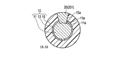
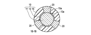
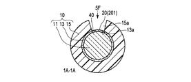
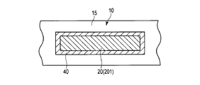
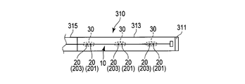
- FIG. 1 is a perspective view of an optical sensor according to a first embodiment of the present invention, a cross-sectional view taken along the line 1A-1A described in the perspective view, and a cross-sectional view taken along the line 1B-1B described in the perspective view. And a sectional view taken along the line 1C-1C described in this perspective view.
- FIG. 2A is a conceptual diagram for detecting two axes.
- FIG. 2B is a conceptual diagram showing that the optical characteristics are light absorption characteristics.
- FIG. 2C is a conceptual diagram showing that the optical characteristics are wavelength conversion characteristics.
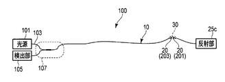
- 3A is a schematic diagram of an optical sensor system having the optical sensor shown in FIG. 1A.
- FIG. 3B is a schematic view of an endoscope having the optical sensor system shown in FIG. 3A.
- FIG. 5C is a diagram illustrating an example of an arrangement position of the characteristic change unit.
- FIG. 5D is a diagram illustrating an example of an arrangement position of the characteristic change unit.
- FIG. 5E is a diagram illustrating the inflow prevention unit.
- FIG. 5F is a view of FIG. 5E as seen from the arrow 5F shown in FIG. 5E.
- FIG. 6A is a diagram illustrating that the optical sensor has a plurality of areas.
- FIG. 6B is a modification of the optical sensor system.
- FIG. 7A is a diagram illustrating a first modification of the optical sensor.
- FIG. 7B is a diagram illustrating a second modification of the optical sensor.
- FIG. 7C is a diagram illustrating a third modification of the optical sensor.
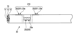
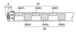
- the tip 201 a of the characteristic changer 201 is arranged closer to the tip of the optical sensor 10 than the tip 203 a of the characteristic changer 203 in the axial direction of the optical sensor 10. It is installed. Further, as shown in the perspective view shown in FIG. 1, the base end portion 201 b of the characteristic changing unit 201 is closer to the optical sensor 10 than the base end portion 203 b of the characteristic changing unit 203 in the axial direction of the optical sensor 10. It is arranged at the tip. As described above, as shown in the cross-sectional view at 1A-1A and the cross-sectional view at 1C-1C shown in FIG.
- the tip 201a of the characteristic changer 201 is the tip 203a of the characteristic changer 203.
- the optical sensor 10 is arranged in a non-overlapping manner in the circumferential direction. Non-overlapping includes non-overlap.
- the tip 201 a of the characteristic changing unit 201 is disposed on the non-same circumference of the optical sensor 10 with respect to the tip 203 a of the characteristic changing unit 203.
- the proximal end portion 201b is disposed at the same position in the axial direction of the optical sensor 10 with respect to the distal end portion 203a, but is disposed at a different position in the circumferential direction of the optical sensor 10. .
- the base end portion 201b of the characteristic changing portion 201 is connected to the base end portion 203b of the characteristic changing portion 203.
- the optical sensor 10 is non-overlapping in the circumferential direction. Non-overlapping includes non-overlap.
- the material A of the characteristic change unit 201 includes the dye A that absorbs light having the wavelength ⁇ 1 in the light propagating through the light guide member 11, and functions as a light absorption unit.
- the material B of the characteristic changing unit 203 has a dye B that absorbs light having a wavelength ⁇ 2 different from the wavelength ⁇ 1 in the light propagating through the light guide member 11, and functions as a light absorbing unit.
- connection connector may be equipped with a feedback system that stabilizes the operation of the light source 101.
- the distal end portion 201a of the characteristic changing portion 201 and the proximal end portion 203b of the characteristic changing portion 203 function as a non-overlapping portion 25a
- the proximal end portion 201b of the characteristic changing portion 201 and the distal end portion 203a of the characteristic changing portion 203 are It functions as the superimposing unit 25b.
- the optical sensor 10 in the optical sensor system 100 may be disposed inside a small precision device (not shown).
- This small precision instrument is, for example, a cylindrical and flexible elongated member such as the insertion portion 310 of the medical endoscope 300 described above, the insertion portion of an industrial endoscope, a manipulator, or a catheter. .
- the entire characteristic changing unit 203 is arranged non-overlapping in the circumferential direction of the optical sensor 10 with respect to the entire characteristic changing unit 201. It can be implemented in a state secured in
- the optical sensor 10 includes the overlapping portion 25b and the non-overlapping portion 25a that sandwich the overlapping portion 25b, which are disposed along the circumferential direction of the optical sensor 10.
Landscapes
- Health & Medical Sciences (AREA)
- Life Sciences & Earth Sciences (AREA)
- Surgery (AREA)
- Physics & Mathematics (AREA)
- Optics & Photonics (AREA)
- Biomedical Technology (AREA)
- Animal Behavior & Ethology (AREA)
- Radiology & Medical Imaging (AREA)
- Nuclear Medicine, Radiotherapy & Molecular Imaging (AREA)
- Engineering & Computer Science (AREA)
- Biophysics (AREA)
- Heart & Thoracic Surgery (AREA)
- Medical Informatics (AREA)
- Molecular Biology (AREA)
- Pathology (AREA)
- General Health & Medical Sciences (AREA)
- Public Health (AREA)
- Veterinary Medicine (AREA)
- General Physics & Mathematics (AREA)
- Endoscopes (AREA)
- Instruments For Viewing The Inside Of Hollow Bodies (AREA)
- Length Measuring Devices By Optical Means (AREA)
Abstract
Selon la présente invention, au moins une partie d'une section (201) de variation de caractéristique est disposée au niveau d'une position différant dans la direction périphérique d'un capteur (10) optique par rapport à au moins une partie d'une section (203) de variation de caractéristique. Également, au moins une partie de la section (201) de variation de caractéristique est disposée au niveau d'une position différant dans la direction axiale du capteur (10) optique par rapport à au moins une partie de la section (203) de variation de caractéristique.
Priority Applications (3)
| Application Number | Priority Date | Filing Date | Title |
|---|---|---|---|
| CN201480043377.3A CN105473980B (zh) | 2013-08-09 | 2014-07-01 | 光学式传感器系统以及具有光学式传感器系统的内窥镜 |
| EP14834390.8A EP3032217A4 (fr) | 2013-08-09 | 2014-07-01 | Capteur optique, système de capteur optique et endoscope |
| US15/018,897 US20160166130A1 (en) | 2013-08-09 | 2016-02-09 | Optical sensor, optical sensor system, and endoscope |
Applications Claiming Priority (2)
| Application Number | Priority Date | Filing Date | Title |
|---|---|---|---|
| JP2013-166882 | 2013-08-09 | ||
| JP2013166882A JP6274775B2 (ja) | 2013-08-09 | 2013-08-09 | 光学式センサシステムと、光学式センサシステムを有する内視鏡 |
Related Child Applications (1)
| Application Number | Title | Priority Date | Filing Date |
|---|---|---|---|
| US15/018,897 Continuation US20160166130A1 (en) | 2013-08-09 | 2016-02-09 | Optical sensor, optical sensor system, and endoscope |
Publications (1)
| Publication Number | Publication Date |
|---|---|
| WO2015019752A1 true WO2015019752A1 (fr) | 2015-02-12 |
Family
ID=52461091
Family Applications (1)
| Application Number | Title | Priority Date | Filing Date |
|---|---|---|---|
| PCT/JP2014/067538 Ceased WO2015019752A1 (fr) | 2013-08-09 | 2014-07-01 | Capteur optique, système de capteur optique et endoscope |
Country Status (5)
| Country | Link |
|---|---|
| US (1) | US20160166130A1 (fr) |
| EP (1) | EP3032217A4 (fr) |
| JP (1) | JP6274775B2 (fr) |
| CN (1) | CN105473980B (fr) |
| WO (1) | WO2015019752A1 (fr) |
Cited By (2)
| Publication number | Priority date | Publication date | Assignee | Title |
|---|---|---|---|---|
| WO2016194059A1 (fr) * | 2015-05-29 | 2016-12-08 | オリンパス株式会社 | Capteur de courbure et dispositif d'endoscope pourvu de celui-ci |
| WO2017009984A1 (fr) * | 2015-07-15 | 2017-01-19 | オリンパス株式会社 | Dispositif de calcul de forme |
Families Citing this family (9)
| Publication number | Priority date | Publication date | Assignee | Title |
|---|---|---|---|---|
| JP6322483B2 (ja) * | 2014-05-29 | 2018-05-09 | オリンパス株式会社 | 曲率センサ、内視鏡装置 |
| JP6278848B2 (ja) * | 2014-06-26 | 2018-02-14 | オリンパス株式会社 | 形状推定装置、それを備えた内視鏡システム及び形状推定のためのプログラム |
| JP6322495B2 (ja) * | 2014-06-26 | 2018-05-09 | オリンパス株式会社 | 形状推定装置、形状推定装置を備えた内視鏡システム及び形状推定のためのプログラム |
| WO2016075831A1 (fr) | 2014-11-14 | 2016-05-19 | オリンパス株式会社 | Dispositif d'estimation d'informations de courbure, système d'endoscope comprenant un dispositif d'estimation d'informations de courbure, procédé d'estimation d'informations de courbure, et programme permettant d'estimer des informations de courbure |
| JP6561134B2 (ja) * | 2015-11-30 | 2019-08-14 | オリンパス株式会社 | 湾曲情報導出装置 |
| DE102016214887A1 (de) * | 2016-08-10 | 2018-02-15 | Fraunhofer-Gesellschaft zur Förderung der angewandten Forschung e.V. | Faseroptischer Sensor sowie Verfahren zu dessen Herstellung und Verwendung |
| CN110999130B (zh) * | 2017-09-07 | 2022-10-28 | 村田机械株式会社 | 有轨台车用光通信系统 |
| EP3857165B1 (fr) * | 2018-09-24 | 2025-03-26 | Fraunhofer-Gesellschaft zur Förderung der angewandten Forschung e.V. | Gant de données et procédé de contrôle d'un programme informatique avec ce gant de données |
| DE102020113731B4 (de) | 2020-05-20 | 2024-02-08 | FiberBridge Photonics GmbH | Glasfaser und Glasfaserprodukt |
Citations (7)
| Publication number | Priority date | Publication date | Assignee | Title |
|---|---|---|---|---|
| JPS57141604A (en) | 1981-02-25 | 1982-09-02 | Canon Inc | Optical fiber |
| JPH08511343A (ja) * | 1993-06-10 | 1996-11-26 | エイ ダニシュ,リー | ファイバオプティック屈曲及び位置決めセンサ |
| JP2004517331A (ja) * | 2001-01-11 | 2004-06-10 | カナディアン・スペース・エージェンシー | 位置形態及び運動測定ツール |
| JP2006288824A (ja) * | 2005-04-12 | 2006-10-26 | Olympus Medical Systems Corp | 電子内視鏡 |
| WO2010113550A1 (fr) * | 2009-03-31 | 2010-10-07 | オリンパスメディカルシステムズ株式会社 | Endoscope |
| WO2013111872A1 (fr) * | 2012-01-25 | 2013-08-01 | オリンパス株式会社 | Capteur en fibre |
| WO2013114963A1 (fr) * | 2012-01-30 | 2013-08-08 | オリンパス株式会社 | Capteur optique |
Family Cites Families (4)
| Publication number | Priority date | Publication date | Assignee | Title |
|---|---|---|---|---|
| CN2490975Y (zh) * | 2001-08-01 | 2002-05-15 | 杭州桐庐尖端内窥镜有限公司 | 便携式电子内窥镜 |
| JP4714570B2 (ja) * | 2005-11-24 | 2011-06-29 | Hoya株式会社 | 内視鏡形状検出プローブ |
| JP2011200410A (ja) * | 2010-03-25 | 2011-10-13 | Fujifilm Corp | キャリブレーション手段を備えた内視鏡システムおよびそのキャリブレーション方法 |
| JP6091052B2 (ja) * | 2011-04-05 | 2017-03-08 | オリンパス株式会社 | 光学式曲がり測定装置 |
-
2013
- 2013-08-09 JP JP2013166882A patent/JP6274775B2/ja active Active
-
2014
- 2014-07-01 EP EP14834390.8A patent/EP3032217A4/fr not_active Withdrawn
- 2014-07-01 WO PCT/JP2014/067538 patent/WO2015019752A1/fr not_active Ceased
- 2014-07-01 CN CN201480043377.3A patent/CN105473980B/zh active Active
-
2016
- 2016-02-09 US US15/018,897 patent/US20160166130A1/en not_active Abandoned
Patent Citations (7)
| Publication number | Priority date | Publication date | Assignee | Title |
|---|---|---|---|---|
| JPS57141604A (en) | 1981-02-25 | 1982-09-02 | Canon Inc | Optical fiber |
| JPH08511343A (ja) * | 1993-06-10 | 1996-11-26 | エイ ダニシュ,リー | ファイバオプティック屈曲及び位置決めセンサ |
| JP2004517331A (ja) * | 2001-01-11 | 2004-06-10 | カナディアン・スペース・エージェンシー | 位置形態及び運動測定ツール |
| JP2006288824A (ja) * | 2005-04-12 | 2006-10-26 | Olympus Medical Systems Corp | 電子内視鏡 |
| WO2010113550A1 (fr) * | 2009-03-31 | 2010-10-07 | オリンパスメディカルシステムズ株式会社 | Endoscope |
| WO2013111872A1 (fr) * | 2012-01-25 | 2013-08-01 | オリンパス株式会社 | Capteur en fibre |
| WO2013114963A1 (fr) * | 2012-01-30 | 2013-08-08 | オリンパス株式会社 | Capteur optique |
Non-Patent Citations (1)
| Title |
|---|
| See also references of EP3032217A4 |
Cited By (8)
| Publication number | Priority date | Publication date | Assignee | Title |
|---|---|---|---|---|
| WO2016194059A1 (fr) * | 2015-05-29 | 2016-12-08 | オリンパス株式会社 | Capteur de courbure et dispositif d'endoscope pourvu de celui-ci |
| CN107613834A (zh) * | 2015-05-29 | 2018-01-19 | 奥林巴斯株式会社 | 曲率传感器和搭载有该曲率传感器的内窥镜装置 |
| JPWO2016194059A1 (ja) * | 2015-05-29 | 2018-03-29 | オリンパス株式会社 | 曲率センサ及びそれを搭載した内視鏡装置 |
| CN107613834B (zh) * | 2015-05-29 | 2019-08-02 | 奥林巴斯株式会社 | 曲率传感器和搭载有该曲率传感器的内窥镜装置 |
| US10842359B2 (en) | 2015-05-29 | 2020-11-24 | Olympus Corporation | Curvature sensor and endoscope apparatus equipped with the same |
| WO2017009984A1 (fr) * | 2015-07-15 | 2017-01-19 | オリンパス株式会社 | Dispositif de calcul de forme |
| CN108024688A (zh) * | 2015-07-15 | 2018-05-11 | 奥林巴斯株式会社 | 形状运算装置 |
| JPWO2017009984A1 (ja) * | 2015-07-15 | 2018-06-07 | オリンパス株式会社 | 形状演算装置 |
Also Published As
| Publication number | Publication date |
|---|---|
| CN105473980B (zh) | 2019-04-23 |
| JP6274775B2 (ja) | 2018-02-07 |
| JP2015034787A (ja) | 2015-02-19 |
| US20160166130A1 (en) | 2016-06-16 |
| EP3032217A4 (fr) | 2017-03-22 |
| EP3032217A1 (fr) | 2016-06-15 |
| CN105473980A (zh) | 2016-04-06 |
Similar Documents
| Publication | Publication Date | Title |
|---|---|---|
| JP6274775B2 (ja) | 光学式センサシステムと、光学式センサシステムを有する内視鏡 | |
| JP6463903B2 (ja) | 内視鏡システム | |
| JP5133595B2 (ja) | 照明光検出用光学系並びにそれを備えた光学装置及び内視鏡装置 | |
| JP6398004B2 (ja) | 曲率センサ及びそれを搭載した内視鏡装置 | |
| JP5963563B2 (ja) | 湾曲センサ | |
| JP6057715B2 (ja) | 光学測定装置およびプローブ装置 | |
| US10307211B2 (en) | Multipoint detection fiber sensor and insertion apparatus including multipoint detection fiber sensor | |
| CN112689482B (zh) | 光探针、医疗用激光探针以及烧灼装置 | |
| JP6322483B2 (ja) | 曲率センサ、内視鏡装置 | |
| US10064542B2 (en) | Bending apparatus with bending direction restriction mechanism | |
| WO2015141636A1 (fr) | Unité optique et système endoscopique | |
| WO2013114963A1 (fr) | Capteur optique | |
| WO2013118553A1 (fr) | Capteur optique | |
| US12279751B2 (en) | Image fiber, endoscope having image fiber, and endoscope system having endoscope | |
| JP2019174256A (ja) | 光ファイバ折れ検知システムおよび光ファイバ折れ検知方法 | |
| WO2017060992A1 (fr) | Dispositif d'éclairage à usage endoscopique | |
| US10111580B2 (en) | Fiber sensor | |
| JP5075524B2 (ja) | 内視鏡装置 | |
| JPWO2017208402A1 (ja) | 形状検出装置 |
Legal Events
| Date | Code | Title | Description |
|---|---|---|---|
| WWE | Wipo information: entry into national phase |
Ref document number: 201480043377.3 Country of ref document: CN |
|
| 121 | Ep: the epo has been informed by wipo that ep was designated in this application |
Ref document number: 14834390 Country of ref document: EP Kind code of ref document: A1 |
|
| NENP | Non-entry into the national phase |
Ref country code: DE |
|
| WWE | Wipo information: entry into national phase |
Ref document number: 2014834390 Country of ref document: EP |