WO2017009984A1 - Dispositif de calcul de forme - Google Patents
Dispositif de calcul de forme Download PDFInfo
- Publication number
- WO2017009984A1 WO2017009984A1 PCT/JP2015/070295 JP2015070295W WO2017009984A1 WO 2017009984 A1 WO2017009984 A1 WO 2017009984A1 JP 2015070295 W JP2015070295 W JP 2015070295W WO 2017009984 A1 WO2017009984 A1 WO 2017009984A1
- Authority
- WO
- WIPO (PCT)
- Prior art keywords
- light
- unit
- photodetector
- setting
- calculation device
- Prior art date
- Legal status (The legal status is an assumption and is not a legal conclusion. Google has not performed a legal analysis and makes no representation as to the accuracy of the status listed.)
- Ceased
Links
Images










Classifications
-
- A—HUMAN NECESSITIES
- A61—MEDICAL OR VETERINARY SCIENCE; HYGIENE
- A61B—DIAGNOSIS; SURGERY; IDENTIFICATION
- A61B1/00—Instruments for performing medical examinations of the interior of cavities or tubes of the body by visual or photographical inspection, e.g. endoscopes; Illuminating arrangements therefor
- A61B1/005—Flexible endoscopes
- A61B1/009—Flexible endoscopes with bending or curvature detection of the insertion part
-
- A—HUMAN NECESSITIES
- A61—MEDICAL OR VETERINARY SCIENCE; HYGIENE
- A61B—DIAGNOSIS; SURGERY; IDENTIFICATION
- A61B1/00—Instruments for performing medical examinations of the interior of cavities or tubes of the body by visual or photographical inspection, e.g. endoscopes; Illuminating arrangements therefor
- A61B1/00002—Operational features of endoscopes
- A61B1/00004—Operational features of endoscopes characterised by electronic signal processing
- A61B1/00006—Operational features of endoscopes characterised by electronic signal processing of control signals
-
- A—HUMAN NECESSITIES
- A61—MEDICAL OR VETERINARY SCIENCE; HYGIENE
- A61B—DIAGNOSIS; SURGERY; IDENTIFICATION
- A61B1/00—Instruments for performing medical examinations of the interior of cavities or tubes of the body by visual or photographical inspection, e.g. endoscopes; Illuminating arrangements therefor
- A61B1/005—Flexible endoscopes
- A61B1/0051—Flexible endoscopes with controlled bending of insertion part
-
- A—HUMAN NECESSITIES
- A61—MEDICAL OR VETERINARY SCIENCE; HYGIENE
- A61B—DIAGNOSIS; SURGERY; IDENTIFICATION
- A61B1/00—Instruments for performing medical examinations of the interior of cavities or tubes of the body by visual or photographical inspection, e.g. endoscopes; Illuminating arrangements therefor
- A61B1/06—Instruments for performing medical examinations of the interior of cavities or tubes of the body by visual or photographical inspection, e.g. endoscopes; Illuminating arrangements therefor with illuminating arrangements
- A61B1/07—Instruments for performing medical examinations of the interior of cavities or tubes of the body by visual or photographical inspection, e.g. endoscopes; Illuminating arrangements therefor with illuminating arrangements using light-conductive means, e.g. optical fibres
-
- A—HUMAN NECESSITIES
- A61—MEDICAL OR VETERINARY SCIENCE; HYGIENE
- A61B—DIAGNOSIS; SURGERY; IDENTIFICATION
- A61B34/00—Computer-aided surgery; Manipulators or robots specially adapted for use in surgery
- A61B34/20—Surgical navigation systems; Devices for tracking or guiding surgical instruments, e.g. for frameless stereotaxis
-
- G—PHYSICS
- G01—MEASURING; TESTING
- G01B—MEASURING LENGTH, THICKNESS OR SIMILAR LINEAR DIMENSIONS; MEASURING ANGLES; MEASURING AREAS; MEASURING IRREGULARITIES OF SURFACES OR CONTOURS
- G01B11/00—Measuring arrangements characterised by the use of optical techniques
- G01B11/16—Measuring arrangements characterised by the use of optical techniques for measuring the deformation in a solid, e.g. optical strain gauge
-
- G—PHYSICS
- G01—MEASURING; TESTING
- G01B—MEASURING LENGTH, THICKNESS OR SIMILAR LINEAR DIMENSIONS; MEASURING ANGLES; MEASURING AREAS; MEASURING IRREGULARITIES OF SURFACES OR CONTOURS
- G01B11/00—Measuring arrangements characterised by the use of optical techniques
- G01B11/16—Measuring arrangements characterised by the use of optical techniques for measuring the deformation in a solid, e.g. optical strain gauge
- G01B11/18—Measuring arrangements characterised by the use of optical techniques for measuring the deformation in a solid, e.g. optical strain gauge using photoelastic elements
-
- G—PHYSICS
- G01—MEASURING; TESTING
- G01D—MEASURING NOT SPECIALLY ADAPTED FOR A SPECIFIC VARIABLE; ARRANGEMENTS FOR MEASURING TWO OR MORE VARIABLES NOT COVERED IN A SINGLE OTHER SUBCLASS; TARIFF METERING APPARATUS; MEASURING OR TESTING NOT OTHERWISE PROVIDED FOR
- G01D5/00—Mechanical means for transferring the output of a sensing member; Means for converting the output of a sensing member to another variable where the form or nature of the sensing member does not constrain the means for converting; Transducers not specially adapted for a specific variable
- G01D5/26—Mechanical means for transferring the output of a sensing member; Means for converting the output of a sensing member to another variable where the form or nature of the sensing member does not constrain the means for converting; Transducers not specially adapted for a specific variable characterised by optical transfer means, i.e. using infrared, visible, or ultraviolet light
- G01D5/32—Mechanical means for transferring the output of a sensing member; Means for converting the output of a sensing member to another variable where the form or nature of the sensing member does not constrain the means for converting; Transducers not specially adapted for a specific variable characterised by optical transfer means, i.e. using infrared, visible, or ultraviolet light with attenuation or whole or partial obturation of beams of light
- G01D5/34—Mechanical means for transferring the output of a sensing member; Means for converting the output of a sensing member to another variable where the form or nature of the sensing member does not constrain the means for converting; Transducers not specially adapted for a specific variable characterised by optical transfer means, i.e. using infrared, visible, or ultraviolet light with attenuation or whole or partial obturation of beams of light the beams of light being detected by photocells
- G01D5/353—Mechanical means for transferring the output of a sensing member; Means for converting the output of a sensing member to another variable where the form or nature of the sensing member does not constrain the means for converting; Transducers not specially adapted for a specific variable characterised by optical transfer means, i.e. using infrared, visible, or ultraviolet light with attenuation or whole or partial obturation of beams of light the beams of light being detected by photocells influencing the transmission properties of an optical fibre
- G01D5/35338—Mechanical means for transferring the output of a sensing member; Means for converting the output of a sensing member to another variable where the form or nature of the sensing member does not constrain the means for converting; Transducers not specially adapted for a specific variable characterised by optical transfer means, i.e. using infrared, visible, or ultraviolet light with attenuation or whole or partial obturation of beams of light the beams of light being detected by photocells influencing the transmission properties of an optical fibre using other arrangements than interferometer arrangements
- G01D5/35341—Sensor working in transmission
- G01D5/35345—Sensor working in transmission using Amplitude variations to detect the measured quantity
-
- G—PHYSICS
- G01—MEASURING; TESTING
- G01D—MEASURING NOT SPECIALLY ADAPTED FOR A SPECIFIC VARIABLE; ARRANGEMENTS FOR MEASURING TWO OR MORE VARIABLES NOT COVERED IN A SINGLE OTHER SUBCLASS; TARIFF METERING APPARATUS; MEASURING OR TESTING NOT OTHERWISE PROVIDED FOR
- G01D5/00—Mechanical means for transferring the output of a sensing member; Means for converting the output of a sensing member to another variable where the form or nature of the sensing member does not constrain the means for converting; Transducers not specially adapted for a specific variable
- G01D5/26—Mechanical means for transferring the output of a sensing member; Means for converting the output of a sensing member to another variable where the form or nature of the sensing member does not constrain the means for converting; Transducers not specially adapted for a specific variable characterised by optical transfer means, i.e. using infrared, visible, or ultraviolet light
- G01D5/32—Mechanical means for transferring the output of a sensing member; Means for converting the output of a sensing member to another variable where the form or nature of the sensing member does not constrain the means for converting; Transducers not specially adapted for a specific variable characterised by optical transfer means, i.e. using infrared, visible, or ultraviolet light with attenuation or whole or partial obturation of beams of light
- G01D5/34—Mechanical means for transferring the output of a sensing member; Means for converting the output of a sensing member to another variable where the form or nature of the sensing member does not constrain the means for converting; Transducers not specially adapted for a specific variable characterised by optical transfer means, i.e. using infrared, visible, or ultraviolet light with attenuation or whole or partial obturation of beams of light the beams of light being detected by photocells
- G01D5/353—Mechanical means for transferring the output of a sensing member; Means for converting the output of a sensing member to another variable where the form or nature of the sensing member does not constrain the means for converting; Transducers not specially adapted for a specific variable characterised by optical transfer means, i.e. using infrared, visible, or ultraviolet light with attenuation or whole or partial obturation of beams of light the beams of light being detected by photocells influencing the transmission properties of an optical fibre
- G01D5/35338—Mechanical means for transferring the output of a sensing member; Means for converting the output of a sensing member to another variable where the form or nature of the sensing member does not constrain the means for converting; Transducers not specially adapted for a specific variable characterised by optical transfer means, i.e. using infrared, visible, or ultraviolet light with attenuation or whole or partial obturation of beams of light the beams of light being detected by photocells influencing the transmission properties of an optical fibre using other arrangements than interferometer arrangements
- G01D5/35341—Sensor working in transmission
- G01D5/35351—Sensor working in transmission using other means to detect the measured quantity
-
- G—PHYSICS
- G01—MEASURING; TESTING
- G01L—MEASURING FORCE, STRESS, TORQUE, WORK, MECHANICAL POWER, MECHANICAL EFFICIENCY, OR FLUID PRESSURE
- G01L1/00—Measuring force or stress, in general
- G01L1/24—Measuring force or stress, in general by measuring variations of optical properties of material when it is stressed, e.g. by photoelastic stress analysis using infrared, visible light, ultraviolet
- G01L1/242—Measuring force or stress, in general by measuring variations of optical properties of material when it is stressed, e.g. by photoelastic stress analysis using infrared, visible light, ultraviolet the material being an optical fibre
- G01L1/246—Measuring force or stress, in general by measuring variations of optical properties of material when it is stressed, e.g. by photoelastic stress analysis using infrared, visible light, ultraviolet the material being an optical fibre using integrated gratings, e.g. Bragg gratings
-
- G—PHYSICS
- G02—OPTICS
- G02B—OPTICAL ELEMENTS, SYSTEMS OR APPARATUS
- G02B6/00—Light guides; Structural details of arrangements comprising light guides and other optical elements, e.g. couplings
- G02B6/02—Optical fibres with cladding with or without a coating
- G02B6/02052—Optical fibres with cladding with or without a coating comprising optical elements other than gratings, e.g. filters
-
- A—HUMAN NECESSITIES
- A61—MEDICAL OR VETERINARY SCIENCE; HYGIENE
- A61B—DIAGNOSIS; SURGERY; IDENTIFICATION
- A61B34/00—Computer-aided surgery; Manipulators or robots specially adapted for use in surgery
- A61B34/20—Surgical navigation systems; Devices for tracking or guiding surgical instruments, e.g. for frameless stereotaxis
- A61B2034/2046—Tracking techniques
- A61B2034/2061—Tracking techniques using shape-sensors, e.g. fiber shape sensors with Bragg gratings
-
- G—PHYSICS
- G02—OPTICS
- G02B—OPTICAL ELEMENTS, SYSTEMS OR APPARATUS
- G02B6/00—Light guides; Structural details of arrangements comprising light guides and other optical elements, e.g. couplings
- G02B6/10—Light guides; Structural details of arrangements comprising light guides and other optical elements, e.g. couplings of the optical waveguide type
- G02B6/14—Mode converters
-
- G—PHYSICS
- G02—OPTICS
- G02B—OPTICAL ELEMENTS, SYSTEMS OR APPARATUS
- G02B6/00—Light guides; Structural details of arrangements comprising light guides and other optical elements, e.g. couplings
- G02B6/24—Coupling light guides
- G02B6/241—Light guide terminations
- G02B6/243—Light guide terminations as light absorbers
Definitions
- the present invention relates to the wavelength acquired using a sensor configured such that the amount of light detected for the wavelength corresponding to each of the plurality of detected parts differs according to the shape of each of the plurality of detected parts, and the above
- the present invention relates to a shape calculation device that calculates the shape of each detected portion from light amount information that is a relationship with the light amount.
- Patent Document 1 discloses an endoscope shape detection probe that bends integrally with a scope and detects the shape of the scope.
- This detection probe has a light modulation part whose light quantity changes according to the curvature as a detected part provided in the fiber for curvature detection.
- the detection probe having such a configuration detects the shape of the scope based on the intensity or wavelength of the light modulated by the light modulation unit and the distance between the light modulation unit and the exit end of the curvature detection fiber. Is possible.
- Patent Document 1 by providing a plurality of detected portions corresponding to different wavelength components in the curvature detection fiber, not only a part of the scope but also various shapes over a desired length can be obtained. It also discloses that it can be detected.
- the generated light amount loss is different. Also, with respect to a detector that detects the amount of light at the exit end of the curvature detection fiber, the sensitivity differs for each wavelength component. For this reason, the light amount can be detected with high accuracy for a certain wavelength component, but the light amount can be detected only with low accuracy for another wavelength component. Therefore, there is a possibility that the shape of each of the plurality of detected parts cannot be accurately calculated.
- Patent Document 1 does not describe any solution to such a problem.
- the present invention has been made in view of the above points, and makes it possible to obtain light amount information, which is a relationship between a wavelength and a light amount, from a sensor having a plurality of detected portions with high accuracy, and thus the shape of each detected portion. It is an object of the present invention to provide a shape calculation device that can accurately calculate.
- One aspect of the shape computing device of the present invention is: The relationship between the wavelength and the amount of light acquired using a sensor configured such that the amount of light detected for a wavelength corresponding to each of the plurality of detected portions differs according to the shape of each of the plurality of detected portions.
- a photodetector for detecting light quantity information A calculation unit that performs calculation related to the shape of each of the plurality of detected units based on the light amount information;
- a setting changing unit that changes the dynamic range of at least one of the intensity of light input to the sensor and the electrical signal generated by the photodetector based on the light output from the sensor; It is characterized by providing.
- a light amount information which is a relationship between a wavelength and a light amount, from a sensor having a plurality of detected portions with high accuracy, and to thereby accurately calculate the shape of each detected portion.
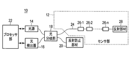
- FIG. 1 is a diagram showing a schematic configuration of a shape computing device according to the first embodiment of the present invention.
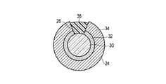
- FIG. 2 is a cross-sectional view of the light conducting member at a portion where the detected portion is provided.
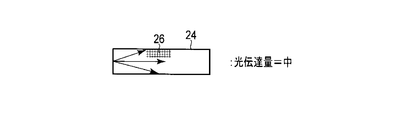
- FIG. 3A is a diagram illustrating a light transmission amount when the light conducting member is not bent.
- FIG. 3B is a diagram illustrating a light transmission amount when the photoconductive member is bent to the side opposite to the side where the detected portion is provided.
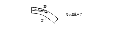
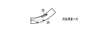
- FIG. 3C is a diagram illustrating the amount of light transmission when the light conducting member is bent to the side where the detected portion is provided.
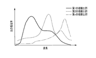
- FIG. 4 is a diagram illustrating an absorption spectrum of light of each detected portion.
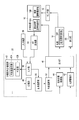
- FIG. 5 is a block diagram illustrating a functional configuration of the processor unit and its peripheral unit of the shape computing device according to the first embodiment.
- FIG. 6 is a diagram illustrating a time chart when the light intensity setting of the light source is sequentially changed in order to sequentially change the dynamic range of the light intensity input to the sensor unit as an example of the variable amount setting change.
- FIG. 7 shows a time chart when the setting of the exposure time of the photodetector is sequentially changed in order to sequentially change the dynamic range of the electrical signal generated by the photodetector as an example of the variable amount setting change.
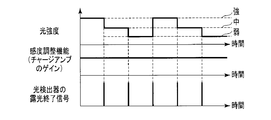
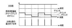
- FIG. 8 is a time chart in the case where the gain setting of the sensitivity of the photodetector is sequentially changed in order to sequentially change the dynamic range of the electric signal generated by the photodetector as an example of the variable amount setting change.
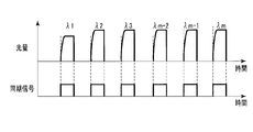
- FIG. 9A is a diagram illustrating detection signals of respective wavelengths acquired by the photodetector in accordance with the constant synchronization signal before the change when the synchronization signal of the photodetector is changed as an example of the variable amount setting change.
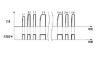
- FIG. 9B shows detection signals for each wavelength acquired by the photodetector according to the synchronization signal after being changed according to the required wavelength when the synchronization signal of the photodetector is changed as an example of changing the variable amount setting.
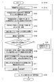
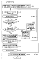
- FIG. 10 is a diagram illustrating an operation flowchart of the shape computing device according to the first embodiment.
- FIG. 11 is a diagram illustrating the relationship between the shape of the light conducting member and the detection signal by the sequential variable amount setting change.
- FIG. 12 is a block diagram showing a functional configuration of the processor unit and its peripheral unit of the shape computing device according to the second embodiment of the present invention.
- FIG. 13 is a diagram illustrating an operation flowchart of the shape computing device according to the second embodiment.
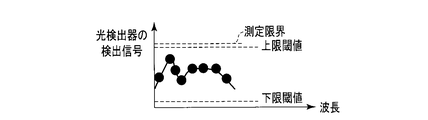
- FIG. 14A is a diagram illustrating the detection signal before the variable amount setting change when the detection signal of the photodetector exceeds the upper limit threshold value.
- FIG. 14B is a diagram illustrating the detection signal after changing the variable amount setting when the detection signal of the photodetector exceeds the upper threshold.
- FIG. 14A is a diagram illustrating the detection signal before the variable amount setting change when the detection signal of the photodetector exceeds the upper limit threshold value.
- FIG. 14B is a diagram illustrating the
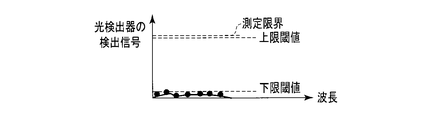
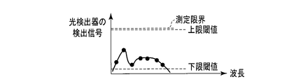
- FIG. 15A is a diagram illustrating a detection signal before the variable amount setting is changed when the detection signal of the photodetector falls below a lower limit threshold value.
- FIG. 15B is a diagram illustrating the detection signal after changing the variable amount setting when the detection signal of the photodetector falls below the lower limit threshold value.
- FIG. 16 is a block diagram illustrating a functional configuration of the processor unit and its peripheral unit of the shape calculation device according to the third embodiment of the present invention.
- FIG. 17 is a diagram illustrating an operation flowchart of the shape calculation apparatus according to the third embodiment.
- FIG. 18A is a diagram illustrating a detection signal before a range change due to a change in the reference voltage of the AD converter as an example of a variable amount setting change.
- FIG. 18A is a diagram illustrating a detection signal before a range change due to a change in the reference voltage of the AD converter as an example of a variable amount setting change.
- FIG. 18B is a diagram illustrating a detection signal after the range is changed by changing the reference voltage of the AD converter as an example of changing the variable amount setting.
- FIG. 19 is a block diagram showing a functional configuration of the processor unit and its peripheral unit of the shape calculation apparatus according to the fourth embodiment of the present invention.
- FIG. 20 is a diagram illustrating an operation flowchart of the shape computing device according to the fourth embodiment.
- FIG. 21A is a diagram illustrating a detection signal before a setting change in an example of obtaining an optimum detection signal by changing a plurality of variable amount settings.
- FIG. 21B is a diagram showing a detection signal after changing the setting of the exposure time of the photodetector from the setting of FIG.
- FIG. 21A in the example of obtaining the optimum detection signal by changing a plurality of variable amount settings.
- FIG. 21C is a diagram illustrating a detection signal after further changing the setting of the exposure time of the photodetector from the setting of FIG. 21B in the example of obtaining the optimum detection signal by changing a plurality of variable amount settings.
- FIG. 21D is a diagram illustrating a detection signal after changing the setting of the light intensity of the light source from the setting of FIG. 21C in the example of obtaining the optimum detection signal by changing a plurality of variable amount settings.
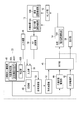
- FIG. 22 is a block diagram illustrating a schematic configuration of an endoscope apparatus in which the shape calculation device according to any of the embodiments is mounted.
- the shape calculation device 10 includes a sensor unit 12, a light source 14, a photodetector 16, a light branching unit 18, an antireflection member 20, and a processor unit 22. And.
- the sensor unit 12 includes a light conducting member 24 and n detected portions 26 (first detected portion 26-1, second detected portion 26-2,..., Nth detected portion 26-n. ) And the reflecting member 28.
- the light source 14 can use light from a laser diode (LD), an LED, a lamp, or the like, or light obtained by emitting a fluorescent material using these lights.
- the light (for example, white light) is adjusted and emitted.
- the light branching unit 18 is constituted by, for example, a fiber coupler, a half mirror, or a beam splitter, and makes the light emitted from the light source 14 enter one end of the light conducting member 24.
- the optical branching unit 18 is a fiber coupler
- the light source 14 includes a lens system that collects light and enters the fiber of the fiber coupler.
- the light branching unit 18 is a half mirror or a beam splitter
- the light source 14 includes a lens system that adjusts the light into parallel light.
- the light source 14 includes an isolator or the like.
- the light conducting member 24 guides the light incident on the one end by the light branching portion 18 to the other end and emits the light from the other end.
- the reflecting member 28 reflects the light emitted from the other end of the light conducting member 24 and makes it enter the other end of the light conducting member 24 again. Thereby, the light conducting member 24 guides the light incident on the other end to the one end and emits the light from the one end.
- the light branching unit 18 inputs light emitted from one end of the light conducting member 24 to the photodetector 16.
- the photodetector 16 detects the light amount of a predetermined wavelength from the input light, and outputs light amount information that is a relationship between the wavelength and the light amount to the processor unit 22.
- the antireflection member 20 is used to prevent light that has not been incident on the photoconductive member 24 from returning to the photodetector 16.
- the light conducting member 24 is arranged to extend along the longitudinal axis direction of a structure, for example, an insertion portion of an endoscope, whose curvature information is to be detected by the shape computing device 10, and the curved state of the structure. It has the flexibility to bend following the above.
- the light conducting member 24 can be constituted by an optical fiber.
- FIG. 2 shows a cross-sectional structure in the radial direction that is a direction orthogonal to the longitudinal axis direction of the optical fiber. That is, the optical fiber includes a core 30 that guides light at the center, a clad 32 that is provided around the core 30 and stably traps light in the core 30, and the core 30 and the clad. And a jacket 34 for protecting 32 from physical and thermal shocks.
- the light conducting member 24 is not limited to an optical fiber, and may be constituted by an optical waveguide.
- the photoconductive member 24 has a detected portion 26 (a first detected portion 26-1, a first detected portion 26-1, a light absorption spectrum different from each other) at a position corresponding to each position of the structure where the curvature information is to be detected.
- Second detected portions 26-2,..., Nth detected portions 26-n) are provided.
- the curvature information is information on a bending direction and a bending magnitude.
- FIG. 3A shows the light transmission amount when the light conducting member 24 is not bent
- FIG. 3B shows the light conducting member 24 bent to the side opposite to the side where the detected portion 26 is provided
- 3C shows the light transmission amount when the light conducting member 24 is bent to the side where the detected portion 26 is provided.
- the light transmission amount is the largest when the light conducting member 24 is bent to the side where the detected portion 26 is provided.
- the detected portion 26 removes the jacket 34 and the clad 32 at a desired position in the longitudinal axis direction of the light conducting member 24 to expose a part of the core 30.
- the exposed portion of the core 30 has an optical effect different from that of the other detected portions 26 on the spectrum of light incident on the core 30 according to the amount of bending in a specific direction.
- the detected member 36 made of a member is formed to a thickness such that the original shape of the photoconductive member 24 is recovered.
- the detected member 36 is made of a flexible member or an elastic material, for example, a low refractive index material such as an acrylic, epoxy, silicon, or fluorine resin, or soft water glass.
- the detected member 36 is formed to have a thickness of about a clad thickness, and a portion of the detected member 36 from which the jacket 34 and the clad 32 are removed is filled with a jacket-like member, so that light conduction is achieved.
- the original shape of the member 24 may be recovered.
- the jacket 34 and the clad 32 are removed by laser processing or using a photo process, an etching process, and the like. At this time, if the core 30 is micro-scratched, light is leaked and light to be guided is lost or bending is weak. Therefore, the core 30 is not scratched as much as possible. It is desirable to process by the method.
- each detected portion 26 can be a light absorber having a different light absorption spectrum as shown in FIG. That is, in each detected portion 26, if a predetermined wavelength region is absorbed, and the amount of light of the wavelength is detected, the amount of curvature of the detected portion 26 can be obtained based on the amount of light.
- the detected member 36 may be constituted by an optical property changing member made of metal particles that absorbs light in a predetermined wavelength range.
- the optical property changing member made of the metal particles has a special spectral absorption spectrum different from the spectral absorption spectrum unique to the metal.
- the optical property changing member made of the metal particles has a light excitation plasmon generation function capable of exciting plasmons with light of at least one kind of light source. That is, it is a metal nanoparticle having the sum of a spectral absorption spectrum unique to a metal and a special absorption spectrum due to the surface plasmon effect as an absorption spectrum.
- the photoexcited plasmon generation function is configured by at least one kind of plasmon substance, nanosized substance, nanosized mineral, or nanosized metal.
- the plasmon substance is a substance having a state in which free electrons collectively vibrate and behave as pseudo particles.
- the nano size means smaller than 1 ⁇ m.
- the metal particles are, for example, Au, Ag, Cu, Pt, etc., and are a dispersion medium.
- the shape of the metal particles is a sphere, a cylinder, or a polygonal column.
- the photo-excited plasmon generation function has different special spectral absorption spectra if at least one of the size, length, and thickness of the same optical property changing member, for example, the same metal particle, is different. For example, as the particle size increases, the peak wavelength of absorption of light (absorption wavelength characteristic region) moves to the longer wavelength side. Therefore, the plurality of detected parts 26 have combinations having different special spectral absorption spectra with the same metal element as the optical property changing member.
- the photoexcited plasmon generation function differs in the special spectral absorption spectrum of another optical property changing member, for example, another metal particle.
- a composite optical property changing member in which a plurality of metal particles are mixed may be used.
- the detected member 36 having different special spectral absorption spectra. Therefore, it is possible to form a large number of detected portions 26 that give different optical characteristic changes from other detected portions 26.
- the optical property changing member may be, for example, an optical property changing member having a laminated dielectric film, an optical property changing member having a phosphor, an optical property changing member having a grating structure, and the like.
- the shape calculation device 10 configured as described above, light is incident on the light conducting member 24 from the light source 14 through the light branching portion 18.
- the incident light is reflected from the reflecting member 28 at the tip of the light conducting member 24.
- the reflected light is received by the photodetector 16 through the light branching unit 18.
- the light received by the photodetector 16 has passed through the detected part 26 (first detected part 26-1, second detected part 26-2,..., Nth detected part 26-n). It is light and varies depending on the curvature of the photoconductive member 24.
- the light quantity of the wavelength related to each detected part 26 received by the photodetector 16 is given to the processor section 22 as light quantity information (D ⁇ n), and the processor section 22 calculates curvature information based on this light quantity information.
- the light source 14 can include a current adjustment function unit 14 ⁇ / b> A that changes the intensity of emitted light.
- the photodetector 16 can include an exposure time adjustment function unit 16A that changes the exposure time.
- the photodetector 16 can include a sensitivity adjustment function unit 16B that changes the sensitivity by changing the gain setting of a charge amplifier circuit (not shown) of the photodetector 16. Details of these functions will be described later.
- the processor unit 22 includes an input unit 38, a resolution improving function unit 40, a light source driving unit 42, a photodetector driving unit 44, an output unit 46, a storage unit 48, a curvature calculating unit 50, and a shape. And an arithmetic unit 52.
- the processor unit 22 can be configured by a computer, for example.
- the input unit 38 receives input data given from the outside of the processor unit 22 and supplies it appropriately to the resolution improving function unit 40 and the curvature calculating unit 50. Specifically, the detection signal of each wavelength of the sensor unit 12 converted into digital data by the AD converter 54 from the photodetector 16 is input to the input unit 38. Further, an exposure end signal is also input to the input unit 38 from the photodetector 16. In addition, a curvature derivation start signal, a curvature derivation end signal, sensor identification information, a signal related to the setting of the curvature calculator 50, and the like are input to the input unit 38 from the input device 56. Input device 56 includes a switch or button for instructing the start / end of curvature derivation.
- a keyboard for setting the type of the sensor unit 12 and the setting of the curvature calculation unit 50 by inputting information to the menus and selection items displayed on the display unit 58 is included.
- a communication device that inputs information from the outside via a wireless or wired network can also be included.
- the resolution enhancement function unit 40 changes the dynamic range of one of the intensity of light input to the sensor unit 12 and the electrical signal generated by the photodetector 16 based on the light output from the sensor unit 12. Thus, the function of improving the resolution of the light quantity information is achieved.
- the resolution improving function unit 40 detects the light intensity by the current adjustment function unit 14 ⁇ / b> A of the light source 14 and the exposure time adjustment function unit 16 ⁇ / b> A of the light detector 16.
- variable amount setting unit 40A changes the dynamic range in stages by changing the settings in stages. Further, the variable amount setting unit 40A performs the stepwise change every time the input unit 38 acquires an exposure end signal from the photodetector 16, thereby performing a sequential setting change.
- variable amount setting unit 40A determines how many steps of the X-step step setting to the light source driving unit 42 or the photodetector driving unit 44 by the variable amount setting unit 40A. This is done by sending an order signal to represent.
- variable amount setting unit 40A can transmit an order signal to the light source driving unit 42.
- the light source driving unit 42 changes the set light intensity information based on the transmitted order signal. Then, the light source driving unit 42 transmits information on the light intensity newly set by this change to the current adjustment function unit 14 ⁇ / b> A of the light source 14 through the output unit 46.
- the current adjustment function unit 14 ⁇ / b> A can adjust the intensity of light input to the sensor unit 12 by driving the LD or the like with a drive current according to the light intensity information from the light source driving unit 42.
- the exposure time and the gain setting of the charge amplifier circuit are not adjusted at all, and the exposure end signal acquired by the input unit 38 from the photodetector 16 is It is acquired at a constant period, and the sensitivity of the photodetector 16 is also constant regardless of time.
- variable amount setting unit 40A can transmit an order signal to the photodetector driving unit 44.
- the photo detector drive unit 44 associates the exposure time with the order signal so as to change the information of the set exposure time based on the transmitted order signal.
- the photodetector drive unit 44 transmits information on the exposure time newly set by this change to the exposure time adjustment function unit 16 ⁇ / b> A of the photodetector 16 through the output unit 46.
- the exposure time adjustment function unit 16A detects the detection signal of each wavelength from the sensor unit 12 with the exposure time according to the exposure time information from the photodetector drive unit 44, and outputs from the sensor unit 12.
- the electrical signal generated by the photodetector 16 can be adjusted based on the emitted light.
- the variable amount setting unit 40A sequentially drives the order signal to the photodetector so that the exposure time is sequentially changed in three stages: “order number 3: short” ⁇ “order number 1: long” ⁇ .
- the exposure end signal acquired by the input unit 38 from the photodetector 16 does not have a constant period, but changes with time.
- the order signal is not output to the light source driving unit 42, the intensity of the light emitted from the light source 14 is constant regardless of the time.
- the gain setting of the charge amplifier circuit of the photodetector 16 is not associated with the order signal, so the sensitivity of the photodetector 16 is also constant regardless of time.
- variable amount setting unit 40A can transmit an order signal to the photodetector driving unit 44.
- the photodetector driving unit 44 associates the gain setting of the charge amplifier circuit with the order signal so as to change the information of the gain setting of the set charge amplifier circuit based on the transmitted order signal. Yes.
- the photodetector drive unit 44 outputs the gain setting information of the charge amplifier circuit newly set by this change to the sensitivity adjustment function unit 16B of the photodetector 16 through the output unit 46.
- the sensitivity adjustment function unit 16 ⁇ / b> B detects the detection signal of each wavelength from the sensor unit 12 with the sensitivity according to the gain setting information of the charge amplifier circuit from the photodetector driving unit 44, thereby detecting the sensor unit 12.
- the electrical signal generated by the light detector 16 can be adjusted based on the light output from.
- the input unit 38 ends the exposure from the photodetector 16 as shown in the time chart of FIG. Every time a signal is acquired, “Sequence number 1: Gain high” ⁇ “Sequence number 2: Medium gain” ⁇ “Sequence number 3: Gain low” ⁇ “Sequence number 1: Gain high” ⁇ ...
- the variable amount setting unit 40A sequentially sets the order signal to the photodetector driving unit 44 so that the change is performed sequentially.
- the exposure time is not associated with the sequence number in the photodetector driving unit 44, the exposure time is not adjusted at all, and the exposure end signal acquired by the input unit 38 from the photodetector 16 is: It is acquired at a constant cycle.
- the turn signal is not output to the light source driving unit 42, the intensity of the light emitted from the light source 14 is constant regardless of time.
- the association of the exposure time of the photodetector 16 or the sensitivity of the photodetector 16 with the order signal in the photodetector driving unit 44 is performed in advance at the time of shipment from the factory. Alternatively, the association may be changed based on sensor identification information input from the input device 56 to the input unit 38.
- variable amount setting unit 40A transmits the order signal to the light source driving unit 42 or the photodetector driving unit 44 may be performed in advance at the time of shipment from the factory or from the input device 56 to the input unit 38. The selection may be made based on the sensor identification information input to.
- the storage unit 48 stores in advance curvature characteristic information corresponding to various settings of the photodetector 16 and the light source 14 for each type of usable sensor unit 12.
- the curvature calculation unit 50 corresponds to optimal light amount information (details will be described later) in the detection signal corresponding to the adjustment acquired by the input unit 38 and sensor identification information input from the input device 56 to the input unit 38. Based on the curvature characteristic information corresponding to various settings of the photodetector 16 and the light source 14 stored in the storage unit 48, each detected unit 26 (first detected unit 26-1, The curvature information of the second detected portion 26-2,..., The nth detected portion 26-n) is calculated. The curvature calculation unit 50 transmits the calculated curvature information of each detected unit 26 to the shape calculation unit 52.
- the shape calculation unit 52 converts the curvature information of each detected portion 26 into shape information of a structure such as an insertion portion of an endoscope.
- the shape calculation unit 52 transmits the shape information of the structure to the display unit 58 through the output unit 46.
- the display unit 58 displays the shape information of the structure.
- the photodetector 16 as shown in FIG. 9A, a type in which the detection wavelength, that is, the wavelength to be exposed is switched according to the synchronization signal may be used.
- this type of photodetector 16 when the exposure time is changed stepwise by the exposure time adjustment function unit 16A, all wavelengths ( ⁇ 1 to ⁇ m: m within the changed exposure time). It is necessary to adjust the period (frequency) of the synchronization signal so that> n) is exposed.
- the wavelengths used for the plurality of detected portions 26 of the sensor unit 12 that is, the wavelengths used for the curvature calculation
- the photodetector driving unit 44 is configured so that a variable synchronization signal corresponding to such a wavelength is supplied from the output unit 46 to the photodetector 16.
- the setting information of the synchronization signal can also be changed.
- such a change of the synchronization signal is not limited to the case where the exposure time information is set to “short”, but is always performed when the sequential X-stage change is performed as in the present embodiment. Also good. If a sequential change as described above, for example, a three-stage change is made, it takes three times longer to obtain the light amount information used by the processor unit 22 for the curvature calculation than when no change is made. It will be. By varying the synchronization signal in accordance with the wavelength range to be used, it is possible to reduce the total light amount information acquisition time required for one curvature calculation.
- the resolution improving function unit 40 transmits the order signal to the light source driving unit 42 or the photodetector driving unit 44 by the variable amount setting unit 40A (step S102).
- the light source driving unit 42 or the photodetector driving unit 44 that has received the order signal changes the setting of the light source driving unit 42 or the photodetector driving unit 44 based on the order signal from the variable amount setting unit 40A.
- the set information is transmitted to the light source 14 or the photodetector 16 through the output unit 46 (step S104). Thereby, the setting of the light intensity, exposure time, or sensitivity corresponding to the sequence number is changed.
- step S105 After the setting is changed in this way, light emission from the light source 14 is started, and the light detector 16 starts detecting the light amount of each wavelength in the light from the sensor unit 12 (step S105).
- the detected light quantity information is input to the input unit 38 via the AD converter 54.
- the input light amount information is temporarily stored in a memory (not shown) configured in the input unit 38. Alternatively, the light amount information may be supplied from the input unit 38 to the storage unit 48 and stored therein.
- routine A consisting of steps S102 to S108 is repeated.
- the light quantity information is detected with the light intensity, the exposure time, or the sensitivity set by the setting information of the X stage.
- the setting information of light intensity, exposure time, or sensitivity includes the light conducting member 24 with a small light transmission amount as shown in FIG. 3B.
- the maximum value of the detection signal of the light detector 16 is set to a value that almost becomes the measurement limit of the light detector 16 when it is curved to the side opposite to the side where the detection unit 26 is provided. Therefore, even in such a curved state, the light amount of the wavelength corresponding to each detected portion 26 can be detected, and the light amount information of all the detected portions 26 can be acquired with high resolution.
- the black circles indicate the light amount information acquired corresponding to each detected unit 26.
- the setting information of the light intensity, the exposure time, or the sensitivity is such that when the light conducting member 24 having a medium light transmission amount as shown in FIG.
- the maximum value of the detection signal of the photodetector 16 is set to a value that almost becomes the measurement limit of the photodetector 16.
- the light quantity information that cannot be acquired due to overshooting with the settings of sequential 1 and 2 can be acquired with high resolution.
- the curvature calculation unit 50 selects the optimum light amount information used for the curvature calculation from the light amount information in the plurality of (X stage) setting information acquired from the photodetector 16 (step S109).
- the curvature calculation unit 50 selects them as the optimum light quantity information used for the curvature calculation.
- the curvature calculating unit 50 acquires the light amount information acquired by the sequential 2 for the light amount information of the detected portion 26. Select.
- the curvature calculating unit 50 acquired the light amount information of the detected portion 26 with the sequential 3. Select light intensity information. In this way, the curvature calculation unit 50 selects the optimal (largest) light amount information that does not overshoot. Or you may decide beforehand which detection signal of sequential 1 thru
- the curvature calculation unit 50 acquires the curvature characteristic information of the sensor unit 12 with the selected light amount information to be used from the storage unit 48, and calculates the curvature of the detected unit 26 (step S110). That is, since the curvature characteristic information differs depending on whether each light quantity information to be used is sequential 1 to 3, the curvature characteristic information corresponding to each light quantity information is acquired, and the detected portion 26 corresponding to each light quantity information is obtained. The curvature will be calculated.
- the shape calculating unit 52 creates the shape of the structure based on the curvature of the detected unit 26 calculated by the curvature calculating unit 50 and the position information of the detected unit 26 as foresight information (step S111). And the shape calculating part 52 displays the shape of this created structure on the display part 58 via the output part 46 (step S112).
- step S101 is repeated.
- routine B consisting of steps S101 to S112 is repeated.
- the shape of the structure according to the displacement of the structure can be updated and displayed on the display unit 58.
- step S120 When the input unit 38 receives a curvature derivation end signal from the input device 56 during execution of the routine A or the routine B as described above (step S120), the processing of this flowchart is ended.
- the amount of light detected for the wavelength corresponding to each of the plurality of detected units 26 varies depending on the shape of each of the plurality of detected units 26.
- the light detector 16 that detects light amount information that is a relationship between the wavelength and the light amount acquired by using the sensor unit 12 that is configured as described above, and an operation related to the shape of each of the plurality of detected portions 26 based on the light amount information.
- the curvature calculation unit 50 to perform, the intensity of light input to the sensor unit 12, and the detection signal of the photodetector 16 which is an electrical signal generated by the photodetector 16 based on the light output from the sensor unit 12.
- a setting changing unit for changing one of the dynamic ranges.
- the setting change unit includes the light source driving unit 42 and the current adjustment function unit 14A of the light source 14, the photodetector driving unit 44, and the photodetector 16. It includes any one of the exposure time adjustment function unit 16A, the photodetector drive unit 44, and the sensitivity adjustment function unit 16B of the photodetector 16.
- Such a shape calculation device 10 changes the dynamic range of one of the intensity of light input to the sensor unit 12 and the electrical signal generated by the photodetector 16 based on the light output from the sensor unit 12. By doing so, it becomes possible to acquire light amount information, which is a relationship between the wavelength and the light amount, from the sensor unit 12 having the plurality of detected portions 26 with high accuracy, so that the shape of each detected portion 26 can be accurately determined. It can be calculated.
- variable amount setting unit 40A, the photodetector driving unit 44 of the resolution improving function unit 40, and the exposure time adjusting function unit 16A of the photodetector 16 can detect light by changing the exposure time of the photodetector 16.
- the dynamic range of the detection signal of the detector 16 can be changed.
- variable amount setting unit 40A and the photodetector driving unit 44 change the dynamic range of the detection signal of the photodetector 16 by changing the frequency of the synchronization signal related to the detection of the photodetector 16. Also good.
- variable amount setting unit 40A, the photodetector driving unit 44, and the sensitivity adjustment function unit 16B of the photodetector 16 change the detection sensitivity of the photodetector 16, thereby dynamically changing the detection signal of the photodetector 16.
- the range can be changed.
- variable amount setting unit 40A, the light source drive unit 42, and the current adjustment function unit 14A of the light source 14 change the light intensity input to the sensor unit 12, thereby changing the dynamic range of the intensity of light input to the sensor unit. Can be changed.
- the shape calculation apparatus 10 can further include an input device 56 as an instruction unit that instructs a method to be used among these dynamic range changing methods.
- the shape calculation device 10 can change the dynamic range step by step, and can make this step change sequentially.
- the shape calculation device 10 can further include a light source 14 that emits light and the sensor unit 12.
- the sensor unit 12 includes a plurality of detection targets including a light conducting member 24 that is a light guide member that guides light emitted from the light source 14 and an optical property changing member provided in the light conducting member 24.
- a plurality of detected portions 26 each including a plurality of detected members 36 that are members 36 and have different influences on the spectrum of light guided by the light conducting member 24.
- the photodetector 16 detects light that is guided by the light conducting member 24 and is influenced by the plurality of detected members 36, and outputs light amount information.
- the light intensity of the light source 14, the exposure time of the photodetector 16, so that the magnitude of the detection signal of the photodetector 16 changes stepwise according to the exposure end signal Alternatively, the sensitivity setting of the photodetector 16 is changed sequentially according to the exposure end signal.
- the light intensity of the light source 14, the exposure time of the light detector 16, or the sensitivity of the light detector 16 is set as the detection signal of the light detector 16.
- the state is changed after determining the state of the size.
- the shape calculation device 10 determines whether or not the resolution improvement function unit 40 of the processor unit 22 changes the dynamic range in addition to the variable amount setting unit 40A.
- the determination unit 40B is further provided, and the variable amount setting unit 40A operates according to the determination of the determination unit 40B.
- the determination unit 40B determines that the detection signal is not within the detectable range by comparing the detection signal of the photodetector 16 with a threshold value regarding the lower limit of detection (lower limit threshold value) and a threshold value regarding the upper limit of detection (upper limit threshold value). When it is determined that the dynamic range is changed.
- the upper limit threshold and the lower limit threshold for use in the determination unit 40B are stored in the storage unit 48 in advance.
- the upper limit threshold and the lower limit threshold may be input from the input device 56 and stored in the storage unit 48. That is, the input device 56 can be used as an instruction unit for instructing change of information related to the determination by the determination unit 40B.
- the resolution improving function unit 40 starts from the variable amount setting unit 40A to the light source driving unit 42 or the photodetector driving unit 44. Is transmitted to the determination unit 40B by reading out information on the upper and lower thresholds from the storage unit 48 (step S201). According to the initial setting from the variable amount setting unit 40A, the light source driving unit 42 or the photodetector driving unit 44 changes the setting of the light source driving unit 42 or the photodetector driving unit 44 and outputs the set information. The light is transmitted to the light source 14 or the photodetector 16 through the unit 46.
- the setting of light intensity, exposure time, or sensitivity is set to an initial state.
- the initial set value of the light intensity, exposure time, or sensitivity is not particularly limited.
- the variable amount setting unit 40A instructs the light source driving unit 42 or the photodetector driving unit 44 to set the sequential 2 in the first embodiment.
- Sequential 2 can be set by transmitting the sequence number to be transmitted.
- the setting information according to the setting information can be changed by directly transmitting the setting information itself of the light intensity, the exposure time, or the sensitivity from the variable amount setting unit 40A to the light source driving unit 42 or the photodetector driving unit 44. You may be made to be.
- step S105 emission of light from the light source 14 is started, and the photodetector 16 starts detecting the light amount of each wavelength in the light from the sensor unit 12 (step S105).
- the detected light quantity information is input to the input unit 38 via the AD converter 54 and is stored in a memory (not shown) configured in the input unit 38 or the storage unit 48.
- the light detector 16 outputs an exposure end signal when it has detected the light amounts of all wavelengths ( ⁇ 1 to ⁇ m). Therefore, when the input unit 38 receives this exposure end signal from the photodetector 16 (step S106), the determination unit 40B of the resolution enhancement function unit 40 determines whether or not the detection signal from the photodetector 16 exceeds the upper limit threshold value. Is determined (step S202).
- the upper threshold value is preferably a value slightly smaller than the measurement limit of the photodetector 16. The determination by the determination unit 40B may be performed for all wavelengths of the detection signal of the photodetector 16, or may be performed only for one or a plurality of specific wavelengths specified in advance.
- the determination unit 40B outputs information indicating that to the variable amount setting unit 40A.
- variable amount setting unit 40A When receiving information indicating that one of the light quantity information used for the curvature calculation exceeds the upper threshold, the variable amount setting unit 40A reduces the detection signal of the photodetector 16 as shown in FIG. 14B. Then, the setting of the light source 14 or the photodetector 16 is changed (step S203). That is, the variable amount setting unit 40A sets the settings of the current adjustment function unit 14A of the light source 14 or the exposure time adjustment function unit 16A of the photodetector 16 or the sensitivity adjustment function unit 16B of the photodetector 16 to the photodetector 16. A sequence number or setting information for changing the detection signal to be small is transmitted to the light source driving unit 42 or the photodetector driving unit 44. Then, the operation returns to the process of step S105.
- step S203 not only the setting of the light source 14 or the photodetector 16 may be changed, but the upper threshold value that is the determination criterion of the determination unit 40B may be changed. That is, the threshold value can be changed to the optimum upper limit threshold for the detection signal of the photodetector 16 after the setting is changed.
- routine A consisting of step S105, step S106, step S202, and step S203 can be repeated. That is, the current adjustment function unit 14A of the light source 14, the exposure time adjustment function unit 16A of the light detector 16, or the sensitivity so that the detection signal of the light detector 16 becomes smaller when the upper limit threshold is exceeded even after the setting is changed.
- the setting of the adjustment function unit 16B is changed through the light source 14 or the photodetector driving unit 44. As described above, the current adjustment function unit 14A of the light source 14, the exposure time adjustment function unit 16A of the light detector 16, or the sensitivity adjustment function of the light detector 16 so that the detection signal of the light detector 16 can be acquired with an optimum setting.
- the setting of the unit 16B can be changed step by step.
- the determination unit 40B determines in step S202 that the detection signal from the photodetector 16 does not exceed the upper limit threshold, the determination unit 40B further receives the detection signal from the photodetector 16. It is determined whether or not it is smaller than the lower limit threshold (step S204). Note that the determination by the determination unit 40B may be performed for all wavelengths of the detection signal of the photodetector 16 as in the case of the determination for the upper threshold, or one or a plurality of specific wavelengths specified in advance. You may make it only about.
- the determination unit 40B sends information indicating that to the variable amount setting unit 40A. Output.
- the variable amount setting unit 40A changes the setting of the light source 14 or the photodetector 16 so that the detection signal of the photodetector 16 becomes large as shown in FIG. 15B (step S205). That is, the variable amount setting unit 40A sets the settings of the current adjustment function unit 14A of the light source 14, the exposure time adjustment function unit 16A of the photodetector 16, or the sensitivity adjustment function unit 16B of the photodetector 16 to the photodetector 16.
- a sequence number or setting information for changing the detection signal so as to increase is transmitted to the light source driving unit 42 or the photodetector driving unit 44.
- the setting signal is changed so that the detection signal of the photodetector 16 becomes smaller in step S203, the detection signal of the photodetector 16 becomes lower than the lower limit threshold.
- the setting of the light source 14 or the photodetector 16 can be changed so as to return to the setting. Then, the operation returns to the process of step S105.
- step S205 not only the setting of the light source 14 or the light detector 16 may be changed, but also the lower limit threshold that is the determination criterion of the determination unit 40B may be changed. That is, the threshold value can be changed to the optimum lower limit threshold for the detection signal of the photodetector 16 after the setting is changed.
- the routine B consisting of step S105, step S106, step S202, step S204, and step S205 can be repeated. That is, the current adjustment function unit 14A of the light source 14, the exposure time adjustment function unit 16A of the light detector 16, or the sensitivity so that the detection signal of the light detector 16 becomes larger when the value falls below the lower limit threshold even after the setting is changed.
- the setting of the adjustment function unit 16B is changed through the light source driving unit 42 or the photodetector driving unit 44. As described above, the current adjustment function unit 14A of the light source 14, the exposure time adjustment function unit 16A of the light detector 16, or the sensitivity adjustment function of the light detector 16 so that the detection signal of the light detector 16 can be acquired with an optimum setting.
- the setting of the unit 16B can be changed step by step.
- step S202 the determination unit 40B determines that the detection signal from the photodetector 16 does not exceed the upper limit threshold value, and in step S204, the determination unit 40B detects from the photodetector 16. If it is determined that the signal is not below the lower limit threshold, the curvature calculation unit 50 acquires curvature characteristic information according to the settings of the light source 14 and the photodetector 16 from the storage unit 48 (step S206). That is, the curvature calculation unit 50 adjusts the sensitivity of the current adjustment function unit 14A of the light source 14 from the variable amount setting unit 40A of the resolution improvement function unit 40, the exposure time adjustment function unit 16A of the photodetector 16, or the sensitivity of the photodetector 16.
- Curvature characteristic information based on the setting information of the function unit 16B is acquired from the storage unit 48. Then, the curvature calculation unit 50 calculates the curvature of each detected unit 26 based on the acquired detection signal of the photodetector 16 and this curvature characteristic information (step S207).
- step S111 The subsequent process of creating the shape of the structure in step S111 and the process of displaying the shape in step S112 are the same as in the first embodiment.
- step S105 Thereafter, the operation from step S105 is repeated.
- routine C consisting of steps S105 to S112 is repeated.
- the shape of the structure according to the displacement of the structure can be updated and displayed on the display unit 58.
- step S220 When the input unit 38 receives a curvature derivation end signal from the input device 56 during execution of the routine A, routine B or routine C as described above (step S220), the processing of this flowchart is ended.
- the sensor unit 12 is changed by changing any of the light intensity input to the sensor unit 12, the exposure time of the photodetector 16, and the detection sensitivity of the photodetector 16.
- the dynamic range of one of the intensity of the input light and the electrical signal generated by the photodetector 16 based on the light output from the sensor unit 12 is changed. That is, the first embodiment is characterized in that the resolution improving function unit 40 intervenes before or when the light detector 16 converts the light amount into an electric signal.
- the shape calculation device 10 is characterized in that the resolution improving function unit 40 intervenes after converting the light amount into an electrical signal. That is, by changing the range of the detection signal from the photodetector 16, the dynamic range of the electrical signal generated by the photodetector 16 based on the light output from the sensor unit 12 is changed. More specifically, a change related to digital conversion of the electric signal is performed.
- the shape calculation device 10 includes a ⁇ side reference voltage and a + side reference voltage of the AD converter 54 that converts the light amount information from the photodetector 16 into digital data.
- AD converter driving unit 60 in the processor unit 22 for outputting reference voltage data indicating the D / A and DA conversion for converting the reference voltage data into a ⁇ side reference voltage REF ⁇ and a + side reference voltage REF + and applying the converted voltage to the AD converter 54 And a device 62.
- the variable amount setting unit 40A of the resolution improving function unit 40 transmits a command value indicating how to use the reference voltage data to the AD converter driving unit 60.
- the AD converter 54 performs digital conversion of the light amount information in the range of the applied ⁇ side reference voltage REF ⁇ and + side reference voltage REF +.
- the resolution improving function unit 40 starts from the variable amount setting unit 40A to the reference of the AD converter 54 from the variable amount setting unit.
- the voltage setting is transmitted to the AD converter 54 as an initial setting (step S301). That is, as shown in FIG. 18A, a command value such that the measurement limit of the detection signal of the photodetector 16 to GND becomes X bits, which is the number of conversion bits of the AD converter 54, is set as a variable amount as an initial setting.
- the data is transmitted from the setting unit 40A to the AD converter driving unit 60.
- the AD converter driving unit 60 transmits the received command value to the DA converter 62 through the output unit 46.
- the DA converter 62 applies the specified GND voltage to the AD converter 54 as a negative side reference voltage REF ⁇ and a measurement limit voltage as a positive side reference voltage REF +.
- the resolution improving function unit 40 causes the light source driving unit 42 to drive the light source 14 via the output unit 46, and transmits an exposure start signal to the photodetector 16 via the output unit 46 to the photodetector driving unit 44. Then, the photodetector 16 is driven (step S302). As a result, the light detector 16 starts detecting the light amount of each wavelength in the light from the sensor unit 12.
- the input unit 38 receives the detection signal converted into digital data by the AD converter 54 from the photodetector 16 and stores it in a memory (not shown) configured in the input unit 38 or the storage unit 48 (step S303). ).
- the light detector 16 outputs an exposure end signal when it has detected the light amounts of all wavelengths ( ⁇ 1 to ⁇ m). Therefore, when the input unit 38 receives this exposure end signal from the photodetector 16 (step S106), the variable amount setting unit 40A of the resolution enhancement function unit 40 uses it for the curvature calculation from the detection signal of the photodetector 16. An upper limit value and a lower limit value of the wavelength detection signal are obtained (step S304). For example, in the example of FIG. 18A, the value of the light quantity information D ⁇ 2 in the detection signal of the photodetector 16 is obtained as the upper limit value of the detection signal, and the value of the light quantity information D ⁇ 3 is obtained as the lower limit value of the detection signal.
- variable amount setting unit 40A sets the AD converter driving unit 60 so that the reference voltages REF + and REF ⁇ for digital conversion are close to the upper limit value and the lower limit value of the detection signal (step S305). That is, the variable amount setting unit 40A sends the command value to the AD converter so that the values near the maximum value and the minimum value of the obtained detection signal become the ⁇ side reference voltage REF ⁇ and the + side reference voltage REF + of the AD converter 54. It transmits to the drive part 60.
- the AD converter driving unit 60 transmits the received command value to the DA converter 62 through the output unit 46.
- the DA converter 62 applies the specified ⁇ side reference voltage REF ⁇ and + side reference voltage REF + to the AD converter 54.
- the resolution improving function unit 40 causes the light source driving unit 42 to drive the light source 14 via the output unit 46 and transmits the exposure start signal to the photodetector 16 via the output unit 46 to the photodetector driving unit 44. Then, the photodetector 16 is driven (step S306). As a result, the light detector 16 starts detecting the light amount of each wavelength in the light from the sensor unit 12.
- the input unit 38 receives the detection signal converted into digital data by the AD converter 54 from the photodetector 16 and stores it in a memory (not shown) configured in the input unit 38 or the storage unit 48 (step S307). ).
- the AD converter 54 performs digital conversion in the range of the applied ⁇ reference voltage REF ⁇ and + side reference voltage REF +. That is, the AD converter 54 converts the detection signal of the photodetector 16 from REF ⁇ to REF + so that the number of conversion bits of the AD converter 54 is X bits.
- the light detector 16 outputs an exposure end signal when it has detected the light amounts of all wavelengths ( ⁇ 1 to ⁇ m). Therefore, when the input unit 38 receives this exposure end signal from the photodetector 16 (step S308), the curvature calculation unit 50 acquires and acquires the curvature characteristic information of the sensor unit 12 stored in the storage unit 48. Based on the detected signal of the photodetector 16 and the curvature characteristic information of the sensor unit 12, the curvature of each detected portion 26 is calculated (step S309).
- step S111 The subsequent process of creating the shape of the structure in step S111 and the process of displaying the shape in step S112 are the same as in the first embodiment.
- step S301 Thereafter, the operation from step S301 is repeated.
- routine A consisting of steps S301 to S112 is repeated.
- the shape of the structure according to the displacement of the structure can be updated and displayed on the display unit 58.
- step S320 When the input unit 38 receives a curvature derivation end signal from the input device 56 during execution of the routine A as described above (step S320), the processing of this flowchart is ended.
- the photodetector 16 is an electric signal generated by the photodetector 16 based on the intensity of light input to the sensor unit 12 and the light output from the sensor unit 12.
- a method for changing one of the detection signals a variable amount setting of any one of the light intensity of the light source 14, the exposure time of the photodetector 16, and the sensitivity of the photodetector 16 is used. .
- the shape calculation apparatus 10 sets a plurality of variable amounts among the light intensity of the light source 14, the exposure time of the photodetector 16, and the sensitivity of the photodetector 16. Used in combination.
- the shape calculation apparatus 10 according to the fourth embodiment is an electric signal generated by the photodetector 16 based on the intensity of the light input to the sensor unit 12 and the light output from the sensor unit 12. It is also possible to change the dynamic range of both the detection signals of the photodetector 16.
- a combination method at first, one variable amount setting is supported, and when it becomes difficult to cope with the variable amount setting, another variable amount setting can be used. Combining two or more, and changing the settings in that order, and so on.
- variable amount setting unit 40A of the resolution improvement function unit 40 of the processor unit 22 has any one of light intensity, exposure time, and sensitivity.
- a setting threshold determination unit 40A1 that determines whether or not the threshold is exceeded is included.
- the variable amount setting unit 40A initially responds with an arbitrary variable amount setting, and responds with another variable amount setting as necessary. For example, at first, the variable amount setting by the current adjustment function unit 14A of the light source 14 is supported, and the current setting instruction value of the light source 14 exceeds an arbitrary threshold while setting is performed by the variable amount setting unit 40A.
- variable amount setting is performed by the exposure time adjustment function unit 16A of the photodetector 16.
- the variable amount setting may be initially performed by the exposure time adjustment function unit 16A or the sensitivity adjustment function unit 16B of the photodetector 16, and another variable amount setting may be used as necessary.
- step S201 When the input unit 38 receives the curvature derivation start signal from the input device 56, the operation of this flowchart is started.
- the initial setting in step S201 and the routine A consisting of step S105, step S106, step S202, and step S203 are the same as in the second embodiment.
- step S204 when the determination unit 40B determines that the detection signal from the photodetector 16 is smaller than the lower limit threshold as illustrated in FIG. 21A, in this embodiment, the variable amount of the resolution improvement function unit 40 is determined.
- variable amount setting unit 40A determines whether the calculated exposure time setting instruction value B exceeds the exposure time threshold value ET (B ⁇ ET) by the setting threshold value determination unit 40A1 (step S402).
- the setting threshold value determination unit 40A1 determines that the exposure time setting instruction value B does not exceed the exposure time threshold value ET
- the variable amount setting unit 40A uses the calculated exposure time setting instruction value B as the photodetector.
- the setting of the exposure time adjustment function unit 16A of the photodetector 16 is changed to this exposure time.
- the threshold value can be changed to the optimum lower limit threshold for the detection signal of the photodetector 16 after the setting is changed. Thereafter, the operation returns to the process of step S105.
- step S402 if the setting threshold value determination unit 40A1 determines that the exposure time setting instruction value C does not exceed the exposure time threshold value ET, the variable amount setting part 40A calculates the calculated exposure time setting instruction value.
- the setting of the exposure time adjustment function unit 16A of the photodetector 16 is changed to this exposure time. At this time, not only the setting of the photodetector 16 but also the lower limit threshold that is the determination criterion of the determination unit 40B may be changed. Thereafter, the operation returns to the process of step S105.
- the variable amount setting unit 40A uses the calculated current instruction value Z of the light source 14 as the light source driving unit 42.
- the setting of the current adjustment function unit 14A of the light source 14 is changed to the current instruction value Z.
- the threshold value can be changed to the optimum lower limit threshold for the detection signal of the photodetector 16 after the setting is changed. Thereafter, the operation returns to the process of step S105.
- step S404 If it is determined in step S404 that the current instruction value Z of the light source 14 calculated by the setting threshold determination unit 40A1 exceeds the current threshold IT, the variable amount setting unit 40A performs exposure of the photodetector 16. The time is set to the exposure time threshold ET, and the current flowing through the light source 14 is also set to the current threshold IT (step S405). That is, when setting change by current becomes impossible, the maximum current is set and no further setting change is performed. Thereafter, the operation returns to the process of step S105.
- step S105 the routine B consisting of step S105, step S106, step S202, step S204, and step S401 to step S40 can be repeated. That is, the setting of the exposure time adjustment function unit 16A of the light detector 16 and the current adjustment function unit 14A of the light source 14 is set so that the detection signal of the light detector 16 becomes larger when the setting value is below the lower limit threshold. These are changed through the photodetector driver 44 and the light source driver 42. As described above, the setting change of the exposure time adjustment function unit 16A of the photodetector 16 and the current adjustment function unit 14A of the light source 14 is performed in stages so that the detection signal of the photodetector 16 can be acquired with an optimal setting. Can do.
- variable amount setting by the sensitivity adjustment function unit 16B of the photodetector 16 may be further performed.
- step S202 the determination unit 40B determines that the detection signal from the photodetector 16 does not exceed the upper limit threshold value, and in step S204, the determination unit 40B detects from the photodetector 16. If it is determined that the signal is not below the lower limit threshold value, the operation proceeds from step S204 to step S206. For example, by increasing the drive current of the light source 14 and increasing the intensity of light emitted from the light source 14, the detection signal from the photodetector 16 exceeds the lower limit threshold as shown in FIG. 21D.
- the curvature characteristic information acquisition process of step S206, the curvature calculation process of each detected part 26 of step S207, the shape creation process of step S111, and the shape display process of step S112 are the same as in the second embodiment. It is the same.
- step S105 Thereafter, the operation from step S105 is repeated.
- routine C consisting of steps S105 to S112 is repeated.
- the shape of the structure according to the displacement of the structure can be updated and displayed on the display unit 58.
- the shape calculation device 10 is configured so that the light intensity input to the sensor unit 12 and the electric signal generated by the photodetector 16 based on the light output from the sensor unit 12 are obtained.
- a setting changing unit for changing two dynamic ranges of the detection signal of the photodetector 16. That is, the sensitivity of the light source drive unit 42 and the current adjustment function unit 14A of the light source 14, the exposure time adjustment function unit 16A of the photodetector drive unit 44 and the photodetector 16, and the sensitivity of the photodetector drive unit 44 and the photodetector 16. Any two or more of the adjustment function units 16B. Therefore, it is possible to make a change combining two or more methods of changing the dynamic range.
- the shape calculation apparatus 10 can be mounted on an endoscope.
- the endoscope is not limited to medical endoscopes and industrial endoscopes, and generally refers to devices including an insertion portion to be inserted into an inserted body.
- FIG. 22 shows an endoscope system in which the light conducting member 24 of the shape computing device 10 according to the present embodiment is installed along an insertion portion 64 of an endoscope as a structure.
- the endoscope system includes an elongated insertion portion 64 that is a structure to be inserted into a subject (for example, a body cavity (lumen)) that is an observation target, and an operation unit that is connected to a proximal end portion of the insertion portion 64. 66 and a connection cable 68 are included.
- the endoscope system includes a controller 70 that controls the endoscope.
- the insertion portion 64 has a distal end hard portion, a bending operation bending portion, and a flexible tube portion from the distal end portion side to the proximal end portion side of the insertion portion 64.
- the distal end hard portion is the distal end portion of the insertion portion 64 and is a hard member.
- An imaging unit (not shown) is provided at the hard tip portion.
- the operation bending portion bends in a desired direction according to the operation of the bending operation knob provided in the operation portion 66 by the endoscope operator (doctor's worker).
- the operator bends the operation bending portion by operating the bending operation knob. Due to the bending of the operation bending portion, the position and orientation of the hard tip portion are changed, and the observation object is captured in the observation field of view that is the imaging range of the imaging unit.
- the observation object captured in this manner is irradiated with illumination light from an illumination window (not shown) provided in the hard tip portion, and the observation object is illuminated.
- the operation bending portion is configured by connecting a plurality of node rings (not shown) along the longitudinal direction of the insertion portion 64. As the node rings rotate relative to each other, the operation bending portion is bent.
- the flexible tube portion has a desired flexibility and is bent by an external force.
- the flexible tube portion is a tubular member extending from the operation portion 66.
- connection cable 68 connects between the operation unit 66 and the controller 70.
- the controller 70 performs image processing on the observation image captured by the imaging unit of the endoscope, and displays the observation image subjected to the image processing on a display unit (not shown).
- the controller 70 incorporates the light source 14, the photodetector 16, the optical branching unit 18, and the processor unit 22 of the shape calculation device 10, and the light conducting member 24 is provided.
- the controller 70 is arranged to extend along the longitudinal axis direction of the insertion portion 64 through the connection cable 68 and the operation portion 66.
- the reflection member 28 is provided in the hard end portion of the insertion portion 64.
- the plurality of detected portions 26 are provided at positions corresponding to the operation bending portion and the flexible tube portion of the insertion portion 64 in the light conducting member 24.
- the structure is not limited to this endoscope, and may be various probes, catheters, oversheaths (tubes used for assisting insertion of endoscopes, catheters, and the like).
- SYMBOLS 10 Shape arithmetic unit, 12 ... Sensor part, 14 ... Light source, 14A ... Current adjustment function part, 16 ... Photodetector, 16A ... Exposure time adjustment function part, 16B ... Sensitivity adjustment function part, 18 ... Light branching part, 20 ... antireflection member, 2, 2 ... processor part, 24 ... light conducting member, 26, 26-1, 26-2, 26-n ... detected part, 28 ... reflecting member, 36 ... detected member, 38 ... input 40: Resolution improving function unit 40A: Variable amount setting unit 40A1: Setting threshold value determining unit 40B ... Determination unit 42: Light source driving unit 44 ... Photo detector driving unit 46 ...
- Output unit 48 Memory 50: Curvature calculation unit 52 ... Shape calculation unit 54 ... AD converter 56 ... Input device 58 ... Display unit 60 ... AD converter drive unit 62 ... DA converter 64 ... Insertion Parts, 66 ... operation unit, 68 ... connecting cable, 70 ... controller.
Landscapes
- Health & Medical Sciences (AREA)
- Life Sciences & Earth Sciences (AREA)
- Physics & Mathematics (AREA)
- Surgery (AREA)
- Engineering & Computer Science (AREA)
- General Physics & Mathematics (AREA)
- Nuclear Medicine, Radiotherapy & Molecular Imaging (AREA)
- Veterinary Medicine (AREA)
- Public Health (AREA)
- Biomedical Technology (AREA)
- Heart & Thoracic Surgery (AREA)
- Medical Informatics (AREA)
- Molecular Biology (AREA)
- Animal Behavior & Ethology (AREA)
- General Health & Medical Sciences (AREA)
- Optics & Photonics (AREA)
- Pathology (AREA)
- Radiology & Medical Imaging (AREA)
- Biophysics (AREA)
- Robotics (AREA)
- Signal Processing (AREA)
- Instruments For Viewing The Inside Of Hollow Bodies (AREA)
- Length Measuring Devices By Optical Means (AREA)
- Endoscopes (AREA)
Abstract
L'invention concerne un dispositif de calcul de forme (10) qui comprend : un photodétecteur (16) qui détecte des informations de quantité de lumière indiquant une relation entre une longueur d'onde et une quantité de lumière acquise à l'aide d'un capteur (12) configuré pour amener des quantités de lumière, détectées pour des longueurs d'onde correspondant à une pluralité d'unités détectées (26), à varier en fonction des formes respectives de la pluralité d'unités détectées; et une unité de calcul (50) qui réalise un calcul pour les formes respectives de la pluralité d'unités détectées sur la base des informations de quantité de lumière. Le dispositif de calcul de forme (10) comprend en outre des unités de changement de réglage (40A, 42, 14A) qui changent chacune la plage dynamique d'au moins un parmi l'intensité de lumière entrée dans le capteur et un signal électrique généré par le photodétecteur sur la base de la lumière émise par le capteur.
Priority Applications (4)
| Application Number | Priority Date | Filing Date | Title |
|---|---|---|---|
| CN201580083084.2A CN108024688B (zh) | 2015-07-15 | 2015-07-15 | 形状运算装置 |
| JP2017528084A JPWO2017009984A1 (ja) | 2015-07-15 | 2015-07-15 | 形状演算装置 |
| PCT/JP2015/070295 WO2017009984A1 (fr) | 2015-07-15 | 2015-07-15 | Dispositif de calcul de forme |
| US15/869,161 US20180200000A1 (en) | 2015-07-15 | 2018-01-12 | Shape calculating apparatus |
Applications Claiming Priority (1)
| Application Number | Priority Date | Filing Date | Title |
|---|---|---|---|
| PCT/JP2015/070295 WO2017009984A1 (fr) | 2015-07-15 | 2015-07-15 | Dispositif de calcul de forme |
Related Child Applications (1)
| Application Number | Title | Priority Date | Filing Date |
|---|---|---|---|
| US15/869,161 Continuation US20180200000A1 (en) | 2015-07-15 | 2018-01-12 | Shape calculating apparatus |
Publications (1)
| Publication Number | Publication Date |
|---|---|
| WO2017009984A1 true WO2017009984A1 (fr) | 2017-01-19 |
Family
ID=57757155
Family Applications (1)
| Application Number | Title | Priority Date | Filing Date |
|---|---|---|---|
| PCT/JP2015/070295 Ceased WO2017009984A1 (fr) | 2015-07-15 | 2015-07-15 | Dispositif de calcul de forme |
Country Status (4)
| Country | Link |
|---|---|
| US (1) | US20180200000A1 (fr) |
| JP (1) | JPWO2017009984A1 (fr) |
| CN (1) | CN108024688B (fr) |
| WO (1) | WO2017009984A1 (fr) |
Cited By (1)
| Publication number | Priority date | Publication date | Assignee | Title |
|---|---|---|---|---|
| CN114112315A (zh) * | 2022-01-26 | 2022-03-01 | 极限人工智能有限公司 | 内窥镜光路检测方法、装置、内窥镜及手术机器人 |
Families Citing this family (4)
| Publication number | Priority date | Publication date | Assignee | Title |
|---|---|---|---|---|
| JP6188564B2 (ja) * | 2013-12-19 | 2017-08-30 | オリンパス株式会社 | 挿入装置 |
| JP6561134B2 (ja) * | 2015-11-30 | 2019-08-14 | オリンパス株式会社 | 湾曲情報導出装置 |
| CN109141292B (zh) * | 2018-09-14 | 2024-07-30 | 重庆三峡学院 | 一种光纤包层spr微弯曲传感器及其标定装置 |
| EP3857165B1 (fr) * | 2018-09-24 | 2025-03-26 | Fraunhofer-Gesellschaft zur Förderung der angewandten Forschung e.V. | Gant de données et procédé de contrôle d'un programme informatique avec ce gant de données |
Citations (5)
| Publication number | Priority date | Publication date | Assignee | Title |
|---|---|---|---|---|
| JPS5396883A (en) * | 1977-02-02 | 1978-08-24 | Ritsuo Hasumi | Laser ray output meter with sensibility correcting function |
| JP2007506487A (ja) * | 2003-09-26 | 2007-03-22 | タイダール フォトニクス,インク. | 拡張ダイナミックレンジ撮像内視鏡システムに関する装置と方法 |
| JP2010071878A (ja) * | 2008-09-19 | 2010-04-02 | Sharp Corp | 感度調整方法、偏光計測方法、及び偏光計測装置 |
| JP2013190378A (ja) * | 2012-03-15 | 2013-09-26 | Omron Corp | 光学式センサおよび感度調整制御のための設定方法 |
| WO2015019752A1 (fr) * | 2013-08-09 | 2015-02-12 | オリンパス株式会社 | Capteur optique, système de capteur optique et endoscope |
Family Cites Families (18)
| Publication number | Priority date | Publication date | Assignee | Title |
|---|---|---|---|---|
| JPS5336980A (en) * | 1976-09-16 | 1978-04-05 | Olympus Optical Co | Light source for endscope |
| JPS5594235A (en) * | 1979-01-11 | 1980-07-17 | Olympus Optical Co | Endoscope photographing device |
| CA2073162C (fr) * | 1991-07-31 | 1999-06-29 | Lee A. Danisch | Capteur de position et de deformation a fibre optique |
| US5633494A (en) * | 1991-07-31 | 1997-05-27 | Danisch; Lee | Fiber optic bending and positioning sensor with selected curved light emission surfaces |
| US6127672A (en) * | 1997-05-23 | 2000-10-03 | Canadian Space Agency | Topological and motion measuring tool |
| US7030904B2 (en) * | 1997-10-06 | 2006-04-18 | Micro-Medical Devices, Inc. | Reduced area imaging device incorporated within wireless endoscopic devices |
| US6563107B2 (en) * | 2001-01-11 | 2003-05-13 | Canadian Space Agency | Topological and motion measuring tool |
| US6846286B2 (en) * | 2001-05-22 | 2005-01-25 | Pentax Corporation | Endoscope system |
| US9149175B2 (en) * | 2001-07-26 | 2015-10-06 | Given Imaging Ltd. | Apparatus and method for light control in an in-vivo imaging device |
| US20030117491A1 (en) * | 2001-07-26 | 2003-06-26 | Dov Avni | Apparatus and method for controlling illumination in an in-vivo imaging device |
| CA2372637A1 (fr) * | 2002-02-20 | 2003-08-20 | Institut National D'optique | Capteurs optiques integres au cote de fibres optiques |
| US7038820B1 (en) * | 2002-04-03 | 2006-05-02 | Eastman Kodak Company | Automatic exposure control for an image sensor |
| US7605852B2 (en) * | 2004-05-17 | 2009-10-20 | Micron Technology, Inc. | Real-time exposure control for automatic light control |
| CN1692871A (zh) * | 2005-05-17 | 2005-11-09 | 上海大学 | 软性内窥镜三维曲线形状检测装置和方法 |
| JP4714570B2 (ja) * | 2005-11-24 | 2011-06-29 | Hoya株式会社 | 内視鏡形状検出プローブ |
| JP6091052B2 (ja) * | 2011-04-05 | 2017-03-08 | オリンパス株式会社 | 光学式曲がり測定装置 |
| JP2015099074A (ja) * | 2013-11-19 | 2015-05-28 | セイコーエプソン株式会社 | 分光測定装置及び分光測定方法 |
| WO2017010156A1 (fr) * | 2015-07-13 | 2017-01-19 | ソニー株式会社 | Dispositif d'observation médicale et procédé d'observation médicale |
-
2015
- 2015-07-15 WO PCT/JP2015/070295 patent/WO2017009984A1/fr not_active Ceased
- 2015-07-15 JP JP2017528084A patent/JPWO2017009984A1/ja active Pending
- 2015-07-15 CN CN201580083084.2A patent/CN108024688B/zh active Active
-
2018
- 2018-01-12 US US15/869,161 patent/US20180200000A1/en not_active Abandoned
Patent Citations (5)
| Publication number | Priority date | Publication date | Assignee | Title |
|---|---|---|---|---|
| JPS5396883A (en) * | 1977-02-02 | 1978-08-24 | Ritsuo Hasumi | Laser ray output meter with sensibility correcting function |
| JP2007506487A (ja) * | 2003-09-26 | 2007-03-22 | タイダール フォトニクス,インク. | 拡張ダイナミックレンジ撮像内視鏡システムに関する装置と方法 |
| JP2010071878A (ja) * | 2008-09-19 | 2010-04-02 | Sharp Corp | 感度調整方法、偏光計測方法、及び偏光計測装置 |
| JP2013190378A (ja) * | 2012-03-15 | 2013-09-26 | Omron Corp | 光学式センサおよび感度調整制御のための設定方法 |
| WO2015019752A1 (fr) * | 2013-08-09 | 2015-02-12 | オリンパス株式会社 | Capteur optique, système de capteur optique et endoscope |
Cited By (2)
| Publication number | Priority date | Publication date | Assignee | Title |
|---|---|---|---|---|
| CN114112315A (zh) * | 2022-01-26 | 2022-03-01 | 极限人工智能有限公司 | 内窥镜光路检测方法、装置、内窥镜及手术机器人 |
| CN114112315B (zh) * | 2022-01-26 | 2022-04-01 | 极限人工智能有限公司 | 内窥镜光路检测方法、装置、内窥镜及手术机器人 |
Also Published As
| Publication number | Publication date |
|---|---|
| JPWO2017009984A1 (ja) | 2018-06-07 |
| US20180200000A1 (en) | 2018-07-19 |
| CN108024688B (zh) | 2020-07-24 |
| CN108024688A (zh) | 2018-05-11 |
Similar Documents
| Publication | Publication Date | Title |
|---|---|---|
| US20180200000A1 (en) | Shape calculating apparatus | |
| US10842359B2 (en) | Curvature sensor and endoscope apparatus equipped with the same | |
| CN106455935B (zh) | 形状推定装置、具备形状推定装置的内窥镜系统、形状推定方法以及用于形状推定的程序 | |
| US8102537B2 (en) | Optical displacement gage | |
| US9958266B2 (en) | Chromatic range sensor including dynamic intensity compensation function | |
| US10413160B2 (en) | Fiber sensor system | |
| JP2009270939A (ja) | 光学式変位計 | |
| US9964453B2 (en) | Device and method for high precision fiber-optic temperature profile measurements in long length areas | |
| WO2015198772A1 (fr) | Dispositif d'estimation de forme, système d'endoscope utilisant le dispositif d'estimation de forme, procédé d'estimation de forme et programme d'estimation de forme | |
| EP2960673A1 (fr) | Mesure de distance electronique | |
| US11022431B2 (en) | Shape calculating apparatus | |
| JP6500096B2 (ja) | 湾曲情報導出装置、湾曲情報導出装置を備えた内視鏡システム、湾曲情報導出方法及び湾曲情報導出のためのプログラム | |
| KR102109948B1 (ko) | 변위 계측 장치 | |
| CN112203575B (zh) | 内窥镜用光连接模块、内窥镜和内窥镜系统 | |
| JP5282599B2 (ja) | 分光感度特性測定装置、および分光感度特性測定方法 | |
| JP2008145315A (ja) | 光ファイバ温度・歪測定方法および装置 | |
| US20250064519A1 (en) | Disposable fiber-optic device | |
| JP5606720B2 (ja) | 光検出装置 | |
| US11478305B2 (en) | Bend information computation apparatus and endoscope system | |
| JPWO2016075831A1 (ja) | 湾曲情報推定装置、湾曲情報推定装置を備えた内視鏡システム、湾曲情報推定方法及び湾曲情報推定のためのプログラム | |
| JP2011169592A (ja) | 計測器及び計測システム | |
| CN110058249A (zh) | 光学测量装置及光学测量方法 | |
| CN108245121A (zh) | 内窥镜及其成像方法以及智能诊断系统 | |
| JP2007082769A (ja) | 試料分析装置 | |
| WO2018116375A1 (fr) | Dispositif de déduction d'informations de courbure, système d'endoscope comprenant celui-ci, et procédé de déduction d'informations de courbure |
Legal Events
| Date | Code | Title | Description |
|---|---|---|---|
| 121 | Ep: the epo has been informed by wipo that ep was designated in this application |
Ref document number: 15898296 Country of ref document: EP Kind code of ref document: A1 |
|
| ENP | Entry into the national phase |
Ref document number: 2017528084 Country of ref document: JP Kind code of ref document: A |
|
| NENP | Non-entry into the national phase |
Ref country code: DE |
|
| 122 | Ep: pct application non-entry in european phase |
Ref document number: 15898296 Country of ref document: EP Kind code of ref document: A1 |