WO2015019839A1 - Pelle - Google Patents
Pelle Download PDFInfo
- Publication number
- WO2015019839A1 WO2015019839A1 PCT/JP2014/069313 JP2014069313W WO2015019839A1 WO 2015019839 A1 WO2015019839 A1 WO 2015019839A1 JP 2014069313 W JP2014069313 W JP 2014069313W WO 2015019839 A1 WO2015019839 A1 WO 2015019839A1
- Authority
- WO
- WIPO (PCT)
- Prior art keywords
- pressure
- accumulator
- hydraulic
- hydraulic oil
- main pump
- Prior art date
- Legal status (The legal status is an assumption and is not a legal conclusion. Google has not performed a legal analysis and makes no representation as to the accuracy of the status listed.)
- Ceased
Links
Images







Classifications
-
- F—MECHANICAL ENGINEERING; LIGHTING; HEATING; WEAPONS; BLASTING
- F15—FLUID-PRESSURE ACTUATORS; HYDRAULICS OR PNEUMATICS IN GENERAL
- F15B—SYSTEMS ACTING BY MEANS OF FLUIDS IN GENERAL; FLUID-PRESSURE ACTUATORS, e.g. SERVOMOTORS; DETAILS OF FLUID-PRESSURE SYSTEMS, NOT OTHERWISE PROVIDED FOR
- F15B11/00—Servomotor systems without provision for follow-up action; Circuits therefor
- F15B11/08—Servomotor systems without provision for follow-up action; Circuits therefor with only one servomotor
-
- E—FIXED CONSTRUCTIONS
- E02—HYDRAULIC ENGINEERING; FOUNDATIONS; SOIL SHIFTING
- E02F—DREDGING; SOIL-SHIFTING
- E02F9/00—Component parts of dredgers or soil-shifting machines, not restricted to one of the kinds covered by groups E02F3/00 - E02F7/00
- E02F9/08—Superstructures; Supports for superstructures
- E02F9/10—Supports for movable superstructures mounted on travelling or walking gears or on other superstructures
- E02F9/12—Slewing or traversing gears
- E02F9/121—Turntables, i.e. structure rotatable about 360°
- E02F9/123—Drives or control devices specially adapted therefor
-
- E—FIXED CONSTRUCTIONS
- E02—HYDRAULIC ENGINEERING; FOUNDATIONS; SOIL SHIFTING
- E02F—DREDGING; SOIL-SHIFTING
- E02F9/00—Component parts of dredgers or soil-shifting machines, not restricted to one of the kinds covered by groups E02F3/00 - E02F7/00
- E02F9/20—Drives; Control devices
- E02F9/22—Hydraulic or pneumatic drives
- E02F9/2217—Hydraulic or pneumatic drives with energy recovery arrangements, e.g. using accumulators, flywheels
-
- E—FIXED CONSTRUCTIONS
- E02—HYDRAULIC ENGINEERING; FOUNDATIONS; SOIL SHIFTING
- E02F—DREDGING; SOIL-SHIFTING
- E02F9/00—Component parts of dredgers or soil-shifting machines, not restricted to one of the kinds covered by groups E02F3/00 - E02F7/00
- E02F9/20—Drives; Control devices
- E02F9/22—Hydraulic or pneumatic drives
- E02F9/2278—Hydraulic circuits
- E02F9/2296—Systems with a variable displacement pump
-
- F—MECHANICAL ENGINEERING; LIGHTING; HEATING; WEAPONS; BLASTING
- F15—FLUID-PRESSURE ACTUATORS; HYDRAULICS OR PNEUMATICS IN GENERAL
- F15B—SYSTEMS ACTING BY MEANS OF FLUIDS IN GENERAL; FLUID-PRESSURE ACTUATORS, e.g. SERVOMOTORS; DETAILS OF FLUID-PRESSURE SYSTEMS, NOT OTHERWISE PROVIDED FOR
- F15B1/00—Installations or systems with accumulators; Supply reservoir or sump assemblies
- F15B1/02—Installations or systems with accumulators
- F15B1/024—Installations or systems with accumulators used as a supplementary power source, e.g. to store energy in idle periods to balance pump load
-
- F—MECHANICAL ENGINEERING; LIGHTING; HEATING; WEAPONS; BLASTING
- F15—FLUID-PRESSURE ACTUATORS; HYDRAULICS OR PNEUMATICS IN GENERAL
- F15B—SYSTEMS ACTING BY MEANS OF FLUIDS IN GENERAL; FLUID-PRESSURE ACTUATORS, e.g. SERVOMOTORS; DETAILS OF FLUID-PRESSURE SYSTEMS, NOT OTHERWISE PROVIDED FOR
- F15B1/00—Installations or systems with accumulators; Supply reservoir or sump assemblies
- F15B1/02—Installations or systems with accumulators
- F15B1/04—Accumulators
-
- F—MECHANICAL ENGINEERING; LIGHTING; HEATING; WEAPONS; BLASTING
- F15—FLUID-PRESSURE ACTUATORS; HYDRAULICS OR PNEUMATICS IN GENERAL
- F15B—SYSTEMS ACTING BY MEANS OF FLUIDS IN GENERAL; FLUID-PRESSURE ACTUATORS, e.g. SERVOMOTORS; DETAILS OF FLUID-PRESSURE SYSTEMS, NOT OTHERWISE PROVIDED FOR
- F15B21/00—Common features of fluid actuator systems; Fluid-pressure actuator systems or details thereof, not covered by any other group of this subclass
- F15B21/14—Energy-recuperation means
-
- F—MECHANICAL ENGINEERING; LIGHTING; HEATING; WEAPONS; BLASTING
- F15—FLUID-PRESSURE ACTUATORS; HYDRAULICS OR PNEUMATICS IN GENERAL
- F15B—SYSTEMS ACTING BY MEANS OF FLUIDS IN GENERAL; FLUID-PRESSURE ACTUATORS, e.g. SERVOMOTORS; DETAILS OF FLUID-PRESSURE SYSTEMS, NOT OTHERWISE PROVIDED FOR
- F15B2201/00—Accumulators
-
- F—MECHANICAL ENGINEERING; LIGHTING; HEATING; WEAPONS; BLASTING
- F15—FLUID-PRESSURE ACTUATORS; HYDRAULICS OR PNEUMATICS IN GENERAL
- F15B—SYSTEMS ACTING BY MEANS OF FLUIDS IN GENERAL; FLUID-PRESSURE ACTUATORS, e.g. SERVOMOTORS; DETAILS OF FLUID-PRESSURE SYSTEMS, NOT OTHERWISE PROVIDED FOR
- F15B2211/00—Circuits for servomotor systems
- F15B2211/20—Fluid pressure source, e.g. accumulator or variable axial piston pump
- F15B2211/205—Systems with pumps
- F15B2211/2053—Type of pump
- F15B2211/20546—Type of pump variable capacity
-
- F—MECHANICAL ENGINEERING; LIGHTING; HEATING; WEAPONS; BLASTING
- F15—FLUID-PRESSURE ACTUATORS; HYDRAULICS OR PNEUMATICS IN GENERAL
- F15B—SYSTEMS ACTING BY MEANS OF FLUIDS IN GENERAL; FLUID-PRESSURE ACTUATORS, e.g. SERVOMOTORS; DETAILS OF FLUID-PRESSURE SYSTEMS, NOT OTHERWISE PROVIDED FOR
- F15B2211/00—Circuits for servomotor systems
- F15B2211/20—Fluid pressure source, e.g. accumulator or variable axial piston pump
- F15B2211/21—Systems with pressure sources other than pumps, e.g. with a pyrotechnical charge
- F15B2211/212—Systems with pressure sources other than pumps, e.g. with a pyrotechnical charge the pressure sources being accumulators
-
- F—MECHANICAL ENGINEERING; LIGHTING; HEATING; WEAPONS; BLASTING
- F15—FLUID-PRESSURE ACTUATORS; HYDRAULICS OR PNEUMATICS IN GENERAL
- F15B—SYSTEMS ACTING BY MEANS OF FLUIDS IN GENERAL; FLUID-PRESSURE ACTUATORS, e.g. SERVOMOTORS; DETAILS OF FLUID-PRESSURE SYSTEMS, NOT OTHERWISE PROVIDED FOR
- F15B2211/00—Circuits for servomotor systems
- F15B2211/60—Circuit components or control therefor
- F15B2211/61—Secondary circuits
- F15B2211/611—Diverting circuits, e.g. for cooling or filtering
-
- F—MECHANICAL ENGINEERING; LIGHTING; HEATING; WEAPONS; BLASTING
- F15—FLUID-PRESSURE ACTUATORS; HYDRAULICS OR PNEUMATICS IN GENERAL
- F15B—SYSTEMS ACTING BY MEANS OF FLUIDS IN GENERAL; FLUID-PRESSURE ACTUATORS, e.g. SERVOMOTORS; DETAILS OF FLUID-PRESSURE SYSTEMS, NOT OTHERWISE PROVIDED FOR
- F15B2211/00—Circuits for servomotor systems
- F15B2211/60—Circuit components or control therefor
- F15B2211/63—Electronic controllers
- F15B2211/6303—Electronic controllers using input signals
- F15B2211/6306—Electronic controllers using input signals representing a pressure
-
- F—MECHANICAL ENGINEERING; LIGHTING; HEATING; WEAPONS; BLASTING
- F15—FLUID-PRESSURE ACTUATORS; HYDRAULICS OR PNEUMATICS IN GENERAL
- F15B—SYSTEMS ACTING BY MEANS OF FLUIDS IN GENERAL; FLUID-PRESSURE ACTUATORS, e.g. SERVOMOTORS; DETAILS OF FLUID-PRESSURE SYSTEMS, NOT OTHERWISE PROVIDED FOR
- F15B2211/00—Circuits for servomotor systems
- F15B2211/60—Circuit components or control therefor
- F15B2211/63—Electronic controllers
- F15B2211/6303—Electronic controllers using input signals
- F15B2211/6306—Electronic controllers using input signals representing a pressure
- F15B2211/6309—Electronic controllers using input signals representing a pressure the pressure being a pressure source supply pressure
-
- F—MECHANICAL ENGINEERING; LIGHTING; HEATING; WEAPONS; BLASTING
- F15—FLUID-PRESSURE ACTUATORS; HYDRAULICS OR PNEUMATICS IN GENERAL
- F15B—SYSTEMS ACTING BY MEANS OF FLUIDS IN GENERAL; FLUID-PRESSURE ACTUATORS, e.g. SERVOMOTORS; DETAILS OF FLUID-PRESSURE SYSTEMS, NOT OTHERWISE PROVIDED FOR
- F15B2211/00—Circuits for servomotor systems
- F15B2211/60—Circuit components or control therefor
- F15B2211/63—Electronic controllers
- F15B2211/6303—Electronic controllers using input signals
- F15B2211/6306—Electronic controllers using input signals representing a pressure
- F15B2211/6313—Electronic controllers using input signals representing a pressure the pressure being a load pressure
-
- F—MECHANICAL ENGINEERING; LIGHTING; HEATING; WEAPONS; BLASTING
- F15—FLUID-PRESSURE ACTUATORS; HYDRAULICS OR PNEUMATICS IN GENERAL
- F15B—SYSTEMS ACTING BY MEANS OF FLUIDS IN GENERAL; FLUID-PRESSURE ACTUATORS, e.g. SERVOMOTORS; DETAILS OF FLUID-PRESSURE SYSTEMS, NOT OTHERWISE PROVIDED FOR
- F15B2211/00—Circuits for servomotor systems
- F15B2211/70—Output members, e.g. hydraulic motors or cylinders or control therefor
- F15B2211/705—Output members, e.g. hydraulic motors or cylinders or control therefor characterised by the type of output members or actuators
- F15B2211/7051—Linear output members
- F15B2211/7053—Double-acting output members
-
- F—MECHANICAL ENGINEERING; LIGHTING; HEATING; WEAPONS; BLASTING
- F15—FLUID-PRESSURE ACTUATORS; HYDRAULICS OR PNEUMATICS IN GENERAL
- F15B—SYSTEMS ACTING BY MEANS OF FLUIDS IN GENERAL; FLUID-PRESSURE ACTUATORS, e.g. SERVOMOTORS; DETAILS OF FLUID-PRESSURE SYSTEMS, NOT OTHERWISE PROVIDED FOR
- F15B2211/00—Circuits for servomotor systems
- F15B2211/70—Output members, e.g. hydraulic motors or cylinders or control therefor
- F15B2211/705—Output members, e.g. hydraulic motors or cylinders or control therefor characterised by the type of output members or actuators
- F15B2211/7058—Rotary output members
-
- F—MECHANICAL ENGINEERING; LIGHTING; HEATING; WEAPONS; BLASTING
- F15—FLUID-PRESSURE ACTUATORS; HYDRAULICS OR PNEUMATICS IN GENERAL
- F15B—SYSTEMS ACTING BY MEANS OF FLUIDS IN GENERAL; FLUID-PRESSURE ACTUATORS, e.g. SERVOMOTORS; DETAILS OF FLUID-PRESSURE SYSTEMS, NOT OTHERWISE PROVIDED FOR
- F15B2211/00—Circuits for servomotor systems
- F15B2211/70—Output members, e.g. hydraulic motors or cylinders or control therefor
- F15B2211/71—Multiple output members, e.g. multiple hydraulic motors or cylinders
- F15B2211/7114—Multiple output members, e.g. multiple hydraulic motors or cylinders with direct connection between the chambers of different actuators
- F15B2211/7128—Multiple output members, e.g. multiple hydraulic motors or cylinders with direct connection between the chambers of different actuators the chambers being connected in parallel
-
- F—MECHANICAL ENGINEERING; LIGHTING; HEATING; WEAPONS; BLASTING
- F15—FLUID-PRESSURE ACTUATORS; HYDRAULICS OR PNEUMATICS IN GENERAL
- F15B—SYSTEMS ACTING BY MEANS OF FLUIDS IN GENERAL; FLUID-PRESSURE ACTUATORS, e.g. SERVOMOTORS; DETAILS OF FLUID-PRESSURE SYSTEMS, NOT OTHERWISE PROVIDED FOR
- F15B2211/00—Circuits for servomotor systems
- F15B2211/70—Output members, e.g. hydraulic motors or cylinders or control therefor
- F15B2211/71—Multiple output members, e.g. multiple hydraulic motors or cylinders
- F15B2211/7135—Combinations of output members of different types, e.g. single-acting cylinders with rotary motors
-
- F—MECHANICAL ENGINEERING; LIGHTING; HEATING; WEAPONS; BLASTING
- F15—FLUID-PRESSURE ACTUATORS; HYDRAULICS OR PNEUMATICS IN GENERAL
- F15B—SYSTEMS ACTING BY MEANS OF FLUIDS IN GENERAL; FLUID-PRESSURE ACTUATORS, e.g. SERVOMOTORS; DETAILS OF FLUID-PRESSURE SYSTEMS, NOT OTHERWISE PROVIDED FOR
- F15B2211/00—Circuits for servomotor systems
- F15B2211/80—Other types of control related to particular problems or conditions
- F15B2211/88—Control measures for saving energy
Definitions
- the present invention relates to an excavator provided with an accumulator.
- This hydraulic swing motor control system accumulates the hydraulic oil discharged from the swing hydraulic motor in the accumulator so as to regenerate kinetic energy due to the inertial operation of the swing hydraulic motor as hydraulic energy when decelerating the swing hydraulic motor. Also, this hydraulic swing motor control system releases hydraulic oil accumulated in the accumulator to the swing hydraulic motor in order to use the regenerated hydraulic energy as kinetic energy when the swing hydraulic motor is accelerated.
- this hydraulic swing motor control system is configured to use the hydraulic oil accumulated in the accumulator only for driving the swing hydraulic motor. Therefore, in a state where the pressure of the accumulator is low, the hydraulic oil accumulated in the accumulator cannot be discharged to the swing hydraulic motor, and it cannot be said that the accumulator can be used efficiently.
- An excavator stores a main pump, a hydraulic actuator driven by hydraulic oil discharged from the main pump, hydraulic oil discharged from the hydraulic actuator, and suction of the main pump And an accumulator part capable of releasing hydraulic oil on the side.
- the above-mentioned means can provide an excavator that uses the accumulator more efficiently.
- FIG. 1 is a side view of a hydraulic excavator according to an embodiment of the present invention. It is a block diagram which shows the structure of the drive system of the hydraulic shovel of FIG. It is a figure which shows the principal part structural example of a hydraulic circuit. It is a flowchart which shows the flow of a pressure accumulation / release pressure process. 4 is a correspondence table showing the correspondence between the state of the hydraulic circuit in FIG. 3 and the state of each switching valve. It is a figure which shows the time transition of the control lever pressure in the time of pressure release of an accumulator, an accumulator pressure, and a control signal. It is a figure which shows the principal part structural example of a hydraulic circuit. It is a flowchart which shows the flow of a pressure accumulation / release pressure process.
- FIG. 8 is a correspondence table showing a correspondence relationship between the state of the hydraulic circuit in FIG. 7 and the state of each switching valve. It is a block diagram which shows another structure of the drive system of the hydraulic shovel of FIG. It is a figure which shows the principal part structural example of a hydraulic circuit. It is a flowchart which shows the flow of a pressure accumulation / release pressure process. 12 is a correspondence table showing a correspondence relationship between the state of the hydraulic circuit of FIG. 11 and the state of each switching valve. It is a figure which shows the flow of the hydraulic fluid from the accumulator part to a hydraulic cylinder in a pump pressure release state. It is a figure which shows the flow of the hydraulic fluid from the accumulator part to a hydraulic cylinder in a motor pressure release state.
- FIG. 6 is a block diagram showing still another configuration of the drive system of the hydraulic excavator in FIG. 1. It is a figure which shows the principal part structural example of a hydraulic circuit. It is a flowchart which shows the flow of a pressure accumulation / release pressure process. 20 is a correspondence table showing a correspondence relationship between the state of the hydraulic circuit in FIG. 19 and the state of each switching valve. It is a figure which shows the principal part structural example of a hydraulic circuit. It is a figure which shows the 4th state of the hydraulic circuit of FIG. It is a figure which shows the 5th state of the hydraulic circuit of FIG.
- FIG. 1 is a side view showing a hydraulic excavator according to an embodiment of the present invention.
- An upper swing body 3 is mounted on the lower traveling body 1 of the hydraulic excavator via a swing mechanism 2.
- a boom 4 is attached to the upper swing body 3.
- An arm 5 is attached to the tip of the boom 4, and a bucket 6 is attached to the tip of the arm 5.
- the boom 4, the arm 5, and the bucket 6 constitute an attachment, and are hydraulically driven by a boom cylinder 7, an arm cylinder 8, and a bucket cylinder 9, which are hydraulic cylinders.
- the upper swing body 3 is provided with a cabin 10 and is mounted with a power source such as an engine.
- FIG. 2 is a block diagram showing the configuration of the drive system of the hydraulic excavator shown in FIG.
- the mechanical power system is indicated by a double line
- the high-pressure hydraulic line is indicated by a thick solid line
- the pilot line is indicated by a broken line
- the electric drive / control system is indicated by a thin solid line.
- a main pump 14 as a variable displacement hydraulic pump and a pilot pump 15 as a fixed displacement hydraulic pump are connected to the output shaft of the engine 11 as a mechanical drive unit.
- a control valve 17 is connected to the main pump 14 via a high-pressure hydraulic line 16 and a first pressure release part 44.
- An operation device 26 is connected to the pilot pump 15 via a pilot line 25.
- the control valve 17 is a device that controls the hydraulic system in the hydraulic excavator.
- the hydraulic actuators such as the traveling hydraulic motor 1A (for right), the traveling hydraulic motor 1B (for left), the boom cylinder 7, the arm cylinder 8, the bucket cylinder 9 and the swing hydraulic motor 21 are connected to the control valve 17 via a high pressure hydraulic line. It is connected to the.
- the operating device 26 includes a lever 26A, a lever 26B, and a pedal 26C.
- the lever 26A, the lever 26B, and the pedal 26C are connected to the control valve 17 and the pressure sensor 29 via hydraulic lines 27 and 28, respectively.
- the pressure sensor 29 is a sensor for detecting the operation content of the operator using the operation device 26.
- the pressure sensor 29 detects the operation direction and the operation amount of the lever or pedal of the operation device 26 corresponding to each of the hydraulic actuators in the form of pressure, and outputs the detected value to the controller 30.
- the operation content of the operation device 26 may be detected using a sensor other than the pressure sensor.
- the controller 30 is a controller as a main control unit that performs drive control of the hydraulic excavator.
- the controller 30 includes a CPU (Central Processing Unit) and an arithmetic processing unit including an internal memory.
- the controller 30 controls the hydraulic excavator by causing the CPU to execute a drive control program stored in the internal memory.
- the pressure sensor S1 is a sensor that detects the discharge pressure of the main pump 14, and outputs the detected value to the controller 30.
- the pressure sensor S2L is a sensor that detects the pressure of the hydraulic oil on the first port side of the swing hydraulic motor 21, and outputs the detected value to the controller 30.
- the pressure sensor S ⁇ b> 2 ⁇ / b> R is a sensor that detects the pressure of hydraulic oil on the second port side of the swing hydraulic motor 21, and outputs the detected value to the controller 30.
- the pressure sensor S3 is a sensor that detects the pressure of the hydraulic oil in the accumulator unit 41 (hereinafter referred to as “accumulator pressure”), and outputs the detected value to the controller 30.
- the pressure sensor S4 is a sensor that detects the pressure of the hydraulic oil in the bottom side oil chamber of the boom cylinder 7, and outputs the detected value to the controller 30.
- the accumulator unit 41 is a hydraulic circuit element that accumulates the hydraulic oil in the hydraulic circuit and releases the accumulated hydraulic oil as necessary.
- the first pressure accumulating unit 42 is a hydraulic circuit element that controls the flow of hydraulic oil between the swing hydraulic motor 21 and the accumulator unit 41.
- the second pressure accumulating unit 43 is a hydraulic circuit element that controls the flow of hydraulic oil between the control valve 17 and the accumulator unit 41.
- the first pressure release part 44 is a hydraulic circuit element that controls the flow of hydraulic oil among the main pump 14, the control valve 17, and the accumulator part 41.
- the second pressure release unit 45 is a hydraulic circuit element that controls the flow of hydraulic oil between the main pump 14, the tank, and the accumulator unit 41.
- the accumulator part 41, the first pressure accumulating part 42, the second pressure accumulating part 43, the first pressure releasing part 44, and the second pressure releasing part 45 will be described in detail later.
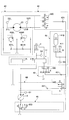
- FIG. 3 shows a configuration example of a main part of a hydraulic circuit mounted on the hydraulic excavator shown in FIG.
- the hydraulic circuit shown in FIG. 3 mainly includes a turning control unit 40, an accumulator unit 41, a first pressure accumulating unit 42, a second pressure accumulating unit 43, a first pressure releasing unit 44, and a second pressure releasing unit 45.
- the turning control unit 40 mainly includes a turning hydraulic motor 21, relief valves 400L and 400R, and check valves 401L and 401R.
- the relief valve 400L is a valve for preventing the hydraulic oil pressure on the first port 21L side of the swing hydraulic motor 21 from exceeding a predetermined swing relief pressure. Specifically, when the pressure of the hydraulic oil on the first port 21L side reaches a predetermined turning relief pressure, the hydraulic oil on the first port 21L side is discharged to the tank.
- the relief valve 400R is a valve for preventing the hydraulic oil pressure on the second port 21R side of the swing hydraulic motor 21 from exceeding a predetermined swing relief pressure. Specifically, when the pressure of the hydraulic oil on the second port 21R side reaches a predetermined turning relief pressure, the hydraulic oil on the second port 21R side is discharged to the tank.
- the check valve 401L is a valve for preventing the hydraulic oil pressure on the first port 21L side from becoming less than the tank pressure. Specifically, when the pressure of the hydraulic oil on the first port 21L side decreases to the tank pressure, the hydraulic oil in the tank is supplied to the first port 21L side.
- the check valve 401R is a valve for preventing the hydraulic oil pressure on the second port 21R side from becoming less than the tank pressure. Specifically, when the pressure of the hydraulic oil on the second port 21R side decreases to the tank pressure, the hydraulic oil in the tank is supplied to the second port 21R side.
- the accumulator unit 41 is a hydraulic circuit element that accumulates the hydraulic oil in the hydraulic circuit and releases the accumulated hydraulic oil as necessary. Specifically, the accumulator unit 41 accumulates hydraulic oil on the braking side (discharge side) of the turning hydraulic motor 21 during turning deceleration. Moreover, the accumulator part 41 accumulate
- the accumulator unit 41 mainly includes an accumulator 410.
- the accumulator 410 is a device that accumulates the hydraulic oil in the hydraulic circuit and releases the accumulated hydraulic oil as necessary.
- the accumulator 410 is a spring type accumulator that uses the restoring force of a spring.
- the first pressure accumulating unit 42 is a hydraulic circuit element that controls the flow of hydraulic oil between the turning control unit 40 (the turning hydraulic motor 21) and the accumulator unit 41.
- the first pressure accumulator 42 mainly includes a first switching valve 420 and a first check valve 421.
- the first switching valve 420 is a valve that controls the flow of hydraulic oil from the turning control unit 40 to the accumulator unit 41 during the pressure accumulation (regeneration) operation of the accumulator unit 41.
- the first switching valve 420 is a three-port three-position switching valve, and an electromagnetic valve that switches the valve position in accordance with a control signal from the controller 30 is used. Further, a proportional valve using a pilot pressure may be used.
- the first switching valve 420 has a first position, a second position, and a third position as valve positions.
- the numbers in parentheses in the figure represent the valve position numbers. The same applies to other switching valves.
- the first position is a valve position for communicating the first port 21L and the accumulator unit 41.
- the second position is a valve position that blocks communication between the turning control unit 40 and the accumulator unit 41.
- the third position is a valve position for communicating the second port 21R and the accumulator unit 41.
- the first check valve 421 is a valve that prevents hydraulic oil from flowing from the accumulator unit 41 to the turning control unit 40.
- the second pressure accumulating unit 43 is a hydraulic circuit element that controls the flow of hydraulic oil between the control valve 17 and the accumulator unit 41.
- the second pressure accumulating portion 43 is disposed between the boom cylinder flow control valve 17B, the tank, and the accumulator portion 41, and mainly includes a second switching valve 430 and a second check valve 431.
- the boom cylinder flow control valve 17B may be one or more other flow control valves such as an arm cylinder flow control valve.
- the second switching valve 430 is a valve that controls the flow of hydraulic oil from the hydraulic actuator to the accumulator unit 41 during the pressure accumulation (regeneration) operation of the accumulator unit 41.
- the second switching valve 430 is a 3-port 2-position switching valve, and an electromagnetic valve that switches the valve position in accordance with a control signal from the controller 30 is used. Further, a proportional valve using a pilot pressure may be used.
- the second switching valve 430 has a first position and a second position as valve positions.
- the first position is a valve position that connects the discharge port of the boom cylinder flow control valve 17B and the tank, and blocks communication between the discharge port of the boom cylinder flow control valve 17B and the accumulator unit 41.
- the second position is a valve position where the discharge port of the boom cylinder flow control valve 17B and the accumulator unit 41 are communicated and the communication between the discharge port of the boom cylinder flow control valve 17B and the tank is cut off. It is.
- the second check valve 431 is a valve that prevents hydraulic oil from flowing from the accumulator unit 41 to the second switching valve 430.
- the first pressure release part 44 is a hydraulic circuit element that controls the flow of hydraulic oil among the main pump 14, the control valve 17, and the accumulator part 41.
- the first pressure release unit 44 mainly includes a third switching valve 440 and a third check valve 441.
- the third switching valve 440 is a valve that controls the flow of hydraulic oil from the accumulator unit 41 to the junction point on the downstream side of the main pump 14 during the pressure release (powering) operation of the accumulator unit 41.
- the third switching valve 440 is a 2-port 2-position switching valve, and an electromagnetic valve that switches the valve position in accordance with a control signal from the controller 30 is used. Further, a proportional valve using a pilot pressure may be used.
- the third switching valve 440 has a first position and a second position as valve positions. The first position is a valve position that blocks communication between the junction on the downstream side of the main pump 14 and the accumulator unit 41. The second position is a valve position at which the confluence point on the downstream side of the main pump 14 communicates with the accumulator unit 41.
- the third check valve 441 is a valve that prevents hydraulic oil from flowing from the main pump 14 to the accumulator unit 41.
- the second pressure release unit 45 is a hydraulic circuit element that controls the flow of hydraulic oil between the tank, the main pump 14 and the accumulator unit 41.
- the second pressure release part 45 mainly includes a fourth switching valve 450.
- the fourth switching valve 450 is a valve that controls the flow of the hydraulic oil from the accumulator unit 41 to the merging point on the upstream side of the main pump 14 during the pressure release (powering) operation of the accumulator unit 41.
- the fourth switching valve 450 is a three-port two-position switching valve, and an electromagnetic valve that switches the valve position in accordance with a control signal from the controller 30 is used. Further, a proportional valve using a pilot pressure may be used.
- the fourth switching valve 450 has a first position and a second position as valve positions.
- the first position is a valve position that allows the main pump 14 and the tank to communicate with each other and blocks communication between the main pump 14 and the accumulator unit 41.
- the second position is a valve position that blocks communication between the main pump 14 and the tank and allows the main pump 14 and the accumulator unit 41 to communicate with each other.
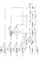
- FIG. 4 is a flowchart showing the flow of the pressure accumulation / release pressure process, and the controller 30 repeatedly executes this pressure accumulation / release pressure process at a predetermined cycle.
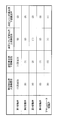
- FIG. 5 is a correspondence table showing the correspondence between the state of the hydraulic circuit in FIG. 3 and the state of each switching valve.
- the controller 30 determines whether or not the hydraulic actuator has been operated based on the outputs of various sensors for detecting the state of the hydraulic excavator (step ST1). In this embodiment, the controller 30 determines whether or not the hydraulic actuator has been operated based on the output of the pressure sensor 29.
- the controller 30 determines whether the operation is a regenerative operation or a power running operation (step ST2). In this embodiment, the controller 30 performs a regenerative operation such as a turning deceleration operation or a boom lowering operation based on the output of the pressure sensor 29, or a power running operation such as a turning acceleration operation or a boom raising operation. It is determined.
- a regenerative operation such as a turning deceleration operation or a boom lowering operation based on the output of the pressure sensor 29, or a power running operation such as a turning acceleration operation or a boom raising operation. It is determined.
- step ST2 If it is determined that the regenerative operation has been performed (YES in step ST2), the controller 30 determines whether the regenerative operation is a turning deceleration operation or another regenerative operation (step ST3).
- the controller 30 determines whether or not the accumulator unit 41 is in a state where pressure accumulation is possible (step ST4).
- the controller 30 includes an accumulator unit based on the braking side (discharge side) pressure Pso of the swing hydraulic motor 21 output from the pressure sensor S2L or the pressure sensor S2R and the accumulator pressure Pa output from the pressure sensor S3. It is determined whether 41 is in a state capable of accumulating pressure.
- the controller 30 determines that the accumulator unit 41 is in a state where pressure can be accumulated when the pressure Pso exceeds the accumulator pressure Pa, and the accumulator unit 41 can accumulate pressure when the pressure Pso is equal to or less than the accumulator pressure Pa. It is determined that there is no state.
- step ST4 the controller 30 will make the state of a hydraulic circuit the state of a "turning pressure accumulation" (step ST5).
- the controller 30 sets the first switching valve 420 to the first position or the third position, and connects the turning control part 40 and the accumulator part 41 through the first pressure accumulation part 42. Communicate. Further, the controller 30 places the second switching valve 430 in the first position, communicates the discharge port of the boom cylinder flow control valve 17B and the tank, and connects the discharge port of the boom cylinder flow control valve 17B to the accumulator unit 41. Block communication with In addition, the controller 30 sets the third switching valve 440 to the first position, and blocks communication between the junction on the downstream side of the main pump 14 and the accumulator unit 41. Further, the controller 30 sets the fourth switching valve 450 to the first position, allows the main pump 14 and the tank to communicate, and blocks communication between the main pump 14 and the accumulator unit 41.
- the hydraulic fluid on the braking side of the swing hydraulic motor 21 flows to the accumulator part 41 through the first pressure accumulation part 42 and is accumulated in the accumulator 410.
- the hydraulic fluid on the brake side of the swing hydraulic motor 21 is located at a place other than the accumulator unit 41. Will not flow into.
- step ST3 determines whether or not the accumulator unit 41 is in a state in which pressure accumulation is possible (step ST3). ST6).
- the controller 30 is in a state in which the accumulator unit 41 can accumulate pressure based on the pressure Pbb of the bottom side oil chamber of the boom cylinder 7 output from the pressure sensor S4 and the accumulator pressure Pa output from the pressure sensor S3. It is determined whether or not there is.
- the controller 30 determines that the accumulator unit 41 is in a state where pressure can be accumulated when the pressure Pbb exceeds the accumulator pressure Pa, and the accumulator unit 41 can accumulate pressure when the pressure Pbb is equal to or less than the accumulator pressure Pa. It is determined that there is no state.
- step ST6 when it determines with the accumulator part 41 being in the state which can be pressure-accumulated (YES of step ST6), the controller 30 makes the state of a hydraulic circuit the state of "hydraulic cylinder pressure accumulation" (step ST7).
- the controller 30 determines that the regenerative operation is a boom lowering operation, the controller 30 changes the state of the hydraulic circuit to the “hydraulic cylinder pressure accumulation” state.
- the controller 30 sets the first switching valve 420 to the second position, and between the turning control unit 40 and the accumulator unit 41 through the first accumulating unit 42. Block communication. Further, the controller 30 places the second switching valve 430 in the second position, communicates the discharge port of the boom cylinder flow control valve 17B and the accumulator portion 41, and connects the discharge port of the boom cylinder flow control valve 17B and the tank. Block communication with In addition, since the state of the 3rd switching valve 440 and the 4th switching valve 450 is the same as the state at the time of "rotation pressure accumulation", description is abbreviate
- step ST2 when it is determined in step ST2 that the operation is not a regenerative operation but a power running operation (NO in step ST2), the controller 30 determines whether or not the pressure accumulation state of the accumulator unit 41 is a state suitable for releasing pressure ( Step ST8). In the present embodiment, the controller 30 determines whether or not the accumulator pressure Pa is less than a predetermined pressure Pa0 based on the output of the pressure sensor S3.
- step ST8 determines with the pressure accumulation state of the accumulator part 41 being a state suitable for pressure release (YES of step ST8), the controller 30 will be less than the discharge pressure Pp which is the output of the pressure sensor S1? It is determined whether or not (step ST9). In this embodiment, when it is determined that the accumulator pressure Pa is equal to or higher than the predetermined pressure Pa0, the controller 30 determines whether or not the accumulator pressure Pa is less than the discharge pressure Pp.
- step ST9 If the controller 30 determines that the accumulator pressure Pa is less than the discharge pressure Pp (YES in step ST9), the controller 30 sets the state of the hydraulic circuit to the “upstream side pressure release” state (step ST10).
- the controller 30 sets the first switching valve 420 to the second position, and between the turning control unit 40 and the accumulator unit 41 through the first pressure accumulating unit 42. Block communication. Further, the controller 30 places the second switching valve 430 in the first position, communicates the discharge port of the boom cylinder flow control valve 17B and the tank, and connects the discharge port of the boom cylinder flow control valve 17B to the accumulator unit 41. Block communication with In addition, the controller 30 sets the third switching valve 440 to the first position, and blocks communication between the junction on the downstream side of the main pump 14 and the accumulator unit 41. Furthermore, the controller 30 sets the fourth switching valve 450 to the second position, blocks communication between the main pump 14 and the tank, and allows the main pump 14 and the accumulator unit 41 to communicate.
- the hydraulic oil in the accumulator part 41 is discharged through the second pressure release part 45 at the junction on the upstream side of the main pump 14. Further, since the first switching valve 420, the second switching valve 430, and the third switching valve 440 are in the cut-off state when viewed from the accumulator unit 41, the hydraulic oil in the accumulator unit 41 is merged on the upstream side of the main pump 14. It will not be released anywhere else.
- step ST9 If it is determined in step ST9 that the accumulator pressure Pa is equal to or higher than the discharge pressure Pp (NO in step ST9), the controller 30 changes the state of the hydraulic circuit to the “downstream pressure release” state (step ST11).
- the controller 30 places the third switching valve 440 in the second position and causes the confluence point on the downstream side of the main pump 14 to communicate with the accumulator unit 41.
- the controller 30 sets the fourth switching valve 450 to the first position, communicates the main pump 14 and the tank, and blocks communication between the main pump 14 and the accumulator unit 41.
- the state of the 1st switching valve 420 and the 2nd switching valve 430 is the same as the state at the time of "upstream side pressure release", description is abbreviate
- the hydraulic oil in the accumulator part 41 is discharged through the first pressure release part 44 at the junction on the downstream side of the main pump 14. Further, since the first switching valve 420, the second switching valve 430, and the fourth switching valve 450 are in the cut-off state when viewed from the accumulator unit 41, the hydraulic oil in the accumulator unit 41 is merged at the downstream side of the main pump 14. It will not be released anywhere else.
- step ST8 If it is determined in step ST8 that the accumulator 41 is not in a state suitable for releasing pressure (NO in step ST8), the controller 30 changes the state of the hydraulic circuit to the “tank supply” state (step ST12). The release of hydraulic oil from the accumulator unit 41 is prohibited.
- the controller 30 sets the third switching valve 440 to the first position, and blocks communication between the confluence on the downstream side of the main pump 14 and the accumulator unit 41. To do. Further, the controller 30 sets the fourth switching valve 450 to the first position, allows the main pump 14 and the tank to communicate with each other, and blocks communication between the main pump 14 and the accumulator unit 41.
- the state of the 1st switching valve 420 and the 2nd switching valve 430 is the same as the state at the time of "upstream side pressure release", description is abbreviate
- the main pump 14 supplies the hydraulic oil sucked from the tank to the hydraulic actuator being operated.
- the 1st switching valve 420, the 2nd switching valve 430, the 3rd switching valve 440, and the 4th switching valve 450 are each the interruption
- step ST1 If it is determined in step ST1 that the hydraulic actuator is not operated (NO in step ST1), the controller 30 sets the state of the hydraulic circuit to the “standby” state (step ST13).
- the state of the first switching valve 420, the second switching valve 430, the third switching valve 440, and the fourth switching valve 450 is the same as that in the “tank supply” state. The same.
- the hydraulic oil in the accumulator unit 41 is not accumulated or released.
- step ST4 when it is determined in step ST4 that the accumulator unit 41 is not in a state where pressure accumulation is possible (NO in step ST4), the controller 30 sets the state of the hydraulic circuit to a “standby” state (step ST13). In this case, since the first switching valve 420 is in the second position, the hydraulic oil on the brake side (discharge side) of the swing hydraulic motor 21 is discharged to the tank via the relief valve 400L or the relief valve 400R.
- step ST6 when it is determined in step ST6 that the accumulator unit 41 is not in a state where pressure accumulation is possible (NO in step ST6), the controller 30 sets the state of the hydraulic circuit to a “standby” state (step ST13). In this case, since the second switching valve 430 is in the first position, the hydraulic oil in the bottom side oil chamber of the boom cylinder 7 is discharged to the tank via the boom cylinder flow control valve 17B and the second switching valve 430.
- FIG. 6 is an example of temporal transitions of the control lever pressure, the accumulator pressure, and the control signals for the third switching valve 440 and the fourth switching valve 450 when the accumulator 410 is released.
- the transition of the operation lever pressure Pi in the upper part of FIG. 6 represents the transition of the pilot pressure that varies according to the operation of the boom operation lever in the boom raising direction.
- the transition of the accumulator pressure Pa in the middle of FIG. 6 represents the transition of the detection value of the pressure sensor S3.
- the transition of the control signal in the lower stage of FIG. 6 shows the transition of the control signal for the third switching valve 440 (solid line) and the transition of the control signal for the fourth switching valve 450 (dotted line).
- the controller 30 determines whether or not the accumulator pressure Pa is equal to or higher than a predetermined pressure Pa0.
- the controller 30 determines that the accumulator pressure Pa is equal to or higher than the predetermined pressure Pa0 and the accumulator pressure Pa is at a level suitable for releasing pressure, the controller 30 releases the hydraulic oil in the accumulator 410.
- the controller 30 starts releasing the hydraulic oil in the accumulator 410 at time t1.
- the controller 30 sets the state of the hydraulic circuit to “downstream side pressure release”. Put it in a state.
- the discharge pressure Pp is actually a fluctuating value that changes according to the load, but in the present embodiment, it is a constant value for the sake of simplicity of explanation.
- the controller 30 sets the level of the control signal for the third switching valve 440 to the ON level (level for realizing the second position) at time t1.
- the third switching valve 440 that has received the control signal of the ON level is in the second position, and connects the confluence point on the downstream side of the main pump 14 and the accumulator 410.
- the bottom side oil chamber of the boom cylinder 7 directly receives the hydraulic oil discharged from the accumulator 410. That is, the bottom side oil chamber of the boom cylinder 7 receives and expands the hydraulic oil discharged from the accumulator 410 without going through the main pump 14 and raises the boom 4.
- the accumulator 410 discharges the hydraulic oil in the accumulator 410 to the junction on the downstream side of the main pump 14 at time t1. Therefore, as shown in the middle part of FIG. 6, the accumulator pressure Pa decreases as time passes, and falls below the discharge pressure Pp at time t2.
- the controller 30 If it is determined at time t2 that the accumulator pressure Pa is less than the discharge pressure Pp, the controller 30 changes the state of the hydraulic circuit to the “upstream side pressure release” state.
- the controller 30 sets the level of the control signal for the third switching valve 440 to the OFF level (level for realizing the first position) at time t2, as shown in the lower part of FIG.
- the level of the control signal for the fourth switching valve 450 is turned ON. Receiving the OFF level control signal, the third switching valve 440 is in the first position, and the communication between the confluence on the downstream side of the main pump 14 and the accumulator 410 is cut off. On the other hand, the 4th switching valve 450 which received the control signal of ON level will be in a 2nd position, and the confluence
- the bottom side oil chamber of the boom cylinder 7 indirectly receives the hydraulic oil discharged from the accumulator 410. That is, the bottom oil chamber of the boom cylinder 7 receives and expands the hydraulic oil discharged from the main pump 14 that has sucked the hydraulic oil discharged from the accumulator 410 and continues to raise the boom 4.
- the accumulator 410 stops releasing the hydraulic oil in the accumulator 410 to the junction on the downstream side of the main pump 14, and the hydraulic oil in the accumulator 410 is on the upstream side of the main pump 14. Release to the junction. Thereafter, as shown in the middle part of FIG. 6, the accumulator pressure Pa continues to decrease as time passes, and falls below the predetermined pressure Pa0 at time t3.
- the controller 30 When it is determined at time t3 that the accumulator pressure Pa is less than the predetermined pressure Pa0, the controller 30 changes the state of the hydraulic circuit to the “tank supply” state.
- the controller 30 sets the level of the control signal for the fourth switching valve 450 to the OFF level at time t3.
- the third switching valve 440 that has received the OFF level control signal is in the first position, and the communication between the confluence on the upstream side of the main pump 14 and the accumulator 410 is cut off. That is, the controller 30 stops releasing any hydraulic oil in the accumulator 410. Then, the bottom side oil chamber of the boom cylinder 7 receives and expands the hydraulic oil discharged from the main pump 14 that has sucked the hydraulic oil from the tank, and continues to raise the boom 4.
- the hydraulic circuit described above can be reused after accumulating hydraulic oil with regenerative energy discharged from the hydraulic actuator in the accumulator 410.
- the hydraulic circuit described above makes it possible to use the hydraulic oil in the accumulator portion 41 not only when the accumulator pressure Pa is higher than or equal to the discharge pressure Pp but also when the accumulator pressure Pa is lower than the discharge pressure Pp. Therefore, the hydraulic circuit described above can use the hydraulic energy accumulated in the accumulator unit 41 more efficiently.
- the hydraulic circuit described above executes the pressure release (powering) operation of the accumulator unit 41 even when the pressure of the accumulator unit 41 is lower than the pressure on the drive side of the hydraulic actuator to be operated. Can be made.
- hydraulic circuit described above does not flow hydraulic oil into the accumulator unit 41 when a power running operation is performed, but hydraulic fluid may flow into the accumulator unit 41.
- the controller 30 alternatively executes the swivel pressure accumulation and the hydraulic cylinder pressure accumulation, but may execute the swirl pressure accumulation and the hydraulic cylinder pressure accumulation simultaneously. Specifically, the controller 30 may set the second switching valve 430 to the second position while setting the first switching valve 420 to the first position or the third position.
- the hydraulic circuit described above can accumulate return oil from the hydraulic actuator in the accumulator unit 41 and release the accumulated hydraulic oil as necessary. Therefore, the hydraulic circuit described above can reduce the capacity of the tank compared to the configuration without the accumulator portion 41, or can omit the tank itself.
- the hydraulic actuator is driven by using the hydraulic oil discharged from the main pump 14 or by using the hydraulic oil discharged from the main pump 14 and the hydraulic oil accumulated in the accumulator unit 41 in combination.
- the hydraulic circuit described above allows the flow of hydraulic oil from the main pump 14 to the accumulator unit 41 by omitting the third check valve 441, and the accumulator unit 41 accumulates the hydraulic oil discharged by the main pump 14. You may be able to do it.
- the hydraulic circuit described above may be configured such that the hydraulic actuator can be driven using only the hydraulic oil accumulated in the accumulator unit 41.
- the hydraulic circuit described above has a configuration in which the hydraulic oil from the accumulator unit 41 is merged at the upstream merging point or the downstream merging point of the main pump 14.
- the present invention is not limited to this configuration.
- the hydraulic circuit described above has a configuration in which the hydraulic fluid can be discharged directly from the accumulator portion 41 to the hydraulic actuator instead of the configuration in which the hydraulic fluid from the accumulator portion 41 is merged at the junction on the downstream side of the main pump 14. You may have.
- the hydraulic circuit described above may have a configuration in which the hydraulic oil from the accumulator unit 41 is merged at the merge point on the upstream side of the main pump 14.
- the hydraulic circuit described above allows the hydraulic oil from the accumulator unit 41 to be discharged at the junction on the upstream side of the main pump 14. Therefore, the main pump 14 can reduce the absorption horsepower (torque required to discharge a predetermined amount of hydraulic oil) compared with the case where the hydraulic oil having a relatively low pressure is sucked from the tank and discharged, thereby saving energy. Can promote. Moreover, the main pump 14 can improve the responsiveness of discharge amount control.
- the accumulator unit 41 has a single accumulator 410.
- the present invention is not limited to this configuration.
- the accumulator unit 41 may include two or more accumulators connected in parallel.
- the capacity of each accumulator is arbitrary and may be the same capacity or different capacity.
- the maximum discharge pressure of each accumulator may be a different pressure. This is because an accumulator as a supply source or accumulation destination of hydraulic oil can be selected from a plurality of accumulators having different maximum discharge pressures according to a required discharge pressure.
- the “maximum discharge pressure” is the maximum pressure that can be discharged by the accumulator, and is the pressure determined by the maximum pressure of the accumulator during the pressure accumulation (regeneration) operation.
- each accumulator may be accumulated or released at different timings, and two or more accumulators may be accumulated or released at partially or entirely overlapping timing.
- FIG. 7 shows a configuration example of a main part of another hydraulic circuit mounted on the hydraulic excavator shown in FIG.
- the accumulator switching valve 411 is a valve that controls communication / blocking between the accumulator 410 and other parts of the hydraulic circuit.
- the accumulator switching valve 411 is a 2-port 2-position switching valve, and an electromagnetic valve that switches the valve position in accordance with a control signal from the controller 30 is used. Further, a proportional valve using a pilot pressure may be used.
- the accumulator switching valve 411 has a first position and a second position as valve positions. The first position is a valve position that blocks communication between the accumulator 410 and other parts of the hydraulic circuit. The second position is a valve position that allows the accumulator 410 to communicate with other parts of the hydraulic circuit.
- the controller 30 can cause the hydraulic oil flowing out from the turning control unit 40 through the first switching valve 420 to join the junction on the upstream side or the downstream side of the main pump 14 without accumulating in the accumulator 410. it can.
- the controller 30 sets one of the third switching valve 440 and the fourth switching valve 450 while setting the accumulator switching valve 411 to the first position and the first switching valve 420 to the first position or the third position. Is the second position. Thereby, the controller 30 can join the hydraulic oil flowing out from the braking side of the swing hydraulic motor 21 to the merging point on the upstream side or the downstream side of the main pump 14.
- the controller 30 joins the hydraulic oil flowing out from the boom cylinder flow control valve 17B through the second switching valve 430 to the merging point on the upstream side or the downstream side of the main pump 14 without accumulating in the accumulator 410. be able to.
- the controller 30 sets either the third switching valve 440 or the fourth switching valve 450 to the second position while setting the accumulator switching valve 411 to the first position and the second switching valve 430 to the second position. And thereby, the controller 30 can join the hydraulic oil flowing out from the bottom side oil chamber of the boom cylinder 7 to the merging point on the upstream side or the downstream side of the main pump 14.
- FIG. 8 is a flowchart showing the flow of pressure accumulation / release processing in the hydraulic circuit of FIG. 7, and FIG. 9 is a correspondence table showing the correspondence between the state of the hydraulic circuit of FIG. 7 and the state of each switching valve. It is. Further, FIG. 8 is different from the flowchart of FIG. 4 in the processing (the processing in the case of NO in step ST4 and the processing in the case of NO in step ST6) when it is determined that the accumulator unit 41 is not in a state where pressure accumulation is possible.
- the other points are common to the flowchart of FIG. Therefore, illustration and description of common parts are omitted.
- step ST3 If it is determined in step ST3 that the regenerative operation is a turning deceleration operation (YES in step ST3), the controller 30 determines whether or not the accumulator unit 41 is in a state where pressure accumulation is possible (step ST4).
- step ST41 the controller 30 determines whether or not the boom 4 is operated based on the output of the pressure sensor 29, that is, whether or not the boom cylinder 7 is driven.
- Step ST41 If it is determined that the hydraulic cylinder is being driven (YES in step ST41), the controller 30 determines whether or not the brake side (discharge side) pressure Pso of the swing hydraulic motor 21 is equal to or higher than the discharge pressure Pp. (Step ST42).
- the controller 30 changes the state of the hydraulic circuit to the “revolution side upstream regeneration” state (step ST43).
- the controller 30 sets the first switching valve 420 to the first position or the third position, sets the fourth switching valve 450 to the second position, and stores the accumulator.
- the switching valve 411 is set to the first position.
- the controller 30 causes the turning control unit 40 and the junction on the upstream side of the main pump 14 to communicate with each other while blocking communication between the accumulator 410 and other parts of the hydraulic circuit.
- the controller 30 makes the 2nd switching valve 430 a 1st position, and connects the discharge port and tank of the boom cylinder flow control valve 17B.
- the controller 30 sets the third switching valve 440 to the first position, and blocks communication between the turning control unit 40 and the junction on the downstream side of the main pump 14.
- step ST42 if it is determined that the pressure Pso is equal to or higher than the discharge pressure Pp (YES in step ST42), the controller 30 changes the state of the hydraulic circuit to the “revolution side downstream regeneration” state (step ST44).
- the controller 30 sets the first switching valve 420 to the first position or the third position, sets the third switching valve 440 to the second position, and stores the accumulator.
- the switching valve 411 is set to the first position.
- the controller 30 allows the turning control unit 40 and the junction on the downstream side of the main pump 14 to communicate with each other while blocking communication between the accumulator 410 and the other part of the hydraulic circuit.
- the controller 30 makes the 2nd switching valve 430 a 1st position, and connects the discharge port and tank of the boom cylinder flow control valve 17B.
- the controller 30 sets the fourth switching valve 450 to the first position, and blocks communication between the turning control unit 40 and the junction on the upstream side of the main pump 14.
- step ST41 If it is determined in step ST41 that the hydraulic cylinder is not driven (NO in step ST41), the controller 30 sets the state of the hydraulic circuit to the “standby” state (step ST13). In this case, since the first switching valve 420 is in the second position, the hydraulic oil on the brake side (discharge side) of the swing hydraulic motor 21 is discharged to the tank via the relief valve 400L or the relief valve 400R.
- step ST3 If it is determined in step ST3 that the regenerative operation is a regenerative operation other than the turning deceleration operation (NO in step ST3), the controller 30 determines whether or not the accumulator unit 41 is in a state in which pressure accumulation is possible (step ST3). ST6). In this embodiment, when the controller 30 determines that the regenerative operation is a boom lowering operation, the controller 30 determines whether or not the accumulator unit 41 is in a state where pressure accumulation is possible.
- step ST6 when it determines with the accumulator part 41 not being in the state which can be pressure-accumulated (NO of step ST6), the controller 30 will determine whether turning acceleration operation is performed (step ST61).
- the controller 30 determines whether or not the pressure Pbb of the bottom side oil chamber of the boom cylinder 7 is equal to or higher than the discharge pressure Pp (step). ST62).
- the controller 30 changes the state of the hydraulic circuit to the state of “hydraulic cylinder discharge flow upstream side regeneration” (step ST63).
- the controller 30 sets the second switching valve 430 to the second position, the fourth switching valve 450 to the second position, and the accumulator switching valve 411. Is the first position.
- the controller 30 allows the bottom oil chamber of the boom cylinder 7 and the upstream junction of the main pump 14 to communicate with each other while blocking communication between the accumulator 410 and other parts of the hydraulic circuit.
- the controller 30 sets the first switching valve 420 to the second position and blocks communication between the turning control unit 40 and the first pressure accumulating unit 42.
- the controller 30 sets the third switching valve 440 to the first position, and blocks communication between the bottom side oil chamber of the boom cylinder 7 and the junction on the downstream side of the main pump 14.
- step ST62 the controller 30 changes the state of the hydraulic circuit to the state of “hydraulic cylinder exhaust flow downstream regeneration” (step ST64).
- the controller 30 sets the second switching valve 430 to the second position, the third switching valve 440 to the second position, and the accumulator switching valve 411. Is the first position.
- the controller 30 allows the bottom oil chamber of the boom cylinder 7 and the downstream junction point of the main pump 14 to communicate with each other while blocking communication between the accumulator 410 and other parts of the hydraulic circuit.
- the controller 30 sets the first switching valve 420 to the second position and blocks communication between the turning control unit 40 and the first pressure accumulating unit 42.
- the controller 30 sets the fourth switching valve 450 to the first position, and blocks communication between the bottom oil chamber of the boom cylinder 7 and the upstream junction of the main pump 14.
- step ST61 If it is determined in step ST61 that the turning acceleration operation has not been performed (NO in step ST61), the controller 30 sets the state of the hydraulic circuit to the “standby” state (step ST13). In this case, since the second switching valve 430 is in the first position, the hydraulic oil in the bottom side oil chamber of the boom cylinder 7 is discharged to the tank via the boom cylinder flow control valve 17B and the second switching valve 430.
- the hydraulic circuit of FIG. 7 has the effect that hydraulic oil with regenerative energy discharged from the hydraulic actuator can be reused without accumulating in the accumulator 410. Play.
- the accumulator 410 accumulates hydraulic oil from the swing hydraulic motor 21 and the boom cylinder 7.
- the present invention is not limited to this configuration.
- the accumulator 410 may be configured to accumulate hydraulic oil from the swing hydraulic motor 21 and other hydraulic actuators.
- the hydraulic actuator is discharged from the regenerated hydraulic actuators.
- the hydraulic oil may be merged at the merging point on the upstream side or downstream side of the main pump 14 and supplied to the hydraulic actuator on which the power running operation has been performed.
- the accumulator 410 may be configured to accumulate only the hydraulic oil from the turning hydraulic motor 21.
- the second pressure accumulating unit 43 may be omitted.
- the accumulator 410 may be configured to accumulate only hydraulic fluid from one or a plurality of hydraulic actuators other than the swing hydraulic motor 21.
- the first pressure accumulator 42 may be omitted, and the swing hydraulic motor 21 may be an electric motor.
- FIG. 10 is a block diagram showing another configuration of the drive system of the hydraulic excavator shown in FIG.
- the mechanical power system is indicated by a double line
- the high-pressure hydraulic line is indicated by a thick solid line
- the pilot line is indicated by a broken line
- the electric drive / control system is indicated by a thin solid line.
- a main pump 14 as a variable displacement hydraulic pump
- a pilot pump 15 as a fixed displacement hydraulic pump
- a pump motor 35 as a variable displacement hydraulic pump motor. It is connected.
- a control valve 17 is connected to the main pump 14 via a high pressure hydraulic line 16.
- An operation device 26 is connected to the pilot pump 15 via a pilot line 25.
- the control valve 17 is a device that controls the hydraulic system in the hydraulic excavator.
- the hydraulic actuators such as the traveling hydraulic motor 1A (for right), the traveling hydraulic motor 1B (for left), the boom cylinder 7, the arm cylinder 8, the bucket cylinder 9 and the swing hydraulic motor 21 are connected to the control valve 17 via a high pressure hydraulic line. It is connected to the.
- the operating device 26 includes a lever 26A, a lever 26B, and a pedal 26C.
- the lever 26A, the lever 26B, and the pedal 26C are connected to the control valve 17 and the pressure sensor 29 via hydraulic lines 27 and 28, respectively.
- the pressure sensor 29 is a sensor for detecting the operation content of the operator using the operation device 26.
- the pressure sensor 29 detects the operation direction and the operation amount of the lever or pedal of the operation device 26 corresponding to each of the hydraulic actuators in the form of pressure, and outputs the detected value to the controller 30.
- the operation content of the operation device 26 may be detected using a sensor other than the pressure sensor.
- the controller 30 is a controller as a main control unit that performs drive control of the hydraulic excavator.
- the controller 30 includes a CPU (Central Processing Unit) and an arithmetic processing unit including an internal memory.
- the controller 30 controls the hydraulic excavator by causing the CPU to execute a drive control program stored in the internal memory.
- the pressure sensor S1 is a sensor that detects the discharge pressure of the main pump 14, and outputs the detected value to the controller 30.
- the pressure sensor S2L is a sensor that detects the pressure of the hydraulic oil on the first port side of the swing hydraulic motor 21, and outputs the detected value to the controller 30.
- the pressure sensor S ⁇ b> 2 ⁇ / b> R is a sensor that detects the pressure of hydraulic oil on the second port side of the swing hydraulic motor 21, and outputs the detected value to the controller 30.
- the pressure sensor S3 is a sensor that detects the pressure of the hydraulic oil in the accumulator unit 41 (hereinafter referred to as “accumulator pressure”), and outputs the detected value to the controller 30.
- the pressure sensor S4 is a sensor that detects the pressure of the hydraulic oil in the bottom side oil chamber of the boom cylinder 7, and outputs the detected value to the controller 30.
- the accumulator unit 41 is a hydraulic circuit element that accumulates the hydraulic oil in the hydraulic circuit and releases the accumulated hydraulic oil as necessary.
- the first pressure accumulating unit 42 is a hydraulic circuit element that controls the flow of hydraulic oil between the swing hydraulic motor 21 and the accumulator unit 41.
- the second pressure accumulating unit 43 is a hydraulic circuit element that controls the flow of hydraulic oil between the control valve 17 and the accumulator unit 41.
- the first pressure release part 44A is a hydraulic circuit element that controls the flow of hydraulic oil among the main pump 14, the control valve 17, and the accumulator part 41.
- the second pressure release unit 45A is a hydraulic circuit element that controls the flow of hydraulic oil between the main pump 14, the tank, and the accumulator unit 41.
- the accumulator unit 41, the first pressure accumulating unit 42, the second pressure accumulating unit 43, the first pressure releasing unit 44A, and the second pressure releasing unit 45A will be described in detail later.
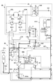
- FIG. 11 shows a configuration example of a main part of a hydraulic circuit mounted on the hydraulic excavator shown in FIG.
- the hydraulic circuit shown in FIG. 11 mainly includes a turning control unit 40, an accumulator unit 41, a first pressure accumulating unit 42, a second pressure accumulating unit 43, a first pressure releasing unit 44A, and a second pressure releasing unit 45A.
- the turning control unit 40 mainly includes a turning hydraulic motor 21, relief valves 400L and 400R, and check valves 401L and 401R.
- the relief valve 400L is a valve for preventing the hydraulic oil pressure on the first port 21L side of the swing hydraulic motor 21 from exceeding a predetermined swing relief pressure. Specifically, when the pressure of the hydraulic oil on the first port 21L side reaches a predetermined turning relief pressure, the hydraulic oil on the first port 21L side is discharged to the tank.
- the relief valve 400R is a valve for preventing the hydraulic oil pressure on the second port 21R side of the swing hydraulic motor 21 from exceeding a predetermined swing relief pressure. Specifically, when the pressure of the hydraulic oil on the second port 21R side reaches a predetermined turning relief pressure, the hydraulic oil on the second port 21R side is discharged to the tank.
- the check valve 401L is a valve for preventing the hydraulic oil pressure on the first port 21L side from becoming less than the tank pressure. Specifically, when the pressure of the hydraulic oil on the first port 21L side decreases to the tank pressure, the hydraulic oil in the tank is supplied to the first port 21L side.
- the check valve 401R is a valve for preventing the hydraulic oil pressure on the second port 21R side from becoming less than the tank pressure. Specifically, when the pressure of the hydraulic oil on the second port 21R side decreases to the tank pressure, the hydraulic oil in the tank is supplied to the second port 21R side.
- the accumulator unit 41 is a hydraulic circuit element that accumulates the hydraulic oil in the hydraulic circuit and releases the accumulated hydraulic oil as necessary. Specifically, the accumulator unit 41 accumulates hydraulic oil on the braking side (discharge side) of the turning hydraulic motor 21 during turning deceleration. Moreover, the accumulator part 41 accumulate
- the accumulator unit 41 mainly includes an accumulator 410 and an accumulator switching valve 411.
- the accumulator 410 is a device that accumulates the hydraulic oil in the hydraulic circuit and releases the accumulated hydraulic oil as necessary.
- the accumulator 410 is a spring type accumulator that uses the restoring force of a spring.
- the accumulator switching valve 411 is a valve that controls the flow of hydraulic oil between the accumulator 410 and the other part of the hydraulic circuit.
- the accumulator switching valve 411 is a 2-port 2-position switching valve, and an electromagnetic valve that switches the valve position in accordance with a control signal from the controller 30 is used. Further, a proportional valve using a pilot pressure may be used.
- the accumulator switching valve 411 has a first position and a second position as valve positions. The numbers in parentheses in the figure represent the valve position numbers. The same applies to other switching valves.
- the first position is a valve position that blocks communication between the accumulator 410 and other parts of the hydraulic circuit.
- the second position is a valve position that allows the accumulator 410 to communicate with other parts of the hydraulic circuit. Note that the accumulator switching valve 411 may be omitted.
- the first pressure accumulating unit 42 is a hydraulic circuit element that controls the flow of hydraulic oil between the turning control unit 40 (the turning hydraulic motor 21) and the accumulator unit 41.
- the first pressure accumulator 42 mainly includes a first switching valve 420 and a first check valve 421.
- the first switching valve 420 is a valve that controls the flow of hydraulic oil from the turning control unit 40 to the accumulator unit 41 during the pressure accumulation (regeneration) operation of the accumulator unit 41.
- the first switching valve 420 is a three-port three-position switching valve, and an electromagnetic valve that switches the valve position in accordance with a control signal from the controller 30 is used. Further, a proportional valve using a pilot pressure may be used.
- the first switching valve 420 has a first position, a second position, and a third position as valve positions.
- the first position is a valve position for communicating the first port 21L and the accumulator unit 41.
- the second position is a valve position that blocks communication between the turning control unit 40 and the accumulator unit 41.
- the third position is a valve position for communicating the second port 21R and the accumulator unit 41.
- the first check valve 421 is a valve that prevents hydraulic oil from flowing from the accumulator unit 41 to the turning control unit 40.
- the second pressure accumulating unit 43 is a hydraulic circuit element that controls the flow of hydraulic oil between the control valve 17 and the accumulator unit 41.
- the second pressure accumulating portion 43 is disposed between the boom cylinder flow control valve 17B, the tank, and the accumulator portion 41, and mainly includes a second switching valve 430 and a second check valve 431.
- the boom cylinder flow control valve 17B may be one or more other flow control valves such as an arm cylinder flow control valve.
- the second switching valve 430 is a valve that controls the flow of hydraulic oil from the hydraulic actuator to the accumulator unit 41 during the pressure accumulation (regeneration) operation of the accumulator unit 41.
- the second switching valve 430 is a 3-port 2-position switching valve, and an electromagnetic valve that switches the valve position in accordance with a control signal from the controller 30 is used. Further, a proportional valve using a pilot pressure may be used.
- the second switching valve 430 has a first position and a second position as valve positions.
- the first position is a valve position that connects the discharge port of the boom cylinder flow control valve 17B and the tank, and blocks communication between the discharge port of the boom cylinder flow control valve 17B and the accumulator unit 41.
- the second position is a valve position where the discharge port of the boom cylinder flow control valve 17B and the accumulator unit 41 are communicated and the communication between the discharge port of the boom cylinder flow control valve 17B and the tank is cut off. It is.
- the second check valve 431 is a valve that prevents hydraulic oil from flowing from the accumulator unit 41 to the second switching valve 430.
- the first pressure release part 44A is a hydraulic circuit element that controls the flow of hydraulic oil among the main pump 14, the control valve 17, and the accumulator part 41.
- the first pressure release portion 44A mainly includes a pump motor 35, a third switching valve 440A, and a third check valve 441A.
- the pump motor 35 is a variable displacement hydraulic pump motor whose discharge flow rate changes according to a control signal from the controller 30, and the minimum flow rate is extremely small, and preferably can be set to substantially zero.
- the pump motor 35 has a rotation shaft coupled to the drive shaft of the engine 11.
- the pump motor 35 is connected to the main pump 14 so that rotation can be transmitted to the main pump 14 via the drive shaft of the engine 11.
- the rotation shaft of the pump motor 35 is coupled to the rotation shaft of the main pump 14 via the drive shaft of the engine 11.
- the rotation shaft of the pump motor 35 may be coupled to the drive shaft of the engine 11 via a clutch mechanism, a continuously variable transmission mechanism (for example, an infinite gear ratio transmission), or the like. In this case, the minimum flow rate may not be set to substantially zero.
- a makeup circuit for preventing cavitation when the pump motor 35 is stopped is installed on the upstream side of the pump motor 35.
- the rotation shaft of the pump motor 35 may be directly coupled to the rotation shaft of the main pump 14 without passing through the drive shaft of the engine 11, and a clutch mechanism, a continuously variable transmission mechanism (for example, an infinite gear ratio) Or the like.
- the pump motor 35 can operate as a hydraulic pump or a hydraulic motor as required.
- the pump motor 35 operates as a hydraulic motor when the accumulator pressure Pa is equal to or higher than the discharge pressure Pp of the main pump 14, and operates as a hydraulic pump when the accumulator pressure Pa is lower than the discharge pressure Pp.
- the pump motor 35 operating as a hydraulic motor assists the rotation of the engine 11 using the hydraulic oil in the accumulator unit 41 at a pressure level equal to or higher than the discharge pressure Pp.
- the pump motor 35 discharges hydraulic oil at a pressure level lower than the discharge pressure Pp, and joins the hydraulic oil at a merging point on the upstream side of the main pump 14. Even when the pump motor 35 operates as a hydraulic motor, the pump motor 35 discharges hydraulic oil at a pressure level equal to or higher than the discharge pressure Pp, and merges the hydraulic oil at a merging point on the downstream side of the main pump 14. Also good.
- the pump motor 35 operating as a hydraulic pump draws in the hydraulic oil in the accumulator unit 41 at a pressure level lower than the discharge pressure Pp using the driving force of the engine 11.
- the pump motor 35 discharges hydraulic oil at a pressure level equal to or higher than the discharge pressure Pp, and merges the hydraulic oil at a junction point on the downstream side of the main pump 14.
- the pump motor 35 discharges hydraulic oil at a pressure level lower than the discharge pressure Pp, and merges the hydraulic oil at a merging point on the upstream side of the main pump 14. Also good.
- the third switching valve 440A is a valve that controls the flow of hydraulic oil from the pump motor 35 to the upstream junction or downstream junction of the main pump 14 during the pressure release (powering) operation of the accumulator unit 41. It is.
- the third switching valve 440A is a 3-port 2-position switching valve, and an electromagnetic valve that switches the valve position in accordance with a control signal from the controller 30 is used. Further, a proportional valve using a pilot pressure may be used.
- the third switching valve 440A has a first position and a second position as valve positions.
- the first position allows communication between the merging point on the upstream side of the main pump 14 and the discharge port of the pump motor 35, and communication between the merging point on the downstream side of the main pump 14 and the discharge port of the pump motor 35. This is the valve position to shut off.
- the second position connects the junction point on the downstream side of the main pump 14 and the discharge port of the pump motor 35, and is between the junction point on the upstream side of the main pump 14 and the discharge port of the pump motor 35. This is the valve position that cuts off the communication.
- the third check valve 441A is a valve that prevents hydraulic oil from flowing from the upstream side of the main pump 14 to the discharge port of the pump motor 35.
- the second pressure release part 45A is a hydraulic circuit element that controls the flow of hydraulic oil between the tank, the main pump 14, and the accumulator part 41.
- the second pressure release part 45A mainly includes a fourth switching valve 450A and a fourth check valve 451A.
- the fourth switching valve 450 ⁇ / b> A is a valve that controls the flow of hydraulic oil from the accumulator unit 41 to the merging point on the upstream side of the main pump 14 during the pressure release (powering) operation of the accumulator unit 41.
- the fourth switching valve 450A is a 2-port 2-position switching valve, and an electromagnetic valve that switches the valve position in accordance with a control signal from the controller 30 is used. Further, a proportional valve using a pilot pressure may be used.
- the fourth switching valve 450A has a first position and a second position as valve positions.
- the first position is a valve position that blocks communication between the confluence on the upstream side of the main pump 14 and the accumulator unit 41.
- the second position is a valve position at which the confluence point on the upstream side of the main pump 14 communicates with the accumulator unit 41.
- the fourth check valve 451A is a valve that prevents hydraulic oil from flowing from the merging point on the upstream side of the main pump 14 and the accumulator unit 41 to the tank.
- FIG. 12 is a flowchart showing the flow of pressure accumulation / release pressure processing, and the controller 30 repeatedly executes this pressure accumulation / release pressure processing at a predetermined cycle.
- FIG. 13 is a correspondence table showing the correspondence between the state of the hydraulic circuit in FIG. 11 and the state of each switching valve.
- FIG. 14 shows the state of the hydraulic circuit at “pump release pressure”
- FIG. 15 shows the state of the hydraulic circuit at “motor release pressure”.
- the controller 30 determines whether or not the hydraulic actuator has been operated based on the outputs of various sensors for detecting the state of the hydraulic excavator (step ST1). In this embodiment, the controller 30 determines whether or not the hydraulic actuator has been operated based on the output of the pressure sensor 29.
- the controller 30 determines whether the operation is a regenerative operation or a power running operation (step ST2). In this embodiment, the controller 30 performs a regenerative operation such as a turning deceleration operation or a boom lowering operation based on the output of the pressure sensor 29, or a power running operation such as a turning acceleration operation or a boom raising operation. It is determined.
- a regenerative operation such as a turning deceleration operation or a boom lowering operation based on the output of the pressure sensor 29, or a power running operation such as a turning acceleration operation or a boom raising operation. It is determined.
- step ST2 If it is determined that the regenerative operation has been performed (YES in step ST2), the controller 30 determines whether the regenerative operation is a turning deceleration operation or another regenerative operation (step ST3).
- the controller 30 includes an accumulator unit based on the braking side (discharge side) pressure Pso of the swing hydraulic motor 21 output from the pressure sensor S2L or the pressure sensor S2R and the accumulator pressure Pa output from the pressure sensor S3. It is determined whether 41 is in a state capable of accumulating pressure.
- the controller 30 determines that the accumulator unit 41 is in a state where pressure can be accumulated when the pressure Pso exceeds the accumulator pressure Pa, and the accumulator unit 41 can accumulate pressure when the pressure Pso is equal to or less than the accumulator pressure Pa. It is determined that there is no state.
- step ST4 the controller 30 will make the state of a hydraulic circuit the state of a "turning pressure accumulation" (step ST5).
- the controller 30 causes the accumulator switching valve 411 to be in the second position, and allows the accumulator 410 to communicate with other parts of the hydraulic circuit. Further, the controller 30 sets the first switching valve 420 to the first position or the third position, and causes the turning control unit 40 and the accumulator unit 41 to communicate with each other through the first pressure accumulating unit 42. Further, the controller 30 places the second switching valve 430 in the first position, communicates the discharge port of the boom cylinder flow control valve 17B and the tank, and connects the discharge port of the boom cylinder flow control valve 17B to the accumulator unit 41.
- the controller 30 places the third switching valve 440 ⁇ / b> A in the first position, and communicates the junction on the upstream side of the main pump 14 and the discharge port of the pump motor 35.
- the controller 30 sets the fourth switching valve 450 ⁇ / b> A to the first position and blocks communication between the confluence on the upstream side of the main pump 14 and the accumulator unit 41.
- the controller 30 stops the pump motor 35 and blocks communication between the third switching valve 440A and the accumulator unit 41.
- the stop of the pump motor 35 is set to a minimum flow rate (for example, approximately zero), or to release the clutch mechanism or switch to a gear ratio at which the output rotation speed of the continuously variable transmission mechanism is approximately zero. Including doing. That is, the controller 30 prohibits the pump motor 35 from supplying hydraulic oil in the accumulator unit 41 to the upstream side and the downstream side of the main pump 14.
- the hydraulic fluid on the braking side of the swing hydraulic motor 21 flows to the accumulator part 41 through the first pressure accumulation part 42 and is accumulated in the accumulator 410. Further, since the second switching valve 430, the third switching valve 440A, and the fourth switching valve 450A are in the cut-off state when viewed from the accumulator unit 41, the hydraulic fluid on the brake side of the swing hydraulic motor 21 is located in a place other than the accumulator unit 41. Will not flow into.
- step ST3 determines whether or not the accumulator unit 41 is in a state in which pressure accumulation is possible (step ST3). ST6).
- the controller 30 is in a state in which the accumulator unit 41 can accumulate pressure based on the pressure Pbb of the bottom side oil chamber of the boom cylinder 7 output from the pressure sensor S4 and the accumulator pressure Pa output from the pressure sensor S3. It is determined whether or not there is.
- the controller 30 determines that the accumulator unit 41 is in a state where pressure can be accumulated when the pressure Pbb exceeds the accumulator pressure Pa, and the accumulator unit 41 can accumulate pressure when the pressure Pbb is equal to or less than the accumulator pressure Pa. It is determined that there is no state.
- step ST6 when it determines with the accumulator part 41 being in the state which can be pressure-accumulated (YES of step ST6), the controller 30 makes the state of a hydraulic circuit the state of "hydraulic cylinder pressure accumulation" (step ST7).
- the controller 30 determines that the regenerative operation is a boom lowering operation, the controller 30 changes the state of the hydraulic circuit to the “hydraulic cylinder pressure accumulation” state.
- the controller 30 sets the first switching valve 420 to the second position, and between the turning control unit 40 and the accumulator unit 41 through the first accumulating unit 42. Block communication. Further, the controller 30 places the second switching valve 430 in the second position, communicates the discharge port of the boom cylinder flow control valve 17B and the accumulator portion 41, and connects the discharge port of the boom cylinder flow control valve 17B and the tank. Block communication with The state of the accumulator switching valve 411, the third switching valve 440A, the fourth switching valve 450A, and the pump motor 35 is the same as the state at the time of “turning pressure accumulation”, and thus the description thereof is omitted.
- step ST2 when it is determined in step ST2 that the operation is not a regenerative operation but a power running operation (NO in step ST2), the controller 30 determines whether or not the pressure accumulation state of the accumulator unit 41 is a state suitable for releasing pressure ( Step ST8). In the present embodiment, the controller 30 determines whether or not the accumulator pressure Pa is less than a predetermined pressure Pa0 based on the output of the pressure sensor S3.
- step ST8 determines with the pressure accumulation state of the accumulator part 41 being a state suitable for pressure release (YES of step ST8), the controller 30 will be less than the discharge pressure Pp which is the output of the pressure sensor S1? It is determined whether or not (step ST9). In this embodiment, when it is determined that the accumulator pressure Pa is equal to or higher than the predetermined pressure Pa0, the controller 30 determines whether or not the accumulator pressure Pa is less than the discharge pressure Pp.
- step ST9 If the controller 30 determines that the accumulator pressure Pa is less than the discharge pressure Pp (YES in step ST9), the controller 30 sets the state of the hydraulic circuit to the “pump release pressure” (step ST10).
- the controller 30 sets the first switching valve 420 to the second position, and between the turning control unit 40 and the accumulator unit 41 through the first pressure accumulating unit 42. Block communication. Further, the controller 30 places the second switching valve 430 in the first position, communicates the discharge port of the boom cylinder flow control valve 17B and the tank, and connects the discharge port of the boom cylinder flow control valve 17B to the accumulator unit 41. Block communication with In addition, the controller 30 places the third switching valve 440 ⁇ / b> A in the second position, and connects the junction on the downstream side of the main pump 14 and the discharge port of the pump motor 35.
- controller 30 sets the fourth switching valve 450 ⁇ / b> A to the second position, and communicates the junction on the upstream side of the main pump 14 and the accumulator unit 41. Moreover, the controller 30 operates the pump motor 35 as a hydraulic pump.
- step ST9 If it is determined in step ST9 that the accumulator pressure Pa is equal to or higher than the discharge pressure Pp (NO in step ST9), the controller 30 sets the state of the hydraulic circuit to the “motor pressure release” state (step ST11).
- the controller 30 places the third switching valve 440 ⁇ / b> A in the first position, and communicates the junction on the upstream side of the main pump 14 and the discharge port of the pump motor 35.
- the controller 30 sets the fourth switching valve 450 ⁇ / b> A to the first position and blocks communication between the confluence on the upstream side of the main pump 14 and the accumulator unit 41.
- the controller 30 operates the pump motor 35 as a hydraulic motor.
- the state of the accumulator switching valve 411, the 1st switching valve 420, and the 2nd switching valve 430 is the same as the state at the time of "pump pressure release", description is abbreviate
- the hydraulic oil in the accumulator unit 41 is lowered to a pressure lower than the discharge pressure Pp by the pump motor 35 and passes through the third switching valve 440A. It is discharged at a confluence on the upstream side of the main pump 14. Further, since the first switching valve 420, the second switching valve 430, and the fourth switching valve 450 ⁇ / b> A are in the cut-off state when viewed from the accumulator unit 41, the hydraulic oil in the accumulator unit 41 is merged on the upstream side of the main pump 14. It will not be released anywhere else.
- the pump motor 35 operates as a hydraulic motor and assists the engine 11. Therefore, the engine 11 can tolerate a larger absorption horsepower in the main pump 14, and the main pump 14 can increase the maximum flow rate that can be discharged.
- ⁇ , Te, Tm, N, and Pp represent efficiency, engine torque, pump motor torque, main pump rotation speed, and discharge pressure, respectively.
- step ST8 If it is determined in step ST8 that the accumulator 41 is not in a state suitable for releasing pressure (NO in step ST8), the controller 30 changes the state of the hydraulic circuit to the “tank supply” state (step ST12). The release of hydraulic oil from the accumulator unit 41 is prohibited.
- the controller 30 sets the accumulator switching valve 411 to the first position, and blocks communication between the accumulator 410 and the other part of the hydraulic circuit.
- the controller 30 places the third switching valve 440 ⁇ / b> A in the first position, and communicates the junction on the upstream side of the main pump 14 and the discharge port of the pump motor 35.
- the controller 30 sets the fourth switching valve 450 ⁇ / b> A to the first position and blocks communication between the confluence on the upstream side of the main pump 14 and the accumulator unit 41.
- the controller 30 stops the pump motor 35 and blocks communication between the third switching valve 440A and the accumulator unit 41.
- since the state of the 1st switching valve 420 and the 2nd switching valve 430 is the same as the state at the time of "pump discharge pressure", description is abbreviate
- the main pump 14 supplies the hydraulic oil sucked from the tank to the hydraulic actuator being operated.
- the first switching valve 420, the second switching valve 430, the third switching valve 440A, and the fourth switching valve 450A are in the cut-off state when viewed from the accumulator unit 41, the hydraulic oil in the accumulator unit 41 is accumulated or discharged. It will never be done. However, the 1st switching valve 420 and the 2nd switching valve 430 may be switched so that the accumulator part 41 can accumulate
- step ST1 If it is determined in step ST1 that the hydraulic actuator is not operated (NO in step ST1), the controller 30 sets the state of the hydraulic circuit to the “standby” state (step ST13).
- step ST4 when it is determined in step ST4 that the accumulator unit 41 is not in a state where pressure accumulation is possible (NO in step ST4), the controller 30 sets the state of the hydraulic circuit to a “standby” state (step ST13). In this case, since the first switching valve 420 is in the second position, the hydraulic oil on the brake side (discharge side) of the swing hydraulic motor 21 is discharged to the tank via the relief valve 400L or the relief valve 400R.
- step ST6 when it is determined in step ST6 that the accumulator unit 41 is not in a state where pressure accumulation is possible (NO in step ST6), the controller 30 sets the state of the hydraulic circuit to a “standby” state (step ST13). In this case, since the second switching valve 430 is in the first position, the hydraulic oil in the bottom side oil chamber of the boom cylinder 7 is discharged to the tank via the boom cylinder flow control valve 17B and the second switching valve 430.
- FIG. 16 shows an example of the temporal transition of the control lever pressure, the accumulator pressure, and the control signal for the accumulator switching valve 411, the third switching valve 440A, and the fourth switching valve 450A when the accumulator 410 is released.
- the transition of the operation lever pressure Pi in the upper part of FIG. 16 represents the transition of the pilot pressure that varies according to the operation of the boom operation lever in the boom raising direction.
- the transition of the accumulator pressure Pa in the middle of FIG. 16 represents the transition of the detection value of the pressure sensor S3.
- 16 is the transition of the control signal for the accumulator switching valve 411 (one-dot chain line), the transition of the control signal for the third switching valve 440A (solid line), and the control signal for the fourth switching valve 450A.
- the transition (dotted line) is shown.
- the controller 30 determines whether or not the accumulator pressure Pa is equal to or higher than a predetermined pressure Pa0.
- the controller 30 determines that the accumulator pressure Pa is equal to or higher than the predetermined pressure Pa0 and the accumulator pressure Pa is at a level suitable for releasing pressure, the controller 30 releases the hydraulic oil in the accumulator 410.
- the controller 30 starts releasing the hydraulic oil in the accumulator 410 at time t1.
- the controller 30 when determining that the accumulator pressure Pa is equal to or higher than the discharge pressure Pp of the main pump 14 at time t1, the controller 30 sets the state of the hydraulic circuit to the “motor pressure release” state.
- the discharge pressure Pp is actually a fluctuating value that changes according to the load, but in the present embodiment, it is a constant value for the sake of simplicity of explanation.
- the controller 30 sets the level of the control signal for the accumulator switching valve 411 to the ON level (level for realizing the second position) at time t1.
- the accumulator switching valve 411 that has received the control signal of the ON level is in the second position, and makes the accumulator 410 communicate with the other part of the hydraulic circuit.
- the controller 30 operates the pump motor 35 as a hydraulic motor. Therefore, the hydraulic oil in the accumulator unit 41 is lowered to a pressure lower than the discharge pressure Pp by the pump motor 35 and is discharged at the confluence on the upstream side of the main pump 14 through the third switching valve 440A in the first position.
- the bottom side oil chamber of the boom cylinder 7 receives and expands the hydraulic oil discharged from the accumulator 410 and raises the boom 4.
- the accumulator 410 discharges the hydraulic oil in the accumulator 410 to the upstream junction of the main pump 14 at time t1. Therefore, as shown in the middle part of FIG. 16, the accumulator pressure Pa decreases with the passage of time and falls below the discharge pressure Pp at time t2.
- the controller 30 If it is determined at time t2 that the accumulator pressure Pa is less than the discharge pressure Pp, the controller 30 changes the state of the hydraulic circuit to the “pump release pressure” state.
- the controller 30 sets the level of the control signal for the third switching valve 440A to the ON level (level for realizing the second position) at time t2, and The level of the control signal for the fourth switching valve 450A is turned ON.
- the third switching valve 440A that has received the control signal of the ON level is in the second position, and connects the junction on the downstream side of the main pump 14 and the discharge port of the pump motor 35.
- the fourth switching valve 450A that has received the control signal of the ON level is in the second position, and the merging point on the upstream side of the main pump 14 and the accumulator 410 are communicated. Then, the controller 30 operates the pump motor 35 as a hydraulic pump.
- a part of the hydraulic oil in the accumulator 41 is increased by the pump motor 35 to a pressure higher than the discharge pressure Pp, and is discharged at the junction on the downstream side of the main pump 14 through the third switching valve 440A. Further, another part of the hydraulic oil in the accumulator part 41 is discharged at the junction on the upstream side of the main pump 14 through the second pressure release part 45A, and the main pump 14 raises the pressure to the discharge pressure Pp or higher. .
- the hydraulic oil discharged from the main pump 14 merges with the hydraulic oil from the third switching valve 440A and flows toward the control valve 17. In this way, the bottom side oil chamber of the boom cylinder 7 receives the hydraulic oil discharged from the accumulator 410 and expands so that the boom 4 continues to rise.
- the accumulator 410 discharges a part of the hydraulic oil in the accumulator 410 to the merging point on the upstream side of the main pump 14 at the time t2, and another part of the hydraulic oil in the accumulator 410. It also discharges to a confluence on the downstream side of the main pump 14. Thereafter, as shown in the middle part of FIG. 16, the accumulator pressure Pa continues to decrease with time, and falls below the predetermined pressure Pa0 at time t3.
- the controller 30 When it is determined at time t3 that the accumulator pressure Pa is less than the predetermined pressure Pa0, the controller 30 changes the state of the hydraulic circuit to the “tank supply” state.
- the controller 30 sets the level of the control signal for each of the accumulator switching valve 411 and the fourth switching valve 450A to the OFF level at time t3.
- the accumulator switching valve 411 and the fourth switching valve 450A that have received the OFF level control signal are each in the first position, the communication between the accumulator 410 and the other part of the hydraulic circuit, and the confluence on the upstream side of the main pump 14 The communication with the accumulator 410 is cut off.
- the controller 30 stops the pump motor 35 and blocks communication between the junction on the downstream side of the main pump 14 and the accumulator 410. That is, the controller 30 stops releasing any hydraulic oil in the accumulator 410.
- the bottom side oil chamber of the boom cylinder 7 receives and expands the hydraulic oil discharged from the main pump 14 that has sucked the hydraulic oil from the tank, and continues to raise the boom 4.
- the hydraulic circuit described above can be reused after accumulating hydraulic oil with regenerative energy discharged from the hydraulic actuator in the accumulator 410.
- the hydraulic circuit described above makes it possible to use the hydraulic oil in the accumulator portion 41 not only when the accumulator pressure Pa is higher than or equal to the discharge pressure Pp but also when the accumulator pressure Pa is lower than the discharge pressure Pp. Therefore, the hydraulic circuit described above can use the hydraulic energy accumulated in the accumulator unit 41 more efficiently.
- the hydraulic circuit described above executes the pressure release (powering) operation of the accumulator unit 41 even when the pressure of the accumulator unit 41 is lower than the pressure on the drive side of the hydraulic actuator to be operated. Can be made.
- hydraulic circuit described above does not flow hydraulic oil into the accumulator unit 41 when a power running operation is performed, but hydraulic fluid may flow into the accumulator unit 41.
- the controller 30 alternatively executes the swivel pressure accumulation and the hydraulic cylinder pressure accumulation, but may execute the swirl pressure accumulation and the hydraulic cylinder pressure accumulation simultaneously. Specifically, the controller 30 may set the second switching valve 430 to the second position while setting the first switching valve 420 to the first position or the third position.
- the hydraulic circuit described above can accumulate return oil from the hydraulic actuator in the accumulator unit 41 and release the accumulated hydraulic oil as necessary. Therefore, the hydraulic circuit described above can reduce the capacity of the tank compared to the configuration without the accumulator portion 41, or can omit the tank itself.
- the hydraulic circuit described above has a configuration in which the hydraulic oil from the accumulator unit 41 is merged at the upstream merging point or the downstream merging point of the main pump 14.
- the present invention is not limited to this configuration.
- the hydraulic circuit described above has a configuration in which the hydraulic fluid can be discharged directly from the accumulator portion 41 to the hydraulic actuator instead of the configuration in which the hydraulic fluid from the accumulator portion 41 is merged at the junction on the downstream side of the main pump 14. You may have.
- the hydraulic circuit described above may have a configuration in which the hydraulic oil from the accumulator unit 41 is merged at the merge point on the upstream side of the main pump 14.
- the hydraulic circuit described above allows the hydraulic oil from the accumulator unit 41 to be discharged at the junction on the upstream side of the main pump 14. Therefore, the main pump 14 can reduce the absorption horsepower (torque required to discharge a predetermined amount of hydraulic oil) compared with the case where the hydraulic oil having a relatively low pressure is sucked from the tank and discharged, thereby saving energy. Can promote. Moreover, the main pump 14 can improve the responsiveness of discharge amount control.
- the accumulator unit 41 has a single accumulator 410.
- the present invention is not limited to this configuration.
- the accumulator unit 41 may include two or more accumulators connected in parallel.
- the capacity of each accumulator is arbitrary and may be the same capacity or different capacity.
- the maximum discharge pressure of each accumulator may be a different pressure. This is because an accumulator as a supply source or accumulation destination of hydraulic oil can be selected from a plurality of accumulators having different maximum discharge pressures according to a required discharge pressure.
- the “maximum discharge pressure” is the maximum pressure that can be discharged by the accumulator, and is the pressure determined by the maximum pressure of the accumulator during the pressure accumulation (regeneration) operation.
- each accumulator may be accumulated or released at different timings, and two or more accumulators may be accumulated or released at partially or entirely overlapping timing.
- FIG. 17 shows a configuration example of a main part of still another hydraulic circuit mounted on the excavator in FIG.
- the hydraulic circuit of FIG. 17 is different from the hydraulic circuit of FIG. 11 in that the fourth switching valve 450A is omitted, but is common to the hydraulic circuit of FIG. 11 in other points.
- the accumulator 410 accumulates hydraulic oil from the swing hydraulic motor 21 and the boom cylinder 7.
- the present invention is not limited to this configuration.
- the accumulator 410 may be configured to accumulate only the hydraulic oil from the turning hydraulic motor 21.
- the second pressure accumulating unit 43 may be omitted.
- the accumulator 410 may be configured to accumulate only hydraulic fluid from one or a plurality of hydraulic actuators other than the swing hydraulic motor 21.
- the first pressure accumulator 42 may be omitted, and the swing hydraulic motor 21 may be an electric motor.
- FIG. 18 is a block diagram showing still another configuration of the drive system of the hydraulic excavator shown in FIG.
- the mechanical power system is indicated by a double line
- the high-pressure hydraulic line is indicated by a thick solid line
- the pilot line is indicated by a broken line
- the electric drive / control system is indicated by a thin solid line.
- a main pump 14 as a variable displacement hydraulic pump and a pilot pump 15 as a fixed displacement hydraulic pump are connected to the output shaft of the engine 11 as a mechanical drive unit.
- a control valve 17 is connected to the main pump 14 via a high-pressure hydraulic line 16 and a first pressure release part 44.
- An operation device 26 is connected to the pilot pump 15 via a pilot line 25.
- the control valve 17 is a device that controls the hydraulic system in the hydraulic excavator.
- the hydraulic actuators such as the traveling hydraulic motor 1A (for right), the traveling hydraulic motor 1B (for left), the boom cylinder 7, the arm cylinder 8, the bucket cylinder 9 and the swing hydraulic motor 21 are connected to the control valve 17 via a high pressure hydraulic line. It is connected to the.
- the operating device 26 includes a lever 26A, a lever 26B, and a pedal 26C.
- the lever 26A, the lever 26B, and the pedal 26C are connected to the control valve 17 and the pressure sensor 29 via hydraulic lines 27 and 28, respectively.
- the pressure sensor 29 is a sensor for detecting the operation content of the operator using the operation device 26.
- the pressure sensor 29 detects the operation direction and the operation amount of the lever or pedal of the operation device 26 corresponding to each of the hydraulic actuators in the form of pressure, and outputs the detected value to the controller 30.
- the operation content of the operation device 26 may be detected using a sensor other than the pressure sensor.
- the controller 30 is a controller as a main control unit that performs drive control of the hydraulic excavator.
- the controller 30 includes a CPU (Central Processing Unit) and an arithmetic processing unit including an internal memory.
- the controller 30 controls the hydraulic excavator by causing the CPU to execute a drive control program stored in the internal memory.
- the pressure sensor S1 is a sensor that detects the discharge pressure of the main pump 14, and outputs the detected value to the controller 30.
- the pressure sensor S2L is a sensor that detects the pressure of the hydraulic oil on the first port side of the swing hydraulic motor 21, and outputs the detected value to the controller 30.
- the pressure sensor S ⁇ b> 2 ⁇ / b> R is a sensor that detects the pressure of hydraulic oil on the second port side of the swing hydraulic motor 21, and outputs the detected value to the controller 30.
- the pressure sensor S3L is a sensor that detects the pressure of the hydraulic oil in the low pressure accumulator unit 41L (hereinafter referred to as “low pressure accumulator pressure”), and outputs the detected value to the controller 30.
- the pressure sensor S3H is a sensor that detects the pressure of the hydraulic oil in the high-pressure accumulator unit 41H (hereinafter referred to as “high-pressure accumulator pressure”), and outputs the detected value to the controller 30.
- the pressure sensor S4 is a sensor that detects the pressure of the hydraulic oil in the bottom side oil chamber of the boom cylinder 7, and outputs the detected value to the controller 30.
- the low pressure accumulator unit 41L is a hydraulic circuit element that accumulates hydraulic oil in the hydraulic circuit and discharges the accumulated hydraulic oil toward the main pump 14.
- the low-pressure accumulator unit 41L serves as a tank that stores hydraulic oil. Therefore, in this embodiment, the tank is omitted. However, a tank may be additionally provided.
- the high-pressure accumulator unit 41H is a hydraulic circuit element that accumulates the hydraulic oil in the hydraulic circuit and releases the accumulated hydraulic oil as necessary.
- the high-pressure accumulator part 41H has a maximum discharge pressure that is higher than the maximum discharge pressure of the low-pressure accumulator part 41L.
- the “maximum discharge pressure” is the maximum pressure that can be discharged by the accumulator, and is a pressure determined by the maximum pressure of the accumulator during the pressure accumulation (regeneration) operation.
- the first pressure accumulating unit 42 is a hydraulic circuit element that controls the flow of hydraulic oil between the swing hydraulic motor 21 and the high pressure accumulator unit 41H.
- the second pressure accumulating unit 43 is a hydraulic circuit element that controls the flow of hydraulic oil among the control valve 17, the low pressure accumulator unit 41L, and the high pressure accumulator unit 41H.
- the first pressure release part 44 is a hydraulic circuit element that controls the flow of hydraulic oil among the main pump 14, the control valve 17, and the high-pressure accumulator part 41H.
- the second pressure release part 45 is a hydraulic circuit element that controls the flow of hydraulic oil among the main pump 14, the low pressure accumulator part 41L, and the high pressure accumulator part 41H.
- the third pressure accumulating section 46 is a hydraulic circuit element that controls the flow of hydraulic oil among the main pump 14, the control valve 17, and the low pressure accumulator section 41L.
- the details of the low pressure accumulator unit 41L, the high pressure accumulator unit 41H, the first pressure accumulating unit 42, the second pressure accumulating unit 43, the first pressure releasing unit 44, the second pressure releasing unit 45, and the third pressure accumulating unit 46 will be described later. To do.
- FIG. 19 shows a configuration example of a main part of a hydraulic circuit mounted on the hydraulic excavator shown in FIG.
- the hydraulic circuit shown in FIG. 19 mainly includes a turning control unit 40, a low pressure accumulator unit 41L, a high pressure accumulator unit 41H, a first pressure accumulating unit 42, a second pressure accumulating unit 43, a first pressure releasing unit 44, and a second pressure releasing unit. 45 and a third pressure accumulator 46.
- the turning control unit 40 mainly includes a turning hydraulic motor 21, relief valves 400L and 400R, and check valves 401L and 401R.
- the relief valve 400L is a valve for preventing the hydraulic oil pressure on the first port 21L side of the swing hydraulic motor 21 from exceeding a predetermined swing relief pressure. Specifically, when the pressure of the hydraulic oil on the first port 21L side reaches a predetermined turning relief pressure, the hydraulic oil on the first port 21L side is discharged to the low pressure accumulator portion 41L.
- the relief valve 400R is a valve for preventing the hydraulic oil pressure on the second port 21R side of the swing hydraulic motor 21 from exceeding a predetermined swing relief pressure. Specifically, when the pressure of the hydraulic oil on the second port 21R side reaches a predetermined turning relief pressure, the hydraulic oil on the second port 21R side is discharged to the low pressure accumulator portion 41L.
- the check valve 401L is a valve for preventing the hydraulic oil pressure on the first port 21L side from becoming less than the low pressure accumulator pressure. Specifically, when the pressure of the hydraulic oil on the first port 21L side is reduced to the low pressure accumulator pressure, the hydraulic oil in the low pressure accumulator portion 41L is supplied to the first port 21L side.
- the check valve 401R is a valve for preventing the hydraulic oil pressure on the second port 21R side from becoming less than the low-pressure accumulator pressure. Specifically, when the pressure of the hydraulic oil on the second port 21R side decreases to the low pressure accumulator pressure, the hydraulic oil in the low pressure accumulator portion 41L is supplied to the second port 21R side.
- the low pressure accumulator unit 41L is a hydraulic circuit element that accumulates hydraulic oil in the hydraulic circuit and discharges the accumulated hydraulic oil toward the main pump 14.
- the low-pressure accumulator unit 41L accumulates the hydraulic oil discharged from the hydraulic actuator when a power running operation such as a turning acceleration operation or a boom raising operation is performed, and the accumulated hydraulic oil is stored in the main pump 14.
- a power running operation such as a turning acceleration operation or a boom raising operation
- the low-pressure accumulator unit 41L mainly includes a low-pressure accumulator 410L.
- the low pressure accumulator 410L is a device that accumulates hydraulic oil in the hydraulic circuit and discharges the accumulated hydraulic oil.
- the low-pressure accumulator 410L is a spring type accumulator that uses the restoring force of a spring.
- the high-pressure accumulator unit 41H is a hydraulic circuit element that accumulates the hydraulic oil in the hydraulic circuit and releases the accumulated hydraulic oil as necessary. Specifically, the high-pressure accumulator unit 41H accumulates hydraulic fluid on the braking side (discharge side) of the turning hydraulic motor 21 during turning deceleration. Further, the high pressure accumulator unit 41H accumulates hydraulic oil discharged by the boom cylinder 7 during the boom lowering operation. Then, when operating the hydraulic actuator, the high-pressure accumulator unit 41H discharges the accumulated hydraulic oil to the upstream side (suction side) or the downstream side (discharge side) of the main pump 14.
- the high-pressure accumulator unit 41H mainly includes a high-pressure accumulator 410H.
- the high-pressure accumulator 410H is a device that accumulates hydraulic fluid in the hydraulic circuit and releases the accumulated hydraulic fluid as necessary.
- the high-pressure accumulator 410H is a spring type accumulator that uses the restoring force of a spring.
- the first pressure accumulating unit 42 is a hydraulic circuit element that controls the flow of hydraulic oil between the turning control unit 40 (the turning hydraulic motor 21) and the high-pressure accumulator unit 41H.
- the first pressure accumulator 42 mainly includes a first switching valve 420 and a first check valve 421.
- the first switching valve 420 is a valve that controls the flow of hydraulic oil from the turning control unit 40 to the high-pressure accumulator unit 41H during the pressure accumulation (regeneration) operation of the high-pressure accumulator unit 41H.
- the first switching valve 420 is a three-port three-position switching valve, and an electromagnetic valve that switches the valve position in accordance with a control signal from the controller 30 is used. Further, a proportional valve using a pilot pressure may be used.
- the first switching valve 420 has a first position, a second position, and a third position as valve positions.
- the numbers in parentheses in the figure represent the valve position numbers. The same applies to other switching valves.
- the first position is a valve position where the first port 21L communicates with the high pressure accumulator unit 41H.
- the second position is a valve position that blocks communication between the turning control unit 40 and the high-pressure accumulator unit 41H.
- the third position is a valve position for communicating the second port 21R and the high-pressure accumulator unit 41H.
- the first check valve 421 is a valve that prevents hydraulic fluid from flowing from the high-pressure accumulator unit 41H to the turning control unit 40.
- the second pressure accumulating portion 43 is a hydraulic circuit element that controls the flow of hydraulic oil between the control valve 17 and the high pressure accumulator portion 41H.
- the second pressure accumulating portion 43 is disposed between the boom cylinder flow control valve 17B, the low pressure accumulator portion 41L, and the high pressure accumulator portion 41H, and mainly includes the second switching valve 430 and the second check valve. 431.
- the boom cylinder flow control valve 17B may be one or more other flow control valves such as an arm cylinder flow control valve.
- the second switching valve 430 is a valve that controls the flow of hydraulic oil from the hydraulic actuator to the high-pressure accumulator unit 41H during the pressure accumulation (regeneration) operation of the high-pressure accumulator unit 41H.
- the second switching valve 430 is a 3-port 2-position switching valve, and an electromagnetic valve that switches the valve position in accordance with a control signal from the controller 30 is used. Further, a proportional valve using a pilot pressure may be used.
- the second switching valve 430 has a first position and a second position as valve positions.
- the first position allows the discharge port of the boom cylinder flow control valve 17B and the low pressure accumulator portion 41L to communicate with each other, and blocks the communication between the discharge port of the boom cylinder flow control valve 17B and the high pressure accumulator portion 41H.
- the valve position Further, the second position allows communication between the discharge port of the boom cylinder flow control valve 17B and the high pressure accumulator portion 41H, and communication between the discharge port of the boom cylinder flow control valve 17B and the low pressure accumulator portion 41L. This is the valve position to shut off.
- the second check valve 431 is a valve that prevents hydraulic oil from flowing from the high-pressure accumulator portion 41H to the second switching valve 430.
- the first pressure release part 44 is a hydraulic circuit element that controls the flow of hydraulic oil among the main pump 14, the control valve 17, and the high-pressure accumulator part 41H.
- the first pressure release unit 44 mainly includes a third switching valve 440 and a third check valve 441.
- the third switching valve 440 is a valve that controls the flow of hydraulic oil from the high-pressure accumulator unit 41H to the junction on the downstream side of the main pump 14 during the pressure release (powering) operation of the high-pressure accumulator unit 41H.
- the third switching valve 440 is a 2-port 2-position switching valve, and an electromagnetic valve that switches the valve position in accordance with a control signal from the controller 30 is used. Further, a proportional valve using a pilot pressure may be used.
- the third switching valve 440 has a first position and a second position as valve positions.
- the first position is a valve position that blocks communication between the confluence on the downstream side of the main pump 14 and the high-pressure accumulator portion 41H.
- the second position is a valve position at which the junction point on the downstream side of the main pump 14 communicates with the high-pressure accumulator unit 41H.
- the third check valve 441 is a valve that prevents hydraulic fluid from flowing from the main pump 14 to the high-pressure accumulator unit 41H.
- the second pressure release part 45 is a hydraulic circuit element that controls the flow of hydraulic oil among the low pressure accumulator part 41L, the main pump 14, and the high pressure accumulator part 41H.
- the second pressure release part 45 mainly includes a fourth switching valve 450.
- the fourth switching valve 450 is a valve that controls the flow of hydraulic oil from the high-pressure accumulator unit 41H to the merging point on the upstream side of the main pump 14 during the pressure release (powering) operation of the high-pressure accumulator unit 41H.
- the fourth switching valve 450 is a three-port two-position switching valve, and an electromagnetic valve that switches the valve position in accordance with a control signal from the controller 30 is used. Further, a proportional valve using a pilot pressure may be used.
- the fourth switching valve 450 has a first position and a second position as valve positions.
- the first position is a valve position that allows the main pump 14 and the low-pressure accumulator unit 41L to communicate with each other, and blocks communication between the main pump 14 and the high-pressure accumulator unit 41H.
- the second position is a valve position that blocks communication between the main pump 14 and the low-pressure accumulator unit 41L and communicates the main pump 14 and the high-pressure accumulator unit 41H.
- the third pressure accumulating section 46 is a hydraulic circuit element that controls the flow of hydraulic oil among the main pump 14, the control valve 17, and the low pressure accumulator section 41L.
- the third pressure accumulating unit 46 mainly includes a fifth switching valve 460, a fifth check valve 461, a sixth check valve 462, and a seventh check valve 463.
- the fifth switching valve 460 is a valve that controls the flow of hydraulic oil from the main pump 14 to the low-pressure accumulator unit 41L during the pressure accumulation (regeneration) operation of the low-pressure accumulator unit 41L.
- the fifth switching valve 460 is a 2-port 2-position switching valve, and an electromagnetic valve that switches the valve position in accordance with a control signal from the controller 30 is used. Further, a proportional valve using a pilot pressure may be used.
- the fifth switching valve 460 has a first position and a second position as valve positions.
- the first position is a valve position that blocks communication between the branch point on the downstream side of the main pump 14 and the low-pressure accumulator unit 41L.
- the second position is a valve position at which the branch point on the downstream side of the main pump 14 communicates with the low pressure accumulator portion 41L.
- the fifth check valve 461 is a valve that prevents hydraulic oil from flowing from the low-pressure accumulator portion 41L to the confluence on the downstream side of the main pump 14.
- the sixth check valve 462 is a valve that prevents hydraulic oil from flowing from the low pressure accumulator portion 41L to the boom cylinder flow control valve 17B.
- the seventh check valve 463 is a valve that prevents hydraulic oil from flowing from the low pressure accumulator portion 41L to the flow control valve 17A for the swing hydraulic motor.
- FIG. 20 is a flowchart showing the flow of pressure accumulation / release pressure processing, and the controller 30 repeatedly executes this pressure accumulation / release pressure processing at a predetermined cycle.
- FIG. 21 is a correspondence table showing the correspondence between the state of the hydraulic circuit in FIG. 19 and the state of each switching valve.
- the controller 30 determines whether or not the hydraulic actuator has been operated based on the outputs of various sensors for detecting the state of the hydraulic excavator (step ST1). In this embodiment, the controller 30 determines whether or not the hydraulic actuator has been operated based on the output of the pressure sensor 29.
- the controller 30 determines whether the operation is a regenerative operation or a power running operation (step ST2). In this embodiment, the controller 30 performs a regenerative operation such as a turning deceleration operation or a boom lowering operation based on the output of the pressure sensor 29, or a power running operation such as a turning acceleration operation or a boom raising operation. It is determined. For example, the controller 30 determines that the regenerative operation is being performed when the pressure Pc of the hydraulic oil discharged from the hydraulic actuator is equal to or higher than a predetermined pressure Pc0.
- a regenerative operation such as a turning deceleration operation or a boom lowering operation based on the output of the pressure sensor 29, or a power running operation such as a turning acceleration operation or a boom raising operation. It is determined. For example, the controller 30 determines that the regenerative operation is being performed when the pressure Pc of the hydraulic oil discharged from the hydraulic actuator is equal to or higher than a predetermined pressure Pc0.
- step ST2 If it is determined that the regenerative operation has been performed (YES in step ST2), the controller 30 determines whether the regenerative operation is a turning deceleration operation or another regenerative operation (step ST3).
- the controller 30 determines whether or not the high pressure accumulator unit 41H is in a state capable of accumulating pressure (step ST4).
- the controller 30 has a high pressure based on the braking side (discharge side) pressure Pso of the swing hydraulic motor 21 output from the pressure sensor S2L or the pressure sensor S2R and the high pressure accumulator pressure Pa output from the pressure sensor S3H. It is determined whether or not the accumulator unit 41H is in a state where pressure accumulation is possible.
- the controller 30 determines that the high-pressure accumulator unit 41H is in a state in which pressure can be accumulated when the pressure Pso exceeds the high-pressure accumulator pressure Pa, and the high-pressure accumulator unit when the pressure Pso is equal to or lower than the high-pressure accumulator pressure Pa. It is determined that 41H is not in a state capable of accumulating pressure.
- step ST5 the controller 30 determines whether or not the boom lowering operation is performed based on the output of the pressure sensor 29, that is, whether or not the boom cylinder 7 is being regenerated.
- step ST5 If it is determined that the hydraulic cylinder is being regeneratively operated (YES in step ST5), the controller 30 changes the state of the hydraulic circuit to the “first state” (step ST6). In this embodiment, the controller 30 changes the state of the hydraulic circuit to the “first state” when the turning deceleration operation and the boom lowering operation are performed.
- the controller 30 sets the first switching valve 420 to the first position or the third position, and connects the turning control unit 40 and the high pressure accumulator unit 41H through the first pressure accumulating unit 42. Communicate. Further, the controller 30 places the second switching valve 430 in the second position, communicates the discharge port of the boom cylinder flow control valve 17B with the high pressure accumulator portion 41H, and connects the boom cylinder flow control valve 17B with the discharge port. The communication with the low-pressure accumulator unit 41L is blocked. In addition, the controller 30 sets the third switching valve 440 to the first position, and blocks communication between the junction on the downstream side of the main pump 14 and the high-pressure accumulator unit 41H.
- controller 30 sets the fourth switching valve 450 to the first position, communicates the main pump 14 and the low-pressure accumulator unit 41L, and blocks communication between the main pump 14 and the high-pressure accumulator unit 41H.
- controller 30 sets the fifth switching valve 460 to the first position, and blocks communication between the branch point on the downstream side of the main pump 14 and the low pressure accumulator unit 41L.
- the high-pressure accumulator unit 41H receives the hydraulic oil from the turning hydraulic motor 21 and the boom cylinder 7. Then, the hydraulic oil in the low pressure accumulator part 41L is discharged through the second pressure release part 45 at the junction on the upstream side of the main pump 14.
- first state, low pressure A pressure release, high pressure A pressure accumulation (simultaneous regeneration)” (“A” means an accumulator) in FIG. 20 represents the state of such a hydraulic circuit.
- step ST5 If it is determined in step ST5 that the hydraulic cylinder is not being regeneratively operated (NO in step ST5), the controller 30 changes the state of the hydraulic circuit to the “second state” (step ST7). In this embodiment, the controller 30 changes the state of the hydraulic circuit to the “second state” when the turning deceleration operation is performed but the boom lowering operation is not performed.
- the controller 30 places the second switching valve 430 in the first position, makes the discharge port of the boom cylinder flow control valve 17B communicate with the low-pressure accumulator unit 41L, and The communication between the discharge port of the boom cylinder flow control valve 17B and the high-pressure accumulator portion 41H is blocked.
- the state of the 1st switching valve 420, the 3rd switching valve 440, the 4th switching valve 450, and the 5th switching valve 460 is the same as the time of a "1st state", description is abbreviate
- the high-pressure accumulator unit 41H receives the hydraulic oil from the turning hydraulic motor 21. Then, the hydraulic oil in the low pressure accumulator part 41L is discharged through the second pressure release part 45 at the junction on the upstream side of the main pump 14. Note that “second state, low pressure A pressure release, high pressure A pressure accumulation (swing regeneration)” in FIG. 20 represents such a state of the hydraulic circuit.
- step ST8 determines whether or not the high-pressure accumulator unit 41H is in a state where pressure accumulation is possible.
- the controller 30 can accumulate the high pressure accumulator portion 41H based on the pressure Pbb of the bottom oil chamber of the boom cylinder 7 output from the pressure sensor S4 and the high pressure accumulator pressure Pa output from the pressure sensor S3H. It is determined whether or not it is in a state.
- the controller 30 determines that the high pressure accumulator portion 41H is in a state where pressure can be accumulated when the pressure Pbb exceeds the high pressure accumulator pressure Pa, and the high pressure accumulator portion when the pressure Pbb is equal to or lower than the high pressure accumulator pressure Pa. It is determined that 41H is not in a state capable of accumulating pressure.
- step ST8 If it is determined that the high pressure accumulator unit 41H is in a state where pressure can be accumulated (YES in step ST8), the controller 30 changes the state of the hydraulic circuit to the “third state” (step ST9).
- the controller 30 sets the first switching valve 420 to the second position and blocks communication between the turning control unit 40 and the high-pressure accumulator unit 41H.
- the state of the 2nd switching valve 430, the 3rd switching valve 440, the 4th switching valve 450, and the 5th switching valve 460 is the same as the time of a "1st state", description is abbreviate
- the high-pressure accumulator unit 41H receives the hydraulic oil from the boom cylinder 7. Then, the hydraulic oil in the low pressure accumulator part 41L is discharged through the second pressure release part 45 at the junction on the upstream side of the main pump 14. Note that “third state, low pressure A pressure release, high pressure A pressure accumulation (hydraulic cylinder regeneration)” in FIG. 20 represents such a state of the hydraulic circuit.
- step ST10 the controller 30 will determine whether the pressure accumulation state of the high pressure accumulator part 41H is a state suitable for pressure release (step). ST10). In the present embodiment, the controller 30 determines whether or not the high pressure accumulator pressure Pa is less than a predetermined pressure Pa0 based on the output of the pressure sensor S3H.
- step ST10 determines with the pressure accumulation state of the high pressure accumulator part 41H being a state suitable for pressure release. It is determined whether or not there is (step ST11). In this embodiment, when it is determined that the high pressure accumulator pressure Pa is equal to or higher than the predetermined pressure Pa0, the controller 30 determines whether or not the high pressure accumulator pressure Pa is equal to or higher than the discharge pressure Pp.
- step ST11 If the controller 30 determines that the high pressure accumulator pressure Pa is equal to or higher than the discharge pressure Pp (YES in step ST11), the controller 30 sets the state of the hydraulic circuit to the “fourth state” (step ST12).
- the controller 30 places the first switching valve 420 in the second position and blocks communication between the turning control unit 40 and the high-pressure accumulator unit 41H. Further, the controller 30 places the second switching valve 430 in the first position, communicates the discharge port of the boom cylinder flow control valve 17B and the low pressure accumulator portion 41L, and connects the discharge port of the boom cylinder flow control valve 17B to The communication with the high-pressure accumulator unit 41H is cut off. Moreover, the controller 30 makes the 3rd switching valve 440 the 2nd position, and connects the junction of the downstream of the main pump 14, and the high pressure accumulator part 41H. Note that the states of the fourth switching valve 450 and the fifth switching valve 460 are the same as those in the “first state”, and thus the description thereof is omitted.
- the low pressure accumulator unit 41L receives the hydraulic oil from the swing hydraulic motor 21 and the boom cylinder 7. Then, the hydraulic oil in the low pressure accumulator part 41L is discharged through the second pressure release part 45 at the junction on the upstream side of the main pump 14. Further, the hydraulic oil in the high-pressure accumulator part 41H is discharged through the first pressure release part 44 at the junction point on the downstream side of the main pump 14. Note that “fourth state, low pressure A pressure release, high pressure A downstream pressure release” in FIG. 20 represents such a state of the hydraulic circuit.
- step ST11 If it is determined in step ST11 that the high pressure accumulator pressure Pa is less than the discharge pressure Pp (NO in step ST11), the controller 30 sets the state of the hydraulic circuit to the “fifth state” (step ST13).
- the controller 30 places the third switching valve 440 in the first position and blocks communication between the junction on the downstream side of the main pump 14 and the high-pressure accumulator unit 41H. To do.
- the controller 30 sets the fourth switching valve 450 to the second position, communicates the main pump 14 and the high-pressure accumulator unit 41H, and blocks communication between the main pump 14 and the low-pressure accumulator unit 41L.
- the controller 30 sets the fifth switching valve 460 to the first position, and blocks communication between the branch point on the downstream side of the main pump 14 and the low pressure accumulator unit 41L.
- description is abbreviate
- the low pressure accumulator unit 41L receives the hydraulic oil from the swing hydraulic motor 21 and the boom cylinder 7. Further, the hydraulic oil in the high-pressure accumulator part 41H is discharged through the second pressure release part 45 at the merging point on the upstream side of the main pump 14. Note that “fifth state, low pressure A pressure accumulation, high pressure A upstream side pressure release” in FIG. 20 represents such a state of the hydraulic circuit.
- step ST10 If it is determined in step ST10 that the pressure accumulation state of the high pressure accumulator unit 41H is not suitable for releasing pressure (NO in step ST10), the controller 30 changes the state of the hydraulic circuit to the “sixth state” (step ST14). .
- the controller 30 sets the fourth switching valve 450 to the first position, allows the main pump 14 and the low pressure accumulator portion 41L to communicate with each other, and the main pump 14 and the high pressure accumulator.
- the communication with the part 41H is cut off.
- description is abbreviate
- the high pressure accumulator unit 41H operates at the merging point on the upstream side and the merging point on the downstream side of the main pump 14 without receiving hydraulic oil from the swing hydraulic motor 21 and the boom cylinder 7. It does not release oil.
- the low pressure accumulator unit 41L discharges hydraulic oil at the junction point on the upstream side of the main pump 14 through the second pressure release unit 45.
- the main pump 14 supplies the hydraulic oil sucked from the low-pressure accumulator unit 41L to the hydraulic actuator that is being operated.
- “sixth state, low pressure A release pressure, high pressure A cutoff” in FIG. 20 represents such a state of the hydraulic circuit.
- step ST1 If it is determined in step ST1 that the hydraulic actuator is not operated (NO in step ST1), the controller 30 sets the state of the hydraulic circuit to the “seventh state” (step ST15).
- the controller 30 places the fifth switching valve 460 in the second position, and connects the branch point on the downstream side of the main pump 14 and the low-pressure accumulator unit 41L. Note that the states of the switching valves other than the fifth switching valve 460 are the same as in the “sixth state”, and thus the description thereof is omitted.
- the low-pressure accumulator unit 41L receives the hydraulic oil from the branch point on the downstream side of the main pump 14 while receiving the hydraulic oil from the branch point on the upstream side of the main pump 14 through the second pressure release unit 45. The hydraulic oil is released.
- “seventh state (standby)” in FIG. 20 represents such a state of the hydraulic circuit.
- Step ST4 when it is determined that the accumulator unit 41 is not in a state where pressure accumulation is possible (NO in Step ST4), the controller 30 sets the state of the hydraulic circuit to the “seventh state” (Step ST15). In this case, since the first switching valve 420 is in the second position, the brake side (discharge side) hydraulic oil of the swing hydraulic motor 21 is discharged to the low pressure accumulator unit 41L via the relief valve 400L or the relief valve 400R.
- step ST8 when it is determined in step ST8 that the accumulator unit 41 is not in a state where pressure accumulation is possible (NO in step ST8), the controller 30 sets the state of the hydraulic circuit to the “seventh state” (step ST15). In this case, since the second switching valve 430 is in the first position, the hydraulic oil in the bottom side oil chamber of the boom cylinder 7 passes through the boom cylinder flow control valve 17B and the second switching valve 430, and the low pressure accumulator portion 41L. To be discharged.
- the low-pressure accumulator unit 41L functions as a tank, discharges hydraulic oil to the upstream side of the main pump 14, and accumulates hydraulic oil discharged from the hydraulic actuator. Therefore, the shovel according to the embodiment of the present invention can omit the tank. Further, the low-pressure accumulator unit 41L, the high-pressure accumulator unit 41H, and the like can be stored in the space in which the tank is stored.
- the hydraulic circuit described above can be reused after accumulating hydraulic oil with regenerative energy discharged from the hydraulic actuator in the high-pressure accumulator 410H. Further, the hydraulic circuit described above makes it possible to use the hydraulic oil in the high pressure accumulator portion 41H not only when the high pressure accumulator pressure Pa is higher than or equal to the discharge pressure Pp but also when it is lower than the discharge pressure Pp. Therefore, the hydraulic circuit described above can more efficiently utilize the hydraulic energy accumulated in the high-pressure accumulator unit 41H.
- the hydraulic circuit described above operates to release (powering) the high-pressure accumulator unit 41H even when the pressure of the high-pressure accumulator unit 41H is lower than the pressure on the drive side of the hydraulic actuator to be operated. Can be executed.
- the hydraulic actuator is driven by using the hydraulic oil discharged from the main pump 14 or by using the hydraulic oil discharged from the main pump 14 and the hydraulic oil accumulated in the high-pressure accumulator unit 41H. Is done.
- the hydraulic circuit described above allows the flow of hydraulic oil from the main pump 14 to the high-pressure accumulator unit 41H by omitting the third check valve 441, and the hydraulic oil discharged from the main pump 14 is allowed to flow through the high-pressure accumulator unit 41H. May be stored.
- the hydraulic circuit described above may be configured such that the hydraulic actuator can be driven using only the hydraulic oil accumulated in the high-pressure accumulator unit 41H.
- the hydraulic circuit described above has a configuration in which the hydraulic oil from the high pressure accumulator unit 41H is merged at the upstream merging point or the downstream merging point of the main pump 14.
- the present invention is not limited to this configuration.
- the hydraulic oil from the high-pressure accumulator unit 41H is connected to the hydraulic actuator (control valve) instead of the configuration in which the hydraulic oil from the high-pressure accumulator unit 41H is merged at the junction on the downstream side of the main pump 14. You may have the structure which can discharge
- the hydraulic circuit described above may have a configuration in which the hydraulic oil from the high-pressure accumulator unit 41H is merged at the merge point on the upstream side of the main pump 14.
- the hydraulic circuit described above allows the hydraulic oil from the high pressure accumulator unit 41H to be discharged at the confluence on the upstream side of the main pump 14. Therefore, the main pump 14 can reduce the absorption horsepower (torque required to discharge a predetermined amount of hydraulic oil) compared to the case where the hydraulic oil having a relatively low pressure is sucked and discharged from the low-pressure accumulator portion 41L. Energy can be promoted. Moreover, the main pump 14 can improve the responsiveness of discharge amount control.
- the above-described hydraulic circuit uses a low-pressure accumulator unit 41L instead of the tank. That is, hydraulic oil having a low pressure accumulator pressure higher than the tank pressure can be used. Therefore, the main pump 14 can reduce the absorption horsepower (torque required to discharge a predetermined amount of hydraulic oil) as compared with the case where the hydraulic oil is sucked and discharged from the tank, and energy saving can be promoted. Moreover, the main pump 14 can improve the responsiveness of discharge amount control.
- the low pressure accumulator unit 41L has a single low pressure accumulator 410L
- the high pressure accumulator unit 41H has a single high pressure accumulator 410H.
- each of the low pressure accumulator unit 41L and the high pressure accumulator unit 41H may include two or more accumulators connected in parallel.
- the capacity of each accumulator in each of the low-pressure accumulator part 41L and the high-pressure accumulator part 41H is arbitrary, and may be the same capacity or different capacity. Further, the maximum discharge pressure of each accumulator may be a different pressure.
- an accumulator as a supply source or accumulation destination of hydraulic oil can be selected from a plurality of accumulators having different maximum discharge pressures according to a required discharge pressure.
- each accumulator may be accumulated or released at different timings, and two or more accumulators may be accumulated or released at partially or entirely overlapping timing.
- FIG. 22 shows a configuration example of a main part of still another hydraulic circuit mounted on the hydraulic excavator shown in FIG.
- FIG. 23 shows the flow of hydraulic oil from the high pressure accumulator portion 41H to the boom cylinder 7 in the “fourth state” of the hydraulic circuit of FIG.
- FIG. 24 shows the flow of hydraulic oil from the high pressure accumulator portion 41H to the boom cylinder 7 in the “fifth state” of the hydraulic circuit of FIG.
- the hydraulic circuit in FIG. 22 includes an accumulator switching valve 411H, and instead of the first pressure release part 44 and the second pressure release part 45, a first pressure release part 44A and a second pressure release part 45A. 19 is different from the hydraulic circuit of FIG. 19 in that it has the same points as the hydraulic circuit of FIG. 19 in other points. Therefore, description of common points is omitted, and differences are described in detail.
- the accumulator switching valve 411H is a valve that controls communication / blocking between the high-pressure accumulator 410H and other parts of the hydraulic circuit.
- the accumulator switching valve 411H is a 2-port 2-position switching valve, and an electromagnetic valve that switches the valve position in accordance with a control signal from the controller 30 is used. Further, a proportional valve using a pilot pressure may be used.
- the accumulator switching valve 411H has a first position and a second position as valve positions. The first position is a valve position that blocks communication between the high-pressure accumulator 410H and other parts of the hydraulic circuit. The second position is a valve position for communicating the high pressure accumulator 410H with the other part of the hydraulic circuit.
- the first pressure release part 44A is a hydraulic circuit element that controls the flow of hydraulic oil among the main pump 14, the control valve 17, and the high-pressure accumulator part 41H.
- the first pressure release part 44A mainly includes a pump motor 35, a third switching valve 440A, and a third check valve 441A.
- the pump motor 35 is a variable displacement hydraulic pump motor whose discharge flow rate changes according to a control signal from the controller 30, and the minimum flow rate is extremely small, and preferably can be set to substantially zero.
- the pump motor 35 has a rotation shaft coupled to the drive shaft of the engine 11.
- the pump motor 35 is connected to the main pump 14 so that rotation can be transmitted to the main pump 14 via the drive shaft of the engine 11.
- the rotation shaft of the pump motor 35 is coupled to the rotation shaft of the main pump 14 via the drive shaft of the engine 11.
- the rotation shaft of the pump motor 35 may be coupled to the drive shaft of the engine 11 via a clutch mechanism, a continuously variable transmission mechanism (for example, an infinite gear ratio transmission), or the like. In this case, the minimum flow rate may not be set to substantially zero.
- a makeup circuit for preventing cavitation when the pump motor 35 is stopped is installed on the upstream side of the pump motor 35.
- the rotation shaft of the pump motor 35 may be directly coupled to the rotation shaft of the main pump 14 without passing through the drive shaft of the engine 11, and a clutch mechanism, a continuously variable transmission mechanism (for example, an infinite gear ratio) Or the like.
- the pump motor 35 can operate as a hydraulic pump or a hydraulic motor as required.
- the pump motor 35 operates as a hydraulic motor when the high-pressure accumulator pressure Pa is equal to or higher than the discharge pressure Pp of the main pump 14, and operates as a hydraulic pump when the high-pressure accumulator pressure Pa is less than the discharge pressure Pp.
- the pump motor 35 operating as a hydraulic motor assists the rotation of the engine 11 using the hydraulic oil in the high-pressure accumulator unit 41H that is at a pressure level equal to or higher than the discharge pressure Pp.
- the pump motor 35 discharges hydraulic oil at a pressure level lower than the discharge pressure Pp, and joins the hydraulic oil at a merging point on the upstream side of the main pump 14. Even when the pump motor 35 operates as a hydraulic motor, the pump motor 35 discharges hydraulic oil at a pressure level equal to or higher than the discharge pressure Pp, and merges the hydraulic oil at a merging point on the downstream side of the main pump 14. Also good.
- the pump motor 35 operating as a hydraulic pump sucks the hydraulic oil in the high-pressure accumulator portion 41H at a pressure level lower than the discharge pressure Pp using the driving force of the engine 11.
- the pump motor 35 discharges hydraulic oil at a pressure level equal to or higher than the discharge pressure Pp, and merges the hydraulic oil at a junction point on the downstream side of the main pump 14.
- the pump motor 35 discharges hydraulic oil at a pressure level lower than the discharge pressure Pp, and merges the hydraulic oil at a merging point on the upstream side of the main pump 14. Also good.
- the third switching valve 440A controls the flow of hydraulic oil from the pump motor 35 to the upstream junction or the downstream junction of the main pump 14 during the pressure release (powering) operation of the high-pressure accumulator portion 41H. It is a valve.
- the third switching valve 440A is a 3-port 2-position switching valve, and an electromagnetic valve that switches the valve position in accordance with a control signal from the controller 30 is used. Further, a proportional valve using a pilot pressure may be used.
- the third switching valve 440A has a first position and a second position as valve positions.
- the first position allows communication between the merging point on the upstream side of the main pump 14 and the discharge port of the pump motor 35, and communication between the merging point on the downstream side of the main pump 14 and the discharge port of the pump motor 35. This is the valve position to shut off.
- the second position connects the junction point on the downstream side of the main pump 14 and the discharge port of the pump motor 35, and is between the junction point on the upstream side of the main pump 14 and the discharge port of the pump motor 35. This is the valve position that cuts off the communication.
- the third check valve 441A is a valve that prevents hydraulic oil from flowing from the upstream side of the main pump 14 to the discharge port of the pump motor 35.
- the second pressure release unit 45A is a hydraulic circuit element that controls the flow of hydraulic oil among the main pump 14, the low pressure accumulator unit 41L, and the high pressure accumulator unit 41H.
- the second pressure release part 45A mainly includes a fourth switching valve 450A and a fourth check valve 451A.
- the fourth switching valve 450A is a valve that controls the flow of hydraulic oil from the high-pressure accumulator unit 41H to the merging point on the upstream side of the main pump 14 during the pressure release (powering) operation of the high-pressure accumulator unit 41H.
- the fourth switching valve 450A is a 2-port 2-position switching valve, and an electromagnetic valve that switches the valve position in accordance with a control signal from the controller 30 is used. Further, a proportional valve using a pilot pressure may be used.
- the fourth switching valve 450A has a first position and a second position as valve positions. The first position is a valve position that blocks communication between the confluence on the upstream side of the main pump 14 and the high-pressure accumulator portion 41H. Further, the second position is a valve position at which the confluence on the upstream side of the main pump 14 communicates with the high-pressure accumulator portion 41H.
- the fourth check valve 451A is a valve that prevents the hydraulic oil from flowing from the confluence on the upstream side of the main pump 14 and the high pressure accumulator portion 41H to the low pressure accumulator portion 41L.
- the controller 30 places the third switching valve 440 ⁇ / b> A in the first position, and communicates the junction on the upstream side of the main pump 14 and the discharge port of the pump motor 35. .
- the controller 30 sets the fourth switching valve 450A to the first position, and blocks communication between the confluence on the upstream side of the main pump 14 and the high-pressure accumulator unit 41H.
- the controller 30 places the accumulator switching valve 411H in the second position, and makes the high pressure accumulator 410H communicate with the other part of the hydraulic circuit. Then, the controller 30 operates the pump motor 35 as a hydraulic motor.
- the states of the first switching valve 420, the second switching valve 430, and the fifth switching valve 460 are the same as those in the “fourth state” and “fifth state” of the hydraulic circuit described above. Omitted.
- the hydraulic oil in the high pressure accumulator portion 41H is lowered to a pressure lower than the discharge pressure Pp by the pump motor 35, and the main oil passes through the third switching valve 440A. It is discharged at a confluence on the upstream side of the pump 14. Further, since the first switching valve 420, the second switching valve 430, and the fourth switching valve 450A are in the cut-off state when viewed from the high pressure accumulator portion 41H, the hydraulic oil in the high pressure accumulator portion 41H is on the upstream side of the main pump 14. It is not released anywhere other than the junction.
- the pump motor 35 operates as a hydraulic motor and assists the engine 11. Therefore, the engine 11 can tolerate a larger absorption horsepower (in the main pump 14), and the main pump 14 can increase the maximum dischargeable flow rate.
- ⁇ , Te, Tm, N, and Pp represent efficiency, engine torque, pump motor torque, main pump rotation speed, and discharge pressure, respectively.
- the controller 30 places the third switching valve 440A in the second position, and communicates the junction on the downstream side of the main pump 14 and the discharge port of the pump motor 35. Further, the controller 30 places the fourth switching valve 450A in the second position, and communicates the junction on the upstream side of the main pump 14 and the high-pressure accumulator unit 41H. Then, the controller 30 operates the pump motor 35 as a hydraulic pump.
- the state of the 1st switching valve 420, the 2nd switching valve 430, and the 5th switching valve 460 is the same as the time of the above-mentioned "5th state" of a hydraulic circuit, description is abbreviate
- the hydraulic oil in the high pressure accumulator portion 41H flows to the upstream confluence and the downstream side of the main pump 14, respectively. It is not released anywhere other than the junction.
- the controller 30 places the accumulator switching valve 411H in the second position, and makes the high pressure accumulator 410H communicate with the other part of the hydraulic circuit.
- the controller 30 places the third switching valve 440 ⁇ / b> A in the first position, and communicates the junction on the upstream side of the main pump 14 and the discharge port of the pump motor 35.
- the controller 30 sets the fourth switching valve 450A to the first position, and blocks communication between the confluence on the upstream side of the main pump 14 and the high-pressure accumulator unit 41H. Then, the controller 30 stops the pump motor 35 and blocks communication between the third switching valve 440A and the high-pressure accumulator unit 41H.
- the stop of the pump motor 35 is set to a minimum flow rate (for example, approximately zero), or to release the clutch mechanism or switch to a gear ratio at which the output rotation speed of the continuously variable transmission mechanism is approximately zero. Including doing. That is, the controller 30 prohibits the pump motor 35 from supplying hydraulic oil to the upstream side and the downstream side of the main pump 14 in the high-pressure accumulator unit 41H.
- the state of the 1st switching valve 420, the 2nd switching valve 430, and the 5th switching valve 460 is the same as the time of the "6th state" of the above-mentioned hydraulic circuit, description is abbreviate
- the hydraulic oil is not discharged at the merging point on the upstream side and the merging point on the downstream side of the main pump 14.
- the low-pressure accumulator part 41L discharges the hydraulic oil at the junction on the upstream side of the main pump 14 through the second pressure release part 45A.
- the main pump 14 supplies the hydraulic oil sucked from the low-pressure accumulator unit 41L to the hydraulic actuator that is being operated.
- the controller 30 sets the accumulator switching valve 411H to the first position, and blocks communication between the high pressure accumulator 410H and the other part of the hydraulic circuit.
- the controller 30 sets the fourth switching valve 450A to the first position, and blocks communication between the confluence on the upstream side of the main pump 14 and the high-pressure accumulator unit 41H.
- the controller 30 stops the pump motor 35 and blocks communication between the third switching valve 440A and the high-pressure accumulator unit 41H.
- the controller 30 places the fifth switching valve 460 in the second position, and communicates the branch point on the downstream side of the main pump 14 and the low pressure accumulator unit 41L.
- the state of the 1st switching valve 420 and the 2nd switching valve 430 is the same as the time of a "4th state” or a "5th state", description is abbreviate
- omitted since the state of the 1st switching valve 420 and the 2nd switching valve 430 is the same as the time of a "4th state" or
- the low pressure accumulator unit 41L receives the hydraulic oil from the branch point on the downstream side of the main pump 14 while receiving the hydraulic oil from the branch point on the upstream side of the main pump 14 through the second pressure release unit 45A. The hydraulic oil is released.
- the controller 30 causes the hydraulic oil flowing out from the turning control unit 40 to flow through the first switching valve 420 due to the presence of the accumulator switching valve 411H. Without accumulating in 410H, it is possible to join the upstream or downstream junction of the main pump 14.
- the controller 30 operates the pump motor 35 as a hydraulic pump or a hydraulic motor while setting the accumulator switching valve 411H to the first position and the first switching valve 420 to the first position or the third position, or The fourth switching valve 450A is set to the second position. Thereby, the controller 30 can join the hydraulic oil flowing out from the braking side of the swing hydraulic motor 21 to the merging point on the upstream side or the downstream side of the main pump 14.
- the controller 30 joins the hydraulic oil flowing out from the boom cylinder flow control valve 17B through the second switching valve 430 to the upstream or downstream junction of the main pump 14 without accumulating in the high-pressure accumulator 410H. Can be made.
- the controller 30 operates the pump motor 35 as a hydraulic pump or a hydraulic motor while setting the accumulator switching valve 411H to the first position and the second switching valve 430 to the second position, or the fourth switching valve Let 450A be the second position.
- the controller 30 can cause the hydraulic oil flowing out from the bottom side oil chamber of the boom cylinder 7 to join the upstream or downstream junction of the main pump 14 without accumulating in the high-pressure accumulator 410H.
- the hydraulic circuit of FIG. 22 can be reused without accumulating in the high-pressure accumulator 410H the hydraulic oil with regenerative energy discharged from the hydraulic actuator, in addition to the effects of the hydraulic circuit of FIG. Play. Further, the hydraulic circuit in FIG. 22 can be reused regardless of whether or not the pressure of the hydraulic oil is higher than the discharge pressure of the main pump 14.
- the high pressure accumulator 410H accumulates hydraulic oil from the swing hydraulic motor 21 and the boom cylinder 7.
- the present invention is not limited to this configuration.
- the high pressure accumulator 410H may be configured to accumulate only the hydraulic oil from the turning hydraulic motor 21.
- the second pressure accumulating unit 43 may be omitted.
- the high pressure accumulator 410H may be configured to accumulate only hydraulic oil from one or a plurality of hydraulic actuators other than the swing hydraulic motor 21.
- the first pressure accumulator 42 may be omitted, and the swing hydraulic motor 21 may be an electric motor.
- Pressure sensor 0 Controller 35 ... Pump motor 40 ... Swivel control part 41 ... Accumulator part 41L ... Low pressure accumulator part 41H ... High pressure accumulator part 42 ... First pressure accumulator part 43 ... Second pressure accumulating part 44, 44A ... First pressure releasing part 45, 45A ... Second pressure releasing part 46 ... Third pressure accumulating part 410 ... Accumulator 410L ... Low pressure accumulator 410H ... High pressure Accumulator 411, 411H ... Accumulator switching valve 420 ... First switching valve 421 ... First check valve 430 ... Second switching valve 431 ... Second check valve 440, 440A ... 3rd switching valve 441, 441A ...
Landscapes
- Engineering & Computer Science (AREA)
- General Engineering & Computer Science (AREA)
- Physics & Mathematics (AREA)
- Fluid Mechanics (AREA)
- Mechanical Engineering (AREA)
- Mining & Mineral Resources (AREA)
- Civil Engineering (AREA)
- Structural Engineering (AREA)
- Chemical & Material Sciences (AREA)
- Analytical Chemistry (AREA)
- Operation Control Of Excavators (AREA)
- Fluid-Pressure Circuits (AREA)
Abstract
Priority Applications (4)
| Application Number | Priority Date | Filing Date | Title |
|---|---|---|---|
| EP14833806.4A EP3032112B1 (fr) | 2013-08-05 | 2014-07-22 | Pelle |
| CN201480044536.1A CN105452678A (zh) | 2013-08-05 | 2014-07-22 | 挖土机 |
| KR1020167003446A KR102105228B1 (ko) | 2013-08-05 | 2014-07-22 | 쇼벨 |
| US15/015,212 US10100847B2 (en) | 2013-08-05 | 2016-02-04 | Shovel |
Applications Claiming Priority (6)
| Application Number | Priority Date | Filing Date | Title |
|---|---|---|---|
| JP2013162600A JP6385654B2 (ja) | 2013-08-05 | 2013-08-05 | ショベル |
| JP2013-162600 | 2013-08-05 | ||
| JP2013-162601 | 2013-08-05 | ||
| JP2013-162602 | 2013-08-05 | ||
| JP2013162602A JP6479306B2 (ja) | 2013-08-05 | 2013-08-05 | ショベル |
| JP2013162601A JP6338834B2 (ja) | 2013-08-05 | 2013-08-05 | ショベル |
Related Child Applications (1)
| Application Number | Title | Priority Date | Filing Date |
|---|---|---|---|
| US15/015,212 Continuation US10100847B2 (en) | 2013-08-05 | 2016-02-04 | Shovel |
Publications (1)
| Publication Number | Publication Date |
|---|---|
| WO2015019839A1 true WO2015019839A1 (fr) | 2015-02-12 |
Family
ID=52461178
Family Applications (1)
| Application Number | Title | Priority Date | Filing Date |
|---|---|---|---|
| PCT/JP2014/069313 Ceased WO2015019839A1 (fr) | 2013-08-05 | 2014-07-22 | Pelle |
Country Status (5)
| Country | Link |
|---|---|
| US (1) | US10100847B2 (fr) |
| EP (1) | EP3032112B1 (fr) |
| KR (1) | KR102105228B1 (fr) |
| CN (1) | CN105452678A (fr) |
| WO (1) | WO2015019839A1 (fr) |
Cited By (1)
| Publication number | Priority date | Publication date | Assignee | Title |
|---|---|---|---|---|
| CN105604109A (zh) * | 2016-03-22 | 2016-05-25 | 潍柴动力股份有限公司 | 一种挖掘机动臂的液压再生系统 |
Families Citing this family (7)
| Publication number | Priority date | Publication date | Assignee | Title |
|---|---|---|---|---|
| JP6941517B2 (ja) * | 2017-09-15 | 2021-09-29 | 川崎重工業株式会社 | 建設機械の油圧駆動システム |
| CN111788355B (zh) * | 2018-04-27 | 2022-08-26 | 沃尔沃建筑设备公司 | 用于作业机械的液压系统和控制液压系统的方法 |
| CN108869467A (zh) * | 2018-07-05 | 2018-11-23 | 伊婕 | 一种压差液能和势能回收系统 |
| JP7227830B2 (ja) * | 2019-03-30 | 2023-02-22 | 住友建機株式会社 | ショベル |
| EP3722617A1 (fr) * | 2019-04-08 | 2020-10-14 | Dana Italia S.r.L. | Circuit hydraulique |
| WO2025150731A1 (fr) * | 2024-01-09 | 2025-07-17 | 에이치디현대인프라코어 주식회사 | Engin de chantier |
| KR20250109052A (ko) * | 2024-01-09 | 2025-07-16 | 에이치디현대인프라코어 주식회사 | 건설 기계 |
Citations (3)
| Publication number | Priority date | Publication date | Assignee | Title |
|---|---|---|---|---|
| JP2003222105A (ja) * | 2001-12-21 | 2003-08-08 | Caterpillar Inc | 作動油を蓄積するためのシステムと方法 |
| JP2011514954A (ja) | 2008-02-28 | 2011-05-12 | キャタピラー インコーポレイテッド | 旋回モータの運動エネルギを回生する制御システム |
| JP2012102881A (ja) * | 2005-09-30 | 2012-05-31 | Caterpillar Inc | 位置エネルギーを回収するための油圧装置 |
Family Cites Families (18)
| Publication number | Priority date | Publication date | Assignee | Title |
|---|---|---|---|---|
| US4674280A (en) * | 1982-12-17 | 1987-06-23 | Linde Aktiengesellschaft | Apparatus for the storage of energy |
| DE3619639A1 (de) * | 1986-06-11 | 1987-12-17 | Man Nutzfahrzeuge Gmbh | Anlage mit energiespeicher- und -abgabeeinrichtung |
| JPH05287774A (ja) | 1992-04-09 | 1993-11-02 | Komatsu Ltd | 油圧式掘削機のエネルギー再生装置 |
| US6378301B2 (en) * | 1996-09-25 | 2002-04-30 | Komatsu Ltd. | Pressurized fluid recovery/reutilization system |
| JP4209705B2 (ja) | 2003-03-17 | 2009-01-14 | 日立建機株式会社 | 作業機の油圧回路 |
| JP2004347040A (ja) * | 2003-05-22 | 2004-12-09 | Kobelco Contstruction Machinery Ltd | 作業機械の制御装置 |
| US7124576B2 (en) * | 2004-10-11 | 2006-10-24 | Deere & Company | Hydraulic energy intensifier |
| JP4171467B2 (ja) * | 2005-01-20 | 2008-10-22 | 株式会社小松製作所 | 建設機械の制御モード切換装置および建設機械 |
| US7823379B2 (en) * | 2006-11-14 | 2010-11-02 | Husco International, Inc. | Energy recovery and reuse methods for a hydraulic system |
| US7634911B2 (en) * | 2007-06-29 | 2009-12-22 | Caterpillar Inc. | Energy recovery system |
| JP5143858B2 (ja) * | 2010-04-20 | 2013-02-13 | 住友重機械工業株式会社 | 建設機械 |
| DE102010034610A1 (de) * | 2010-08-18 | 2012-02-23 | Robert Bosch Gmbh | Hydraulischer Linearantrieb |
| JP5667830B2 (ja) * | 2010-10-14 | 2015-02-12 | 日立建機株式会社 | 旋回体を有する建設機械 |
| US8726645B2 (en) * | 2010-12-15 | 2014-05-20 | Caterpillar Inc. | Hydraulic control system having energy recovery |
| US9068575B2 (en) * | 2011-06-28 | 2015-06-30 | Caterpillar Inc. | Hydraulic control system having swing motor energy recovery |
| US8776511B2 (en) * | 2011-06-28 | 2014-07-15 | Caterpillar Inc. | Energy recovery system having accumulator and variable relief |
| CN102995697B (zh) * | 2011-09-15 | 2015-02-11 | 住友建机株式会社 | 施工机械的液压回路 |
| US9051714B2 (en) * | 2011-09-30 | 2015-06-09 | Caterpillar Inc. | Meterless hydraulic system having multi-actuator circuit |
-
2014
- 2014-07-22 WO PCT/JP2014/069313 patent/WO2015019839A1/fr not_active Ceased
- 2014-07-22 KR KR1020167003446A patent/KR102105228B1/ko not_active Expired - Fee Related
- 2014-07-22 EP EP14833806.4A patent/EP3032112B1/fr not_active Not-in-force
- 2014-07-22 CN CN201480044536.1A patent/CN105452678A/zh active Pending
-
2016
- 2016-02-04 US US15/015,212 patent/US10100847B2/en active Active
Patent Citations (3)
| Publication number | Priority date | Publication date | Assignee | Title |
|---|---|---|---|---|
| JP2003222105A (ja) * | 2001-12-21 | 2003-08-08 | Caterpillar Inc | 作動油を蓄積するためのシステムと方法 |
| JP2012102881A (ja) * | 2005-09-30 | 2012-05-31 | Caterpillar Inc | 位置エネルギーを回収するための油圧装置 |
| JP2011514954A (ja) | 2008-02-28 | 2011-05-12 | キャタピラー インコーポレイテッド | 旋回モータの運動エネルギを回生する制御システム |
Non-Patent Citations (1)
| Title |
|---|
| See also references of EP3032112A4 |
Cited By (1)
| Publication number | Priority date | Publication date | Assignee | Title |
|---|---|---|---|---|
| CN105604109A (zh) * | 2016-03-22 | 2016-05-25 | 潍柴动力股份有限公司 | 一种挖掘机动臂的液压再生系统 |
Also Published As
| Publication number | Publication date |
|---|---|
| KR102105228B1 (ko) | 2020-04-27 |
| EP3032112A4 (fr) | 2016-08-31 |
| KR20160039205A (ko) | 2016-04-08 |
| EP3032112A1 (fr) | 2016-06-15 |
| EP3032112B1 (fr) | 2017-11-22 |
| US20160153473A1 (en) | 2016-06-02 |
| US10100847B2 (en) | 2018-10-16 |
| CN105452678A (zh) | 2016-03-30 |
Similar Documents
| Publication | Publication Date | Title |
|---|---|---|
| WO2015019839A1 (fr) | Pelle | |
| JP6054414B2 (ja) | ショベル | |
| JP6479306B2 (ja) | ショベル | |
| JP6054412B2 (ja) | ショベル | |
| KR102483963B1 (ko) | 쇼벨 및 쇼벨의 구동방법 | |
| JP6054413B2 (ja) | ショベル | |
| US10604916B2 (en) | Shovel | |
| JP2011220390A (ja) | 油圧作業機械の制御装置 | |
| JP6385654B2 (ja) | ショベル | |
| JP6338834B2 (ja) | ショベル | |
| JP6615868B2 (ja) | ショベルおよびショベルの駆動方法 |
Legal Events
| Date | Code | Title | Description |
|---|---|---|---|
| WWE | Wipo information: entry into national phase |
Ref document number: 201480044536.1 Country of ref document: CN |
|
| 121 | Ep: the epo has been informed by wipo that ep was designated in this application |
Ref document number: 14833806 Country of ref document: EP Kind code of ref document: A1 |
|
| ENP | Entry into the national phase |
Ref document number: 20167003446 Country of ref document: KR Kind code of ref document: A |
|
| NENP | Non-entry into the national phase |
Ref country code: DE |
|
| REEP | Request for entry into the european phase |
Ref document number: 2014833806 Country of ref document: EP |
|
| WWE | Wipo information: entry into national phase |
Ref document number: 2014833806 Country of ref document: EP |