WO2015022929A1 - 空気排出口付きトロコイドポンプ - Google Patents
空気排出口付きトロコイドポンプ Download PDFInfo
- Publication number
- WO2015022929A1 WO2015022929A1 PCT/JP2014/071162 JP2014071162W WO2015022929A1 WO 2015022929 A1 WO2015022929 A1 WO 2015022929A1 JP 2014071162 W JP2014071162 W JP 2014071162W WO 2015022929 A1 WO2015022929 A1 WO 2015022929A1
- Authority
- WO
- WIPO (PCT)
- Prior art keywords
- discharge port
- air discharge
- air
- port
- oil
- Prior art date
- Legal status (The legal status is an assumption and is not a legal conclusion. Google has not performed a legal analysis and makes no representation as to the accuracy of the status listed.)
- Ceased
Links
Images

Classifications
-
- F—MECHANICAL ENGINEERING; LIGHTING; HEATING; WEAPONS; BLASTING
- F04—POSITIVE - DISPLACEMENT MACHINES FOR LIQUIDS; PUMPS FOR LIQUIDS OR ELASTIC FLUIDS
- F04C—ROTARY-PISTON, OR OSCILLATING-PISTON, POSITIVE-DISPLACEMENT MACHINES FOR LIQUIDS; ROTARY-PISTON, OR OSCILLATING-PISTON, POSITIVE-DISPLACEMENT PUMPS
- F04C15/00—Component parts, details or accessories of machines, pumps or pumping installations, not provided for in groups F04C2/00 - F04C14/00
- F04C15/06—Arrangements for admission or discharge of the working fluid, e.g. constructional features of the inlet or outlet
-
- F—MECHANICAL ENGINEERING; LIGHTING; HEATING; WEAPONS; BLASTING
- F04—POSITIVE - DISPLACEMENT MACHINES FOR LIQUIDS; PUMPS FOR LIQUIDS OR ELASTIC FLUIDS
- F04C—ROTARY-PISTON, OR OSCILLATING-PISTON, POSITIVE-DISPLACEMENT MACHINES FOR LIQUIDS; ROTARY-PISTON, OR OSCILLATING-PISTON, POSITIVE-DISPLACEMENT PUMPS
- F04C13/00—Adaptations of machines or pumps for special use, e.g. for extremely high pressures
- F04C13/001—Pumps for particular liquids
-
- F—MECHANICAL ENGINEERING; LIGHTING; HEATING; WEAPONS; BLASTING
- F04—POSITIVE - DISPLACEMENT MACHINES FOR LIQUIDS; PUMPS FOR LIQUIDS OR ELASTIC FLUIDS
- F04C—ROTARY-PISTON, OR OSCILLATING-PISTON, POSITIVE-DISPLACEMENT MACHINES FOR LIQUIDS; ROTARY-PISTON, OR OSCILLATING-PISTON, POSITIVE-DISPLACEMENT PUMPS
- F04C13/00—Adaptations of machines or pumps for special use, e.g. for extremely high pressures
- F04C13/007—Venting; Gas and vapour separation during pumping
-
- F—MECHANICAL ENGINEERING; LIGHTING; HEATING; WEAPONS; BLASTING
- F04—POSITIVE - DISPLACEMENT MACHINES FOR LIQUIDS; PUMPS FOR LIQUIDS OR ELASTIC FLUIDS
- F04C—ROTARY-PISTON, OR OSCILLATING-PISTON, POSITIVE-DISPLACEMENT MACHINES FOR LIQUIDS; ROTARY-PISTON, OR OSCILLATING-PISTON, POSITIVE-DISPLACEMENT PUMPS
- F04C2/00—Rotary-piston machines or pumps
- F04C2/08—Rotary-piston machines or pumps of intermeshing-engagement type, i.e. with engagement of co-operating members similar to that of toothed gearing
- F04C2/10—Rotary-piston machines or pumps of intermeshing-engagement type, i.e. with engagement of co-operating members similar to that of toothed gearing of internal-axis type with the outer member having more teeth or tooth-equivalents, e.g. rollers, than the inner member
-
- F—MECHANICAL ENGINEERING; LIGHTING; HEATING; WEAPONS; BLASTING
- F04—POSITIVE - DISPLACEMENT MACHINES FOR LIQUIDS; PUMPS FOR LIQUIDS OR ELASTIC FLUIDS
- F04C—ROTARY-PISTON, OR OSCILLATING-PISTON, POSITIVE-DISPLACEMENT MACHINES FOR LIQUIDS; ROTARY-PISTON, OR OSCILLATING-PISTON, POSITIVE-DISPLACEMENT PUMPS
- F04C2/00—Rotary-piston machines or pumps
- F04C2/08—Rotary-piston machines or pumps of intermeshing-engagement type, i.e. with engagement of co-operating members similar to that of toothed gearing
- F04C2/10—Rotary-piston machines or pumps of intermeshing-engagement type, i.e. with engagement of co-operating members similar to that of toothed gearing of internal-axis type with the outer member having more teeth or tooth-equivalents, e.g. rollers, than the inner member
- F04C2/103—Rotary-piston machines or pumps of intermeshing-engagement type, i.e. with engagement of co-operating members similar to that of toothed gearing of internal-axis type with the outer member having more teeth or tooth-equivalents, e.g. rollers, than the inner member one member having simultaneously a rotational movement about its own axis and an orbital movement
Definitions
- the present invention relates to a trochoid pump with an air discharge port, and is particularly suitable for a trochoid oil pump that sucks and pumps oil supplied to an internal combustion engine (engine), a transmission (mission), or the like.
- an internal combustion engine is provided with an oil pump for supplying oil from an oil pan provided at the bottom of the engine to each mechanism portion above the oil pan.
- an oil pump for supplying oil from an oil pan provided at the bottom of the engine to each mechanism portion above the oil pan.
- a trochoid type oil pump (trochoid pump) is often provided in a four-cycle engine used for a motorcycle, an outboard motor, a snowmobile, or the like (see, for example, Patent Document 1).
- the trochoid pump may be used to supply oil to a transmission (mission) or the like.
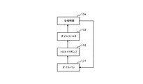
- FIG. 8 is a diagram showing an oil path using a trochoid pump.
- the trochoid pump 102 draws in oil accumulated in an oil pan 101 provided at the bottom of the engine from the suction port, pressurizes it, and discharges it from the discharge port.
- the oil discharged from the trochoid pump 102 is supplied to various mechanisms 104 through the oil filter 103. Thereafter, the oil is returned from each mechanism 104 to the oil pan 101.
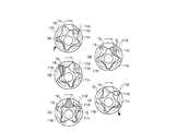
- FIG. 9 is a diagram for explaining the operation of the trochoid pump 102. This FIG. 9 is shown in FIG. 3 of Patent Document 1, and a process including suction and compression of oil mixed with air, discharge of air and part of oil, and discharge of oil is performed by one pump. Shown in the room. Further, the region filled with oil is indicated by hatching.
- the air discharge process starts from the state where the oil is sucked in the maximum. That is, as shown in FIG. 9D, the pump chamber starts to communicate with the discharge port 11d, and part of the mixed air and oil is discharged from the discharge port 11d through the passage 11d '.
- the discharge port 11d is closed and the discharge process is started.
- the remaining oil is discharged from the discharge port 11c and pumped toward the various mechanism portions 104.
- the maximum volume of oil discharged from the discharge port 11c is an area of the oil S compressed in the previous stroke, as shown in FIG. 9 (c).
- the technique which provides the discharge port connected to the pump outer side and discharges the air mixed in the oil is also disclosed in Patent Document 2, for example.
- the air discharge port is set between the suction port and the discharge port in order to set the air discharge step between the suction step and the discharge step.
- an internal gear pump such as a trochoid pump tends to separate oil to the outside and mixed air to the inside due to centrifugal force generated by the rotation of the outer rotor and inner rotor.
- the air discharge effect can be enhanced by providing it.
- the air discharge port communicates with the suction port, and air is sucked from the air discharge port due to negative suction pressure.
- the air discharge port communicates with the discharge port, and the discharge pressure escapes to the air discharge port due to the discharge pressure.
- the air discharge port communicates with either the suction port or the discharge port, as described above, the desired oil amount and oil pressure cannot be sucked and discharged, and the pump function is deteriorated. For this reason, it is simply not possible to provide a large air outlet on the inside.
- the air discharge port 220 is forced at a position where neither the suction port 210 nor the discharge port 230 communicates. If the design is large, the pump chamber 240 in the previous process and the pump chamber 250 in the next process communicate with each other via the air discharge port 220, and the discharge amount of the air-containing oil discharged from the air discharge port 220 is constant. In other words, there was a problem in that the oil discharge amount and discharge pressure varied, and the stable performance of the trochoid pump could not be obtained.
- the present invention has been made in order to solve such a problem, and does not communicate with any of the suction port and the discharge port, and allows the pump chamber in the previous process to communicate with the pump chamber in the next process.
- the purpose of the present invention is to increase the port area of the air discharge port, thereby enhancing the air discharge effect and reducing the torque of the rotor rotating shaft.
- a suction port for sucking oil in a suction process an air discharge port for discharging a part of air-mixed oil in a subsequent air discharge process of the suction process, and an air discharge
- the air discharge port is a first air exhaust provided on the inner peripheral side of the inscribed circle of the outer rotor.
- the outlet and the second air discharge port provided on the outer peripheral side from the circumscribed circle of the inner rotor are configured.
- the first air discharge port and the second air discharge port are provided in a state where they do not communicate with either the suction port or the discharge port, and the air discharge port is determined by the sum of the areas of both.
- the port area can be increased.
- the area of one air discharge port is not increased, but a large port area is secured by two air discharge ports provided at different positions. It is also possible to avoid the inconvenience that the pump chamber in the next process communicates.
- the port area of the air discharge port can be increased without communicating with either the suction port or the discharge port, and without connecting the pump chamber of the previous process and the pump chamber of the next process. While improving an effect, the torque of a rotor rotating shaft can be reduced.
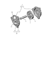
- FIG. 1 is an exploded perspective view showing a configuration example of a trochoid pump with an air discharge port according to the present embodiment.
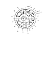
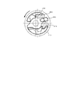
- FIG. 2 is a plan view showing a configuration example of the trochoid pump with an air discharge port according to the present embodiment.
- the trochoid pump with an air discharge port of the present embodiment includes a casing 1 composed of a body 1 a and a cover 1 b, an outer rotor 2 disposed rotatably in the casing 1, and an outer rotor 2.
- An inner rotor 3 that is rotatably disposed inside the outer rotor 2 and a shaft 4 that serves as a rotation axis of the outer rotor 2 and the inner rotor 3 are provided.
- the inner rotor 3 has four protrusions 3a to 3d, is directly connected to the shaft 4, and is supported so as to be rotatable in the direction of arrow A about the axis C1.
- the outer rotor 2 has five recesses 2a to 2e with which the protrusions 3a to 3d of the inner rotor 3 are engaged, and is slidably fitted to the cylindrical surface of the body 1a so as to be centered on the axis C2 in the direction of the arrow A. It is supported rotatably. That is, the trochoid pump with an air discharge port of this embodiment is a trochoid pump having four leaves and five nodes.
- the cover 1b of the casing 1 has a suction port 21 for sucking oil in the suction step, an air discharge port 22 for discharging a part of the air-mixed oil in the air discharge step subsequent to the suction step, and a step subsequent to the air discharge step. And a discharge port 23 for discharging oil in the discharge step.
- the air discharge port 22 is provided on the outer peripheral side of the first air discharge port 22-1 provided on the inner peripheral side with respect to the inscribed circle 31 of the outer rotor 2 and the circumscribed circle 32 of the inner rotor 3.
- a second air outlet 22-2 is preferably provided at a position closer to the circumscribed circle 32 on the outer peripheral side than the circumscribed circle 32 of the inner rotor 3 (for example, a position in contact with the circumscribed circle 32).
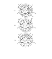
- FIG. 3 is a diagram illustrating an operation example of the trochoid pump with an air discharge port according to the present embodiment.
- FIG. 3 (a) shows a state after the inhalation process
- FIG. 3 (b) shows an air discharge process
- FIG. 3 (c) shows a state after the air discharge process.
- each state is indicated by one pump chamber, and a region filled with oil is indicated by oblique lines.
- FIG. 3A shows a state where the suction process is finished (a state immediately before the air discharge process is started).
- the pump chamber In the state shown in FIG. 3A, the pump chamber is not connected to the suction port 21 and the air discharge port 22, and the capacity is maximum.
- the air discharge port 22 is arranged such that the surface of the pump chamber on the side of the air discharge port 22 is located close to the air discharge port 22 when the suction process is completed. Is preferably formed.
- FIG. 3C shows a state where the air discharge process is completed (a state immediately before the discharge process is started). In the state shown in FIG. 3C, the pump chamber does not communicate with the air discharge port 22 or the discharge port 23, and the capacity is smaller than the maximum capacity shown in FIG.
- FIG. 3 shows a case where the discharge rate of the air-containing oil is 20%.
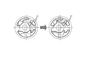
- FIG. 4 shows a configuration example of the air discharge port 22 when the discharge rate of the air-containing oil is set to 15%.
- FIG. 5 shows a configuration example of the air discharge port 22 when the discharge rate of the air-containing oil is set to 25%.
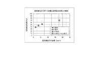
- FIG. 6 is a diagram illustrating the air discharge effect of the trochoid pump with the air discharge port according to the present embodiment.
- the air discharge effect is a ratio between the air content rate of oil before the air discharge step and the air content rate of oil discharged from the discharge port 23 after the air discharge step, and is calculated by the following equation. (1-Air content of oil discharged from trochoid pump with air discharge port / Air content of oil discharged from trochoid pump without air discharge port) x 100
- FIG. 6 shows the air discharge effect when a 20% oil-containing oil discharge rate is set in the ⁇ 54 rotor.
- ⁇ , ⁇ , and ⁇ indicate the air discharge effect of the prior art provided with only one air discharge port (corresponding to ⁇ 2, ⁇ 3, ⁇ 3.9) with different port areas.
- ⁇ indicates the air discharge effect when the first air discharge port 22 -1 (corresponding to ⁇ 3.9) and the second air discharge port 22 -2 (corresponding to ⁇ 5.5) are provided as in this embodiment. Show.
- the air discharge effect can be increased to some extent by increasing the port area of the air discharge port.
- there is a limit to increasing the port area of one air discharge port without communicating with either the suction port or the discharge port and without connecting the pump chamber of the previous process and the pump chamber of the next process. is there. That is, there is a limit to increasing the air discharge effect.
- ⁇ indicates the vicinity of the limit value.
- the suction port 21 and the discharge port 23 are indicated by ⁇ .
- the port area of the air exhaust port 22 (the first air exhaust port 22-1 and the second air is not communicated with the pump chamber of the previous process and the pump chamber of the next process).
- the total area of the discharge port 22-2 can be increased. Thereby, the air discharge effect can be increased as compared with the conventional case.
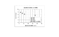
- FIG. 7 is a diagram illustrating the torque of the rotor rotation shaft in the trochoid pump with the air discharge port according to the present embodiment.
- FIG. 7 also shows the torque when a 20% air-containing oil discharge rate is set by the ⁇ 54 rotor.
- ⁇ , ⁇ , and ⁇ indicate the torque according to the prior art provided with only one air discharge port.
- ⁇ indicates the torque when the first air outlet 22 -1 and the second air outlet 22 -2 are provided as in this embodiment.
- the torque can be reduced to some extent by increasing the port area of the air discharge port.
- neither the suction port nor the discharge port is communicated, and the pump chamber of the previous process and the pump chamber of the next process are not communicated. Since there is a limit to this, there is a limit to reducing the torque.
- ⁇ indicates the vicinity of the limit value.
- the suction port 21 and the discharge port 23 are indicated by ⁇ .
- the port area of the air exhaust port 22 (the first air exhaust port 22-1 and the second air is not communicated with the pump chamber of the previous process and the pump chamber of the next process).
- the total area of the discharge port 22-2 can be increased. Thereby, a torque can be made small compared with the past. Also from this result, it can be seen that air is effectively discharged by providing the first air outlet 22 -1 and the second air outlet 22 -2 .
- Two air exhaust ports 22 -2 are provided, and the port area of the air exhaust port 22 can be increased by the sum of the areas of both.
- the area of one air discharge port is not increased as in the prior art, but a larger port area is provided by two air discharge ports 22 -1 and 22 -2 provided separately at different positions. Therefore, the inconvenience that the pump chamber in the previous process and the pump chamber in the next process communicate with each other via the air discharge port 22 can be avoided.
- the trochoid pump with the air discharge port of the present embodiment it is not possible to communicate with either the suction port 21 or the discharge port 23, and it is also possible to communicate the pump chamber of the previous process and the pump chamber of the next process. Therefore, the port area of the air discharge port 22 can be increased, the air discharge effect can be enhanced, and the torque of the rotor rotating shaft can be reduced.
Landscapes
- Engineering & Computer Science (AREA)
- Mechanical Engineering (AREA)
- General Engineering & Computer Science (AREA)
- Rotary Pumps (AREA)
- Details And Applications Of Rotary Liquid Pumps (AREA)
Abstract
空気混入のオイルの一部を排出するための空気排出口22を、アウターロータ2の内接円31よりも内周側に設けられた第1の空気排出口22-1と、インナーロータ3の外接円32より外周側に設けられた第2の空気排出口22-2とにより構成し、吸入口21および吐出口23の何れとも連通しない状態で第1の空気排出口22-1の面積と第2の空気排出口22-2の面積との合計により空気排出口22のポート面積を大きくすることができるようにするとともに、空気排出口22を介して前工程のポンプ室と次工程のポンプ室とが連通してしまう不都合も回避できるようにする。
Description
本発明は、空気排出口付きトロコイドポンプに関し、特に、内燃機関(エンジン)や変速機(ミッション)等に供給するオイルを吸入して圧送するトロコイド式のオイルポンプに用いて好適なものである。
一般に、内燃機関には、エンジン底部に設けられたオイルパンからその上方の各機構部にオイルを供給するためのオイルポンプが設けられている。例えば自動二輪車、船外機、スノーモービル等に用いられる4サイクルエンジンには、トロコイド型のオイルポンプ(トロコイドポンプ)が設けられることが多い(例えば、特許文献1参照)。また、トロコイドポンプは、変速機(ミッション)等へのオイル供給にも利用されることがある。
図8は、トロコイドポンプを用いたオイルの経路を示した図である。図8に示すように、トロコイドポンプ102は、エンジン底部に設けられたオイルパン101に溜まったオイルを吸入口から吸い込み、加圧して吐出口から排出する。トロコイドポンプ102から排出されたオイルは、オイルフィルタ103を介して種々の各機構部104に供給される。その後、オイルは各機構部104からオイルパン101に戻される。
図9は、トロコイドポンプ102の動作を説明するための図である。なお、この図9は、特許文献1の図3に示されたものであり、空気の混入したオイルの吸入および圧縮、空気および一部のオイルの排出、オイルの吐出からなる行程を1つのポンプ室にて示している。また、オイルが満たされた領域を斜線にて示している。
まず、インナーロータ13およびアウターロータ12が時計回りに回転することにより、図9(a)に示すように吸入口11bからオイルを吸入し始め、さらに時計回りに回転することにより、図9(b)に示すようにオイルをさらに吸入する。
次に、図9(c)に示すように、オイルが最大に吸入された状態から、空気排出行程に入る。すなわち、図9(d)に示すように、ポンプ室が排出口11dと連通し始め、混入した空気およびオイルの一部が排出口11dから通路11d’を通って排出される。
さらに、インナーロータ13およびアウターロータ12が時計回りに回転すると、排出口11dは閉鎖されて、吐出工程に移る。吐出工程では、図9(e)に示すように、残りのオイルが吐出口11cから吐出されて、種々の各機構部104に向けて圧送される。
ここで、吐出口11cから吐出されるオイルの最大容積は、図9(c)に示すように、前の行程で圧縮されたオイルSの領域となる。なお、ポンプ外側に連通する排出口を設けてオイルに混入した空気を排出する技術は、例えば特許文献2にも開示されている。
上記特許文献1,2に記載のように、従来のトロコイドポンプでは、吸入工程と吐出工程との間に空気排出工程を設定するため、空気排出口は吸入口と吐出口との間に設けられる。一般に、トロコイドポンプのような内接歯車ポンプではアウターロータおよびインナーロータの回転による遠心力によりオイルがより外側に、混入空気がより内側に分離される傾向となるので、空気排出口をより内側に設けた方が空気排出効果を高くすることができる。
しかし、空気排出口を単に内側に大きく設けるだけでは、空気排出口が吸入口に連通してしまい、吸入負圧により空気排出口から空気を吸い込んでしまう。もしくは、空気排出口が吐出口に連通してしまい、吐出圧力により空気排出口へ吐出圧力が逃げてしまう。空気排出口が、吸入口または吐出口のいずれに連通しても、上述の通り、所望のオイル量、オイル圧力を吸入・吐出することができず、ポンプ機能が低下してしまう。このため、単に空気排出口を内側に大きく設けることができない。
そのため、吸入口と吐出口との間の限られたスペースに空気排出口を設ける必要があり、ポート面積の確保に限界があった。よって、ポート面積が小さくなるため、空気排出効果を高くすることが難しいという問題があった。用途によっては一定の値以上の空気含有オイルの排出率が求められることもあるが、その空気含有オイルの排出率を実現するために必要なポート面積を確保することができないこともあった。また、空気排出口のポート面積が小さいと、排出抵抗が大きくなり、ロータ回転軸の回転に必要なトルクが高くなってしまうという問題もあった。
このような問題を解決するために、図10に示すように(この図では、ロータは反時計回りに回転)、吸入口210にも吐出口230にも連通しない位置において空気排出口220を無理に大きく設計すると、前工程のポンプ室240と次工程のポンプ室250とが空気排出口220を介して連通してしまい、空気排出口220から排出される空気含有オイルの排出量が一定とならず、オイルの吐出量・吐出圧力にばらつきが生じ、トロコイドポンプの安定した性能が得られなくなってしまうという問題があった。
本発明は、このような問題を解決するために成されたものであり、吸入口および吐出口の何れとも連通せず、また、前工程のポンプ室と次工程のポンプ室とを連通させることもなく空気排出口のポート面積を大きくすることができるようにして、空気排出効果を高めるとともにロータ回転軸のトルクを低減できるようにすることを目的とする。
上記した課題を解決するために、本発明では、吸入工程においてオイルを吸入する吸入口と、吸入工程の次の空気排出工程において空気混入のオイルの一部を排出する空気排出口と、空気排出工程の次の吐出工程においてオイルを吐出する吐出口とを備えた空気排出口付きトロコイドポンプにおいて、空気排出口を、アウターロータの内接円よりも内周側に設けられた第1の空気排出口と、インナーロータの外接円より外周側に設けられた第2の空気排出口とにより構成するようにしている。
上記のように構成した本発明によれば、吸入口および吐出口の何れとも連通しない状態で第1の空気排出口と第2の空気排出口とを設け、両者の面積の合計により空気排出口のポート面積を大きくすることができる。また、1つの空気排出口の面積を大きくするのではなく、異なる位置に分けて設けた2つの空気排出口により大きなポート面積を確保しているので、空気排出口を介して前工程のポンプ室と次工程のポンプ室とが連通してしまう不都合も回避することができる。これにより、吸入口および吐出口の何れとも連通せず、また、前工程のポンプ室と次工程のポンプ室とを連通させることもなく空気排出口のポート面積を大きくすることができ、空気排出効果を高めるとともに、ロータ回転軸のトルクを低減することができる。
以下、本発明の一実施形態を図面に基づいて説明する。図1は、本実施形態による空気排出口付きトロコイドポンプの構成例を示す分解斜視図である。また、図2は、本実施形態による空気排出口付きトロコイドポンプの構成例を示す平面図である。
図1に示すように、本実施形態の空気排出口付きトロコイドポンプは、ボディ1aおよびカバー1bから成るケーシング1と、ケーシング1内において回動自在に配置されたアウターロータ2と、アウターロータ2と協働してオイルの吸入および圧送を行うべくアウターロータ2の内側において回動自在に配置されたインナーロータ3と、アウターロータ2およびインナーロータ3の回転軸となるシャフト4とを備えている。
図2に示すように、インナーロータ3は、4個の突起3a~3dを有し、シャフト4に直結されて軸線C1を中心として矢印Aの方向に回動自在に支持されている。アウターロータ2は、インナーロータ3の突起3a~3dが噛み合う5個の凹み2a~2eを有し、ボディ1aの円筒面に摺動自在に嵌合されて軸線C2を中心として矢印Aの方向に回動自在に支持されている。すなわち、本実施形態の空気排出口付きトロコイドポンプは、4葉5節のトロコイドポンプである。
ケーシング1のカバー1bには、吸入工程においてオイルを吸入する吸入口21と、吸入工程の次の空気排出工程において空気混入のオイルの一部を排出する空気排出口22と、空気排出工程の次の吐出工程においてオイルを吐出する吐出口23とが設けられている。
ここで、空気排出口22は、アウターロータ2の内接円31よりも内周側に設けられた第1の空気排出口22-1と、インナーロータ3の外接円32より外周側に設けられた第2の空気排出口22-2とを含む。第2の空気排出口22-2は、インナーロータ3の外接円32より外周側で当該外接円32にできるだけ近い位置(例えば、外接円32に接する位置)に設けるのが好ましい。これにより、空気排出口22を吸入口21および吐出口23に連通させることなく、さらに前工程のポンプ室と次工程のポンプ室とが連通することなく空気排出口22を設けることが可能となる。
図3は、本実施形態による空気排出口付きトロコイドポンプの動作例を示す図である。図3(a)は吸入工程が終了した状態、図3(b)は空気排出工程の状態、図3(c)は空気排出工程が終了した状態を示している。なお、図3において、それぞれの状態を1つのポンプ室にて示し、オイルが満たされた領域を斜線にて示している。
まず、吸入工程では、アウターロータ2およびインナーロータ3が矢印Aの方向(反時計回り)に回転することにより、吸入口21からオイルを吸入する。図3(a)は、吸入工程が終了した状態(空気排出工程が開始する直前の状態)を示している。
この図3(a)に示す状態において、ポンプ室は吸入口21にも空気排出口22にも連通しておらず、容量が最大となっている。なお、ポンプ室の最大容量をできるだけ大きくするために、吸入工程が終了した時点でポンプ室の空気排出口22側の面が空気排出口22と近接する位置および形状となるように空気排出口22を形成するのが好ましい。
次に、図3(b)に示すように、ポンプ室にオイルが最大に吸入された状態からアウターロータ2およびインナーロータ3が反時計回りにさらに回転すると、空気排出行程に入り、ポンプ室が空気排出口22と連通する。これにより、混入した空気およびオイルの一部が空気排出口22から排出される。
さらに、アウターロータ2およびインナーロータ3が反時計回りに回転すると、空気排出口22は閉鎖されて、吐出工程に移る。吐出工程では、残りのオイルが吐出口23から吐出される。図3(c)は、空気排出工程が終了した状態(吐出工程が開始する直前の状態)を示している。この図3(c)に示す状態において、ポンプ室は空気排出口22にも吐出口23にも連通しておらず、容量は図3(a)に示す最大容量よりも小さくなっている。
ここで、図3(a)に示す空気排出工程開始前のポンプ室の容量をCP1、図3(c)に示す空気排出工程終了後のポンプ室の容量をCP2とした場合、(CP1-CP2)/CP1×100で空気含有オイルの排出率[%]が算出される。図3は、空気含有オイルの排出率が20%の場合を示している。
空気排出口22(第1の空気排出口22-1および第2の空気排出口22-2)の大きさ、位置、形状を変えることにより、空気含有オイルの排出率を調整することが可能である。図4は、空気含有オイルの排出率を15%に設定した場合における空気排出口22の構成例を示している。図5は、空気含有オイルの排出率を25%に設定した場合における空気排出口22の構成例を示している。
図6は、本実施形態による空気排出口付きトロコイドポンプの空気排出効果を示す図である。空気排出効果とは、空気排出工程前におけるオイルの空気含有率と、空気排出工程後に吐出口23から吐出したオイルの空気含有率との比率であり、以下の式により算出される。
(1-空気排出口付きトロコイドポンプの吐出オイルの空気含有率/空気排出口無しトロコイドポンプの吐出オイルの空気含有率)×100
(1-空気排出口付きトロコイドポンプの吐出オイルの空気含有率/空気排出口無しトロコイドポンプの吐出オイルの空気含有率)×100
図6は、φ54ロータにて20%の空気含有オイルの排出率を設定したときの空気排出効果を示したものである。◇、□、△はポート面積の異なる空気排出口(φ2相当、φ3相当、φ3.9相当)を1つのみ設けた従来技術による空気排出効果を示している。一方、○は本実施形態のように第1の空気排出口22-1(φ3.9相当)および第2の空気排出口22-2(φ5.5相当)を設けた場合の空気排出効果を示している。
図6に示すように、従来技術においても空気排出口のポート面積を大きくしていくことにより、空気排出効果をある程度は大きくすることができている。しかし、吸入口および吐出口の何れとも連通せず、また、前工程のポンプ室と次工程のポンプ室とを連通させることもなく、1つの空気排出口のポート面積を大きくするには限界がある。すなわち、空気排出効果を大きくすることに限界がある。△がその限界値付近を示している。
これに対して、本実施形態のように第1の空気排出口22-1および第2の空気排出口22-2を設けた場合には、○に示すように、吸入口21および吐出口23の何れとも連通せず、また、前工程のポンプ室と次工程のポンプ室とを連通させることもなく、空気排出口22のポート面積(第1の空気排出口22-1および第2の空気排出口22-2の合計面積)を大きくすることができる。これにより、従来に比べて空気排出効果を大きくすることができる。
図6の本試験結果により、インナーロータ3の外接円32より外周側に空気排出口22を設けた場合でも空気排出効果が得られることが認められた。したがって、吸入口21と空気排出口22、または吐出口23と空気排出口22とが同時に開口しない位置において、アウターロータ2の内接円31よりも内周側に設けられた位置と、インナーロータ3の外接円32より外周側に設けられた位置とに分割して空気排出口22を設けることで、ポンプ性能を落とすことなく、空気排出効果を高めることができる。
図7は、本実施形態による空気排出口付きトロコイドポンプにおけるロータ回転軸のトルクを示す図である。この図7も、φ54ロータにて20%の空気含有オイルの排出率を設定したときのトルクを示したものである。◇、□、△は空気排出口を1つのみ設けた従来技術によるトルクを示している。一方、○は本実施形態のように第1の空気排出口22-1および第2の空気排出口22-2を設けた場合のトルクを示している。
図7に示すように、従来技術においても空気排出口のポート面積を大きくしていくことにより、トルクをある程度は小さくすることができている。しかし、上述したように、吸入口および吐出口の何れとも連通せず、また、前工程のポンプ室と次工程のポンプ室とを連通させることもなく、1つの空気排出口のポート面積を大きくするには限界があるため、トルクを小さくすることに限界がある。△がその限界値付近を示している。
これに対して、本実施形態のように第1の空気排出口22-1および第2の空気排出口22-2を設けた場合には、○に示すように、吸入口21および吐出口23の何れとも連通せず、また、前工程のポンプ室と次工程のポンプ室とを連通させることもなく、空気排出口22のポート面積(第1の空気排出口22-1および第2の空気排出口22-2の合計面積)を大きくすることができる。これにより、従来に比べてトルクを小さくすることができる。この結果からも、第1の空気排出口22-1および第2の空気排出口22-2を設けることにより、空気排出が効果的に行われていることが分かる。
以上詳しく説明したように、本実施形態では、空気排出口22を、アウターロータ2の内接円31よりも内周側に設けられた第1の空気排出口22-1と、インナーロータ3の外接円32より外周側に設けられた第2の空気排出口22-2とにより構成したので、吸入口21および吐出口23の何れとも連通しない状態で第1の空気排出口22-1と第2の空気排出口22-2とを設け、両者の面積の合計により空気排出口22のポート面積を大きくすることができる。
また、本実施形態によれば、従来のように1つの空気排出口の面積を大きくするのではなく、異なる位置に分けて設けた2つの空気排出口22-1,22-2により大きなポート面積を確保しているので、空気排出口22を介して前工程のポンプ室と次工程のポンプ室とが連通してしまう不都合も回避することができる。
これにより、本実施形態の空気排出口付きトロコイドポンプによれば、吸入口21および吐出口23の何れとも連通せず、また、前工程のポンプ室と次工程のポンプ室とを連通させることもなく空気排出口22のポート面積を大きくすることができ、空気排出効果を高めるとともに、ロータ回転軸のトルクを低減することができる。
なお、上記実施形態は、何れも本発明を実施するにあたっての具体化の一例を示したものに過ぎず、これによって本発明の技術的範囲が限定的に解釈されてはならないものである。すなわち、本発明はその要旨、またはその主要な特徴から逸脱することなく、様々な形で実施することができる。
1 ケーシング
2 アウターロータ
3 インナーロータ
21 吸入口
22 空気排出口
22-1 第1の空気排出口
22-2 第2の空気排出口
23 吐出口
31 アウターロータの内接円
32 インナーロータの外接円
2 アウターロータ
3 インナーロータ
21 吸入口
22 空気排出口
22-1 第1の空気排出口
22-2 第2の空気排出口
23 吐出口
31 アウターロータの内接円
32 インナーロータの外接円
Claims (2)
- ケーシングと、
上記ケーシング内において回動自在に配置されたアウターロータと、
上記アウターロータと協働してオイルの吸入および圧送を行うべく上記アウターロータの内側において回動自在に配置されたインナーロータとを備え、
上記ケーシングは、吸入工程において上記オイルを吸入する吸入口と、上記吸入工程の次の空気排出工程において空気混入のオイルの一部を排出する空気排出口と、上記空気排出工程の次の吐出工程において上記オイルを吐出する吐出口とを有し、
上記空気排出口は、上記アウターロータの内接円よりも内周側に設けられた第1の空気排出口と、上記インナーロータの外接円より外周側に設けられた第2の空気排出口とを含むことを特徴とする空気排出口付きトロコイドポンプ。 - 上記第2の空気排出口は、上記インナーロータの外接円より外周側で当該外接円に近接する位置に設けられることを特徴とする請求項1に記載の空気排出口付きトロコイドポンプ。
Priority Applications (4)
| Application Number | Priority Date | Filing Date | Title |
|---|---|---|---|
| CN201480044570.9A CN105518301B (zh) | 2013-08-12 | 2014-08-11 | 带有空气排出口的次摆线泵 |
| ES14836947.3T ES2677997T3 (es) | 2013-08-12 | 2014-08-11 | Bomba trocoidal con puerto de descarga de aire |
| US14/910,260 US9784270B2 (en) | 2013-08-12 | 2014-08-11 | Trochoid pump with air ejection port |
| EP14836947.3A EP3034877B1 (en) | 2013-08-12 | 2014-08-11 | Trochoid pump with air discharge port |
Applications Claiming Priority (2)
| Application Number | Priority Date | Filing Date | Title |
|---|---|---|---|
| JP2013167303A JP6219093B2 (ja) | 2013-08-12 | 2013-08-12 | 空気排出口付きトロコイドポンプ |
| JP2013-167303 | 2013-08-12 |
Publications (1)
| Publication Number | Publication Date |
|---|---|
| WO2015022929A1 true WO2015022929A1 (ja) | 2015-02-19 |
Family
ID=52468315
Family Applications (1)
| Application Number | Title | Priority Date | Filing Date |
|---|---|---|---|
| PCT/JP2014/071162 Ceased WO2015022929A1 (ja) | 2013-08-12 | 2014-08-11 | 空気排出口付きトロコイドポンプ |
Country Status (6)
| Country | Link |
|---|---|
| US (1) | US9784270B2 (ja) |
| EP (1) | EP3034877B1 (ja) |
| JP (1) | JP6219093B2 (ja) |
| CN (1) | CN105518301B (ja) |
| ES (1) | ES2677997T3 (ja) |
| WO (1) | WO2015022929A1 (ja) |
Families Citing this family (2)
| Publication number | Priority date | Publication date | Assignee | Title |
|---|---|---|---|---|
| JP6570627B2 (ja) | 2015-05-18 | 2019-09-04 | 株式会社Tbk | 歯車ポンプ |
| JP7612501B2 (ja) * | 2021-04-26 | 2025-01-14 | 株式会社ミクニ | ポンプ装置 |
Citations (4)
| Publication number | Priority date | Publication date | Assignee | Title |
|---|---|---|---|---|
| JPH0465974U (ja) * | 1990-10-15 | 1992-06-09 | ||
| JPH09203308A (ja) | 1996-01-26 | 1997-08-05 | Kawasaki Heavy Ind Ltd | オイルポンプ |
| JP2011231772A (ja) | 2011-07-11 | 2011-11-17 | Mikuni Corp | オイルポンプ |
| WO2013115292A1 (ja) * | 2012-02-03 | 2013-08-08 | 株式会社ミクニ | オイルポンプ |
Family Cites Families (6)
| Publication number | Priority date | Publication date | Assignee | Title |
|---|---|---|---|---|
| JPH0465914A (ja) | 1990-07-02 | 1992-03-02 | Matsushita Electric Ind Co Ltd | 選局周波数設定装置 |
| JP4087309B2 (ja) * | 2003-07-25 | 2008-05-21 | 株式会社山田製作所 | トロコイド型オイルポンプ |
| WO2013127626A2 (de) * | 2012-02-27 | 2013-09-06 | Ixetic Bad Homburg Gmbh | Pumpenanordnung |
| CN104508301B (zh) * | 2012-08-28 | 2016-09-28 | 爱信艾达株式会社 | 齿轮泵 |
| JP6511730B2 (ja) * | 2014-05-23 | 2019-05-15 | 株式会社ジェイテクト | ポンプ |
| JP2015232293A (ja) * | 2014-06-10 | 2015-12-24 | トヨタ自動車株式会社 | 可変容量型オイルポンプ |
-
2013
- 2013-08-12 JP JP2013167303A patent/JP6219093B2/ja active Active
-
2014
- 2014-08-11 WO PCT/JP2014/071162 patent/WO2015022929A1/ja not_active Ceased
- 2014-08-11 ES ES14836947.3T patent/ES2677997T3/es active Active
- 2014-08-11 US US14/910,260 patent/US9784270B2/en active Active
- 2014-08-11 CN CN201480044570.9A patent/CN105518301B/zh active Active
- 2014-08-11 EP EP14836947.3A patent/EP3034877B1/en active Active
Patent Citations (4)
| Publication number | Priority date | Publication date | Assignee | Title |
|---|---|---|---|---|
| JPH0465974U (ja) * | 1990-10-15 | 1992-06-09 | ||
| JPH09203308A (ja) | 1996-01-26 | 1997-08-05 | Kawasaki Heavy Ind Ltd | オイルポンプ |
| JP2011231772A (ja) | 2011-07-11 | 2011-11-17 | Mikuni Corp | オイルポンプ |
| WO2013115292A1 (ja) * | 2012-02-03 | 2013-08-08 | 株式会社ミクニ | オイルポンプ |
Also Published As
| Publication number | Publication date |
|---|---|
| CN105518301A (zh) | 2016-04-20 |
| US20160186753A1 (en) | 2016-06-30 |
| CN105518301B (zh) | 2017-06-30 |
| US9784270B2 (en) | 2017-10-10 |
| JP6219093B2 (ja) | 2017-10-25 |
| EP3034877B1 (en) | 2018-05-30 |
| JP2015036517A (ja) | 2015-02-23 |
| EP3034877A4 (en) | 2017-01-25 |
| ES2677997T3 (es) | 2018-08-08 |
| EP3034877A1 (en) | 2016-06-22 |
Similar Documents
| Publication | Publication Date | Title |
|---|---|---|
| CN102889207B (zh) | 统一的可变排量油泵及真空泵 | |
| JP6422241B2 (ja) | オイルポンプ | |
| JP6128127B2 (ja) | ギヤポンプ | |
| KR100798055B1 (ko) | 가스베인펌프, 및 상기 펌프의 작동방법 | |
| JP5353383B2 (ja) | ルーツ式流体機械 | |
| JP5589532B2 (ja) | ベーンポンプ | |
| CN102365462B (zh) | 叶片泵 | |
| WO2007034888A1 (ja) | オイルポンプロータ | |
| JP4319617B2 (ja) | トロコイド型オイルポンプ | |
| JP6219093B2 (ja) | 空気排出口付きトロコイドポンプ | |
| CN103541899B (zh) | 螺旋压缩机 | |
| JP4289155B2 (ja) | ギヤポンプ | |
| CN104214091A (zh) | 车辆的吸油装置 | |
| CN216842226U (zh) | 压缩机及其气缸 | |
| JP5266583B2 (ja) | 内接歯車ポンプ | |
| JP2000265972A (ja) | 燃料ポンプ | |
| JP2003222090A (ja) | ベーン型真空ポンプ | |
| CN213684501U (zh) | 油泵 | |
| CN208718912U (zh) | 一种能减少磨损的外转子 | |
| JP3760298B2 (ja) | 複合型ギヤポンプ | |
| JP2019070373A (ja) | オイルポンプ | |
| TWI471487B (zh) | Screw Rotor Type Liquid Ring Compressor | |
| JPH06200887A (ja) | 回転真空ポンプ | |
| JP2022117255A (ja) | オイルポンプ | |
| JPS5851424Y2 (ja) | トロコイド式ブロワ−のアウタ−ロ−タ |
Legal Events
| Date | Code | Title | Description |
|---|---|---|---|
| 121 | Ep: the epo has been informed by wipo that ep was designated in this application |
Ref document number: 14836947 Country of ref document: EP Kind code of ref document: A1 |
|
| WWE | Wipo information: entry into national phase |
Ref document number: 14910260 Country of ref document: US Ref document number: 2014836947 Country of ref document: EP |
|
| NENP | Non-entry into the national phase |
Ref country code: DE |