WO2015029459A1 - 熱式流量センサ - Google Patents
熱式流量センサ Download PDFInfo
- Publication number
- WO2015029459A1 WO2015029459A1 PCT/JP2014/052381 JP2014052381W WO2015029459A1 WO 2015029459 A1 WO2015029459 A1 WO 2015029459A1 JP 2014052381 W JP2014052381 W JP 2014052381W WO 2015029459 A1 WO2015029459 A1 WO 2015029459A1
- Authority
- WO
- WIPO (PCT)
- Prior art keywords
- value
- flow rate
- flow sensor
- waveform
- correction
- Prior art date
- Legal status (The legal status is an assumption and is not a legal conclusion. Google has not performed a legal analysis and makes no representation as to the accuracy of the status listed.)
- Ceased
Links
Images







Classifications
-
- G—PHYSICS
- G01—MEASURING; TESTING
- G01F—MEASURING VOLUME, VOLUME FLOW, MASS FLOW OR LIQUID LEVEL; METERING BY VOLUME
- G01F1/00—Measuring the volume flow or mass flow of fluid or fluent solid material wherein the fluid passes through a meter in a continuous flow
- G01F1/68—Measuring the volume flow or mass flow of fluid or fluent solid material wherein the fluid passes through a meter in a continuous flow by using thermal effects
- G01F1/684—Structural arrangements; Mounting of elements, e.g. in relation to fluid flow
- G01F1/688—Structural arrangements; Mounting of elements, e.g. in relation to fluid flow using a particular type of heating, cooling or sensing element
- G01F1/69—Structural arrangements; Mounting of elements, e.g. in relation to fluid flow using a particular type of heating, cooling or sensing element of resistive type
- G01F1/692—Thin-film arrangements
-
- G—PHYSICS
- G01—MEASURING; TESTING
- G01F—MEASURING VOLUME, VOLUME FLOW, MASS FLOW OR LIQUID LEVEL; METERING BY VOLUME
- G01F1/00—Measuring the volume flow or mass flow of fluid or fluent solid material wherein the fluid passes through a meter in a continuous flow
- G01F1/68—Measuring the volume flow or mass flow of fluid or fluent solid material wherein the fluid passes through a meter in a continuous flow by using thermal effects
-
- G—PHYSICS
- G01—MEASURING; TESTING
- G01F—MEASURING VOLUME, VOLUME FLOW, MASS FLOW OR LIQUID LEVEL; METERING BY VOLUME
- G01F1/00—Measuring the volume flow or mass flow of fluid or fluent solid material wherein the fluid passes through a meter in a continuous flow
- G01F1/68—Measuring the volume flow or mass flow of fluid or fluent solid material wherein the fluid passes through a meter in a continuous flow by using thermal effects
- G01F1/696—Circuits therefor, e.g. constant-current flow meters
-
- G—PHYSICS
- G01—MEASURING; TESTING
- G01F—MEASURING VOLUME, VOLUME FLOW, MASS FLOW OR LIQUID LEVEL; METERING BY VOLUME
- G01F1/00—Measuring the volume flow or mass flow of fluid or fluent solid material wherein the fluid passes through a meter in a continuous flow
- G01F1/72—Devices for measuring pulsing fluid flows
-
- G—PHYSICS
- G01—MEASURING; TESTING
- G01F—MEASURING VOLUME, VOLUME FLOW, MASS FLOW OR LIQUID LEVEL; METERING BY VOLUME
- G01F5/00—Measuring a proportion of the volume flow
Definitions
- the present invention relates to a thermal flow sensor that measures the air flow rate based on the amount of heat released to air, and more particularly to a thermal flow sensor that is suitable for measuring the air flow rate taken into an internal combustion engine of an automobile.
- the thermal flow sensor that can detect the direction of the forward flow and the reverse flow can output the reverse flow waveform without inversion, so that the occurrence of the error can be suppressed.
- a general configuration of this thermal flow sensor is that a resistor and an insulating film are formed on a silicon substrate (wafer) using a semiconductor process as shown in Patent Document 2 and thinned by back surface etching. This is a high-speed response type flow sensor with reduced heat capacity.
- An object of the present invention is to provide a thermal flow sensor with improved measurement accuracy.
- a thermal flow sensor of the present invention has an air flow detection element having a diaphragm having a thin film portion on a semiconductor substrate, at least one heating resistor on the diaphragm, and A resistance temperature detector for detecting at least one temperature is formed on the upstream side and the downstream side of the heating resistor, and at least based on temperature difference information of the two resistance resistors on the upstream side and the downstream side.
- a correction circuit unit for processing as an output signal of the air flow rate detection element the waveform of the output signal processed by the correction circuit unit is an arbitrary predetermined value having a peak value of the waveform. When the value exceeds the predetermined value, the peak value is output so that a peak or a part of the valley part is cut to the predetermined value.
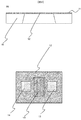
- a sensing element 20 of the thermal flow sensor is shown in FIG.
- the sensing element 20 is manufactured using semiconductor technology.
- silicon is removed from the back side of the silicon substrate 10 by etching to form a cavity.
- the laminated film 11 is formed so as to remain as a thin film portion.
- This thin film portion is referred to as a diaphragm 12.
- a heater 13 as a heating resistor is disposed at the center.
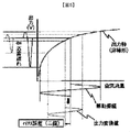
- the upstream temperature resistor 14 and the downstream temperature resistor 15 are arranged on the upstream and downstream sides of the heater 13. Arranged symmetrically. As a detection method, generally, the upstream temperature resistor 14 and the downstream temperature resistor 15 are connected in series and the intermediate potential (Eout) 16 is taken out as a flow signal (FIG. 3 ( a)). The relationship between the flow rate and Eout at this time is shown in FIG.
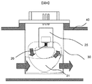
- FIG. 4 shows a schematic diagram of a thermal flow sensor on which the sensing element 20 is mounted.
- the sensing element 20 is mounted on a support substrate 25, and the support substrate 25 is bonded to the housing member 30, and has a bypass passage 31 for guiding a part of air in the intake duct 40 to the sensing element 20. Yes.
- the pulsating intake air reaches the thermal flow sensor.
- the pulsating frequency depends on the engine piston speed.
- the frequency of the pulsating flow is generally about 10 Hz to 200 Hz.
- a response delay occurs in the output of the sensing element 20 with respect to this pulsating flow.
- the authors have confirmed through experiments that a response delay occurs at a frequency of approximately 40 Hz or more in an element manufactured by semiconductor technology.
- a minus error lean error
- a bypass passage 31 for bypassing the air flow is provided as shown in FIG.
- a flow sensor is arranged at 31.
- the dust contained in the intake air is centrifuged, thereby reducing the amount of dust etc. reaching the sensing element 20 as well.
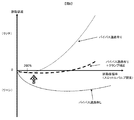
- the pulsation characteristic (error) of FIG. 6 such a bypass bypass passage system has a lean error due to a delay in response of the flow sensor during engine pulsation when there is no bypass passage (no bypass). End up. For this reason, as a method of returning the lean error to the zero reference (correcting to the rich side), the inertia of the air flowing through the bypass flow path is used.
- FIG. 7 shows an example of the configuration of the correcting means of the present invention.
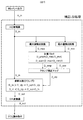
- An element output which is an output from the sensing element 20, is taken into the correction LSI and A / D converted by an internal A / D converter (D_in).
- the input values are recognized as D_max and D_min, respectively, through the maximum value detection circuit and the minimum value detection circuit.
- D_ave the average flow rate
- D_amp the flow rate amplitude
- D_clp A correction clamp value using these two output values as parameters is selected by the clamp correction map.
- the original input value can be prevented from becoming larger than the correction clamp value. That is, when the original input value (D_in) and the corrected clamp value (D_clp) are compared, and the corrected clamp value (D_clp) does not exceed, the original input value (D_in) is a value calculated by comparison in waveform comparison. On the other hand, if the correction clamp value (D_clp) is exceeded, the correction clamp value (D_clp) is output as a value (D_out) that is comparatively calculated by waveform comparison.
- the arbitrary predetermined value is output, and the predetermined value is the maximum value of the waveform amplitude ( Alternatively, cutting the peak (or valley) of the output waveform with an arbitrary predetermined value is hereinafter referred to as “clamp”, and such correction is referred to as “clamp correction”.
- the comparatively calculated value (D_out) is D / A converted, output as an output signal of the flow sensor, and read by the ECU.
- FIG. 8 shows a state where the pulsation amplitude rate is 200% or more (the pulsation amplitude is in the reverse flow region).
- the solid line in FIG. 8 shows the pulsation waveform in the actual intake duct, and this average value (thick one-dot chain line) is a true value.
- the value obtained by A / D converting the element output of the flow sensor becomes a dotted waveform of D_in in FIG.
- This dotted waveform has a response delay with respect to true air pulsation, the amplitude is small, and the average value of the whole is greatly shifted in the positive error direction due to the inertia effect due to bypass bypass Is shown.
- the average value of D_in indicates a rich error as a pulsation error.
- D_in For the input value D_in, D_max and D_min are recognized by the maximum value and minimum value detection circuits, respectively.
- the average flow rate (D_ave) and the flow rate amplitude (D_amp) are calculated from these values, and a correction clamp value (D_clp) is selected from the clamp correction map inside the LSI.
- D_in is then compared with D_clp to derive the D_out output.
- the average value of D_out at this time is cut as the waveform at the top of the waveform, so that the average value becomes low and can be close to the true air average flow rate value.
- a thermal flow sensor can be provided.
- the values obtained by the maximum value and minimum value detection circuit are set to be updated or attenuated at certain times.
- FIG. 16 and FIG. 17 show respective correction waveforms when noise is mixed.
- FIG. 16A shows a waveform when noise is mixed in the element output (D_in), and the minimum value detected by the LSI at this time differs from the value recognized before and after the noise is mixed. Accordingly, a value (D_clp2) having a different clamp value is applied. However, when correcting by clamping, since the original waveform remains as long as the original waveform does not exceed the clamp value, only a part where an error occurs is sufficient.
- the output waveform is D_out in FIG.
- FIG. 17 similarly shows a waveform when noise is mixed in the element output (D_in).
- the minimum value detected by the LSI is different from the value recognized before and after the noise is mixed.
- a value ( ⁇ x2) having a different correction value is applied.
- the output waveform when adding the correction amounts always adds the correction amounts, so that an error [( ⁇ x1) ⁇ ( ⁇ x2)] always occurs in all the waveforms, and the correction accuracy is improved. It may get worse.
- the correction error is smaller in the method of correcting by clamping.
- the example in which the peak portion of the pulsation waveform is clamped in order to reduce the rich error as shown in FIG. 6 has been described.
- the valley portion of the pulsation waveform has been described. Obviously, if clamped, the lean error can be reduced as well.
- a thermal flow sensor with low output signal pulsation error and improved noise correction accuracy is provided. it can.
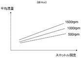
- FIG. 10A is a graph simply showing the throttle valve opening and the average value of the air pulsation flowing at that time. As the throttle opening is increased, the average flow rate flowing through the duct increases. The average flow rate depends on the engine speed at that time. The engine speed directly depends on the frequency of the pulsation waveform.
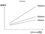
- FIG. 10B shows a graph simply showing the opening degree of the throttle valve and the pulsation amplitude rate of the air pulsation flowing at that time.
- the pulsation amplitude rate is calculated by the following equation (1).
- air pulsation in an actual vehicle engine is a physical phenomenon that depends on “frequency”, “average flow rate”, and “pulsation amplitude rate (pulsation amplitude)”.
- the combination of these three parameters determines the error of the flow meter. That is, under each pulsation condition, if each parameter can be read correctly inside the sensor, that is, by the correction LSI, correction according to the parameter can be performed.
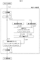
- FIG. 7 is different from FIG. 7 in that correction processing by HPF is performed after A / D conversion by the A / D converter.
- HPF correction processing by HPF
- the output waveform (output amplitude) attenuated by the response delay is corrected so as to approach the true air pulsation amplitude.
- the lean error due to the response delay depending on the frequency is eliminated. That is, the dependency of the “frequency” which is one of the three parameters on the pulsation error is reduced.
- the clamp correction value required for correction is reduced from the three-dimensional map to the two-dimensional map, the cost increase of the LSI is improved.
- the clamp correction value is determined using the detected average value and the pulsation amplitude amount as parameters, and therefore, in a DC waveform in which pulsation does not occur, the amplitude amount is almost zero.
- the clamp correction value is set to a much larger value, the correction is not performed at all and the influence on the static characteristics can be made zero.
- the feature of this correction is that there is no correction effect under the static characteristic conditions that do not require correction, and that effective correction is applied only under the dynamic characteristic conditions that require correction.
- the frequency response compensation represented by HPF and the like is added to reduce the frequency dependency.
- the pulsation error caused by the bypass structure represented by the inertia effect and the like is described.
- the pulsation can be corrected by the correction method as shown in FIG.
- FIG. 14 shows an example of a configuration for recognizing values detected by the maximum value and minimum value detection circuit with higher accuracy with respect to the correction method.
- FIG. 14 is based on the correction method of the second embodiment, but the same applies to other embodiments. As shown in FIG. 14, in this embodiment, the signal after the response delay compensation by the HPF is corrected by the linear conversion circuit. Details of this correction will be described with reference to FIG.
- the output of the sensor element 20 has a non-linear curve relationship with the air flow rate as shown in FIG. Therefore, the output value (D_in) when there is no curvature correction has a characteristic with a curvature as shown in the figure.
- the LSI detects the amplitude amount (Va) as a different value, so that the correction accuracy decreases. End up.
Landscapes
- Physics & Mathematics (AREA)
- Fluid Mechanics (AREA)
- General Physics & Mathematics (AREA)
- Measuring Volume Flow (AREA)
Abstract
計測精度を向上した熱式流量センサを提供するために、半導体基板に薄膜部を備えたダイアフラムを有する空気流量検出素子と、前記ダイアフラム上に少なくとも一つの発熱抵抗体を有し、かつ、前記発熱抵抗体の上流側と下流側に少なくとも一つずつの温度を検出する測温抵抗体が形成されており、少なくとも上流側と下流側の二つの前記測温抵抗体の温度差情報に基づいて前記空気流量検出素子の出力信号として処理する補正回路部と、を有する熱式流量センサにおいて、前記補正回路部で処理される出力信号の波形は、波形のピーク値がある任意の所定値を超えた時に前記所定値が出力されることでピーク値を成す山部あるいは谷部の一部を前記所定値にカットした波形であるように構成した。
Description
本発明は、空気への放熱量を基に空気流量を測定する熱式流量センサに係り、特に、自動車の内燃機関エンジンに吸入される空気流量を測定する際に好適な熱式流量センサに関する。
従来から、この種の空気流量を測定する装置としては、種々の構成や方式のものが実用に供されてきたが、エンジンの高性能化に伴う流量測定の高精度化要求により、特にエンジン脈動時のセンサ誤差を低減するため、流量センサの逆流検知方式が検討されてきた。従来は、特許文献1に代表されるようなボビン式の流量センサが主流であったが、順流、逆流問わず特性がプラス方向に変化してしまうため、逆流が発生するような脈動条件においては、ボビン式の流量センサではリッチ誤差(平均流量が高くなってしまう誤差)が発生する(図1参照)。
これに対し、順流と逆流の方向を検知できる熱式流量センサは逆流波形が反転することなく出力されるため前記誤差の発生を抑制できる。この熱式流量センサの一般的な構成は、特許文献2に示されるような、半導体プロセスを用いて、シリコン基板(ウエハ)に抵抗体および絶縁膜を形成し、裏面エッチングにより薄膜化することによって熱容量を抑えた高速応答型流量センサである。
しかしながら、特許文献2に示されるような流量センサにおいても、エンジン脈動のような100Hzを超えるような高周波脈動においては応答遅れが発生し、特許文献1に明記されているようなマイナス誤差(2値化現象)(以下、「リーン誤差」と称す。)が発生してしまう。これを対策する手法として、慣性効果を効かせてリーン誤差を相殺させるように、バイパス通路構造を設計するのが主流である。
バイパス設計において、エンジン脈動が200%以上(=逆流が発生する脈動条件)の脈動振幅が発生する領域においては、200%以下の脈動振幅の領域の誤差を低減させるために設計したバイパス構造においては、逆流発生時にバイパス通路内に逆流を取り込みにくくなってしまい、200%以上の高脈動振幅域において、リッチ誤差を発生させてしまう傾向にあることを筆者らは知見を得ている。
つまり、流量センサの応答遅れによるリーン誤差と、バイパス通路の慣性効果によるリッチ誤差が相殺する脈動振幅領域には制限がある。近年、燃費向上を目的としたVTCエンジンを代表するエンジン環境では、1000%近くの脈動振幅が発生し、従来の流量センサでは、リッチ誤差が大きくなってしまう特定の脈動振幅条件が発生してしまうといった課題がある。
本発明の目的は、計測精度を向上した熱式流量センサを提供することにある。
上記課題を解決するために、本発明の熱式流量センサは、半導体基板に薄膜部を備えたダイアフラムを有する空気流量検出素子と、前記ダイアフラム上に少なくとも一つの発熱抵抗体を有し、かつ、前記発熱抵抗体の上流側と下流側に少なくとも一つずつの温度を検出する測温抵抗体が形成されており、少なくとも上流側と下流側の二つの前記測温抵抗体の温度差情報に基づいて前記空気流量検出素子の出力信号として処理する補正回路部と、を有する熱式流量センサにおいて、前記補正回路部で処理される出力信号の波形は、波形のピーク値がある任意の所定値を超えた時に前記所定値が出力されることでピーク値を成す山部あるいは谷部の一部を前記所定値にカットした波形であるように構成した。
本発明によれば、計測精度を向上した熱式流量センサを提供することが可能となる。
以下、本発明の実施の形態を説明する。
まず、熱式流量センサの概略について説明する。熱式流量センサのセンシングエレメント20を図2に示す。センシングエレメント20は半導体技術を用いて製造される。シリコン基板(ウエハ)10に酸化膜や窒化膜の絶縁膜、抵抗体を積層してなる積層膜11を形成した後、シリコン基板10の裏面側からエッチングによりシリコンを除去して空洞部を形成する。このとき、積層膜11が薄膜部として残るように形成される。この薄膜部をダイアフラム12と呼ぶ。このダイアフラム12上には、中心部に加熱抵抗体のヒータ13が配置され、このヒータ13の上流側および下流側に上流側温抵抗体14、下流側温抵抗体15がヒータ13に対して左右対称に配置される。検出方法としては、一般的には上流側温抵抗体14と下流側温抵抗体15を直列に接続し、その中間電位(Eout)16を流量信号として取り出すのが一般的である(図3(a)参照)。なお、この時の流量とEoutの関係を図3(b)に示している。
次に、上記センシングエレメント20が搭載される熱式流量センサの概略図を図4に示す。
センシングエレメント20は支持基板25上に搭載され、その支持基板25はハウジング部材30に接着されており、吸気ダクト40の一部の空気をセンシングエレメント20へ誘導するためのバイパス通路31を有している。
センシングエレメント20は支持基板25上に搭載され、その支持基板25はハウジング部材30に接着されており、吸気ダクト40の一部の空気をセンシングエレメント20へ誘導するためのバイパス通路31を有している。
このような実装環境下において、熱式流量センサに脈動した吸入空気が到達する。脈動する周波数はエンジンのピストン回転数に依存する。脈動流の周波数は10Hz~200Hz程度が一般的である。この脈動流に対して、センシングエレメント20の出力には応答遅れが発生する。特に半導体技術で製造されたエレメントにおいては、概ね40Hz以上の周波数において応答遅れが発生することを筆者らは実験により確認している。ここで応答遅れが発生した場合、空気流量と出力信号の非線形性の特性から、マイナス誤差(リーン誤差)が発生してしまう(図5参照)。
これに対して、近年では、熱式流量センサの応答遅れによるリーン誤差を改善する努力が払われた結果、図4に示されるように空気の流れを迂回させるバイパス通路31を設け、このバイパス通路31に流量センサを配置している。なお、取り込んだ吸入空気を迂回させることで吸入空気に含まれるダスト等を遠心分離し、これによりセンシングエレメント20へのダスト等の到達量も併せて低減している。このような迂回バイパス通路方式は、図6の脈動時特性(誤差)に示すように、バイパス通路がない状態(バイパス無し)のときには、エンジン脈動時に流量センサの応答遅れによりリーン誤差が発生してしまう。このため、リーン誤差をゼロ基準まで戻す(リッチ側へ補正する)手法として、バイパス流路を流れる空気の慣性を利用するものである。
しかしながら、この迂回バイパス通路構造の慣性効果を利用しても、図6に示すような逆流が発生する脈動振幅率(200%)以下の低脈動振幅域においては、脈動誤差をゼロに近づける有効な手段ではあるが、200%以上の高脈動振幅域においては、今度はリッチ誤差の傾向が強くなり、低域から高域までの範囲を全てカバーすることが非常に難しいといった課題がある。
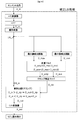
本発明の補正手段の一構成例を図7に示す。センシングエレメント20からの出力であるエレメント出力は補正LSI内部に取り込まれ、内部のA/D変換器によってA/D変換される(D_in)。この入力値は最大値検出回路および、最小値検出回路を通ることにより、それぞれD_max、D_minとして認識される。この二つの出力値は計算ブロックで平均流量(D_ave)と流量振幅(D_amp)の値が算出される。この二つの出力値をパラメータとした補正クランプ値(D_clp)がクランプ補正マップにより選択される。この補正クランプ値(D_clp)と、元の入力値(D_in)とを比較計算することによって、元の入力値が補正クランプ値よりも大きくならないようにすることができる。すなわち、元の入力値(D_in)と補正クランプ値(D_clp)を比較したときに、補正クランプ値(D_clp)を超えない場合は、元の入力値(D_in)が波形比較で比較計算された値(D_out)として出力される、一方で、補正クランプ値(D_clp)を超える場合は、補正クランプ値(D_clp)が波形比較で比較計算された値(D_out)として出力される。なお、入力値がある任意の所定値(ここでは、補正クランプ値に対応する。)を超えたときに、その任意の所定値を出力し、かつ、その所定値が波形の振幅の最大値(あるいは最小値)となるように設定して、出力波形の山(あるいは谷)をある任意の所定値でカットすることを以降ではクランプとよび、そのような補正をクランプ補正と呼ぶ。
比較計算された値(D_out)はD/A変換されて流量センサの出力信号として出力されECUで読み取られる。
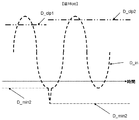
次に、上述した補正手段における効果について図8および図9を用いて説明する。まず図8は、脈動振幅率が200%以上(逆流域まで脈動振幅している)の状態を示している。図8の実線は、実際の吸気ダクト内の脈動波形を示しており、この平均値(太い一点鎖線)が真の値となる。これに対し、流量センサのエレメント出力をA/D変換した値は図8のD_inの点線波形となる。この点線波形は真の空気脈動に対して応答遅れが発生し、振幅が小さくなっており、かつ、バイパス通路の迂回による慣性効果により全体の平均値が大幅にプラス誤差方向にシフトしている波形を示している。これにより、D_inの平均値(細い一点鎖線)は脈動誤差としてはリッチ誤差を示している。
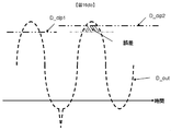
一方、LSI内部で補正した場合について図9を用いて説明する。入力値であるD_inに対して、最大値、最小値検出回路でそれぞれD_maxとD_minが認識される。これらの値から平均流量(D_ave)と流量振幅(D_amp)の値が算出され、LSI内部のクランプ補正マップからある補正クランプ値(D_clp)が選択される。その後、D_inはD_clpと比較計算されてD_out出力が導き出される。この時のD_outの平均値は図9に示すように、波形の上部の波形がカットとされたため平均値としては、低くなり真の空気平均流量値に近づけることができ、より誤差の少ない高精度な熱式流量センサを提供することができる。また上記最大値、最小値検出回路で得られる値は、ある時刻毎で更新されるか、減衰するように設定される。
次に、本実施例で波形をクランプしている利点について説明する。波形を補正する方法として、クランプのように、波形の一部をカットして補正をかける場合と、波形自体に補正量自体を足し合わせることによって補正する方法の大きく2種類に分類される。通常の脈動波形を補正する場合は、共に有効な補正方法であると考えられる。しかしながら、エンジン脈動においては、常に安定した脈動波形が得られるとは限らず、ノイズが混入した波形になってしまう場合がある。ここでノイズが混入した場合における、それぞれの補正波形を図16、図17に示す。
まず、クランプして補正する方式について図16を用いて説明する。
図16(a)はエレメント出力(D_in)にノイズが混入した場合の波形を示しており、この時にLSIで検知される最小値はノイズが混入する前と後で認識する値が異なってしまう。これによって、クランプ値が異なる値(D_clp2)が適応される。しかしながら、クランプして補正をかける場合は、元の波形がクランプ値を超えない限りは元の波形のままであるため、誤差が発生する部分が一部で済む。その出力波形が図17(b)のD_outとなる。
これに対して補正量を加える方式について図17を用いて説明する。
図17は同様にエレメント出力(D_in)にノイズが混入した場合の波形を示しており、この時にLSIで検知される最小値はノイズが混入する前と後で認識する値が異なってしまう。これによって、補正値が異なる値(-x2)が適応される。補正量をたし合わせる場合の出力波形を図17に示すように、常に補正量をたし合わせるため波形全てに誤差[(-x1)-(-x2)]分が常に発生し、補正精度が悪化してしまう場合がある。
図17は同様にエレメント出力(D_in)にノイズが混入した場合の波形を示しており、この時にLSIで検知される最小値はノイズが混入する前と後で認識する値が異なってしまう。これによって、補正値が異なる値(-x2)が適応される。補正量をたし合わせる場合の出力波形を図17に示すように、常に補正量をたし合わせるため波形全てに誤差[(-x1)-(-x2)]分が常に発生し、補正精度が悪化してしまう場合がある。
したがって、波形にノイズが混入するような場合において、クランプして補正する方式の方が、補正誤差が小さくなる。
また、本実施例は図6に示すようなリッチ誤差を低減するために、脈動波形の山部をクランプする実施例を説明したが、リーン誤差を低減するためには、脈動波形の谷部をクランプすれば、リーン誤差が同様に低減できることは明白である。
以上より、例えば燃費向上を目的としたVTCエンジンを代表する高脈動振幅が発生するエンジン環境においても、出力信号の脈動誤差が低く、また、ノイズに対する補正精度を向上させた熱式流量センサを提供できる。
次に、本発明の他の一構成例について説明する。
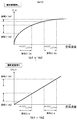
まず、クランプ補正値が平均流量と振幅値の二つのパラメータから決定されることについて説明する。図10(a)、(b)を用いて実車エンジンでの脈動挙動について説明する。図10(a)はスロットルバルブの開度とその時に流れる空気脈動の平均値を簡易的に示したグラフを示す。スロットル開度を大きくしていくと、ダクト内を流れる平均流量が大きくなる。また平均流量は、その時のエンジン回転数に依存する。また、エンジン回転数はそのまま脈動波形の周波数に依存する。
次に、図10(b)はスロットルバルブの開度とその時に流れる空気脈動の脈動振幅率を簡易的に示したグラフを示す。なお、脈動振幅率は以下の式(1)で算出される。
(脈動振幅率)=(脈動振幅量)/(平均流量) (1)
図10(b)に示されるように、スロットル開度を大きくしていくと空気脈動の脈動振幅率が大きくなる。また平均流量は、その時のエンジン回転数に依存する。
図10(b)に示されるように、スロットル開度を大きくしていくと空気脈動の脈動振幅率が大きくなる。また平均流量は、その時のエンジン回転数に依存する。
以上より、実車エンジンにおける空気脈動は、「周波数」、「平均流量」、そして「脈動振幅率(脈動振幅量)」に依存した物理現象である。この3つのパラメータの組合せによって、流量計の誤差が決まることになる。つまり、各脈動条件において、センサ内部で、つまり補正LSIで各パラメータを正しく読み取ることができれば、それに応じた補正が可能となる。
しかしながら、3つのパラメータを持つということは、補正値を3次元で持つことになり、補正LSI内部の補正値マップ、および計算ステップが過大に必要となり、コストが高くなってしまう。
そこで筆者らは、HPF(High Pass Filter)などの周波数応答補償と、上記補正(図7)とを組合せることにより、より補正精度が高く、そしてLSIのコストダウンを図った。この構成について図11に示す。
図7との異なる点は、A/D変換器でのA/D変換後にHPFによる補正処理を行うことである。HPFによる補正処理を通すことによって、応答遅れによって減衰した出力波形(出力振幅)が真の空気脈動振幅に近づくように補正される。これにより、周波数に依存した応答遅れによるリーン誤差が解消される。つまり、3つのパラメータのうちの一つである「周波数」の脈動誤差の依存性が低減される。これによって、残りのパラメータである「平均流量」と「脈動振幅量」に応じた補正を入力信号に与えれば、より高精度な脈動補正が可能となる。そして補正に必要なクランプ補正値が3次元マップから2次元マップへ低減されたため、LSIのコストアップが改善される。
また、本実施例によれば、クランプ補正値は検出される平均値と脈動振幅量をパラメータとして決定されるため、脈動が発生しないようなDC波形においては、振幅量がほぼゼロとなるため、振幅量がゼロのような小さな値の場合は、クランプ補正値をはるかに大きな値に設定しておけば、全く補正がかからず静特性への影響をゼロにすることができる。つまり、本補正の特徴は、補正をかける必要がない静特性の条件においては、全く補正影響が無く、かつ、補正が必要な動特性の条件でのみ有効な補正がかかるといった特徴を持つ。
また、本実施例では、周波数の依存性を低減するためにHPFなどを代表とした周波数応答補償を加えた説明をしたが、前記、慣性効果などを代表としたバイパス構造に起因した脈動誤差を低減する手法により、応答遅れによるリーン誤差を補正しなくても良い場合は、図7に示すような補正手法により、脈動補正が可能となる。
ただし、誤差自体はバイパス構造により低減されるが、エレメント出力自体は、応答遅れにより高周波脈動における波形は、真の脈動振幅量から減衰した波形のままである。その場合、波形の最大値および最小値が正しく認識できず、その脈動条件に適した補正ができない場合がある。それを解決するための補正方法の一例の構成について図13を用いて説明する。
入力信号にはHPF補正を通さないことによって、脈動誤差のリッチ化を防止し、かつ、波形の最大値、最小値は真の脈動振幅量に近い値を検知する必要があるため、最大値、最小値検出の入力のみHPFを通すことによって波形の減衰が改善され、より高精度に上記ピーク値を認識できる。これによって、脈動条件を正しく認識することによって高精度な補正が可能となる。
これによって、図6に示すような、高脈動域においてもリッチ誤差を低減した高精度な熱式流量センサが提供できる。
また、上記補正方法に対して、最大値、最小値検出回路で検出される値をさらに高精度に認識する一構成例について図14に示す。
図14は実施例2の補正方法を基準にしているが、その他の実施例においても同様である。図14に示されるように、本実施例ではHPFによる応答遅れ補償を行なった後の信号を線形変換回路にて補正を行なう構成である。この補正の詳細について図15を用いて説明する。
センサエレメント20の出力は図15に示されるように、空気流量に対して非線形曲線の関係にある。そのため、曲がり補正がない場合の出力値(D_in)は図のような曲がりを持った特性となる。この場合、脈動波形の振幅量(Qa)が同じで平均流量が異なる場合、平均流量が異なると、LSIでは振幅量(Va)がそれぞれ異なった値として検出されるため、補正の精度が低下してしまう。
それに対して、線形変換補正を入れると、脈動波形の平均流量が変化した場合でも、振幅量を正しく検出することができる。これによって、高精度な補正が可能となる。
10・・・シリコン基板
11・・・絶縁膜と抵抗体の積層膜
12・・・ダイアフラム
13・・・ヒータ
14・・・上流側温抵抗体
15・・・下流側温抵抗体
16・・・中間電位
20・・・センシングエレメント
25・・・支持基板
30・・・ハウジング部材
40・・・吸気ダクト
11・・・絶縁膜と抵抗体の積層膜
12・・・ダイアフラム
13・・・ヒータ
14・・・上流側温抵抗体
15・・・下流側温抵抗体
16・・・中間電位
20・・・センシングエレメント
25・・・支持基板
30・・・ハウジング部材
40・・・吸気ダクト
Claims (6)
- 半導体基板に薄膜部を備えたダイアフラムを有する空気流量検出素子と、前記ダイアフラム上に少なくとも一つの発熱抵抗体を有し、かつ、前記発熱抵抗体の上流側と下流側に少なくとも一つずつの温度を検出する測温抵抗体が形成されており、少なくとも上流側と下流側の二つの前記測温抵抗体の温度差情報に基づいて前記空気流量検出素子の出力信号として処理する補正回路部と、を有する熱式流量センサにおいて、
前記補正回路部で処理される出力信号の波形は、波形のピーク値がある任意の所定値を超えた時に前記所定値が出力されることでピーク値を成す山部あるいは谷部の一部を前記所定値にカットした波形であることを特徴とする熱式流量センサ。 - 請求項1に記載の熱式流量センサにおいて、
前記任意の所定値は、前記空気流量検出素子の出力信号を元にした信号から求められる平均流量と振幅値の二つのパラメータから決定することを特徴とする熱式流量センサ。 - 請求項2に記載の熱式流量センサにおいて、
前記平均流量と前記振幅値は、前記空気流量検出素子の出力信号を元にした信号から、最大値を検出する回路と最小値を検出する回路から検出される各々の値を用いて求められることを特徴とする熱式流量センサ。 - 請求項3に記載の熱式流量センサにおいて、
前記空気流量検出素子の出力信号を元にした信号は、前記空気流量検出素子の出力信号に応答遅れを補償する回路で補正された信号であることを特徴とする熱式流量センサ。 - 請求項3から請求項5のいずれかに記載の熱式流量センサにおいて、
前記出力信号は、周波数応答回路による補正処理がされていることを特徴とする物理量センサ。 - 請求項3から請求項5のいずれかに記載の熱式流量センサにおいて、
前記最大値を検出する回路および最小値を検出する回路に入力される信号は、前記出力信号を流量と出力の関係で線形方向に補正した信号であることを特徴とする物理量センサ。
Priority Applications (3)
| Application Number | Priority Date | Filing Date | Title |
|---|---|---|---|
| EP14840664.8A EP3043155B1 (en) | 2013-09-02 | 2014-02-03 | Thermal flow sensor |
| CN201480048418.8A CN105518420B (zh) | 2013-09-02 | 2014-02-03 | 热式流量传感器 |
| US14/914,709 US10190899B2 (en) | 2013-09-02 | 2014-02-03 | Thermal flow sensor |
Applications Claiming Priority (2)
| Application Number | Priority Date | Filing Date | Title |
|---|---|---|---|
| JP2013-180852 | 2013-09-02 | ||
| JP2013180852A JP6106559B2 (ja) | 2013-09-02 | 2013-09-02 | 熱式流量センサ |
Publications (1)
| Publication Number | Publication Date |
|---|---|
| WO2015029459A1 true WO2015029459A1 (ja) | 2015-03-05 |
Family
ID=52586046
Family Applications (1)
| Application Number | Title | Priority Date | Filing Date |
|---|---|---|---|
| PCT/JP2014/052381 Ceased WO2015029459A1 (ja) | 2013-09-02 | 2014-02-03 | 熱式流量センサ |
Country Status (5)
| Country | Link |
|---|---|
| US (1) | US10190899B2 (ja) |
| EP (1) | EP3043155B1 (ja) |
| JP (1) | JP6106559B2 (ja) |
| CN (1) | CN105518420B (ja) |
| WO (1) | WO2015029459A1 (ja) |
Families Citing this family (13)
| Publication number | Priority date | Publication date | Assignee | Title |
|---|---|---|---|---|
| JP6177384B1 (ja) * | 2016-05-26 | 2017-08-09 | 三菱電機株式会社 | 熱式空気流量計 |
| WO2018074120A1 (ja) * | 2016-10-19 | 2018-04-26 | 日立オートモティブシステムズ株式会社 | 流量検出装置 |
| JP6540743B2 (ja) * | 2017-03-30 | 2019-07-10 | 株式会社デンソー | 空気量算出装置 |
| JP6531774B2 (ja) * | 2017-04-14 | 2019-06-19 | 株式会社デンソー | 空気流量測定装置 |
| JP7168340B2 (ja) | 2018-04-11 | 2022-11-09 | 日立Astemo株式会社 | 熱式流量計 |
| JP2019191077A (ja) * | 2018-04-27 | 2019-10-31 | 株式会社デンソー | 計測制御装置及び流量計測装置 |
| WO2020110820A1 (ja) * | 2018-11-30 | 2020-06-04 | 日立オートモティブシステムズ株式会社 | 物理量測定装置 |
| JP7237721B2 (ja) * | 2019-05-14 | 2023-03-13 | 日立Astemo株式会社 | 空気流量計 |
| JP6702484B2 (ja) * | 2019-05-21 | 2020-06-03 | 株式会社デンソー | 空気流量測定装置 |
| US12188800B2 (en) * | 2020-07-02 | 2025-01-07 | Horiba Stec, Co., Ltd. | Thermal flow meter, flow rate control device, thermal flow rate measurement method, and program for thermal flow meter |
| CN112556890B (zh) * | 2020-12-14 | 2025-03-18 | 中国空气动力研究与发展中心超高速空气动力研究所 | 一种高频响热流传感器标定装置及标定方法 |
| CN116457637A (zh) * | 2020-12-16 | 2023-07-18 | 日立安斯泰莫株式会社 | 电子控制装置以及流量测定系统 |
| WO2023175840A1 (ja) * | 2022-03-17 | 2023-09-21 | 日立Astemo株式会社 | 空気流量計 |
Citations (4)
| Publication number | Priority date | Publication date | Assignee | Title |
|---|---|---|---|---|
| JPH07234143A (ja) * | 1994-02-25 | 1995-09-05 | Unisia Jecs Corp | 内燃機関の吸入空気流量検出装置 |
| JPH1183584A (ja) | 1997-09-11 | 1999-03-26 | Hitachi Ltd | 発熱抵抗体式空気流量測定装置および逆流判定方法および誤差補正方法 |
| JP2012032247A (ja) | 2010-07-30 | 2012-02-16 | Hitachi Automotive Systems Ltd | 熱式流量計 |
| JP2012255768A (ja) * | 2011-05-18 | 2012-12-27 | Denso Corp | 流量測定装置 |
Family Cites Families (9)
| Publication number | Priority date | Publication date | Assignee | Title |
|---|---|---|---|---|
| DE4498938T1 (de) | 1993-11-18 | 1995-12-21 | Unisia Jecs Corp | Verfahren und Vorrichtung zum Erfassen der Ansaugluftmenge eines Motors |
| US6672146B1 (en) | 1997-09-11 | 2004-01-06 | Hitachi, Ltd. | Thermal resistor type air flow measuring apparatus |
| JP3421245B2 (ja) * | 1998-05-27 | 2003-06-30 | 株式会社日立製作所 | 発熱抵抗体式空気流量測定装置 |
| JP2005140689A (ja) * | 2003-11-07 | 2005-06-02 | Mitsubishi Electric Corp | 感熱式流量計および燃料制御装置 |
| JP2006058078A (ja) | 2004-08-18 | 2006-03-02 | Hitachi Ltd | 熱式空気流量計 |
| US7177770B1 (en) | 2005-08-25 | 2007-02-13 | Delphi Technologies, Inc. | Mass air flow metering device and method |
| JP2010101704A (ja) * | 2008-10-22 | 2010-05-06 | Mitsubishi Electric Corp | 流量測定装置 |
| JP5534193B2 (ja) * | 2010-04-20 | 2014-06-25 | アズビル株式会社 | 温度拡散率測定システム及び流量測定システム |
| WO2014021335A1 (ja) * | 2012-07-30 | 2014-02-06 | 株式会社三菱ケミカルホールディングス | 検体情報検出ユニット、検体情報処理装置、電動歯ブラシ装置、電動シェーバー装置、検体情報検出装置、老齢化度評価方法、及び老齢化度評価装置 |
-
2013
- 2013-09-02 JP JP2013180852A patent/JP6106559B2/ja active Active
-
2014
- 2014-02-03 CN CN201480048418.8A patent/CN105518420B/zh active Active
- 2014-02-03 US US14/914,709 patent/US10190899B2/en active Active
- 2014-02-03 EP EP14840664.8A patent/EP3043155B1/en active Active
- 2014-02-03 WO PCT/JP2014/052381 patent/WO2015029459A1/ja not_active Ceased
Patent Citations (4)
| Publication number | Priority date | Publication date | Assignee | Title |
|---|---|---|---|---|
| JPH07234143A (ja) * | 1994-02-25 | 1995-09-05 | Unisia Jecs Corp | 内燃機関の吸入空気流量検出装置 |
| JPH1183584A (ja) | 1997-09-11 | 1999-03-26 | Hitachi Ltd | 発熱抵抗体式空気流量測定装置および逆流判定方法および誤差補正方法 |
| JP2012032247A (ja) | 2010-07-30 | 2012-02-16 | Hitachi Automotive Systems Ltd | 熱式流量計 |
| JP2012255768A (ja) * | 2011-05-18 | 2012-12-27 | Denso Corp | 流量測定装置 |
Also Published As
| Publication number | Publication date |
|---|---|
| EP3043155B1 (en) | 2020-05-13 |
| JP6106559B2 (ja) | 2017-04-05 |
| US10190899B2 (en) | 2019-01-29 |
| CN105518420A (zh) | 2016-04-20 |
| JP2015049135A (ja) | 2015-03-16 |
| US20160209255A1 (en) | 2016-07-21 |
| CN105518420B (zh) | 2018-11-02 |
| EP3043155A1 (en) | 2016-07-13 |
| EP3043155A4 (en) | 2017-05-10 |
Similar Documents
| Publication | Publication Date | Title |
|---|---|---|
| JP6106559B2 (ja) | 熱式流量センサ | |
| US7882735B2 (en) | Thermal air flowmeter | |
| US20220326058A1 (en) | Measurement control device | |
| US10006792B2 (en) | Thermal-type airflow meter | |
| US20140224004A1 (en) | Thermal air flow meter | |
| JP5914388B2 (ja) | 熱式流体計測装置 | |
| US20210108952A1 (en) | Measurement control device and flow volume measuring device | |
| US11365996B2 (en) | Measurement control device and flow measurement device | |
| JP5577198B2 (ja) | 気体流量測定装置 | |
| US8869604B2 (en) | Flow rate detection device | |
| JP2000193505A (ja) | 流量測定装置 | |
| US20180266861A1 (en) | Thermal air flow meter | |
| US20140290347A1 (en) | Sensor control apparatus, sensor control system, and sensor control method | |
| JP2020012814A (ja) | 計測制御装置及び流量計測装置 | |
| JP2002295292A (ja) | 燃料噴射制御装置および流体流量測定装置 | |
| JPH0915013A (ja) | 熱式空気流量測定方法及び測定装置 | |
| WO2021187357A1 (ja) | 計測制御装置 | |
| CN113748320A (zh) | 空气流量计 | |
| WO2017038312A1 (ja) | 空気流量計 | |
| JP6747124B2 (ja) | 流量センサ | |
| CN105569856A (zh) | 处理涉及内燃机汽缸燃烧室中优势压力的电压信号的方法 | |
| JP2003004496A (ja) | 流量測定装置 | |
| JPH0783716A (ja) | 内燃機関の感温式吸入空気流量測定装置 | |
| JPH07198438A (ja) | 内燃機関の感温式吸入空気流量検出装置 |
Legal Events
| Date | Code | Title | Description |
|---|---|---|---|
| 121 | Ep: the epo has been informed by wipo that ep was designated in this application |
Ref document number: 14840664 Country of ref document: EP Kind code of ref document: A1 |
|
| WWE | Wipo information: entry into national phase |
Ref document number: 14914709 Country of ref document: US |
|
| REEP | Request for entry into the european phase |
Ref document number: 2014840664 Country of ref document: EP |
|
| WWE | Wipo information: entry into national phase |
Ref document number: 2014840664 Country of ref document: EP |
|
| NENP | Non-entry into the national phase |
Ref country code: DE |