WO2015037155A1 - Machine-outil - Google Patents
Machine-outil Download PDFInfo
- Publication number
- WO2015037155A1 WO2015037155A1 PCT/JP2013/074928 JP2013074928W WO2015037155A1 WO 2015037155 A1 WO2015037155 A1 WO 2015037155A1 JP 2013074928 W JP2013074928 W JP 2013074928W WO 2015037155 A1 WO2015037155 A1 WO 2015037155A1
- Authority
- WO
- WIPO (PCT)
- Prior art keywords
- guide
- axis
- machine tool
- pair
- column
- Prior art date
- Legal status (The legal status is an assumption and is not a legal conclusion. Google has not performed a legal analysis and makes no representation as to the accuracy of the status listed.)
- Ceased
Links
Images
Classifications
-
- B—PERFORMING OPERATIONS; TRANSPORTING
- B23—MACHINE TOOLS; METAL-WORKING NOT OTHERWISE PROVIDED FOR
- B23Q—DETAILS, COMPONENTS, OR ACCESSORIES FOR MACHINE TOOLS, e.g. ARRANGEMENTS FOR COPYING OR CONTROLLING; MACHINE TOOLS IN GENERAL CHARACTERISED BY THE CONSTRUCTION OF PARTICULAR DETAILS OR COMPONENTS; COMBINATIONS OR ASSOCIATIONS OF METAL-WORKING MACHINES, NOT DIRECTED TO A PARTICULAR RESULT
- B23Q1/00—Members which are comprised in the general build-up of a form of machine, particularly relatively large fixed members
- B23Q1/01—Frames, beds, pillars or like members; Arrangement of ways
- B23Q1/017—Arrangements of ways
-
- B—PERFORMING OPERATIONS; TRANSPORTING
- B23—MACHINE TOOLS; METAL-WORKING NOT OTHERWISE PROVIDED FOR
- B23Q—DETAILS, COMPONENTS, OR ACCESSORIES FOR MACHINE TOOLS, e.g. ARRANGEMENTS FOR COPYING OR CONTROLLING; MACHINE TOOLS IN GENERAL CHARACTERISED BY THE CONSTRUCTION OF PARTICULAR DETAILS OR COMPONENTS; COMBINATIONS OR ASSOCIATIONS OF METAL-WORKING MACHINES, NOT DIRECTED TO A PARTICULAR RESULT
- B23Q1/00—Members which are comprised in the general build-up of a form of machine, particularly relatively large fixed members
- B23Q1/01—Frames, beds, pillars or like members; Arrangement of ways
-
- B—PERFORMING OPERATIONS; TRANSPORTING
- B23—MACHINE TOOLS; METAL-WORKING NOT OTHERWISE PROVIDED FOR
- B23Q—DETAILS, COMPONENTS, OR ACCESSORIES FOR MACHINE TOOLS, e.g. ARRANGEMENTS FOR COPYING OR CONTROLLING; MACHINE TOOLS IN GENERAL CHARACTERISED BY THE CONSTRUCTION OF PARTICULAR DETAILS OR COMPONENTS; COMBINATIONS OR ASSOCIATIONS OF METAL-WORKING MACHINES, NOT DIRECTED TO A PARTICULAR RESULT
- B23Q1/00—Members which are comprised in the general build-up of a form of machine, particularly relatively large fixed members
- B23Q1/01—Frames, beds, pillars or like members; Arrangement of ways
- B23Q1/012—Portals
-
- B—PERFORMING OPERATIONS; TRANSPORTING
- B23—MACHINE TOOLS; METAL-WORKING NOT OTHERWISE PROVIDED FOR
- B23Q—DETAILS, COMPONENTS, OR ACCESSORIES FOR MACHINE TOOLS, e.g. ARRANGEMENTS FOR COPYING OR CONTROLLING; MACHINE TOOLS IN GENERAL CHARACTERISED BY THE CONSTRUCTION OF PARTICULAR DETAILS OR COMPONENTS; COMBINATIONS OR ASSOCIATIONS OF METAL-WORKING MACHINES, NOT DIRECTED TO A PARTICULAR RESULT
- B23Q1/00—Members which are comprised in the general build-up of a form of machine, particularly relatively large fixed members
- B23Q1/01—Frames, beds, pillars or like members; Arrangement of ways
- B23Q1/015—Frames, beds, pillars
-
- B—PERFORMING OPERATIONS; TRANSPORTING
- B23—MACHINE TOOLS; METAL-WORKING NOT OTHERWISE PROVIDED FOR
- B23Q—DETAILS, COMPONENTS, OR ACCESSORIES FOR MACHINE TOOLS, e.g. ARRANGEMENTS FOR COPYING OR CONTROLLING; MACHINE TOOLS IN GENERAL CHARACTERISED BY THE CONSTRUCTION OF PARTICULAR DETAILS OR COMPONENTS; COMBINATIONS OR ASSOCIATIONS OF METAL-WORKING MACHINES, NOT DIRECTED TO A PARTICULAR RESULT
- B23Q5/00—Driving or feeding mechanisms; Control arrangements therefor
- B23Q5/22—Feeding members carrying tools or work
- B23Q5/34—Feeding other members supporting tools or work, e.g. saddles, tool-slides, through mechanical transmission
-
- B—PERFORMING OPERATIONS; TRANSPORTING
- B23—MACHINE TOOLS; METAL-WORKING NOT OTHERWISE PROVIDED FOR
- B23Q—DETAILS, COMPONENTS, OR ACCESSORIES FOR MACHINE TOOLS, e.g. ARRANGEMENTS FOR COPYING OR CONTROLLING; MACHINE TOOLS IN GENERAL CHARACTERISED BY THE CONSTRUCTION OF PARTICULAR DETAILS OR COMPONENTS; COMBINATIONS OR ASSOCIATIONS OF METAL-WORKING MACHINES, NOT DIRECTED TO A PARTICULAR RESULT
- B23Q5/00—Driving or feeding mechanisms; Control arrangements therefor
- B23Q5/22—Feeding members carrying tools or work
- B23Q5/34—Feeding other members supporting tools or work, e.g. saddles, tool-slides, through mechanical transmission
- B23Q5/36—Feeding other members supporting tools or work, e.g. saddles, tool-slides, through mechanical transmission in which a servomotor forms an essential element
-
- B—PERFORMING OPERATIONS; TRANSPORTING
- B23—MACHINE TOOLS; METAL-WORKING NOT OTHERWISE PROVIDED FOR
- B23Q—DETAILS, COMPONENTS, OR ACCESSORIES FOR MACHINE TOOLS, e.g. ARRANGEMENTS FOR COPYING OR CONTROLLING; MACHINE TOOLS IN GENERAL CHARACTERISED BY THE CONSTRUCTION OF PARTICULAR DETAILS OR COMPONENTS; COMBINATIONS OR ASSOCIATIONS OF METAL-WORKING MACHINES, NOT DIRECTED TO A PARTICULAR RESULT
- B23Q5/00—Driving or feeding mechanisms; Control arrangements therefor
- B23Q5/22—Feeding members carrying tools or work
- B23Q5/34—Feeding other members supporting tools or work, e.g. saddles, tool-slides, through mechanical transmission
- B23Q5/38—Feeding other members supporting tools or work, e.g. saddles, tool-slides, through mechanical transmission feeding continuously
- B23Q5/40—Feeding other members supporting tools or work, e.g. saddles, tool-slides, through mechanical transmission feeding continuously by feed shaft, e.g. lead screw
Definitions
- the present invention relates to a machine tool that supports a spindle head that rotatably supports a spindle on which a tool is mounted at a tip portion so as to be movable in the vertical direction with respect to a column.
- a machine tool that processes a workpiece by performing a relative movement in three axis directions of the Y and Z axes is disclosed in Patent Document 1.
- the cross rail is installed on the column so as to be movable up and down.
- a saddle is installed on the cross rail so as to be movable in the horizontal direction, and a spindle head is attached to the saddle.
- the cross rail is guided in the vertical direction by a Z-axis guide having a rolling guide and a sliding guide.
- the rolling guide has a pair of guide rails provided on both left and right sides of the column and extending in the vertical direction, and a rolling guide unit that is attached to the back surface of the cross rail and engages with the guide rail.
- the sliding guide has a sliding surface formed perpendicular to the rolling guide surface on the column side surface and a slider attached to the side surface of the cross rail and sliding on the sliding surface.
- the cross rail is guided in the vertical direction at both ends thereof.
- a movable body (cross rail) with a spindle head that rotatably supports the spindle on which the tool is mounted is guided in the vertical direction that is the direction of gravity at both ends, the movable body is deformed by the spindle head and its own weight. , Especially torsional deformation. Even if this deformation is small, it can be a large error at the tip of the spindle.
- Increasing the rigidity of the moving body to prevent this causes an increase in the weight of the moving body and hinders high-speed and precise feeding of the moving body.
- the present invention has a technical problem to solve such a problem of the prior art, and provides a machine tool that is attached to a column so as to be movable in the vertical direction and that prevents deformation of a movable body or a slider that supports a spindle head.
- the purpose is that.
- the vertical movement that is the direction of gravity is performed.
- a column having at least three guides for guiding the head, and a moving body that supports the spindle head at the front and moves in the vertical direction along the guides.
- the guides are a pair of left and right first guides. And at least one second guide provided inside and behind the pair of first guides.
- the back surface of the moving body that moves in the vertical direction is the pair of left and right first guides and the rear of the first guide. Therefore, deformation of the moving body, in particular, torsional deformation is prevented or reduced.
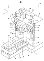
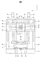
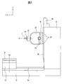
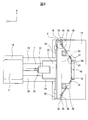
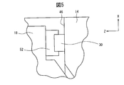
- FIG. 1 is a perspective view of a machine tool according to a preferred embodiment of the present invention. It is a front view of the machine tool of FIG. It is a side view of the machine tool of FIG. It is a top view of the machine tool of FIG. It is an enlarged view of the part shown by V in FIG.
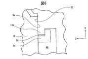
- FIG. 5 is an enlarged view of a portion indicated by VI in FIG. 4.
- a machine tool 10 constitutes a horizontal machining center, and includes a bed 12 as a base fixed to the floor of a factory, a front portion (front side) of the bed 12.
- a Y-axis slider 18 that is provided on the front surface of the column 14 so as to be movable in the vertical direction or the Y-axis direction.
- An X-axis slider 20 provided on the X-axis, and a spindle head 22 attached to the X-axis slider 20 and rotatably supporting a spindle 24.
- the column 14 has a recess 48 and a protrusion 14a that protrudes inward from the side wall of the recess 48.
- the recess 48 has a substantially trapezoidal shape in which a cross section perpendicular to the Y-axis is tapered backward from the front surface of the column 14.
- a pair of Y-axis guide rails 30 extending in the vertical direction as a first guide are attached to the front surface 46 outside the recess 48 in the X-axis direction.
- At least one guide surface 32 in the present embodiment which faces the front in the Z-axis direction and extends in the Y-axis direction, is provided as the second guide.
- the protruding portion 14a protrudes in the X-axis direction so as to form an extended portion of the guide surface 32.
- the protruding portion 14a has a front surface formed flush with the guide surface 32 and a back surface opposite to the front surface.
- the Y-axis guide rail 30 and the guide surface 32 form a guide for guiding the movement of the Y-axis slider 18 as a moving body in the vertical direction that is the gravity direction.
- the table 16 is provided so as to reciprocate along a pair of Z-axis guide rails 26 extending in the horizontal Z-axis direction (direction perpendicular to the paper surface of FIG. 2) on the upper surface of the bed 12.
- a pallet P for fixing a work (not shown) is attached to the upper surface of the table 16.
- the table 16 incorporates a B-axis servomotor (not shown), and supports the pallet P so as to be capable of rotational feed in the B-axis direction about the axis Ob extending in the vertical direction. .
- the bed 12 is a Z-axis feed device that reciprocates the table 16 along the Z-axis guide rail 26, and a ball screw 28 extending in the Z-axis direction, and a Z-axis connected to one end of the ball screw 28.
- a servo motor 29 is provided, and a nut (not shown) that engages with the ball screw 28 is attached to the table 16.
- the Y-axis slider 18 is provided so as to reciprocate along a pair of Y-axis guide rails 30 extending in the Y-axis direction (vertical direction) and a pair of guide surfaces 32 on the front surface of the column 14.
- the column 14 includes a pair of ball screws 34 extending in the Y-axis direction and a pair of balls as a Y-axis feeding device that reciprocates the Y-axis slider 18 along the Y-axis guide rail 30 and the guide surface 32.
- a Y-axis servomotor 36 connected to one end of each of the screws 34, in this example, the upper end is provided.
- a nut (not shown) that engages with the ball screw 34 is attached to the Y-axis slider 18. Yes.
- the X-axis slider 20 is provided so as to reciprocate along a pair of X-axis guide rails 38 extending in the X-axis direction (left-right direction in FIG. 2) on the front surface of the Y-axis slider 18.
- the Y-axis slider 18 is connected to a ball screw 40 extending in the X-axis direction and one end of the ball screw 40 as an X-axis feeding device that reciprocates the X-axis slider 20 along the X-axis guide rail 38.
- An X-axis servo motor 42 is provided, and a nut (not shown) that engages with the ball screw 40 is attached to the X-axis slider 20.
- the X-axis slider 20 has a pair of A-axis arms 20a protruding forward in the Z-axis direction, and the spindle head 22 is located in the A-axis direction around the tilt axis Oa parallel to the X-axis between the A-axis arms 20a. It is supported so that it can be rotated.
- One of the A-axis arms 20a incorporates an A-axis servo motor (not shown) for rotating and feeding the spindle head 22 in the A-axis direction around the tilt axis Oa.
- the spindle head 22 supports the spindle 24 so as to be rotatable around the central axis O.
- the spindle head 22 incorporates a servo motor (not shown) that rotationally drives the spindle 24.
- the machine tool 10 sends the X axis, Y axis, Z axis, A axis, and B axis according to the NC program, so that the machine tool 10 is fixed to the table 16 and fixed to the tool T mounted on the tip of the main shaft 24 and the pallet P.
- the workpiece mounted with the pallet P is relatively moved, and the workpiece is processed by the tool T.
- the vertical movement of the Y-axis slider 18 is guided by the pair of Y-axis guide rails 30 and the pair of guide surfaces 32.
- the pair of Y-axis guide rails 30 are disposed on the front surface 46 of the column 14.
- the pair of guide surfaces 32 are disposed in a recess 48 having a substantially trapezoidal cross section along a plane perpendicular to the Y axis formed on the front surface 46 of the column 14 and faces the front in the Z axis direction.
- the pair of Y-axis guide rails 30 are arranged in the column 14 forward in the Z-axis direction and outside in the X-axis direction with respect to the guide surface 32.
- the Y-axis guide rail 30 and the guide surface 32 are arranged at each vertex of a trapezoid 50 indicated by a two-dot chain line.
- the pair of ball screws 34 is disposed substantially along the hypotenuse of the trapezoid 50 at the center between the Y-axis guide rail 30 and the guide surface 32.
- the Y-axis slider 18 is attached with a pair of carriages 52 that engage with the Y-axis guide rail 30.
- the carriage 52 is a rolling type carriage provided with a plurality of rolling elements such as rollers and balls, and the Y-axis guide rail 30 forms a rolling type guide.
- the Y-axis slider 18 has a holding plate 54 that engages with the protrusion 14 a and a sliding surface 18 a that slides with respect to the guide surface 32.
- the pressing plate 54 is slidably in close contact with the back surface of the protruding portion 14 a and presses the sliding surface 18 a of the Y-axis slider 18 against the guide surface 32.
- the guide surface 32 forms a sliding type guide.
- a gap 56 is provided between the side surface of the protrusion 14 a and the presser plate 54.
- the Y-axis slider 18 is attached to the column 14 so as to be movable in the vertical direction by a second guide composed of the surface 32, the sliding surface 18a, the protruding portion 14a, and the pressing plate 54.
- the spindle head 22 since the back surface of the Y-axis slider 18 is constrained by the guide surface 32, the X-axis slider 20, the spindle head 22 has its own weight and the cutting resistance in the Y-axis direction acting on the spindle 24 around the X-axis of the Y-axis slider 18. Torsional deformation is prevented or reduced.
- the presser plate 54 is slidably in close contact with the back surface of the protruding portion 14a, whereby the sliding surface 18a of the Y-axis slider 18 is pressed against the guide surface 32, and deformation of the Y-axis slider 18 is minimized.
- the interval between the pair of second guides is narrower than the interval between the pair of first guides, the interval between the pair of first guides and the interval between the pair of second guides are equal.
- the Y-axis slider 18 becomes smaller and lighter, and the load in the gravity direction acting on the Y-axis can be reduced.
- the machine tool is a horizontal spindle with the spindle oriented horizontally, but since it has an A axis, it can also be used as a machine tool with a vertical spindle with the spindle oriented vertically. Is possible.
- the present invention is also effective in a normal vertical spindle machine tool that does not have an A-axis.
- both the first guide and the second guide may be a sliding guide composed of a guide surface and a sliding surface, or both the first guide and the second guide may be a rolling guide composed of a guide rail and a carriage.
- the first guide having a wide interval between the pair of guides as the rolling guide, the friction coefficient is reduced and the parallelism in the Y-axis direction can be easily adjusted.
- the second guide provided inside and rearward of the first guide as a sliding guide, the friction damping ability is enhanced, and the force to tilt the Y-axis slider 18 forward is applied to the guide surface 32 of the protrusion 14a. It is possible to prevent the Y-axis slider 18 from being tilted forward by receiving the entire rear surface.
Landscapes
- Engineering & Computer Science (AREA)
- Mechanical Engineering (AREA)
- Machine Tool Units (AREA)
Abstract
Priority Applications (5)
| Application Number | Priority Date | Filing Date | Title |
|---|---|---|---|
| EP13893363.5A EP3045263B1 (fr) | 2013-09-13 | 2013-09-13 | Machine-outil |
| CN201380079482.8A CN105517753B (zh) | 2013-09-13 | 2013-09-13 | 机床 |
| PCT/JP2013/074928 WO2015037155A1 (fr) | 2013-09-13 | 2013-09-13 | Machine-outil |
| JP2015536418A JP6195620B2 (ja) | 2013-09-13 | 2013-09-13 | 工作機械 |
| US15/021,644 US9878408B2 (en) | 2013-09-13 | 2013-09-13 | Machine tool |
Applications Claiming Priority (1)
| Application Number | Priority Date | Filing Date | Title |
|---|---|---|---|
| PCT/JP2013/074928 WO2015037155A1 (fr) | 2013-09-13 | 2013-09-13 | Machine-outil |
Publications (1)
| Publication Number | Publication Date |
|---|---|
| WO2015037155A1 true WO2015037155A1 (fr) | 2015-03-19 |
Family
ID=52665295
Family Applications (1)
| Application Number | Title | Priority Date | Filing Date |
|---|---|---|---|
| PCT/JP2013/074928 Ceased WO2015037155A1 (fr) | 2013-09-13 | 2013-09-13 | Machine-outil |
Country Status (5)
| Country | Link |
|---|---|
| US (1) | US9878408B2 (fr) |
| EP (1) | EP3045263B1 (fr) |
| JP (1) | JP6195620B2 (fr) |
| CN (1) | CN105517753B (fr) |
| WO (1) | WO2015037155A1 (fr) |
Cited By (3)
| Publication number | Priority date | Publication date | Assignee | Title |
|---|---|---|---|---|
| CN108067932A (zh) * | 2017-12-19 | 2018-05-25 | 珠海格力智能装备技术研究院有限公司 | 主轴平衡结构及具有其的机床 |
| JP2022540743A (ja) * | 2019-07-17 | 2022-09-20 | ライシャウァー アーゲー | 溝状の外形を有する回転部品をロール機械加工する工作機械及び方法 |
| CN116871924A (zh) * | 2023-08-09 | 2023-10-13 | 深圳市景颢智造自动化科技有限公司 | 一种背附式xy平台 |
Families Citing this family (10)
| Publication number | Priority date | Publication date | Assignee | Title |
|---|---|---|---|---|
| USD788196S1 (en) * | 2014-09-12 | 2017-05-30 | Pocket NC Company | Multi-axis machine |
| TW201700213A (zh) * | 2015-06-30 | 2017-01-01 | 國立中興大學 | 可改善熱誤差之工具機 |
| DE102017007962A1 (de) * | 2017-08-24 | 2019-02-28 | Deckel Maho Seebach Gmbh | Werkzeugmaschine |
| DE102017216446A1 (de) * | 2017-09-17 | 2019-03-21 | Deckel Maho Seebach Gmbh | Werkzeugmaschine zur Bearbeitung eines Werkstücks |
| USD861750S1 (en) * | 2018-05-02 | 2019-10-01 | Pocket NC Company | Multi-axis machine |
| CN109834335A (zh) * | 2019-02-28 | 2019-06-04 | 滁州精峰机电科技有限公司 | 一种冷柜内胆钣金成型线 |
| JPWO2021172530A1 (fr) * | 2020-02-28 | 2021-09-02 | ||
| WO2022219773A1 (fr) * | 2021-04-15 | 2022-10-20 | Dmg森精機株式会社 | Machine-outil |
| US20240189954A1 (en) * | 2021-04-15 | 2024-06-13 | Dmg Mori Co., Ltd. | Machine tool |
| CN114012447B (zh) * | 2022-01-06 | 2023-06-30 | 广东原点智能技术有限公司 | 一种多主轴钻铣设备 |
Citations (5)
| Publication number | Priority date | Publication date | Assignee | Title |
|---|---|---|---|---|
| JPH04136634U (ja) * | 1991-06-06 | 1992-12-18 | オークマ株式会社 | 横型マシニングセンタにおける主軸頭のガイド機構 |
| JPH11235631A (ja) * | 1998-02-19 | 1999-08-31 | Toyoda Mach Works Ltd | 工作機械 |
| JP2000024853A (ja) * | 1998-07-08 | 2000-01-25 | Mori Seiki Co Ltd | 工作機械 |
| JP2003326429A (ja) | 2002-05-10 | 2003-11-18 | Toshiba Mach Co Ltd | ハイブリッド案内機構を有する工作機械 |
| JP2005153121A (ja) * | 2003-11-28 | 2005-06-16 | Mitsubishi Heavy Ind Ltd | 送り系構造及びこれを備えた工作機械 |
Family Cites Families (29)
| Publication number | Priority date | Publication date | Assignee | Title |
|---|---|---|---|---|
| FR1592974A (fr) * | 1968-11-25 | 1970-05-19 | ||
| FR2425918A2 (fr) * | 1978-01-31 | 1979-12-14 | Mavilor Manuf Vilebrequins | Cadre vertical mobile support de tete d'entrainement d'outils avec moyen de guidage par rapport au bati, pour toutes machines-outils d'utilisation generale |
| US4658485A (en) * | 1984-08-21 | 1987-04-21 | Yang Tai Her | Machine tool with articulated crossbeam |
| JPS62132179A (ja) | 1985-12-04 | 1987-06-15 | Sanwa Electron Kk | Icピンの検査装置 |
| SU1574375A1 (ru) * | 1987-10-22 | 1990-06-30 | Институт автоматики и электрометрии СО АН СССР | Токарный станок |
| JPH04136634A (ja) | 1990-09-27 | 1992-05-11 | Matsushita Electric Ind Co Ltd | 湯水混合制御装置 |
| JPH0580632U (ja) * | 1992-04-06 | 1993-11-02 | 株式会社椿本チエイン | コラムと昇降フレームの撓み防止構造 |
| JPH09269005A (ja) | 1996-04-01 | 1997-10-14 | Ishikawajima Harima Heavy Ind Co Ltd | 減衰機能を備えたダンピング軸受 |
| JP3256879B2 (ja) * | 1999-07-01 | 2002-02-18 | ホーコス株式会社 | 工作機械 |
| JP3357947B2 (ja) * | 2000-10-12 | 2002-12-16 | ホーコス株式会社 | 工作機械 |
| JP4190738B2 (ja) * | 2001-02-07 | 2008-12-03 | 株式会社ジェイテクト | 工作機械における半浮上式スライド案内機構 |
| JP2003266257A (ja) * | 2002-03-14 | 2003-09-24 | Makino Milling Mach Co Ltd | 工作機械 |
| CN2602870Y (zh) * | 2003-03-17 | 2004-02-11 | 亚太精英股份有限公司 | 综合加工中心机的立柱支持结构 |
| JP4427689B2 (ja) * | 2004-07-08 | 2010-03-10 | オークマ株式会社 | 工作機械 |
| JP4672299B2 (ja) * | 2004-07-26 | 2011-04-20 | ヤマザキマザック株式会社 | 工作機械のバランサ取付角度算出方法、及び工作機械 |
| JP2006239854A (ja) * | 2005-02-04 | 2006-09-14 | Nagase Integrex Co Ltd | 工作機械 |
| JP2008155339A (ja) * | 2006-12-26 | 2008-07-10 | Mitsubishi Heavy Ind Ltd | 主軸倒れ検出装置及びこれを備えた工作機械 |
| US7264581B1 (en) * | 2007-01-08 | 2007-09-04 | Ding Koan Machinery Co., Ltd | Machining center with a relay tool exchange device |
| JP2008264891A (ja) * | 2007-04-16 | 2008-11-06 | Mori Seiki Co Ltd | ユニバーサルヘッドおよびこれを有する工作機械 |
| EP2255921B1 (fr) * | 2008-02-29 | 2012-09-19 | Horkos Corp | Machine-outil |
| US7591619B1 (en) * | 2008-04-01 | 2009-09-22 | Buffalo Machinery Co., Ltd. | Machining apparatus |
| CN101543961B (zh) * | 2009-05-12 | 2010-07-07 | 常州昌隆机床制造有限公司 | 龙门机床立柱横梁复合导轨结构 |
| JP5644082B2 (ja) | 2009-10-06 | 2014-12-24 | 株式会社ジェイテクト | 工作機械の主軸装置 |
| US8887361B2 (en) * | 2009-10-29 | 2014-11-18 | Dalian Kede Numerical Control Co., Ltd | Vertical turning-milling complex machining center |
| JP5582916B2 (ja) | 2010-08-13 | 2014-09-03 | 株式会社東京精密 | 研削盤 |
| JP5597491B2 (ja) | 2010-09-08 | 2014-10-01 | 新日本工機株式会社 | Nc工作機械 |
| TW201221277A (en) * | 2010-11-29 | 2012-06-01 | Ind Tech Res Inst | Moving beam type machine tool |
| JP2012143819A (ja) * | 2011-01-07 | 2012-08-02 | Toshiba Mach Co Ltd | 工作機械の主軸およびこの主軸を用いた工作機械 |
| CN102275087B (zh) * | 2011-08-12 | 2013-04-17 | 福建省威诺数控有限公司 | 框架式立柱四导轨运动结构的铣床的侧加工装置 |
-
2013
- 2013-09-13 CN CN201380079482.8A patent/CN105517753B/zh active Active
- 2013-09-13 EP EP13893363.5A patent/EP3045263B1/fr active Active
- 2013-09-13 JP JP2015536418A patent/JP6195620B2/ja active Active
- 2013-09-13 US US15/021,644 patent/US9878408B2/en active Active
- 2013-09-13 WO PCT/JP2013/074928 patent/WO2015037155A1/fr not_active Ceased
Patent Citations (5)
| Publication number | Priority date | Publication date | Assignee | Title |
|---|---|---|---|---|
| JPH04136634U (ja) * | 1991-06-06 | 1992-12-18 | オークマ株式会社 | 横型マシニングセンタにおける主軸頭のガイド機構 |
| JPH11235631A (ja) * | 1998-02-19 | 1999-08-31 | Toyoda Mach Works Ltd | 工作機械 |
| JP2000024853A (ja) * | 1998-07-08 | 2000-01-25 | Mori Seiki Co Ltd | 工作機械 |
| JP2003326429A (ja) | 2002-05-10 | 2003-11-18 | Toshiba Mach Co Ltd | ハイブリッド案内機構を有する工作機械 |
| JP2005153121A (ja) * | 2003-11-28 | 2005-06-16 | Mitsubishi Heavy Ind Ltd | 送り系構造及びこれを備えた工作機械 |
Non-Patent Citations (1)
| Title |
|---|
| See also references of EP3045263A4 * |
Cited By (4)
| Publication number | Priority date | Publication date | Assignee | Title |
|---|---|---|---|---|
| CN108067932A (zh) * | 2017-12-19 | 2018-05-25 | 珠海格力智能装备技术研究院有限公司 | 主轴平衡结构及具有其的机床 |
| JP2022540743A (ja) * | 2019-07-17 | 2022-09-20 | ライシャウァー アーゲー | 溝状の外形を有する回転部品をロール機械加工する工作機械及び方法 |
| JP7685442B2 (ja) | 2019-07-17 | 2025-05-29 | ライシャウァー アーゲー | 溝状の外形を有する回転部品をロール機械加工する工作機械及び方法 |
| CN116871924A (zh) * | 2023-08-09 | 2023-10-13 | 深圳市景颢智造自动化科技有限公司 | 一种背附式xy平台 |
Also Published As
| Publication number | Publication date |
|---|---|
| CN105517753A (zh) | 2016-04-20 |
| EP3045263B1 (fr) | 2021-02-17 |
| CN105517753B (zh) | 2018-04-27 |
| EP3045263A1 (fr) | 2016-07-20 |
| EP3045263A4 (fr) | 2017-05-24 |
| JPWO2015037155A1 (ja) | 2017-03-02 |
| US20160221134A1 (en) | 2016-08-04 |
| US9878408B2 (en) | 2018-01-30 |
| JP6195620B2 (ja) | 2017-09-13 |
Similar Documents
| Publication | Publication Date | Title |
|---|---|---|
| JP6195620B2 (ja) | 工作機械 | |
| JP4989766B2 (ja) | 横形工作機械 | |
| WO2011016438A1 (fr) | Dispositif de guidage de piston dune machine-outil | |
| KR20120084909A (ko) | 고강성 복합가공기 | |
| JP6389618B2 (ja) | 工作機械の移動体案内機構 | |
| JP2008279541A (ja) | 工作機械 | |
| JP5375500B2 (ja) | 工作機械 | |
| KR102165419B1 (ko) | 공작기계의 x축 이송장치 | |
| JP5147317B2 (ja) | レーザ・パンチ複合加工機 | |
| KR20110071178A (ko) | 수평방향 이송구조가 개선된 문형 공작기계 | |
| JP6779319B2 (ja) | 工作機械 | |
| JP5435169B1 (ja) | 工作機械 | |
| JP4996327B2 (ja) | 工作機械 | |
| CN102248431B (zh) | 机床的进给装置 | |
| JP4431788B2 (ja) | 工作機械 | |
| RU168927U1 (ru) | Вертикальный фрезерно-сверлильно-расточной станок с чпу | |
| CN202607252U (zh) | 工作台移动式龙门铣床上的丝杠支撑装置 | |
| JP5436801B2 (ja) | 加工機におけるマルチ加工ユニット | |
| JP2017148872A (ja) | ワークレスト構造、ワークレスト及び心なし研削盤 | |
| JP4449583B2 (ja) | マシニングセンタおよびマシニングセンタのコラム支持方法 | |
| KR101953582B1 (ko) | 유압 치공구의 얼라인먼트가 개선된 머시닝 센터 | |
| JP5721506B2 (ja) | 工作機械 | |
| CN101862840A (zh) | 一种机床拖板滑动结构 | |
| JP6729256B2 (ja) | 工作機械 | |
| JP6745725B2 (ja) | 工作機械 |
Legal Events
| Date | Code | Title | Description |
|---|---|---|---|
| 121 | Ep: the epo has been informed by wipo that ep was designated in this application |
Ref document number: 13893363 Country of ref document: EP Kind code of ref document: A1 |
|
| ENP | Entry into the national phase |
Ref document number: 2015536418 Country of ref document: JP Kind code of ref document: A |
|
| WWE | Wipo information: entry into national phase |
Ref document number: 15021644 Country of ref document: US |
|
| NENP | Non-entry into the national phase |
Ref country code: DE |
|
| REEP | Request for entry into the european phase |
Ref document number: 2013893363 Country of ref document: EP |
|
| WWE | Wipo information: entry into national phase |
Ref document number: 2013893363 Country of ref document: EP |