WO2015037298A1 - サービスホールカバー及び車両用ユニット搭載構造 - Google Patents
サービスホールカバー及び車両用ユニット搭載構造 Download PDFInfo
- Publication number
- WO2015037298A1 WO2015037298A1 PCT/JP2014/066209 JP2014066209W WO2015037298A1 WO 2015037298 A1 WO2015037298 A1 WO 2015037298A1 JP 2014066209 W JP2014066209 W JP 2014066209W WO 2015037298 A1 WO2015037298 A1 WO 2015037298A1
- Authority
- WO
- WIPO (PCT)
- Prior art keywords
- service hole
- vehicle
- service
- cover
- hole cover
- Prior art date
- Legal status (The legal status is an assumption and is not a legal conclusion. Google has not performed a legal analysis and makes no representation as to the accuracy of the status listed.)
- Ceased
Links
Images




Classifications
-
- B—PERFORMING OPERATIONS; TRANSPORTING
- B60—VEHICLES IN GENERAL
- B60K—ARRANGEMENT OR MOUNTING OF PROPULSION UNITS OR OF TRANSMISSIONS IN VEHICLES; ARRANGEMENT OR MOUNTING OF PLURAL DIVERSE PRIME-MOVERS IN VEHICLES; AUXILIARY DRIVES FOR VEHICLES; INSTRUMENTATION OR DASHBOARDS FOR VEHICLES; ARRANGEMENTS IN CONNECTION WITH COOLING, AIR INTAKE, GAS EXHAUST OR FUEL SUPPLY OF PROPULSION UNITS IN VEHICLES
- B60K1/00—Arrangement or mounting of electrical propulsion units
- B60K1/04—Arrangement or mounting of electrical propulsion units of the electric storage means for propulsion
-
- B—PERFORMING OPERATIONS; TRANSPORTING
- B62—LAND VEHICLES FOR TRAVELLING OTHERWISE THAN ON RAILS
- B62D—MOTOR VEHICLES; TRAILERS
- B62D25/00—Superstructure or monocoque structure sub-units; Parts or details thereof not otherwise provided for
- B62D25/20—Floors or bottom sub-units
-
- B—PERFORMING OPERATIONS; TRANSPORTING
- B62—LAND VEHICLES FOR TRAVELLING OTHERWISE THAN ON RAILS
- B62D—MOTOR VEHICLES; TRAILERS
- B62D25/00—Superstructure or monocoque structure sub-units; Parts or details thereof not otherwise provided for
- B62D25/24—Superstructure sub-units with access or drainage openings having movable or removable closures; Sealing means therefor
Definitions
- the present invention relates to a service hole cover and a vehicle unit mounting structure.
- Japanese Unexamined Patent Application Publication No. 2009-083601 discloses an electric vehicle in which a battery unit having a service plug is mounted under a floor panel.
- the service plug is configured to be able to electrically cut off the electric circuit of the battery module by manually operating the service plug.
- a boot mounting hole for operating the service plug is formed, and a cap member that closes the boot mounting hole is mounted by a bolt. And in the center part of this cap member, the incorrect assembly
- the misassembly prevention convex portion at the center of the cap member contributes to improving the strength of the cap member, but the upper surface of the cap member is recessed by forming the misassembly prevention convex portion. And by storing water for a long time in this dent, a cap member deteriorates and it becomes easy to break. Therefore, there was room for improvement in this respect.
- JP2013-107542A and JP2013-112225A Note that related techniques are disclosed in JP2013-107542A and JP2013-112225A.
- the present invention is intended to improve the strength of the service hole cover while ensuring the drainage performance of the upper surface of the service hole cover in consideration of the above facts.
- the service hole cover according to the first aspect includes a box-shaped cover body that is detachably provided on the panel so as to cover the service hole formed on the vehicle panel, and includes an upper portion of the cover body. And a ceiling portion formed with a groove-like recess having a convex shape on the panel side and an end portion being released on the upper surface.
- the ceiling portion of the cover body of the service hole cover is convex on the panel side and has a groove-shaped recess on the upper surface. Therefore, when a load is input to the ceiling from above, the ceiling is deformed so that a compressive force is applied. Also, when a load is input to the ceiling from below, the ceiling is deformed so that a compressive force is applied. In this way, when the ceiling portion is compressively deformed, for example, compared to a case where the ceiling portion is tensilely deformed, breakage such as a crack or a crack is less likely to occur, and the strength is improved.
- the concave portion on the top surface of the ceiling portion has a groove shape with the end portions released, even if water enters the concave portion, water is drained from both ends of the concave portion. Therefore, deterioration due to water being stored in the concave portion of the ceiling for a long period is suppressed or prevented.
- the groove-shaped recess formed in the ceiling has two functions, namely a function of improving strength and a function of draining. Therefore, the strength of the service hole cover is improved while ensuring the drainage performance of the upper surface of the service hole cover.
- the bottom portion of the recess is inclined downward from the central portion in the groove direction toward both ends, or from one end in the groove direction to the other end. It is inclined downward as it goes to the section.
- the bottom of the recess is inclined downward from the center in the groove direction toward both ends, or inclined downward from one end in the groove direction toward the other end. Yes. Therefore, the water that has entered the recess flows along the slope and is drained from both ends or the other end, so that drainage performance is improved.
- a first rib extending along the side wall height direction is formed on the outer surface of the side wall of the cover body.
- deformation of the side wall is suppressed by the first rib extending along the side wall height direction formed on the outer surface of the side wall of the cover body, and the strength of the service hole cover is further improved.
- the first rib is formed on the outer surface of the side wall of the service hole cover, when the member is disposed on the upper surface of the service hole cover, the member can be disposed close to the upper surface. .
- the vehicle unit mounting structure is provided on a vehicle floor in which a service hole is formed, and a vehicle unit disposed on the vehicle floor in the vehicle vertical direction, and protrudes toward the service hole.
- the groove-shaped recess formed in the ceiling portion of the cover body of the service hole cover has two functions of a strength improving function and a draining function. Therefore, the strength of the service hole cover is improved while ensuring the drainage performance of the upper surface of the service hole cover.
- the strength of the service hole cover is improved.
- the duct arranged on the upper side of the service hole cover in the vehicle vertical direction can be brought close to the upper surface of the service hole cover.
- a buffer member is sandwiched between the ceiling of the service hall and the duct. Therefore, since the ceiling portion of the service hole cover and the duct come into contact with each other through the buffer member due to vibration or the like during traveling, the shock is buffered and the service hole cover and the duct are prevented from being damaged.
- the service hole cover according to the fifth aspect is the structure according to any one of the first aspect to the third aspect, wherein the upper surface of the ceiling portion of the cover body has a crossing direction intersecting the groove direction of the recess.
- the 2nd rib extended along is formed,
- channel direction is formed in the site
- the deformation of the ceiling portion is suppressed by the second rib extending along the intersecting direction intersecting the groove direction of the recess formed on the upper surface of the ceiling portion of the cover body, and the service hole The strength of the cover is further improved.
- the second rib is formed such that the upper end portion does not exceed the upper end portion of the upper surface of the ceiling portion.
- the upper end portion of the second rib does not exceed the upper end portion of the upper surface of the ceiling portion. Therefore, when the member is disposed on the upper surface of the service hole cover, the member is brought close to the upper surface. It is possible to arrange.
- the service hole cover according to the seventh aspect is the structure according to any one of the first aspect to the third aspect, the fifth aspect, and the sixth aspect, and the inner surface of the side wall of the cover body is along the side wall height direction.
- a third rib extending is formed.
- deformation of the side wall is suppressed by the third rib extending along the side wall height direction formed on the inner surface of the side wall of the cover body, and the strength of the service hole cover is further improved.
- the member when a member is arranged on the upper side of the upper surface of the service hole cover, the member can be arranged close to the upper surface.
- the service hole cover according to the eighth aspect is the structure according to any one of the first aspect to the third aspect and the fifth aspect to the seventh aspect, wherein the groove of the recess is formed on the lower surface of the ceiling portion of the cover body.
- a fourth rib extending along the intersecting direction intersecting the direction is formed.
- the deformation of the ceiling part is suppressed by the fourth rib extending along the intersecting direction intersecting the groove direction of the recess formed in the lower surface of the ceiling part of the cover body.
- the strength of the cover is further improved.
- the member when a member is arranged on the upper side of the upper surface of the service hole cover, the member can be arranged close to the upper surface.
- the vehicle unit mounting structure according to the ninth aspect is provided on a vehicle floor in which a service hole is formed and a vehicle unit disposed on the vehicle floor in the vehicle vertical direction and projects toward the service hole.
- the service hole cover has a downward convexity formed on the ceiling of the cover body, and a groove-shaped concave portion on the upper surface has two functions, a strength improvement function and a drainage function. is doing. Therefore, the strength of the service hole cover is improved while ensuring the drainage performance of the upper surface of the service hole cover.
- the strength of the service hole cover can be improved while ensuring the drainage performance of the upper surface of the service hole cover.
- the drainage performance can be further improved.
- the strength of the service hole cover can be further improved.
- the damage to the service hole cover and the deterioration of the service hole cover can be prevented or suppressed, and the duct arranged on the upper side in the vehicle vertical direction of the service hole cover is connected to the upper surface of the service hole cover. Can be placed close to.
- the strength of the service hole cover can be further improved.
- the member can be disposed close to the upper surface of the service hole cover.
- the strength of the service hole cover can be further improved.
- the strength of the service hole cover can be further improved.
- the ninth aspect it is possible to prevent or suppress damage due to impact on the service hole cover and deterioration of the service hole cover.
- an arrow FR appropriately shown in each drawing indicates a front side in the vehicle front-rear direction (vehicle front), an arrow UP indicates an upper side in the vehicle vertical direction, and an arrow OUT indicates an outer side in the vehicle width direction.
- a vehicle 12 to which the vehicle unit mounting structure 10 according to the present embodiment is applied includes, for example, an electric vehicle, a gasoline hybrid vehicle, and the like that run using an electric motor (motor) (not shown) as a drive source.
- a battery unit 20 (see FIG. 2), which is an example of a vehicle unit that stores electric power to be supplied to an electric motor, is mounted on a lower side of a vehicle in a vertical direction of a floor panel 14 that is a fuel cell hybrid vehicle. Has been.
- the battery unit 20 of this embodiment is a fuel cell that generates electric power by an electrochemical reaction.
- the floor panel 14 is provided with a convex portion 16.
- the convex portion 16 protrudes upward in the vehicle vertical direction with respect to the general portion (reference surface) of the floor panel 14, and a service hole 18 is formed in the top wall portion 16A.
- the service hole 18 is closed from the upper side in the vehicle vertical direction by a resin service plug cover 50 as an example of a service hole cover described later.
- a battery unit 20 is disposed below the floor panel 14 in the vehicle vertical direction.
- the battery unit 20 includes a battery module 22, a battery case 24 that houses the battery module 22, and an electric circuit breaker 26 provided on the upper part of the battery case 24, and the battery case 24 includes a connecting member that is not shown in the figure. It is attached to the skeleton member which constitutes the skeleton of the vehicle lower part via.
- the battery module 22 is accommodated in the battery case 24.
- FIGS. 2 and 3 the battery module 22, the battery case 24, and the electric circuit breaker 26 are schematically illustrated.
- the electric circuit breaker 26 has a service plug 28 as an example of an operation unit.
- the service plug 28 is connected to the service hole 18. Projecting upward from The service plug 28 is covered from the upper side in the vehicle vertical direction by the service plug cover 50 that closes the service hole 18 described above.
- the resin service plug cover 50 has a box-shaped cover main body 52 that bulges upward in the vehicle vertical direction (on the opposite side to the floor panel 14) and opens downward.
- the cover main body 52 has a substantially rectangular shape with the longitudinal direction in the vehicle front-rear direction when seen in a plan view.
- flanges 56A and 56B are formed on the front side wall 54A and the rear side wall 54B in the vehicle front-rear direction of the cover main body 52 so as to extend from the lower end portion in the vehicle front-rear direction, respectively.
- the flanges 56A and 56B are fastened by screwing bolts 98 into screw holes 96 formed in the outer peripheral portion of the service hole 18 in the floor panel 14 so that the service plug cover 50 is attached to the floor panel 14. It is fixed.
- a crank-shaped bracket (not shown) fixed to the floor panel 14.
- a seal member may be interposed between the cover body 52, the lower end, and the floor panel 14.
- the ceiling 60 constituting the upper part of the cover body 52 of the service plug cover 50 is on the vehicle vertical direction lower side (the floor panel 14 side (FIGS. 1 and 2)). It is convex and a groove-like recess 62 is formed on the upper surface 60A.
- the groove-like recess 62 is formed with the ends 62A and 62B being released and the vehicle front-rear direction being the groove direction.
- the cross-sectional shape orthogonal to the groove direction (vehicle front-rear direction) of the concave portion 62 is a circular arc convex downward.
- the bottom 64 (see FIG. 2) of the recess 62 is inclined downwardly from the central portion 64 ⁇ / b> C toward the end portions 64 ⁇ / b> A and 64 ⁇ / b> B in the vehicle longitudinal direction (also FIGS. 1 and 4). reference).
- the cross-sectional shape along the vehicle front-rear direction of the bottom portion 64 of the recess 62 is a mountain shape in which the central portion 64C in the groove direction swells upward.
- the center (middle) of the recess 62 in the groove direction is the top of the mountain, but the mountain top is the vehicle front-rear direction front side and the vehicle front-rear direction rear side of the center (middle).
- the shape may be located on the side.
- the outer surface 58 ⁇ / b> A of the side wall 58 on both outer sides in the vehicle width direction of the cover body 52 of the service plug cover 50 extends along the vehicle vertical direction (the height direction of the side wall 58).
- a rib 70 extending in the direction is formed.
- a plurality of ribs 70 are formed on the outer surface 58A of the side wall 58 at intervals in the vehicle front-rear direction.
- the upper end portion (uppermost portion) 70A of the rib 70 is formed so as not to exceed the upper end portion (uppermost portion) 60C of the upper surface 60A of the ceiling portion 60 of the cover body 52. Yes.
- a duct 100 extending along the vehicle front-rear direction is disposed on the upper side of the service plug cover 50 in the vehicle vertical direction. Air conditioned by an air conditioner (not shown) flows through the duct 100. Note that the air-conditioned air flowing through the duct 100 is blown toward an occupant seated in a rear seat (not shown).
- the upper surface 60A of the ceiling portion 60 of the cover main body 52 of the service plug cover 50 and the lower surface 102 of the duct 100 are arranged close to each other.
- a sponge 110 as an example of a buffer member is provided on the lower surface 102 of the duct 100. Therefore, the sponge 110 is sandwiched between the upper surface 60A of the ceiling portion 60 of the cover main body 52 of the service plug cover 50 and the lower surface 102 of the duct 100 in a state of being elastically deformed in the vehicle vertical direction.
- the upper side of the service plug cover 50 (duct 100) in the vehicle vertical direction is covered with a console (not shown).
- the fastening of the bolt 98 is released, the service plug cover 50 is removed, and the service plug 28 of the electric circuit breaker 26 of the battery unit 20 is exposed (see FIG. 1).
- the service plug 28 exposed from the vehicle interior side is operated, the electric circuit of the battery module 22 housed in the battery case 24 is electrically cut off, and maintenance work for the battery unit 20 and the like is performed.
- the service plug 28 of the electric circuit breaker 26 of the battery unit 20 is operated from the vehicle interior side and energized. Then, the service plug cover 50 is fastened to the floor panel 14 with bolts 98.
- the service plug 28 may hit the lower surface 60B of the ceiling portion 60 due to vibration or impact during traveling of the vehicle, and a load may be input to the ceiling portion 60 from below (see F2 in FIGS. 6A and 6B).
- FIGS. 6A, 6B, and 6C showing the service plug cover 50 of the present embodiment, and FIGS. 10A, 10B, and 10C showing the service plug cover 950 of the comparative example are used. Will be described.
- the imaginary line (two-dot broken line) of a figure has shown the state which the ceiling part deform
- the ceiling portion 60 of the resin service plug cover 50 of the present embodiment is convex downward in the vehicle vertical direction (floor panel 14 side).
- a groove-like recess 62 is formed on the upper surface 60A (see also FIGS. 1 to 4).
- the ceiling portion 60 of the resin service plug cover 50 of the present embodiment is convex on the vehicle vertical direction lower side (floor panel 14 side) and has a groove-like recess 62 formed on the upper surface 60A.
- the strength of the service plug cover 50 is improved as compared with the case where is flat.
- the recess 62 on the upper surface 60A of the ceiling 60 has a groove shape, and the end portions 62A and 62B in the groove direction (vehicle front-rear direction) are open. Therefore, even if water enters the recess 62 of the ceiling portion 60, the water is drained from the end portions 64A and 64B.
- the bottom 64 of the recess 62 is inclined downwardly from the center 64C toward the ends 64A and 64B in the vehicle front-rear direction.
- the cross-sectional shape along the vehicle front-rear direction of the bottom portion 64 of the concave portion 62 is a mountain shape in which the central portion 64C bulges upward (see FIG. 3). Therefore, the water that has entered the recess 62 flows along the slope and is drained from the end portions 64A and 64B. Therefore, deterioration due to water being stored in the concave portion 62 of the ceiling portion 60 for a long period is suppressed or prevented. Moreover, the strength reduction accompanying the deterioration of the ceiling part 60 is suppressed or prevented.
- the groove-like recess 62 of the upper surface 60A formed by the ceiling 60 projecting downward in the vehicle vertical direction (floor panel 14 side) has a function of improving the strength of the service plug cover 50 and drainage. And two functions. Therefore, the strength of the service plug cover 50 is improved while the drainage performance of the upper surface 60A of the ceiling portion 60 of the service plug cover 50 is ensured.
- the rib 70 is formed on the outer surface 58A of the side wall 58 of the service plug cover 50, the deformation of the side wall 58 when the load F1 and the load F2 are applied is suppressed, and the service plug cover 50 The strength is further improved.
- the rib 70 is formed on the outer surface 58A of the side wall 58 of the service plug cover 50, and the upper end portion (uppermost portion) 70A of the rib 70 is the upper end portion (uppermost portion) 60C of the upper surface 60A of the ceiling portion 60 of the cover body 52. Is not exceeded. Therefore, the lower surface 102 of the duct 100 can be disposed close to the upper surface 60A of the ceiling portion 60 of the service plug cover 50 (see FIG. 5).
- a sponge 110 is sandwiched between the upper surface 60A of the ceiling portion 60 of the service plug cover 50 and the lower surface 102 of the duct 100.
- the upper surface 60A of the ceiling portion 60 of the service plug cover 50 and the lower surface 102 of the duct 100 abut against each other through the sponge 110 due to vibration during traveling, etc., so that the shock is buffered and the service plug cover 50 and the duct 100 are damaged. Is prevented.
- the rib 70 is formed on the outer surface 58A of the side wall 58 of the service plug cover 50, but is not limited thereto.
- ribs 72 extending along the intersecting direction intersecting the groove direction of the recess 62 are formed on the upper surface 60 ⁇ / b> A of the ceiling 60.
- a rib 74 extending along the crossing direction intersecting the groove direction of the recess 62 is formed on the lower surface 60B of the portion 60, and extends along the vehicle vertical direction (the height direction of the side wall 58) on the inner surface 58B of the side wall 58.
- An existing rib 76 may be formed.
- the crossing direction mentioned above is an orthogonal direction orthogonal to the groove direction of the recessed part 62 in this modification, and is a vehicle width direction.
- ribs 72, 74, 76 are formed at intervals in the groove direction (vehicle longitudinal direction).
- the rib 72 formed on the upper surface 60 ⁇ / b> A of the ceiling portion 60 has a notch 73 as an example of a drainage portion at a portion corresponding to the bottom 64 of the recess 62. Further, the position in the vehicle vertical direction of the substantially horizontal upper end portion 72 ⁇ / b> A of the rib 72 is formed so as not to exceed the upper end portion 60 ⁇ / b> C of the ceiling portion 60.
- the rib 72 is formed on the upper surface 60A of the ceiling portion 60, and the rib 74 is formed on the lower surface 60B of the ceiling portion 60.
- a rib 76 is formed on 58B. Therefore, the deformation of the ceiling portion 60 and the side wall 58 is suppressed, and the strength of the service plug cover 51 is improved as compared with the service plug cover 50.
- the notch 73 is formed in the rib 72 of the upper surface 60 ⁇ / b> A of the ceiling part 60, even if water enters between the rib 72 and the rib 72, it flows from the notch 73, and finally the recess 62. The water is drained from the end portions 64A and 64B. Therefore, even if the rib 72 is formed on the upper surface 60 ⁇ / b> A of the ceiling 60 so as to intersect the recess 62, deterioration due to water stored in the recess 62 for a long period of time is suppressed or prevented.
- the drainage may be performed by a through hole penetrating in the groove direction.
- the position of the upper end portion 72A of the rib 72 in the vehicle vertical direction is formed so as not to exceed the upper end portion 60C of the ceiling portion 60. Therefore, the upper surface 60A of the ceiling portion 60 of the service plug cover 50 and the lower surface 102 of the duct 100 can be disposed close to each other.
- the height of the rib 72 of the upper surface 60A of the ceiling 60 is increased, that is, the ceiling 60
- the rib 72 may be formed so as to exceed the upper end portion 60C, and the strength may be further improved.
- any one or more of four ribs including a rib 70 on the outer surface 58A of the side wall 58, a rib 72 on the upper surface 60A of the ceiling 60, a rib 74 on the lower surface 60B of the ceiling 60, and a rib 76 on the inner surface 58B of the side wall 58.
- the structure in which is formed may be used. Or the structure in which these ribs are not formed may be sufficient.
- the entire ceiling portion 60 is convex downward, so that the central portion of the upper surface 60A in the vehicle width direction is recessed and one groove-shaped recess 62 is formed, but the present invention is not limited to this.
- a part of the ceiling portion 60 (a portion on the outer side in the vehicle width direction (a portion shifted outward from the center)) is convex downward.
- a groove-shaped recess 92 may be formed on the outer side of the upper surface 60A in the vehicle width direction.
- two groove-like recesses 92 may be formed side by side. Although illustration is omitted, three or more recesses 92 may be formed side by side.
- the bottom part 94 may incline below as it goes to both ends from the center part of a groove direction like the recessed part 62 of the said embodiment, and drainage performance may be improved (FIG. 3). reference).
- the service plug cover 51 of the second modification shown in FIGS. As described above, one or more of the rib 70 on the outer surface 58A of the side wall 58, the rib 76 on the inner surface 58B of the side wall 58, the rib 72 on the upper surface 60A of the ceiling 60, and the rib 74 on the lower surface 60B of the ceiling 60 are formed. Also good.
- the rib 72 on the upper surface 60A of the ceiling 60 has a notch 73 formed at a portion corresponding to the bottom 94 of the recess 92 to ensure drainage performance.
- the sponge 110 is sandwiched between the upper surface 60A of the ceiling portion 60 of the service plug cover 50 and the lower surface 102 of the duct 100, but the present invention is not limited to this.
- Any member having a buffer function (shock absorbing function) for preventing the service plug cover 50 and the duct 100 from being damaged may be used.
- it may be an elastic member such as rubber, or may be felt, polystyrene foam or the like.
- the groove-like recesses 62 and 92 are formed on the upper surface 60A of the ceiling portion 60 along the vehicle front-rear direction, but the present invention is not limited to this.
- a groove-shaped recess may be formed along the vehicle width direction, or a groove-shaped recess may be formed obliquely with an angle with respect to the vehicle front-rear direction.
- the recessed part along the vehicle front-back direction and the recessed part along the vehicle width direction may be formed in the ceiling part so as to intersect.
- the bottom parts 64 and 94 of the groove-shaped recessed parts 62 and 92 inclined downward as it went to both ends from the center part of a groove direction
- drainage performance was improved.
- the drainage performance may be improved by inclining the bottoms 64 and 94 of the recesses 62 and 92 downward from one end in the groove direction toward the other end. In this case, it is only necessary that at least the other end of the recess is released.
- the bottoms 64 and 94 of the recesses 62 and 92 may be formed substantially horizontally.
- the bottom parts 64 and 94 of the recessed parts 62 and 92 are substantially horizontal, it drains from an edge part at the time of the vibration at the time of driving
- the service plug cover 50 is screwed into the screw hole 96 formed in the outer peripheral portion of the service hole 18 in the floor panel 14 and fastened, thereby fastening the service plug cover 50.
- the present invention is not limited to this.
- a weld nut may be provided on the outer periphery of the service hole 18 in the floor panel 14 and fastened with a bolt.
- a stud bolt may be provided on the outer periphery of the service hole 18 in the floor panel 14 and fastened with a nut.
- the service plug cover may be detachably provided on the floor panel (vehicle floor).
- a service plug cover (service hole cover) is a service plug (operation part) of the battery unit (vehicle battery) arrange
- the present invention is not limited to this.
- a service hole cover that covers a service hole formed to operate an operation unit other than the service plug may be used. Furthermore, the present invention can also be applied to a service hole cover that covers a service hole formed in a vehicle panel for performing various operations.
Landscapes
- Engineering & Computer Science (AREA)
- Chemical & Material Sciences (AREA)
- Combustion & Propulsion (AREA)
- Transportation (AREA)
- Mechanical Engineering (AREA)
- Body Structure For Vehicles (AREA)
- Arrangement Or Mounting Of Propulsion Units For Vehicles (AREA)
Abstract
樹脂製のサービスプラグカバー(50)の天井部(60)が車両上下方向下側(フロアパネル(14)側)に凸となり上面(60A)に溝状の凹部(62)が形成されている。また、天井部(60)の上面(60A)の凹部(62)は、溝状であり、溝方向(車両前後方向)の両端部は開放されている。
Description
本発明は、サービスホールカバー及び車両用ユニット搭載構造に関する。
特開2009-083601号公報には、フロアパネルの下にサービスプラグを有するバッテリユニットが搭載された電気自動車が開示されている。サービスプラグは、手動で操作することにより、バッテリモジュールの電気回路を電気的に遮断することができるように構成されている。また、サービスプラグを操作するためのブーツ取付孔が形成されると共に、このブーツ取付孔を塞ぐキャップ部材がボルトにより取り付けられている。そして、このキャップ部材の中央部には、下に凸の形状の誤組付防止凸部が形成されている。
このキャップ部材の中央部の誤組付防止凸部は、キャップ部材の強度向上に寄与するが、誤組付防止凸部を形成することでキャップ部材の上面が凹んでいる。そして、この凹みに水が長期間に亘って貯留されることにより、キャップ部材が劣化し破損しやすくなる。よって、この点において、改善の余地があった。
なお、関連する技術が、特開2013-107542号公報、及び特開2013-112225号公報に開示されている。
本発明は、上記事実を考慮し、サービスホールカバーの上面の排水性能を確保しつつ、サービスホールカバーの強度を向上させることが目的である。
第一態様のサービスホールカバーは、車両のパネルに形成されたサービスホールを覆うように、前記パネルに着脱可能に設けられ、下方側が開口した箱形状のカバー本体と、前記カバー本体の上部を構成し、前記パネル側に凸となり上面に端部が解放された溝状の凹部が形成された天井部と、を備える。
第一態様のサービスホールカバーでは、サービスホールカバーのカバー本体の天井部には、パネル側に凸となり上面に溝状の凹部が形成されている。よって、天井部に上方から荷重が入力された場合に天井部は圧縮力が加わるように変形する。また、天井部に下方から荷重が入力された場合にも天井部は圧縮力が加わるように変形する。このように天井部が圧縮変形する場合は、例えば天井部が引張変形する場合と比較し、割れや亀裂等の破損が発生しにくく、強度が向上する。
また、天井部の上面の凹部は端部が解放された溝状であるので、天井部に凹部に水が侵入しても、凹部の両端部から排水される。よって、天井部の凹部に水が長期間に亘って貯留されることによる劣化が抑制又は防止される。
このように、天井部に形成された溝状の凹部は、強度向上の機能と排水機能との二つの機能を有している。よって、サービスホールカバーの上面の排水性能が確保されつつ、サービスホールカバーの強度が向上する。
第二態様のサービスホールカバーは、第一態様の構成において、前記凹部の底部は、溝方向の中央部から両端部に向かうに従って下方に傾斜され、又は溝方向の一方の端部から他方の端部に向かうに従って下方に傾斜されている。
第二態様のサービスホールカバーでは、凹部の底部が、溝方向の中央部から両端部に向かうに従って下方に傾斜、又は溝方向の一方の端部から他方の端部に向かうに従って下方に傾斜されている。よって、凹部に侵入した水が傾斜に沿って流れ、両端部又は他方の端部から排水されるので、排水性能が向上する。
第三態様のサービスホールカバーは、第一態様又は第二態様の構成において、前記カバー本体の側壁の外面には、側壁高さ方向に沿って延在する第一リブが形成されている。
第三態様のサービスホールカバーでは、カバー本体の側壁の外面に形成された側壁高さ方向に沿って延在する第一リブによって、側壁の変形が抑制され、サービスホールカバーの強度が更に向上する。
また、第一リブは、サービスホールカバーの側壁の外面に形成されているので、サービスホールカバーの上面の上側に部材を配置する場合には、部材を上面に近づけて配置することが可能である。
第四態様の車両用ユニット搭載構造は、サービスホールが形成された車両フロアと、前記車両フロアの車両上下方向の下側に配置された車両用ユニットに設けられ、前記サービスホールに向けて突出する操作部と、前記車両フロアの上面に着脱可能に設けられた第一態様~第三態様のいずれか一つの態様のサービスホールカバーと、前記サービスホールカバーの車両上下方向上側に配置されたダクトと、前記ダクトと前記サービスホールカバーとの間に挟まれた弾性部材と、を備える。
第四態様の車両用ユニット搭載構造では、サービスホールカバーのカバー本体の天井部に形成された溝状の凹部は、強度向上の機能と排水機能との二つの機能を有している。よって、サービスホールカバーの上面の排水性能が確保されつつ、サービスホールカバーの強度が向上する。
よって、例えば、サービスホールカバーの天井部の上面への工具類の落下による衝撃や天井部の下面への振動による操作部の衝突による衝撃等によるサービスホールカバーの破損が防止又は抑制されると共に、凹部に水が長期間に亘って貯留されることによるサービスホールカバーの劣化が防止又は抑制される。
また、カバー本体の側壁の外面に第一リブが形成されている場合は、サービスホールカバーの強度が向上する。また、サービスホールカバーの車両上下方向上側に配置されたダクトをサービスホールカバーの上面に近づけられる。
また、サービスホールの天井部とダクトとの間には緩衝部材が挟まれている。よって、走行中の振動等によりサービスホールカバーの天井部とダクトとが緩衝部材を介して当たるので衝撃が緩衝され、サービスホールカバー及びダクトの破損が防止される。
第五態様のサービスホールカバーは、第一態様~第三態様のいずれか一つの態様の構成において、前記カバー本体の前記天井部の前記上面には、前記凹部の溝方向と交差する交差方向に沿って延在する第二リブが形成され、前記第二リブの前記凹部に形成された部位には、溝方向に貫通する排水部が形成されている。
第五態様のサービスホールカバーでは、カバー本体の天井部の上面に形成された凹部の溝方向と交差する交差方向に沿って延在する第二リブによって、天井部の変形が抑制され、サービスホールカバーの強度が更に向上する。
また、第二リブの排水部から水が流れ排水されるので、天井部の上面に第二リブを形成しても、排水性能が確保される。
第六態様のサービスホールカバーは、第五態様の構成において、前記第二リブは、上端部が前記天井部の前記上面の上端部を越えないように形成されている。
第六態様のサービスホールカバーでは、第二リブの上端部が天井部の上面の上端部を越えないので、サービスホールカバーの上面の上側に部材を配置する場合には、部材を上面に近づけて配置することが可能である。
第七態様のサービスホールカバーは、第一態様~第三態様、第五態様、第六態様のいずれか一つの態様の構成において、前記カバー本体の側壁の内面には、側壁高さ方向に沿って延在する第三リブが形成されている。
第七態様のサービスホールカバーでは、カバー本体の側壁の内面に形成された側壁高さ方向に沿って延在する第三リブによって、側壁の変形が抑制され、サービスホールカバーの強度が更に向上する。
また、サービスホールカバーの上面の上側に部材を配置する場合には、部材を上面に近づけて配置することが可能である。
第八態様のサービスホールカバーは、第一態様~第三態様、第五態様~第七態様のいずれか一つの態様の構成において、前記カバー本体の前記天井部の下面には、前記凹部の溝方向と交差する交差方向に沿って延在する第四リブが形成されている。
第八態様のサービスホールカバーでは、カバー本体の天井部の下面に形成された凹部の溝方向と交差する交差方向に沿って延在する第四リブによって、天井部の変形が抑制され、サービスホールカバーの強度が更に向上する。
また、サービスホールカバーの上面の上側に部材を配置する場合には、部材を上面に近づけて配置することが可能である。
第九態様の車両用ユニット搭載構造は、サービスホールが形成された車両フロアと、前記車両フロアの車両上下方向の下側に配置された車両用ユニットに設けられ、前記サービスホールへ向けて突出する操作部と、前記車両フロアの上面に着脱可能に設けられた第一態様~第三態様、第五態様~第八態様のいずれか一つの態様のサービスホールカバーと、を備える。
第九態様の車両用ユニット搭載構造では、サービスホールカバーのカバー本体の天井部に形成された下方に凸となり上面に溝状の凹部は、強度向上の機能と排水機能との二つの機能を有している。よって、サービスホールカバーの上面の排水性能が確保されつつ、サービスホールカバーの強度が向上する。
したがって、例えば、サービスホールカバーの天井部の上面への工具類の落下による衝撃や振動による操作部の天井部の下面への衝突による衝撃等によるサービスホールカバーの破損が防止又は抑制されると共に、凹部に水が長期間に亘って貯留されることによるサービスホールカバーの劣化が防止又は抑制される。
第一態様によれば、サービスホールカバーの上面の排水性能を確保しつつ、サービスホールカバーの強度を向上させることができる。
第二態様によれば、排水性能を更に向上させることができる。
第三態様によれば、サービスホールカバーの強度を更に向上させることができる。
第四態様によれば、サービスホールカバーへの衝撃による破損及びサービスホールカバーの劣化を防止又は抑制することができると共に、サービスホールカバーの車両上下方向上側に配置されたダクトをサービスホールカバーの上面に近づけた配置することができる。
第五態様によれば、サービスホールカバーの強度を更に向上させることができる。
第六態様によれば、サービスホールカバー上面に部材を近づけて配置することができる。
第七態様によれば、サービスホールカバーの強度を更に向上させることができる。
第八態様によれば、サービスホールカバーの強度を更に向上させることができる。
第九態様によれば、サービスホールカバーへの衝撃による破損及びサービスホールカバーの劣化を防止又は抑制することができる。
以下、図面を参照しながら、本発明の一実施形態に係るサービスプラグカバー及び車両用ユニット搭載構造について説明する。なお、各図において適宜示される矢印FRは車両前後方向の前側(車両前方)を示し、矢印UPは車両上下方向の上側を示し、矢印OUTは車両幅方向の外側を示している。
図1~図3に示すように、本実施形態に係る車両用ユニット搭載構造10が適用された車両12は、例えば、図示しない電動機(モータ)を駆動源として走行する電気自動車、ガソリンハイブリッド車、燃料電池ハイブリッド車等であり、その車両フロアを構成するフロアパネル14の車両上下方向の下側に電動機へ供給する電力を蓄電する車両用ユニットの一例としてのバッテリユニット20(図2参照)が搭載されている。なお、本実施形態のバッテリユニット20は、電気化学反応によって電力を作る燃料電池である。
図1に示すように、フロアパネル14には凸部16が設けられている。この凸部16は、フロアパネル14の一般部(基準面)に対して車両上下方向の上側へ凸状に突出されており、その頂壁部16Aにサービスホール18が形成されている。
なお、このサービスホール18は、後述するサービスホールカバーの一例としての樹脂製のサービスプラグカバー50によって、車両上下方向の上側から塞がれている。
図2及び図3に示すように、フロアパネル14の車両上下方向の下側には、バッテリユニット20が配置されている。バッテリユニット20は、バッテリモジュール22と、バッテリモジュール22を収容するバッテリケース24と、バッテリケース24の上部に設けられた電気回路遮断装置26と、を備え、バッテリケース24が図示にしない連結部材を介して車両下部の骨格を構成する骨格部材に取り付けられている。なお、バッテリモジュール22は、バッテリケース24内に収容されている。
なお、図2及び図3では、バッテリモジュール22、バッテリケース24、及び電気回路遮断装置26は、模式的に図示されている。
図2及び図3に示すように、電気回路遮断装置26は、操作部の一例としてのサービスプラグ28を有しており、図1~図3に示すように、サービスプラグ28は、サービスホール18から上方に突出している。サービスプラグ28は、前述したサービスホール18を塞ぐサービスプラグカバー50によって車両上下方向の上側から覆われる。
図1~図3に示すように、樹脂製のサービスプラグカバー50は、車両上下方向上側(フロアパネル14と反対側)に膨出し下方側が開口した箱形状のカバー本体52を有している。また、図1に示すように、カバー本体52は、平面視において、車両前後方向を長手方向とする略矩形状とされている。
図1及び図3に示すように、カバー本体52の車両前後方向の前方側壁54A及び後方側壁54Bには、それぞれ下端部から車両前後方向に延出するフランジ56A、56Bが形成されている。そして、これらフランジ56A、56Bが、フロアパネル14におけるサービスホール18の外周部に形成されたネジ孔96にボルト98が捩じ込められて締結されることで、サービスプラグカバー50がフロアパネル14に固定されている。なお、図示は省略するが、フロアパネル14に固定した図示していないクランク状のブラケットに、カバー本体52の前方側壁54A及び後方側壁54Bの略中段に設けたフランジ56A、56Bを固定してもよい。更に、カバー本体52と下端とフロアパネル14との間に図示してないシール部材を介在してもよい。
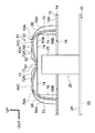
図1、図2、図4に示すように、サービスプラグカバー50のカバー本体52の上部を構成する天井部60は、車両上下方向下側(フロアパネル14側(図1及び図2))に凸となり、上面60Aに溝状の凹部62が形成されている。この溝状の凹部62は、端部62A,62Bが解放され、また車両前後方向を溝方向として形成されている。
また、図2に示すように、凹部62の溝方向(車両前後方向)と直交する断面形状は下側に凸の円弧状となっている。更に、図3に示すように、凹部62の底部64(図2参照)は、中央部64Cから車両前後方向の端部64A、64Bに向かうに従って下方に傾斜している(図1及び図4も参照)。言い換えると、凹部62の底部64の車両前後方向に沿った断面形状は、溝方向の中央部64Cが上側に膨らんだ山形になっている。
なお、図3では、凹部62の溝方向(車両前後方向)の中央(真ん中)が山の頂部となっているが、山の頂部が中央(真ん中)よりも車両前後方向前側や車両前後方向後側に位置するような形状であってもよい。
図1、図2、図4に示すように、サービスプラグカバー50のカバー本体52の車両幅方向両外側の側壁58の外面58Aには、それぞれ車両上下方向(側壁58の高さ方向)に沿って延在するリブ70が形成されている。リブ70は、側壁58の外面58Aに車両前後方向に間隔をあけて複数形成されている。
また、図2、図4に示すように、リブ70の上端部(最上部)70Aは、カバー本体52の天井部60の上面60Aの上端部(最上部)60Cを越えないように形成されている。
図5に示すように、サービスプラグカバー50の車両上下方向上側には、車両前後方向に沿って延在するダクト100が配置されている。このダクト100には、図示してないエアコンによって空調された空気が流れる。なお、このダクト100に流れる空調された空気は、図示していない後部座席に着座した乗員に向けて吹き付けられる。
サービスプラグカバー50のカバー本体52の天井部60の上面60Aとダクト100の下面102とは近接して配置されている。また、ダクト100の下面102には、緩衝部材の一例としてのスポンジ110が設けられている。よって、サービスプラグカバー50のカバー本体52の天井部60の上面60Aとダクト100の下面102との間には、スポンジ110が車両上下方向に弾性変形した状態で挟まれている。
なお、サービスプラグカバー50(ダクト100)の車両上下方向上側は、図示していないコンソールで覆われている。
<作用及び効果>
つぎに、本実施形態の作用及び効果について説明する。
つぎに、本実施形態の作用及び効果について説明する。
バッテリユニット20等のメンテナンス時には、ボルト98の締結を解除してサービスプラグカバー50を取り外し、バッテリユニット20の電気回路遮断装置26のサービスプラグ28を露出させる(図1参照)。車室内側から露出したサービスプラグ28を操作し、バッテリケース24に収納されたバッテリモジュール22の電気回路を電気的に遮断させて、バッテリユニット20等のメンテナンス作業を行う。
バッテリユニット20のメンテナンス作業が終了すると、車室内側からバッテリユニット20の電気回路遮断装置26のサービスプラグ28を操作し通電させる。そして、サービスプラグカバー50をボルト98によってフロアパネル14に締結する。
このようなメンテナンス時において、工具類が落下して樹脂製のサービスプラグカバー50の天井部60の上面60Aに当たり、天井部60に上方から荷重が入力される場合がある(図6A、図6BのF1を参照)。
また、車両走行時の振動や衝撃などによって、サービスプラグ28が天井部60の下面60Bに当たり、天井部60に下方から荷重が入力される場合がある(図6A、図6BのF2を参照)。
ここで、本実施形態のサービスプラグカバー50を示す図6A、図6B、図6Cと、比較例のサービスプラグカバー950を示す図10A、図10B、図10Cと、を用いて、天井部の変形について説明する。なお、図の想像線(二点破線)が、天井部が変形した状態を示している。また、図6A、図6B、図6Cでは、サービスプラグカバー50のカバー本体52のみを図示している。
図10A、図10B、図10Cに示す比較例のように、樹脂製のサービスプラグカバー950の天井部960が平坦である場合は、図10Bに示すように、サービスプラグカバー950の天井部960に上方から荷重F1が入力されると、天井部960は引張力Hが加わるように変形する。また、図10Cに示すように、サービスプラグカバー950の天井部960に下方から荷重F2が入力されると、天井部960は同様に引張力Hが加わるように変形する。このように樹脂製のサービスプラグカバー950の天井部960が引張変形する場合は、天井部960に割れや亀裂等の破損が発生しやすい。
これに対して、図6A、図6B、図6Cに示すように、本実施形態の樹脂製のサービスプラグカバー50の天井部60には、車両上下方向下側(フロアパネル14側)に凸となり上面60Aに溝状の凹部62が形成されている(図1~図4も参照)。
よって、図6Bに示すように、サービスプラグカバー50の天井部60に上方から荷重F1が入力されると、天井部60は圧縮力Pが加わるように変形する。なお、図では荷重F1は、凹部62の底部64に入力されるように見えるが、実際には工具類が落下すると凹部62の外側の上側に凸状になった凸状部分に先に当たるので、この凸状部分に荷重F1が入力される。よって、想像線(二点破線)で図示されているように、この凸状部分が平坦化するように変形、つまり圧縮力Pが加わるように変形する。
また、図6Cに示すように、サービスプラグカバー50の天井部60に下方から荷重F2が入力されると、天井部60は圧縮力Pが加わるように変形する。
そして、このように本実施形態の樹脂製のサービスプラグカバー50の天井部60が圧縮変形する場合は、図10A、図10B、図10Cに示す比較例のサービスプラグカバー950のように引張変形する場合と比較し、割れや亀裂等の破損が発生しにくい。
つまり、本実施形態の樹脂製のサービスプラグカバー50の天井部60に、車両上下方向下側(フロアパネル14側)に凸となり上面60Aに溝状の凹部62が形成されることで、天井部が平坦である場合と比較し、サービスプラグカバー50の強度が向上する。
また、天井部60の上面60Aの凹部62は、溝状であり、溝方向(車両前後方向)の端部62A、62Bは開放されている。よって、天井部60の凹部62に水が侵入しても、端部64A、64Bから排水される。
更に、凹部62の底部64は、中央部64Cから車両前後方向の端部64A、64Bに向かうに従って下方に傾斜している。言い換えると、凹部62の底部64の車両前後方向に沿った断面形状は、中央部64Cが上側に膨らんだ山形になっている(図3を参照)。よって、凹部62に侵入した水は、傾斜に沿って流れ、端部64A、64Bから排水される。よって、天井部60の凹部62に水が長期間に亘って貯留されることによる劣化が抑制又は防止される。また、天井部60の劣化に伴う強度低下が抑制又は防止される。
このように、天井部60が車両上下方向下側(フロアパネル14側)に凸となることで形成された上面60Aの溝状の凹部62は、サービスプラグカバー50の強度向上の機能と、排水機能と、の二つの機能を有している。よって、サービスプラグカバー50の天井部60の上面60Aの排水性能が確保されつつ、サービスプラグカバー50の強度が向上されている。
また、本実施形態では、サービスプラグカバー50の側壁58の外面58Aにリブ70が形成されているので、荷重F1及び荷重F2が加わった際の側壁58の変形が抑制され、サービスプラグカバー50の強度が、更に向上されている。
また、リブ70は、サービスプラグカバー50の側壁58の外面58Aに形成され、リブ70の上端部(最上部)70Aは、カバー本体52の天井部60の上面60Aの上端部(最上部)60Cを越えていない。よって、サービスプラグカバー50の天井部60の上面60Aにダクト100の下面102を近接して配置することがきる(図5を参照)。
なお、サービスプラグカバー50の天井部60の上面60Aとダクト100の下面102との間には、スポンジ110が挟まれている。よって、走行中の振動等で、サービスプラグカバー50の天井部60の上面60Aとダクト100の下面102とがスポンジ110を介して当たるので衝撃が緩衝され、サービスプラグカバー50及びダクト100の破損が防止される。
<本実施形態の変形例>
つぎに、上記実施形態の変形例について説明する。
つぎに、上記実施形態の変形例について説明する。
(第一変形例)
上記実施形態では、リブ70は、サービスプラグカバー50の側壁58の外面58Aに形成されていたが、これに限定されない。
上記実施形態では、リブ70は、サービスプラグカバー50の側壁58の外面58Aに形成されていたが、これに限定されない。
図7及び図8に示す第一変形例のサービスプラグカバー51のように、天井部60の上面60Aに凹部62の溝方向と交差する交差方向に沿って延在するリブ72を形成し、天井部60の下面60Bに凹部の62の溝方向と交差する交差方向に沿って延在するリブ74を形成し、側壁58の内面58Bに車両上下方向(側壁58の高さ方向)に沿って延在するリブ76が形成されていてもよい。なお、前述した交差方向は、本変形例では凹部62の溝方向と直交する直交方向であり、車両幅方向である。
また、これら、リブ72、74、76は、溝方向(車両前後方向)に間隔をあけて、複数形成されている。
なお、天井部60の上面60Aに形成したリブ72には、凹部62の底部64に相当する部位に、排水部の一例としての切欠部73が形成されている。また、このリブ72の略水平の上端部72Aの車両上下方向の位置は、天井部60の上端部60Cを越えないように形成されている。
このように、サービスプラグカバー50の側壁58の外面58Aのリブ70に加え、天井部60の上面60Aにリブ72が形成され、天井部60の下面60Bにリブ74が形成され、側壁58の内面58Bにリブ76が形成されている。よって、天井部60及び側壁58の変形が抑制され、サービスプラグカバー51の強度は、サービスプラグカバー50よりも向上されている。
また、天井部60の上面60Aのリブ72には、切欠部73が形成されているので、リブ72とリブ72との間に水が入っても、切欠部73から流れ、最終的に凹部62の端部64A、64Bから排水される。よって、天井部60の上面60Aに凹部62に交差するようにリブ72を形成しても、凹部62に水が長期間に亘って貯留されることによる劣化が抑制又は防止される。
なお、切欠部73以外、例えば、溝方向に貫通する貫通孔で排水される構成であってあってもよい。
また、リブ72の上端部72Aの車両上下方向の位置は、天井部60の上端部60Cを越えないように形成されている。よって、サービスプラグカバー50の天井部60の上面60Aとダクト100の下面102とを近接して配置することができる。
なお、上方に十分な空間を確保することが可能な場合や上方に近接する部材を配置しない場合等は、天井部60の上面60Aのリブ72の高さを高くし、つまり、天井部60の上端部60Cを越えるようにリブ72を形成し、更に強度が向上するようにしてもよい。
また、側壁58の外面58Aのリブ70、天井部60の上面60Aのリブ72、天井部60の下面60Bのリブ74、側壁58の内面58Bのリブ76の四つのリブのいずれか一つ又は複数が形成された構成であってもよい。或いは、これらのリブが形成されていない構成であってもよい。
(第二変形例及び第三変形例)
上記実施形態では、天井部60全体が下側に凸となることで、上面60Aの車両幅方向の中央部が凹んで、溝状の凹部62がひとつ形成されていたが、これに限定されない。
上記実施形態では、天井部60全体が下側に凸となることで、上面60Aの車両幅方向の中央部が凹んで、溝状の凹部62がひとつ形成されていたが、これに限定されない。
図9Aに示す第二変形例のサービスプラグカバー53のように、天井部60の一部(車両幅方向外側の部位(中央部から外側にずれた部位))が下側に凸となることで、上面60Aにおける車両幅方向外側の部位に、溝状の凹部92が形成されていてもよい。
また、図9Bに示す第三変形例のサービスプラグカバー55のように、溝状の凹部92が並んで二つ形成されていてもよい。図示は省略するが、凹部92が三つ以上並んで形成されていてもよい。
なお、この凹部92も底部94が、上記実施形態の凹部62のように、溝方向の中央部から両端部に向かうに従って下方に傾斜させることで、排水性能を向上させてもよい(図3を参照)。
また、図9Aに示す第二変形例のサービスプラグカバー53及び、図9Bに示す第三変形例のサービスプラグカバー55においても、図7及び図8に示す第二変形例のサービスプラグカバー51のように、側壁58の外面58Aのリブ70、側壁58の内面58Bのリブ76、天井部60の上面60Aのリブ72、天井部60の下面60Bのリブ74のいずれか一つ又は複数形成してもよい。なお、天井部60の上面60Aのリブ72には、凹部92の底部94に相当する部位に切欠部73を形成し、排水性能を確保する。
<その他>
尚、本発明は上記実施形態に限定されない。
尚、本発明は上記実施形態に限定されない。
例えば、上記実施形態及び変形例では、サービスプラグカバー50の天井部60の上面60Aとダクト100の下面102との間には、スポンジ110が挟まれていたが、これに限定されない。サービスプラグカバー50及びダクト100の破損を防止する緩衝機能(衝撃吸収機能)を有する部材であればよい。例えば、ゴム等の弾性部材であってもよいし、フェルトや発泡スチロール等であってもよい。
また、例えば、上記実施形態及び変形例では、溝状の凹部62、92は、天井部60の上面60Aに車両前後方向に沿って形成されていたが、これに限定されない。車両幅方向に沿って溝状の凹部が形成されていてもよいし、車両前後方向に対して角度を持って斜めに溝状の凹部が形成されていてもよい。
更に、複数の溝状の凹部が交差した構成であってもよい。例えば、天井部に車両前後方向に沿った凹部と車両幅方向に沿った凹部とが交差して形成されていてもよい。
また、上記実施形態及び変形例では、溝状の凹部62、92の底部64、94は、溝方向の中央部から両端部に向かうに従って下方に傾斜させることで、排水性能を向上させていたが、これに限定されない。凹部62、92の底部64、94を溝方向の一方の端部から他方の端部に向かうに従って下方に傾斜させることで、排水性能を向上させてもよい。なお、この場合、凹部の少なくとも他方の端部が、解放されていればよい。
更に、凹部62、92の底部64、94は、略水平に形成されていてもよい。なお、凹部62、92の底部64、94が略水平であっても、走行時の振動や坂道の走行の際に端部から排水される。
また、上記実施形態及び変形例では、サービスプラグカバー50は、フロアパネル14におけるサービスホール18の外周部に形成されたネジ孔96にボルト98を捩じ込めて締結することで、サービスプラグカバー50がフロアパネル14に着脱可能に設けられていたが、これに限定されない。
例えば、フロアパネル14におけるサービスホール18の外周部にウェルドナットを設けてボルトで締結してもよい。或いは、フロアパネル14におけるサービスホール18の外周部にスタッドボルトを設けてナットで締結してもよい。或いは、クリップで締結してもよい。要は、サービスプラグカバーが着脱可能にフロアパネル(車両用フロア)に設けられていればよい。
また、上記実施形態及び変形例では、サービスプラグカバー(サービスホールカバー)は、フロアパネル(車両フロア)の車両上下方向の下側に配置されたバッテリーユニット(車両用電池)のサービスプラグ(操作部)を操作するために形成したサービスホールを覆ったが、これに限定されない。
サービスプラグ以外の操作部を操作するために形成したサービスホールを覆うサービスホールカバーであってもよい。更に、その他、各種作業を行うために車両のパネルに形成したサービスホールを覆うサービスホールカバーにも本発明を適用することができる。
更に、本発明の要旨を逸脱しない範囲において種々なる態様で実施し得ることは言うまでもない。
Claims (9)
- 車両のパネルに形成されたサービスホールを覆うように、前記パネルに着脱可能に設けられ、下方側が開口した箱形状のカバー本体と、
前記カバー本体の上部を構成し、前記パネル側に凸となり上面に端部が解放された溝状の凹部が形成された天井部と、
を備えるサービスホールカバー。 - 前記凹部の底部は、溝方向の中央部から両端部に向かうに従って下方に傾斜され、又は溝方向の一方の端部から他方の端部に向かうに従って下方に傾斜されている、
請求項1に記載のサービスホールカバー。 - 前記カバー本体の側壁の外面には、側壁高さ方向に沿って延在する第一リブが形成されている、
請求項1又は請求項2に記載のサービスホールカバー。 - サービスホールが形成された車両フロアと、
前記車両フロアの車両上下方向の下側に配置された車両用ユニットに設けられ、前記サービスホールに向けて突出する操作部と、
前記車両フロアの上面に着脱可能に設けられた請求項1~請求項3のいずれか1項に記載のサービスホールカバーと、
前記サービスホールカバーの車両上下方向上側に配置されたダクトと、
前記ダクト側に設けられ、前記ダクトと前記サービスホールカバーとの間に挟まれた緩衝部材と、
を備える車両用ユニット搭載構造。 - 前記カバー本体の前記天井部の前記上面には、前記凹部の溝方向と交差する交差方向に沿って延在する第二リブが形成され、
前記第二リブの前記凹部に形成された部位には、溝方向に貫通する排水部が形成されている、
請求項1~請求項3のいずれか1項に記載のサービスホールカバー。 - 前記第二リブは、上端部が前記天井部の前記上面の上端部を越えないように形成されている、
請求項5に記載のサービスホールカバー。 - 前記カバー本体の側壁の内面には、側壁高さ方向に沿って延在する第三リブが形成されている、
請求項1~請求項3、請求項5、請求項6のいずれか1項に記載のサービスホールカバー。 - 前記カバー本体の前記天井部の下面には、前記凹部の溝方向と交差する交差方向に沿って延在する第四リブが形成されている、
請求項1~請求項3、請求項5~請求項7のいずれか1項に記載のサービスホールカバー。 - サービスホールが形成された車両フロアと、
前記車両フロアの車両上下方向の下側に配置された車両用ユニットに設けられ、前記サービスホールへ向けて突出する操作部と、
前記車両フロアの上面に着脱可能に設けられた請求項1~請求項3、請求項5~請求項8のいずれか1項に記載のサービスホールカバーと、
を備える車両用ユニット搭載構造。
Priority Applications (3)
| Application Number | Priority Date | Filing Date | Title |
|---|---|---|---|
| US14/426,069 US9676424B2 (en) | 2013-09-13 | 2014-06-18 | Service hole cover and unit mounting structure for vehicle |
| CN201480002594.8A CN104703827B (zh) | 2013-09-13 | 2014-06-18 | 检修孔盖体以及车辆用单元搭载结构 |
| EP14843710.6A EP3045335B1 (en) | 2013-09-13 | 2014-06-18 | Service hole cover and vehicle unit mounting structure |
Applications Claiming Priority (2)
| Application Number | Priority Date | Filing Date | Title |
|---|---|---|---|
| JP2013190599A JP5854012B2 (ja) | 2013-09-13 | 2013-09-13 | サービスホールカバー及び車両用ユニット搭載構造 |
| JP2013-190599 | 2013-09-13 |
Publications (1)
| Publication Number | Publication Date |
|---|---|
| WO2015037298A1 true WO2015037298A1 (ja) | 2015-03-19 |
Family
ID=52665423
Family Applications (1)
| Application Number | Title | Priority Date | Filing Date |
|---|---|---|---|
| PCT/JP2014/066209 Ceased WO2015037298A1 (ja) | 2013-09-13 | 2014-06-18 | サービスホールカバー及び車両用ユニット搭載構造 |
Country Status (5)
| Country | Link |
|---|---|
| US (1) | US9676424B2 (ja) |
| EP (1) | EP3045335B1 (ja) |
| JP (1) | JP5854012B2 (ja) |
| CN (1) | CN104703827B (ja) |
| WO (1) | WO2015037298A1 (ja) |
Families Citing this family (17)
| Publication number | Priority date | Publication date | Assignee | Title |
|---|---|---|---|---|
| FR3010383B1 (fr) * | 2013-09-06 | 2017-05-05 | Plastic Omnium Cie | Plancher de vehicule automobile avec peau superieure de renfort et ouverture d'accessibilite aux corps creux |
| DE102015103902A1 (de) * | 2015-03-17 | 2016-09-22 | Dr. Ing. H.C. F. Porsche Aktiengesellschaft | Unterboden eines Kraftfahrzeugs |
| JP6337860B2 (ja) * | 2015-09-15 | 2018-06-06 | トヨタ自動車株式会社 | 車両骨格構造 |
| JP6310951B2 (ja) * | 2016-01-27 | 2018-04-11 | 株式会社豊田自動織機 | 車両 |
| CN106184416B (zh) * | 2016-07-29 | 2019-02-12 | 奇瑞新能源汽车技术有限公司 | 电动汽车检修盖板总成 |
| JP6615072B2 (ja) * | 2016-09-02 | 2019-12-04 | 本田技研工業株式会社 | 電力機器ユニットのケース構造 |
| CN106314569B (zh) * | 2016-09-12 | 2019-03-12 | 北京汽车研究总院有限公司 | 一种可拆卸中通道结构及汽车 |
| JP6409842B2 (ja) * | 2016-09-28 | 2018-10-24 | トヨタ自動車株式会社 | 車両用構造体 |
| US11108147B2 (en) * | 2018-11-13 | 2021-08-31 | Honda Motor Co., Ltd. | Antenna protector |
| US11084537B2 (en) * | 2019-03-25 | 2021-08-10 | Honda Motor Co., Ltd. | Structural access panel |
| US11130392B2 (en) | 2019-05-20 | 2021-09-28 | Toyota Motor Engineering & Manufacturing North America, Inc. | Door service hole cover |
| CN110126926B (zh) * | 2019-06-04 | 2024-05-10 | 威马智慧出行科技(上海)有限公司 | 一种电池检修盖板结构及汽车 |
| JP2021046055A (ja) * | 2019-09-18 | 2021-03-25 | トヨタ自動車株式会社 | 車両床部構造 |
| US11325481B2 (en) | 2019-10-15 | 2022-05-10 | Toyota Motor Engineering & Manufacturing North America, Inc. | Cover assembly for service plug socket |
| JP2023002335A (ja) * | 2021-06-22 | 2023-01-10 | トヨタ自動車株式会社 | 運転席周辺構造 |
| JP7809029B2 (ja) * | 2022-08-03 | 2026-01-30 | 株式会社クボタ | 作業車 |
| KR20240084897A (ko) * | 2022-12-07 | 2024-06-14 | 현대자동차주식회사 | 리어 플로어 패널의 보강 부재 |
Citations (6)
| Publication number | Priority date | Publication date | Assignee | Title |
|---|---|---|---|---|
| JPH11321481A (ja) * | 1998-05-14 | 1999-11-24 | Araco Corp | 車両用ウエザストリップ |
| JP2001048057A (ja) * | 1999-08-03 | 2001-02-20 | Nissan Motor Co Ltd | 自動車の車体後部構造 |
| JP2009083601A (ja) | 2007-09-28 | 2009-04-23 | Mitsubishi Motors Corp | 電気自動車 |
| JP2012240476A (ja) * | 2011-05-17 | 2012-12-10 | Nissan Motor Co Ltd | 電気自動車のバッテリパック構造 |
| JP2013107542A (ja) | 2011-11-22 | 2013-06-06 | Toyota Motor Corp | サービスホールカバー取付構造、及びこれを備えた車両用電池搭載構造 |
| JP2013112225A (ja) | 2011-11-29 | 2013-06-10 | Toyota Motor Corp | 車両用電池搭載構造 |
Family Cites Families (9)
| Publication number | Priority date | Publication date | Assignee | Title |
|---|---|---|---|---|
| JPS5830821A (ja) * | 1981-08-20 | 1983-02-23 | Seikou Shokai:Kk | エアボツクス構造 |
| JPH09226483A (ja) * | 1996-02-29 | 1997-09-02 | Toyota Motor Corp | 電気自動車のバッテリ収納機構 |
| CN2626768Y (zh) * | 2003-07-22 | 2004-07-21 | 谭志坚 | 电动自行车的电池盒 |
| JP4935112B2 (ja) * | 2006-02-28 | 2012-05-23 | トヨタ自動車株式会社 | 蓄電パックの車載構造 |
| US8313121B2 (en) * | 2008-09-29 | 2012-11-20 | Deakin University | Chassis for pneumatic vehicle |
| MX2011008831A (es) * | 2009-02-24 | 2011-09-21 | Nissan Motor | Estructura de montaje de bateria de vehiculo. |
| JP5498890B2 (ja) * | 2009-11-12 | 2014-05-21 | 株式会社ニフコ | 自動車用の閉塞栓 |
| CN202308106U (zh) * | 2011-06-29 | 2012-07-04 | 杭州市电力局 | 一种电动汽车动力电池和电动汽车 |
| CN202439766U (zh) * | 2012-01-06 | 2012-09-19 | 中国重汽集团济南动力有限公司 | 一种多道密封检修盖 |
-
2013
- 2013-09-13 JP JP2013190599A patent/JP5854012B2/ja active Active
-
2014
- 2014-06-18 EP EP14843710.6A patent/EP3045335B1/en active Active
- 2014-06-18 WO PCT/JP2014/066209 patent/WO2015037298A1/ja not_active Ceased
- 2014-06-18 CN CN201480002594.8A patent/CN104703827B/zh active Active
- 2014-06-18 US US14/426,069 patent/US9676424B2/en active Active
Patent Citations (6)
| Publication number | Priority date | Publication date | Assignee | Title |
|---|---|---|---|---|
| JPH11321481A (ja) * | 1998-05-14 | 1999-11-24 | Araco Corp | 車両用ウエザストリップ |
| JP2001048057A (ja) * | 1999-08-03 | 2001-02-20 | Nissan Motor Co Ltd | 自動車の車体後部構造 |
| JP2009083601A (ja) | 2007-09-28 | 2009-04-23 | Mitsubishi Motors Corp | 電気自動車 |
| JP2012240476A (ja) * | 2011-05-17 | 2012-12-10 | Nissan Motor Co Ltd | 電気自動車のバッテリパック構造 |
| JP2013107542A (ja) | 2011-11-22 | 2013-06-06 | Toyota Motor Corp | サービスホールカバー取付構造、及びこれを備えた車両用電池搭載構造 |
| JP2013112225A (ja) | 2011-11-29 | 2013-06-10 | Toyota Motor Corp | 車両用電池搭載構造 |
Also Published As
| Publication number | Publication date |
|---|---|
| EP3045335A1 (en) | 2016-07-20 |
| JP5854012B2 (ja) | 2016-02-09 |
| EP3045335A4 (en) | 2016-09-07 |
| US20160176445A1 (en) | 2016-06-23 |
| CN104703827A (zh) | 2015-06-10 |
| JP2015054667A (ja) | 2015-03-23 |
| EP3045335B1 (en) | 2018-10-17 |
| US9676424B2 (en) | 2017-06-13 |
| CN104703827B (zh) | 2018-03-30 |
Similar Documents
| Publication | Publication Date | Title |
|---|---|---|
| JP5854012B2 (ja) | サービスホールカバー及び車両用ユニット搭載構造 | |
| CN104553717B (zh) | 电动车辆 | |
| JP5165491B2 (ja) | リヤコンソール | |
| CN110588312B (zh) | 车身下部结构体 | |
| CN101395022B (zh) | 蓄电组的车载构造 | |
| JP6307919B2 (ja) | 車両における高圧電線の配設構造 | |
| EP2033879A1 (en) | Vehicle front structure | |
| KR102440612B1 (ko) | 측방 차체 보강구조 | |
| CN102555754B (zh) | 车辆的线束设置结构 | |
| JP5984052B2 (ja) | 電池パックの位置決めピンブラケット | |
| JP2013147137A (ja) | 電動車両のフロア構造 | |
| JP2020032738A (ja) | 車両下部構造 | |
| JP2007331719A (ja) | 高圧電装部品設置構造 | |
| JP7331759B2 (ja) | 電動車両の下部構造 | |
| JP2019166850A (ja) | 側面衝撃対応の車体構造 | |
| JP6364651B2 (ja) | アンダーカバー構造 | |
| KR20110000431A (ko) | 자동차의 대쉬패널 | |
| JP2009269522A (ja) | コンソールボックス | |
| CN204586750U (zh) | 车载电池的安装结构 | |
| JP6530932B2 (ja) | 車両 | |
| JP5347613B2 (ja) | 自動車の車体構造 | |
| JP2008195090A (ja) | 車両用電池機器の搭載構造 | |
| JP4172030B2 (ja) | 自動車のルーフ構造 | |
| JP2009067147A (ja) | 前部車体構造 | |
| JP2021017123A (ja) | 電動車両のスペアタイヤ取付け構造 |
Legal Events
| Date | Code | Title | Description |
|---|---|---|---|
| WWE | Wipo information: entry into national phase |
Ref document number: 14426069 Country of ref document: US |
|
| REEP | Request for entry into the european phase |
Ref document number: 2014843710 Country of ref document: EP |
|
| WWE | Wipo information: entry into national phase |
Ref document number: 2014843710 Country of ref document: EP |
|
| 121 | Ep: the epo has been informed by wipo that ep was designated in this application |
Ref document number: 14843710 Country of ref document: EP Kind code of ref document: A1 |
|
| NENP | Non-entry into the national phase |
Ref country code: DE |