WO2015041132A1 - 金属めっき被覆ステンレス材、および金属めっき被覆ステンレス材の製造方法 - Google Patents
金属めっき被覆ステンレス材、および金属めっき被覆ステンレス材の製造方法 Download PDFInfo
- Publication number
- WO2015041132A1 WO2015041132A1 PCT/JP2014/074053 JP2014074053W WO2015041132A1 WO 2015041132 A1 WO2015041132 A1 WO 2015041132A1 JP 2014074053 W JP2014074053 W JP 2014074053W WO 2015041132 A1 WO2015041132 A1 WO 2015041132A1
- Authority
- WO
- WIPO (PCT)
- Prior art keywords
- stainless steel
- plating layer
- steel material
- metal
- metal plating
- Prior art date
- Legal status (The legal status is an assumption and is not a legal conclusion. Google has not performed a legal analysis and makes no representation as to the accuracy of the status listed.)
- Ceased
Links
Images


Classifications
-
- C—CHEMISTRY; METALLURGY
- C23—COATING METALLIC MATERIAL; COATING MATERIAL WITH METALLIC MATERIAL; CHEMICAL SURFACE TREATMENT; DIFFUSION TREATMENT OF METALLIC MATERIAL; COATING BY VACUUM EVAPORATION, BY SPUTTERING, BY ION IMPLANTATION OR BY CHEMICAL VAPOUR DEPOSITION, IN GENERAL; INHIBITING CORROSION OF METALLIC MATERIAL OR INCRUSTATION IN GENERAL
- C23C—COATING METALLIC MATERIAL; COATING MATERIAL WITH METALLIC MATERIAL; SURFACE TREATMENT OF METALLIC MATERIAL BY DIFFUSION INTO THE SURFACE, BY CHEMICAL CONVERSION OR SUBSTITUTION; COATING BY VACUUM EVAPORATION, BY SPUTTERING, BY ION IMPLANTATION OR BY CHEMICAL VAPOUR DEPOSITION, IN GENERAL
- C23C18/00—Chemical coating by decomposition of either liquid compounds or solutions of the coating forming compounds, without leaving reaction products of surface material in the coating; Contact plating
- C23C18/16—Chemical coating by decomposition of either liquid compounds or solutions of the coating forming compounds, without leaving reaction products of surface material in the coating; Contact plating by reduction or substitution, e.g. electroless plating
- C23C18/18—Pretreatment of the material to be coated
- C23C18/1803—Pretreatment of the material to be coated of metallic material surfaces or of a non-specific material surfaces
- C23C18/1824—Pretreatment of the material to be coated of metallic material surfaces or of a non-specific material surfaces by chemical pretreatment
- C23C18/1827—Pretreatment of the material to be coated of metallic material surfaces or of a non-specific material surfaces by chemical pretreatment only one step pretreatment
-
- C—CHEMISTRY; METALLURGY
- C23—COATING METALLIC MATERIAL; COATING MATERIAL WITH METALLIC MATERIAL; CHEMICAL SURFACE TREATMENT; DIFFUSION TREATMENT OF METALLIC MATERIAL; COATING BY VACUUM EVAPORATION, BY SPUTTERING, BY ION IMPLANTATION OR BY CHEMICAL VAPOUR DEPOSITION, IN GENERAL; INHIBITING CORROSION OF METALLIC MATERIAL OR INCRUSTATION IN GENERAL
- C23C—COATING METALLIC MATERIAL; COATING MATERIAL WITH METALLIC MATERIAL; SURFACE TREATMENT OF METALLIC MATERIAL BY DIFFUSION INTO THE SURFACE, BY CHEMICAL CONVERSION OR SUBSTITUTION; COATING BY VACUUM EVAPORATION, BY SPUTTERING, BY ION IMPLANTATION OR BY CHEMICAL VAPOUR DEPOSITION, IN GENERAL
- C23C18/00—Chemical coating by decomposition of either liquid compounds or solutions of the coating forming compounds, without leaving reaction products of surface material in the coating; Contact plating
- C23C18/16—Chemical coating by decomposition of either liquid compounds or solutions of the coating forming compounds, without leaving reaction products of surface material in the coating; Contact plating by reduction or substitution, e.g. electroless plating
- C23C18/31—Coating with metals
- C23C18/42—Coating with noble metals
-
- B—PERFORMING OPERATIONS; TRANSPORTING
- B32—LAYERED PRODUCTS
- B32B—LAYERED PRODUCTS, i.e. PRODUCTS BUILT-UP OF STRATA OF FLAT OR NON-FLAT, e.g. CELLULAR OR HONEYCOMB, FORM
- B32B15/00—Layered products comprising a layer of metal
- B32B15/01—Layered products comprising a layer of metal all layers being exclusively metallic
- B32B15/013—Layered products comprising a layer of metal all layers being exclusively metallic one layer being formed of an iron alloy or steel, another layer being formed of a metal other than iron or aluminium
-
- B—PERFORMING OPERATIONS; TRANSPORTING
- B32—LAYERED PRODUCTS
- B32B—LAYERED PRODUCTS, i.e. PRODUCTS BUILT-UP OF STRATA OF FLAT OR NON-FLAT, e.g. CELLULAR OR HONEYCOMB, FORM
- B32B15/00—Layered products comprising a layer of metal
- B32B15/01—Layered products comprising a layer of metal all layers being exclusively metallic
- B32B15/018—Layered products comprising a layer of metal all layers being exclusively metallic one layer being formed of a noble metal or a noble metal alloy
-
- C—CHEMISTRY; METALLURGY
- C23—COATING METALLIC MATERIAL; COATING MATERIAL WITH METALLIC MATERIAL; CHEMICAL SURFACE TREATMENT; DIFFUSION TREATMENT OF METALLIC MATERIAL; COATING BY VACUUM EVAPORATION, BY SPUTTERING, BY ION IMPLANTATION OR BY CHEMICAL VAPOUR DEPOSITION, IN GENERAL; INHIBITING CORROSION OF METALLIC MATERIAL OR INCRUSTATION IN GENERAL
- C23C—COATING METALLIC MATERIAL; COATING MATERIAL WITH METALLIC MATERIAL; SURFACE TREATMENT OF METALLIC MATERIAL BY DIFFUSION INTO THE SURFACE, BY CHEMICAL CONVERSION OR SUBSTITUTION; COATING BY VACUUM EVAPORATION, BY SPUTTERING, BY ION IMPLANTATION OR BY CHEMICAL VAPOUR DEPOSITION, IN GENERAL
- C23C18/00—Chemical coating by decomposition of either liquid compounds or solutions of the coating forming compounds, without leaving reaction products of surface material in the coating; Contact plating
- C23C18/16—Chemical coating by decomposition of either liquid compounds or solutions of the coating forming compounds, without leaving reaction products of surface material in the coating; Contact plating by reduction or substitution, e.g. electroless plating
- C23C18/18—Pretreatment of the material to be coated
- C23C18/1803—Pretreatment of the material to be coated of metallic material surfaces or of a non-specific material surfaces
- C23C18/1824—Pretreatment of the material to be coated of metallic material surfaces or of a non-specific material surfaces by chemical pretreatment
- C23C18/1827—Pretreatment of the material to be coated of metallic material surfaces or of a non-specific material surfaces by chemical pretreatment only one step pretreatment
- C23C18/1834—Use of organic or inorganic compounds other than metals, e.g. activation, sensitisation with polymers
-
- C—CHEMISTRY; METALLURGY
- C23—COATING METALLIC MATERIAL; COATING MATERIAL WITH METALLIC MATERIAL; CHEMICAL SURFACE TREATMENT; DIFFUSION TREATMENT OF METALLIC MATERIAL; COATING BY VACUUM EVAPORATION, BY SPUTTERING, BY ION IMPLANTATION OR BY CHEMICAL VAPOUR DEPOSITION, IN GENERAL; INHIBITING CORROSION OF METALLIC MATERIAL OR INCRUSTATION IN GENERAL
- C23C—COATING METALLIC MATERIAL; COATING MATERIAL WITH METALLIC MATERIAL; SURFACE TREATMENT OF METALLIC MATERIAL BY DIFFUSION INTO THE SURFACE, BY CHEMICAL CONVERSION OR SUBSTITUTION; COATING BY VACUUM EVAPORATION, BY SPUTTERING, BY ION IMPLANTATION OR BY CHEMICAL VAPOUR DEPOSITION, IN GENERAL
- C23C18/00—Chemical coating by decomposition of either liquid compounds or solutions of the coating forming compounds, without leaving reaction products of surface material in the coating; Contact plating
- C23C18/16—Chemical coating by decomposition of either liquid compounds or solutions of the coating forming compounds, without leaving reaction products of surface material in the coating; Contact plating by reduction or substitution, e.g. electroless plating
- C23C18/31—Coating with metals
-
- C—CHEMISTRY; METALLURGY
- C23—COATING METALLIC MATERIAL; COATING MATERIAL WITH METALLIC MATERIAL; CHEMICAL SURFACE TREATMENT; DIFFUSION TREATMENT OF METALLIC MATERIAL; COATING BY VACUUM EVAPORATION, BY SPUTTERING, BY ION IMPLANTATION OR BY CHEMICAL VAPOUR DEPOSITION, IN GENERAL; INHIBITING CORROSION OF METALLIC MATERIAL OR INCRUSTATION IN GENERAL
- C23C—COATING METALLIC MATERIAL; COATING MATERIAL WITH METALLIC MATERIAL; SURFACE TREATMENT OF METALLIC MATERIAL BY DIFFUSION INTO THE SURFACE, BY CHEMICAL CONVERSION OR SUBSTITUTION; COATING BY VACUUM EVAPORATION, BY SPUTTERING, BY ION IMPLANTATION OR BY CHEMICAL VAPOUR DEPOSITION, IN GENERAL
- C23C18/00—Chemical coating by decomposition of either liquid compounds or solutions of the coating forming compounds, without leaving reaction products of surface material in the coating; Contact plating
- C23C18/16—Chemical coating by decomposition of either liquid compounds or solutions of the coating forming compounds, without leaving reaction products of surface material in the coating; Contact plating by reduction or substitution, e.g. electroless plating
- C23C18/31—Coating with metals
- C23C18/38—Coating with copper
-
- C—CHEMISTRY; METALLURGY
- C23—COATING METALLIC MATERIAL; COATING MATERIAL WITH METALLIC MATERIAL; CHEMICAL SURFACE TREATMENT; DIFFUSION TREATMENT OF METALLIC MATERIAL; COATING BY VACUUM EVAPORATION, BY SPUTTERING, BY ION IMPLANTATION OR BY CHEMICAL VAPOUR DEPOSITION, IN GENERAL; INHIBITING CORROSION OF METALLIC MATERIAL OR INCRUSTATION IN GENERAL
- C23C—COATING METALLIC MATERIAL; COATING MATERIAL WITH METALLIC MATERIAL; SURFACE TREATMENT OF METALLIC MATERIAL BY DIFFUSION INTO THE SURFACE, BY CHEMICAL CONVERSION OR SUBSTITUTION; COATING BY VACUUM EVAPORATION, BY SPUTTERING, BY ION IMPLANTATION OR BY CHEMICAL VAPOUR DEPOSITION, IN GENERAL
- C23C18/00—Chemical coating by decomposition of either liquid compounds or solutions of the coating forming compounds, without leaving reaction products of surface material in the coating; Contact plating
- C23C18/16—Chemical coating by decomposition of either liquid compounds or solutions of the coating forming compounds, without leaving reaction products of surface material in the coating; Contact plating by reduction or substitution, e.g. electroless plating
- C23C18/48—Coating with alloys
-
- C—CHEMISTRY; METALLURGY
- C23—COATING METALLIC MATERIAL; COATING MATERIAL WITH METALLIC MATERIAL; CHEMICAL SURFACE TREATMENT; DIFFUSION TREATMENT OF METALLIC MATERIAL; COATING BY VACUUM EVAPORATION, BY SPUTTERING, BY ION IMPLANTATION OR BY CHEMICAL VAPOUR DEPOSITION, IN GENERAL; INHIBITING CORROSION OF METALLIC MATERIAL OR INCRUSTATION IN GENERAL
- C23C—COATING METALLIC MATERIAL; COATING MATERIAL WITH METALLIC MATERIAL; SURFACE TREATMENT OF METALLIC MATERIAL BY DIFFUSION INTO THE SURFACE, BY CHEMICAL CONVERSION OR SUBSTITUTION; COATING BY VACUUM EVAPORATION, BY SPUTTERING, BY ION IMPLANTATION OR BY CHEMICAL VAPOUR DEPOSITION, IN GENERAL
- C23C22/00—Chemical surface treatment of metallic material by reaction of the surface with a reactive liquid, leaving reaction products of surface material in the coating, e.g. conversion coatings, passivation of metals
- C23C22/05—Chemical surface treatment of metallic material by reaction of the surface with a reactive liquid, leaving reaction products of surface material in the coating, e.g. conversion coatings, passivation of metals using aqueous solutions
- C23C22/06—Chemical surface treatment of metallic material by reaction of the surface with a reactive liquid, leaving reaction products of surface material in the coating, e.g. conversion coatings, passivation of metals using aqueous solutions using aqueous acidic solutions with pH less than 6
- C23C22/48—Chemical surface treatment of metallic material by reaction of the surface with a reactive liquid, leaving reaction products of surface material in the coating, e.g. conversion coatings, passivation of metals using aqueous solutions using aqueous acidic solutions with pH less than 6 not containing phosphates, hexavalent chromium compounds, fluorides or complex fluorides, molybdates, tungstates, vanadates or oxalates
- C23C22/50—Treatment of iron or alloys based thereon
-
- C—CHEMISTRY; METALLURGY
- C23—COATING METALLIC MATERIAL; COATING MATERIAL WITH METALLIC MATERIAL; CHEMICAL SURFACE TREATMENT; DIFFUSION TREATMENT OF METALLIC MATERIAL; COATING BY VACUUM EVAPORATION, BY SPUTTERING, BY ION IMPLANTATION OR BY CHEMICAL VAPOUR DEPOSITION, IN GENERAL; INHIBITING CORROSION OF METALLIC MATERIAL OR INCRUSTATION IN GENERAL
- C23C—COATING METALLIC MATERIAL; COATING MATERIAL WITH METALLIC MATERIAL; SURFACE TREATMENT OF METALLIC MATERIAL BY DIFFUSION INTO THE SURFACE, BY CHEMICAL CONVERSION OR SUBSTITUTION; COATING BY VACUUM EVAPORATION, BY SPUTTERING, BY ION IMPLANTATION OR BY CHEMICAL VAPOUR DEPOSITION, IN GENERAL
- C23C28/00—Coating for obtaining at least two superposed coatings either by methods not provided for in a single one of groups C23C2/00 - C23C26/00 or by combinations of methods provided for in subclasses C23C and C25C or C25D
- C23C28/30—Coatings combining at least one metallic layer and at least one inorganic non-metallic layer
- C23C28/32—Coatings combining at least one metallic layer and at least one inorganic non-metallic layer including at least one pure metallic layer
- C23C28/322—Coatings combining at least one metallic layer and at least one inorganic non-metallic layer including at least one pure metallic layer only coatings of metal elements only
-
- C—CHEMISTRY; METALLURGY
- C23—COATING METALLIC MATERIAL; COATING MATERIAL WITH METALLIC MATERIAL; CHEMICAL SURFACE TREATMENT; DIFFUSION TREATMENT OF METALLIC MATERIAL; COATING BY VACUUM EVAPORATION, BY SPUTTERING, BY ION IMPLANTATION OR BY CHEMICAL VAPOUR DEPOSITION, IN GENERAL; INHIBITING CORROSION OF METALLIC MATERIAL OR INCRUSTATION IN GENERAL
- C23C—COATING METALLIC MATERIAL; COATING MATERIAL WITH METALLIC MATERIAL; SURFACE TREATMENT OF METALLIC MATERIAL BY DIFFUSION INTO THE SURFACE, BY CHEMICAL CONVERSION OR SUBSTITUTION; COATING BY VACUUM EVAPORATION, BY SPUTTERING, BY ION IMPLANTATION OR BY CHEMICAL VAPOUR DEPOSITION, IN GENERAL
- C23C28/00—Coating for obtaining at least two superposed coatings either by methods not provided for in a single one of groups C23C2/00 - C23C26/00 or by combinations of methods provided for in subclasses C23C and C25C or C25D
- C23C28/30—Coatings combining at least one metallic layer and at least one inorganic non-metallic layer
- C23C28/34—Coatings combining at least one metallic layer and at least one inorganic non-metallic layer including at least one inorganic non-metallic material layer, e.g. metal carbide, nitride, boride, silicide layer and their mixtures, enamels, phosphates and sulphates
-
- C—CHEMISTRY; METALLURGY
- C25—ELECTROLYTIC OR ELECTROPHORETIC PROCESSES; APPARATUS THEREFOR
- C25D—PROCESSES FOR THE ELECTROLYTIC OR ELECTROPHORETIC PRODUCTION OF COATINGS; ELECTROFORMING; APPARATUS THEREFOR
- C25D3/00—Electroplating: Baths therefor
- C25D3/02—Electroplating: Baths therefor from solutions
- C25D3/46—Electroplating: Baths therefor from solutions of silver
Definitions
- the present invention relates to a metal plating coated stainless steel material and a metal plating coated stainless steel material.
- any one of Ag, Pd, Pt, Rh, Ru, Cu, Sn, Cr, or these metals on the surface of a stainless steel plate Of these, a metal plating coated stainless steel coated with a metal plating layer composed of an alloy composed of at least two or more metals is used.
- Patent Document 1 discloses a technique for directly forming a gold plating layer on a stainless steel plate without performing such base nickel plating.
- the present invention has been made in view of such a situation, and even when the metal plating layer on the surface is thinned, the coverage and adhesion of the metal plating layer can be improved. It is another object of the present invention to provide a metal plating coated stainless steel material that is excellent in conductivity and advantageous in cost.
- the present inventors have found that the above object can be achieved by forming a predetermined passive film on a stainless steel plate and forming a metal plating layer on the passive film.
- the inventor has completed the present invention.
- a passive film having a Cr / O value of 0.05 to 0.2 and a Cr / Fe value of 0.5 to 0.8 on the surface by Auger electron spectroscopy is formed.
- Stainless steel plate, and any one of Ag, Pd, Pt, Rh, Ru, Cu, Sn, and Cr formed on the stainless steel plate, or at least two of these metals A metal plating coated stainless steel material comprising: a metal plating layer comprising:
- the metal plating layer preferably has a coverage of 95% or more.
- the sulfuric acid concentration at the time of immersion is x [volume%] (where 20 ⁇ x ⁇ 25), the temperature is y [° C.], and the immersion time is z [seconds], the following formula (1) is satisfied.
- a method for producing a metal-plated coated stainless steel material is provided.
- the Cr / O value by Auger electron spectroscopy analysis on the surface of the stainless steel plate is 0.05 to 0.2
- Cr / Fe A dipping process for forming a passive film having a value in the range of 0.5 to 0.8, and Ag, Pd, Pt, Rh, Ru, Cu, Sn, Cr on the passive film of the stainless steel plate
- a method for producing a metal-plated stainless steel material comprising a plating step of forming a metal plating layer composed of any one metal or an alloy composed of at least two of these metals. .
- the metal plating layer formed on the stainless steel plate can be improved in coverage and adhesion even when the thickness is reduced, thereby being excellent in corrosion resistance and conductivity, and cost-effective.
- An advantageous metal-plated stainless steel material can be provided.
- FIG. 1 is a configuration diagram of a metal plating coated stainless steel material 100 according to the present embodiment.
- FIG. 2 is a graph showing the results of measurement by X-ray photoelectron spectroscopy (XPS) of the passive film 11 of the stainless steel plate 10 obtained in Examples and Comparative Examples.
- FIG. 3 is a graph showing the results of measuring the Cr / O value and the Cr / Fe value by Auger electron spectroscopy analysis on the surface of the passive film 11 of the stainless steel plate 10 obtained in Examples and Comparative Examples.
- FIG. 4 is a diagram showing the results of measuring the surface roughness of the passive film 11 of the stainless steel plate 10 obtained in Examples and Comparative Examples.
- FIG. XPS X-ray photoelectron spectroscopy
- FIG. 5 is a graph showing the results of XRD analysis using an X-ray diffractometer for the passive film 11 of the stainless steel plate 10 obtained in the example.
- FIG. 6 is a cross-sectional photograph of the passive film 11 of the stainless steel plate 10 obtained in Examples and Comparative Examples.
- FIG. 7 is a diagram showing electron beam diffraction patterns in the passive film 11 of the stainless steel plate 10 obtained in the examples and comparative examples.
- FIG. 8 is a SEM photograph of the surface of the metal plating coated stainless steel 100 obtained in the example.
- FIG. 9 is a diagram for explaining a method of measuring the contact resistance of the metal plating coated stainless steel material 100 obtained in the example.
- FIG. 10 is a graph showing the results of measuring the contact resistance of the metal plating coated stainless steel material 100 obtained in the example.
- the metal plating coated stainless steel material 100 of the present embodiment is made of Ag, Pd, Pt, Rh, Ru, Cu, Sn, Cr on the stainless steel plate 10 on which the passive film 11 is formed.
- the metal plating layer 20 made of any one metal or an alloy made of at least two of these metals is formed, and the passive film 11 of the stainless steel plate 10 has an Auger electron spectroscopic analysis on the surface.
- the Cr / O value is 0.05 to 0.2 and the Cr / Fe value is 0.5 to 0.8.
- stainless steel plate 10 Although it does not specifically limit as the stainless steel plate 10 used as the board
- the shape of the stainless steel plate 10 is not particularly limited and can be appropriately selected depending on the intended use. For example, a conductive metal part or plate processed into a linear shape or plate shape is processed into an uneven shape.
- the thickness (diameter) and thickness (plate thickness) of the stainless steel plate 10 are not particularly limited, and can be appropriately selected according to the intended use.
- the stainless steel plate 10 has a passive film 11 formed on the surface.
- the passive film 11 has a Cr / O value (Cr / O molar ratio) and a Cr / Fe value (Cr / Fe molar ratio) by the Auger electron spectroscopic analysis on the surface in the following ranges. . That is, the Cr / O value is in the range of 0.05 to 0.2, preferably 0.05 to 0.15.
- the Cr / Fe value is in the range of 0.5 to 0.8, preferably 0.5 to 0.7.
- the surface of the passive film 11 formed on the stainless steel plate 10 is formed on the passive film 11 by controlling the Cr / O value and the Cr / Fe value by Auger electron spectroscopy analysis within the above ranges.
- the coverage ratio that is, the ratio of the area covered with the metal plating layer 20 on the surface on which the metal plating layer 20 is formed on the passive film 11
- the adhesion is also improved. It will be excellent.
- the Cr / O value and the Cr / Fe value by Auger electron spectroscopy can be measured by the following method, for example. That is, first, the surface of the passive film 11 is measured using a scanning Auger electron spectrometer (AES), and the atomic% of Cr, O, and Fe on the surface of the passive film 11 is calculated. And about 5 places among the surfaces of the passive film 11, the measurement by a scanning Auger electron spectrometer is performed, and the obtained results are averaged to obtain a Cr / O value (atomic% of Cr / atomic of O). %) And Cr / Fe value (Cr atomic% / Fe atomic%) can be calculated.
- AES scanning Auger electron spectrometer
- a peak at 510 to 535 eV is a Cr peak
- a peak at 485 to 520 eV is an O peak
- 570 The atomic% of Cr, O, and Fe is measured by setting the peak at ⁇ 600 eV as the Fe peak and the total of Cr, O, and Fe as 100 atomic%.
- the method of forming the passive film 11 on the surface of the stainless steel plate 10 is not particularly limited.
- the sulfuric acid concentration of the sulfuric acid aqueous solution is preferably 20 to 25% by volume.
- the temperature at which the stainless steel material is immersed is preferably 50 to 70 ° C., more preferably 60 to 70 ° C.
- the time for immersing the stainless steel material in the sulfuric acid aqueous solution is preferably 5 to 600 seconds, more preferably 5 to 300 seconds.
- the immersion temperature is y [° C.]
- the immersion time is When z is z [seconds], it is preferable to satisfy the following formula (1).
- the passive film 11 when a method of immersing a stainless steel material in an aqueous sulfuric acid solution is used to form the passive film 11, the sulfuric acid concentration x [volume%], the temperature y [° C.], and the immersion time z [
- the oxide film originally formed on the surface of the stainless steel material is removed, and Cr / O by surface Auger electron spectroscopy analysis is performed on the stainless steel material.
- the passive film 11 in which the value and the Cr / Fe value are controlled in the above-described range can be formed.
- the metal plating layer 20 is a layer formed by performing a plating process on the passive film 11 of the stainless steel plate 10.
- the metal constituting the metal plating layer 20 includes silver (Ag), palladium (Pd), platinum (Pt), rhodium (Rh), ruthenium (Ru), copper (Cu), tin Any one of (Sn) and chromium (Cr), or an alloy composed of at least two of these metals can be used, and among these, Ag, Pd, or Pt is particularly preferable.
- the plating method for forming the metal plating layer 20 is not particularly limited, but it is formed by electroless plating using a plating bath containing a salt such as Ag, Pd, Pt, Rh, Ru, Cu, Sn, or Cr. Is preferred.
- the obtained metal plating coated stainless steel material 100 has a plating property and adhesiveness of the metal plating layer 20 as described later. It will be excellent in corrosion resistance and conductivity.
- the coverage of the metal plating layer 20, that is, the ratio of the area covered with the metal plating layer 20 on the surface on which the metal plating layer 20 is formed on the passive film 11 is preferably 95% or more. is there.
- the coverage of the metal plating layer 20 is preferably 95% or more.
- the thickness of the metal plating layer 20 is preferably 10 to 200 nm, more preferably 20 to 100 nm. If the thickness of the metal plating layer 20 mainly made of silver is too thin, the uniform metal plating layer 20 is not formed on the passive film 11 of the stainless steel plate 10, and when used as the metal plating coated stainless steel material 100, the corrosion resistance and There is a possibility that the conductivity is lowered. On the other hand, when the thickness of the metal plating layer 20 is too thick, it is disadvantageous in terms of cost.
- the thickness of the metal plating layer 20 is preferably 2 to 20 nm, more preferably 2 to 5 nm.
- the uniform metal plating layer 20 is not formed on the passive film 11 of the stainless steel plate 10 and is used as the metal plating coated stainless material 100. In addition, corrosion resistance and conductivity may be reduced.
- the thickness of the metal plating layer 20 is too thick, it is disadvantageous in terms of cost.
- the metal plating coated stainless steel material 100 can be obtained.
- the Cr / O value and the Cr / Fe value obtained by Auger electron spectroscopic analysis of the surface of the passive film 11 formed on the stainless steel plate 10 are as described above. Since the range is controlled, the coverage and adhesion of the metal plating layer 20 formed on such a passive film 11 can be improved.
- the metal plating coated stainless steel material 100 of the present embodiment has high coverage and adhesion of the metal plating layer 20 even when the metal plating layer 20 on the surface is thinned, thereby improving corrosion resistance and conductivity. It is excellent and advantageous in terms of cost, and is suitably used as an electrical contact material used for connectors, switches, printed wiring boards, and the like.
- a silver plating layer is formed by electroplating in an acidic state directly on a stainless steel plate using a silver halide solution. Method is used.
- a silver plating layer is formed thin, the coverage of the silver plating layer on the stainless steel plate is reduced, and the stainless steel plate is easily corroded, while the silver plating layer is formed thick.
- a large amount of expensive silver is used, there is a problem that it is disadvantageous in terms of cost.
- a method of forming a gold plating layer by directly performing a gold plating process on a stainless steel plate is also used.
- the gold plating layer is formed thin, the coverage of the gold plating layer on the stainless steel plate is reduced, and the stainless steel plate is easily corroded.
- the gold plating layer is formed thickly
- the Cr / O value and the Cr / Fe value obtained by Auger electron spectroscopy analysis on the surface of the passive film 11 formed on the stainless steel plate 10.
- the metal plating layer 20 having excellent coverage and adhesion can be formed on the passive film 11. Therefore, according to this embodiment, even when the thickness of the metal plating layer 20 is reduced, the obtained metal plating-coated stainless steel material 100 is excellent in corrosion resistance and conductivity, and is further advantageous in cost. it can.
- the sulfuric acid concentration, the immersing temperature, and the immersing time satisfy the relationship of the above formula (1).
- the passive film 11 in which the Cr / O value and the Cr / Fe value by the Auger electron spectroscopic analysis on the surface are controlled within the above ranges, whereby the coverage ratio and The metal plating layer 20 excellent in adhesiveness can be formed.
- FIG. 2 is data of examples and comparative examples to be described later, when an austenitic stainless steel material (SUS316L) is immersed in a sulfuric acid aqueous solution having a sulfuric acid concentration of 25% by volume at a temperature of 70 ° C. It is a graph which shows the measurement result by X-ray photoelectron spectroscopy (XPS).
- XPS X-ray photoelectron spectroscopy
- FIG. 2A shows the results of measuring Fe2p
- FIG. 2B of Ni2p shows the results of measuring Fe2p
- FIG. 2C of Cr2p shows the results of measuring Fe2p
- FIG. 2D shows the results of measuring Fe2p
- FIG. 2B of Ni2p shows the results of measuring Fe2p
- FIG. 2C of Cr2p shows the results of measuring Fe2p
- FIG. 2C shows the results of measuring Fe2p
- FIG. 2C shows the results of measuring Fe2p
- FIG. 2C of Cr2p shows the results of measuring Fe2p
- FIG. 2C shows the results of measuring Fe2p
- FIG. 2C shows the results of measuring Fe2p
- FIG. 2C shows the results of measuring Fe2p
- FIG. 2C shows the results of measuring Fe2p
- FIG. 2C shows the results of measuring Fe2p
- FIG. 2C shows the results of measuring Fe2p
- FIG. 2C shows the results of measuring Fe2p
- FIG. 2C shows the results of measuring Fe
- peaks near 712 eV and 725 eV indicate iron oxide (Fe—O), and peaks near 707 eV indicate single iron (Fe (metal)), respectively.
- peaks near 874 eV and 856 eV indicate nickel oxide (Ni—O), and peaks near 853.5 eV indicate single nickel (Ni (metal)), respectively.
- peaks near 586 eV and 577 eV indicate chromium oxide (Cr (III) -O)
- peaks near 574 eV indicate single chromium (Cr (metal)).
- a peak near 531 eV indicates oxygen (O-metal) bonded to a metal such as iron, nickel, or chromium.
- the peak size of Fe (metal) in the vicinity of 707 eV is as follows: It is larger than the untreated state that is not immersed in the sulfuric acid aqueous solution. Therefore, by immersing the stainless steel material in a sulfuric acid aqueous solution, the oxide film containing a large amount of Cr atoms on the stainless steel plate is appropriately removed, and active single iron (Fe (Fe ( metal)) is exposed.
- the stainless steel material when the stainless steel material is immersed in a sulfuric acid aqueous solution, if the sulfuric acid concentration is too low, if the immersion temperature is too low, or if the immersion time is too short, the oxide film containing a lot of Cr atoms on the stainless steel plate And the content ratio of Cr atoms on the outermost surface becomes large (that is, the Cr / O value and the Cr / Fe value become too high), and single iron on the surface of the passive film 11 to be formed. Since the exposure of (Fe (metal)) becomes insufficient, the coverage and adhesion of the metal plating layer 20 are reduced.
- the immersion time is 60 seconds or more, for example, the relationship between the sulfuric acid concentration, the temperature, and the immersion time satisfies the above formula (1), thereby forming For the passive film 11 to be formed, the decrease in the peak of Fe (metal) on the surface is suppressed, whereby the value of Fe (metal) / Fe (total) can be controlled within the above range.
- the coverage and adhesion of the metal plating layer 20 formed thereon can be improved appropriately.
- the surface of the formed passive film 11 is composed of simple iron (Fe (metal) with respect to the total amount of Fe atoms (Fe (total)). )) Ratio (Fe (metal) / Fe (total)) is preferably 14% or more, more preferably 18% or more. By setting the value of Fe (metal) / Fe (total) to 14% or more, active single iron can be appropriately exposed on the surface of the passive film 11, so that The coverage and adhesion of the metal plating layer 20 formed on the dynamic film 11 can be further improved.
- the ratio (Ni (metal) / Ni (total)) of simple nickel (Ni (metal)) to the total amount of Ni atoms (Ni (total)) is preferably 18% or more, more preferably 25% or more. It is. By setting the value of Ni (metal) / Ni (total) to 18% or more, the ratio of nickel oxide having very brittle properties on the surface of the passive film 11 can be reduced. The coverage and adhesion of the metal plating layer 20 can be further improved.
- the stainless steel plate is subjected to the sulfuric acid aqueous solution after the formation of the passive film 11.
- Fe preferentially elutes from the stainless steel plate, so that the content ratio of Cr atoms is relatively large on the surface of the passive film 11 (that is, the Cr / O value and (Cr / Fe value becomes too high) and nickel oxide (Ni—O) is generated, and the coverage of the formed metal plating layer 20 due to the influence of Cr and nickel oxide and Adhesion will be reduced.
- the nickel oxide has a very brittle nature
- the metal plating layer 20 is formed on a portion of the passive film 11 containing a large amount of nickel oxide, the nickel oxide is oxidized.
- the object itself is peeled off from the stainless steel plate 10, thereby reducing the coverage and adhesion of the metal plating layer 20.
- the ratio of single nickel is increased and it has a very brittle property. Since the ratio of nickel oxide can be reduced, the coverage and adhesion of the metal plating layer 20 can be further improved.
- Ni (metal) / Ni (total) for example, based on the measurement result by X-ray photoelectron spectroscopy (XPS) as shown in FIG. After subtracting the ground, single nickel (Ni (metal)) with respect to the sum of the integrated value of the nickel oxide (Ni—O) peak and the integrated value of the single nickel (Ni (metal)) peak.
- XPS X-ray photoelectron spectroscopy
- Ni (metal) / Ni (total) on the surface of the passive film 11 for example, sulfuric acid concentration, temperature, and immersion time when a stainless steel material is immersed in a sulfuric acid aqueous solution are set. And a method satisfying the above formula (1).
- the surface roughness of the formed passive film 11 is preferably an arithmetic average roughness Ra of 0.015 ⁇ m or more, more preferably 0.018 ⁇ m. That's it.
- Examples of the method of setting the surface roughness of the passive film 11 in the above range include a method of increasing the immersion time when the stainless steel material is immersed in a sulfuric acid aqueous solution. In this case, the longer the immersion time, the larger the surface roughness of the formed passive film 11. Similarly, even when the sulfuric acid concentration or temperature when the stainless steel material is immersed in the sulfuric acid aqueous solution is increased, the surface roughness of the formed passive film 11 is increased, and the coverage and adhesion of the metal plating layer 20 are increased. More improved.
- the metal plating coated stainless steel material 100 can also be used as a fuel cell separator.
- a fuel cell separator is used as a member of a fuel cell constituting a fuel cell stack, and has a function of supplying fuel gas or air to an electrode through a gas flow path, and a function of collecting electrons generated at the electrode It is.
- the metal plating-coated stainless steel material 100 is used as a fuel cell separator, the stainless steel plate 10 is previously formed with irregularities (gas passages) that function as fuel gas or air passages on the surface thereof. It is preferable to use it.
- a method for forming the gas flow path is not particularly limited, and for example, a method of forming by a press working can be mentioned.
- the metal plating layer 20 having excellent coverage and adhesion is formed. Can also be suitably used.
- the metal constituting the metal plating layer 20 is any one of Ag, Pd, Pt, Rh, Ru, Cu, Sn, and Cr, or at least two of these as described above.
- the alloy which consists of the above metal is mentioned, According to these metals which comprise the metal plating layer 20, the metal plating coating stainless steel material 100 can be used especially suitably for the following uses.
- the metal plating coated stainless steel material 100 in which a silver plating layer is formed as the metal plating layer 20 is excellent in conductivity and thermal conductivity, which are characteristics of silver, and has a high light reflectance in the visible light region. Utilizing the properties, it can be particularly suitably used as a contact material for connectors, switches, printed wiring boards and the like.
- the metal plating coated stainless steel material 100 (palladium) in which a palladium plating layer is formed as the metal plating layer 20 is particularly preferably used as a member of a fuel cell by utilizing a hydrogen storing function and a catalytic function. be able to.
- the metal plating coated stainless steel material 100 (platinum) in which a platinum plating layer is formed as the metal plating layer 20 can be particularly suitably used as a fuel cell member by utilizing the catalytic function of platinum.
- the metal plating coated stainless steel material 100 (rhodium) in which a rhodium plating layer is formed as the metal plating layer 20 can be particularly suitably used as a member of a fuel cell by utilizing the catalytic function of rhodium. Furthermore, since rhodium has the properties of high hardness and high reflectance of light in the visible light range, the metal plating coated stainless steel material 100 (rhodium) is a contact material for connectors, switches, printed wiring boards and the like. Can also be suitably used.
- the metal plating coated stainless steel material 100 (ruthenium) in which a ruthenium plating layer is formed as the metal plating layer 20 is particularly preferably used as a member of a fuel cell by utilizing the property of ruthenium, which has a high melting point and boiling point. Can do. Furthermore, since ruthenium has a property of high hardness, the metal plating coated stainless steel material 100 (ruthenium) can be suitably used as a contact material for connectors, switches, printed wiring boards and the like.
- the metal plating coated stainless steel material 100 in which a copper plating layer is formed as the metal plating layer 20 utilizes a property that is excellent in conductivity and thermal conductivity, which are characteristics of copper, and is used for connectors, switches, printed wiring boards, etc. It can be particularly preferably used as a contact material.
- the metal plating coated stainless steel material 100 (tin) in which a tin plating layer is formed as the metal plating layer 20 is based on the property that it can be easily bonded to a bonding material such as solder, which is a characteristic of tin. It can be particularly suitably used as a contact material for connectors, switches, printed wiring boards and the like.
- the metal plating coated stainless steel 100 (chrome) in which a chromium plating layer is formed as the metal plating layer 20 suppresses the diffusion of iron in the metal plating coated stainless steel material 100 (chrome) by the action of chromium, thereby elution of iron. Therefore, it can be particularly suitably used as a fuel cell member.
- metals other than Pt are relatively inexpensive, and the resulting metal plating coated stainless steel material 100 is advantageous in terms of cost. .
- XRD analysis> The surface of the stainless steel plate 10 on which the passive film 11 was formed was identified for crystals contained on the surface of the stainless steel plate 10 using an X-ray diffractometer (manufactured by Rigaku Corporation, model number: RINT-2500). XRD analysis was performed only for Example 3 among Examples and Comparative Examples described later. For comparison, XRD analysis was also performed on a stainless steel material (SUS316L) that was not immersed in the sulfuric acid aqueous solution.
- SUS316L stainless steel material
- XPS measurement> By measuring the peaks of Fe2p, Ni2p, Cr2p, and O1s on the surface of the passive film 11 formed on the stainless steel plate 10 using an X-ray photoelectron spectrometer (manufactured by ULVAC-PHI, model number: VersaProbe II). XPS measurement was performed. In addition, XPS measurement was performed only about Example 2 and Comparative Example 2 among the Example and Comparative Example which are mentioned later. For comparison, XPS measurement was also performed on a stainless steel material (SUS316L) that was not immersed in a sulfuric acid aqueous solution.
- SUS316L stainless steel material
- the contact resistance value was measured using a measurement system as shown in FIG. 9 includes a metal plating coated stainless steel 100, a carbon cloth 200 used as a gas diffusion layer in a fuel cell separator, a gold plated copper electrode 300, a voltmeter 400, and an ammeter 500. Composed. Specifically, the contact resistance value is measured by first processing the metal plating coated stainless steel material 100 into a size of 20 mm in width, 20 mm in length, and 1.27 mm in thickness, and as shown in FIG. 9 (manufactured by Toray Industries, Inc., product number: TGP-H-090). The measurement system shown in FIG.
- Example 1 First, a stainless steel material (SUS316L) for forming the stainless steel plate 10 was prepared. Next, the prepared stainless steel material is immersed in an aqueous sulfuric acid solution having a sulfuric acid concentration of 25% by volume under conditions of a temperature of 70 ° C. and an immersion time of 5 seconds, whereby the stainless steel plate 10 having a passive film 11 formed on the surface thereof. Got.
- SUS316L stainless steel material
- FIG. 3 is a graph showing the measurement results of the Cr / O value and the Cr / Fe value.
- the horizontal axis represents the immersion time in which the stainless steel material was immersed in the sulfuric acid aqueous solution, and the vertical axis represents the scanning Auger electron spectroscopy analyzer.
- the Cr / O value and Cr / Fe value measured by (AES) are shown.
- FIG. 3 shows the measurement results of Example 1, and Examples 2 to 4 and Comparative Examples 1, 2, and 11 described later.
- FIG. 4 is a graph showing the measurement results of the surface roughness, where the horizontal axis indicates the immersion time in which the stainless steel material is immersed in the sulfuric acid aqueous solution, and the vertical axis indicates the arithmetic average roughness Ra.
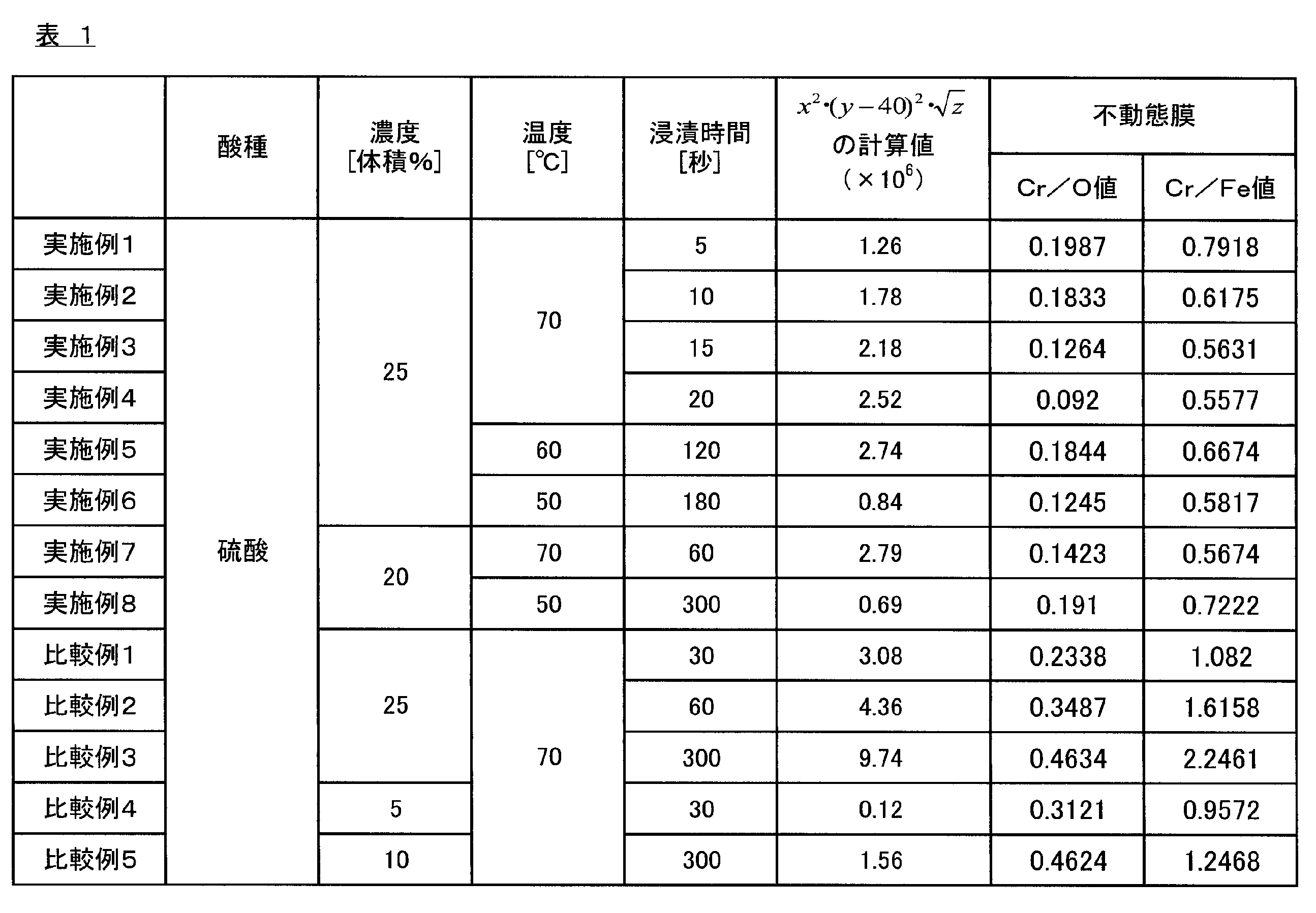
- Examples 2 to 8 A stainless steel plate 10 was prepared in the same manner as in Example 1 except that the concentration, temperature, and immersion time when the stainless steel material was immersed in the sulfuric acid aqueous solution were as shown in Table 1. Measurement of / O value and Cr / Fe value, XRD analysis, XPS measurement, measurement of surface roughness, cross-sectional observation, and measurement of electron beam diffraction pattern were performed. The results are shown in Table 1 and FIGS.
- FIG. 2 has shown the result of having measured the peak of Fe2p, Ni2p, Cr2p, O1s, respectively about the surface of the passive film 11 formed on the stainless steel plate 10 by XPS measurement.
- FIG. 2 (A) shows the results of measuring Fe2p
- FIG. 2 (B) shows the Ni2p
- FIG. 2 (C) shows the Cr2p
- FIG. 2 (D) shows the results of measuring the O1s peak.
- the result of Example 2 is indicated by a broken line
- the result of Comparative Example 2 described later is indicated by a dotted line
- Measurement results are indicated by solid lines.
- FIG. 5 is a graph showing the results of XRD analysis, in which the horizontal axis indicates the diffraction angle, and the vertical axis indicates the intensity of the diffracted X-ray detected by the X-ray diffractometer.
- the information about the crystal and crystal plane from which the peak originates is shown together in each peak portion.
- FeCrNiC is an FeCrNiC compound crystal
- CrOxide is a chromium oxide crystal
- Cr0.4Ni0.6 has a Cr: Ni ratio of 0.4: 0.6 (atomic%).
- the crystals of the CrNi alloy are shown respectively.
- FIG. 6 is a diagram showing a result of cross-sectional observation in the stainless steel plate 10 having the passive film 11 formed on the surface.
- 6A shows the results of Example 2
- FIG. 6B shows the results of Comparative Example 2 described later
- FIG. 6C shows the results of the stainless steel material (SUS316L) not immersed in the sulfuric acid aqueous solution.
- FIG. 7 shows the result of measuring the electron beam diffraction pattern for the surface of the passive film 11 formed on the stainless steel plate 10.
- 7A shows the result of Example 2
- FIG. 7B shows the result of Comparative Example 2 described later
- FIG. 7C shows the result of stainless steel (SUS316L) not immersed in the sulfuric acid aqueous solution.
- FIG. 7A shows the measurement result of the diffraction pattern from a crystal (element ratio: Fe 2.96 Cr 0.03 Ni 0.01 O 4 ) containing a relatively large amount of simple iron. Yes.
- FIG. 7B shows a measurement result of a diffraction pattern from a crystal (element ratio: Cr 0.19 Fe 0.7 Ni 0.11 ) containing a relatively large amount of nickel oxide.
- 7 (C) shows a measurement result of a diffraction pattern from a chromium oxide crystal (MnCr 2 O 4 ).
- Comparative Examples 1 to 5 A stainless steel plate 10 was prepared in the same manner as in Example 1 except that the concentration of the sulfuric acid aqueous solution and the immersion time when the stainless steel material was immersed in the sulfuric acid aqueous solution were as shown in Table 1, and according to the method described above. , Cr / O value and Cr / Fe value measurement, XRD analysis, XPS measurement, surface roughness measurement, cross-sectional observation, and electron diffraction pattern measurement were performed. The results are shown in Table 1 and FIGS.
- Comparative Examples 6 to 9 Instead of the treatment of immersing the stainless steel material in the sulfuric acid aqueous solution, the treatment was carried out except that the treatment of immersing the stainless steel material in hydrochloric acid was performed, and the hydrochloric acid concentration, temperature, and immersion time when immersed in hydrochloric acid were as shown in Table 2.
- a stainless steel plate 10 was prepared in the same manner as in Example 1, and the Cr / O value and the Cr / Fe value were measured according to the method described above. The results are shown in Table 2.
- Comparative Example 10 In place of the treatment of immersing the stainless steel material in the sulfuric acid aqueous solution, the stainless steel material is treated by immersing the stainless steel material in an acidic aqueous solution having a sulfuric acid concentration: 6% by volume and a phosphoric acid concentration: 4% by volume.
- a stainless steel plate 10 was produced in the same manner as in Example 1 except that the immersion time was as shown in Table 2, and the Cr / O value and the Cr / Fe value were measured according to the method described above. The results are shown in Table 2.
- Comparative Example 11 >> The stainless steel material (SUS316L) used in Example 1 was measured for Cr / O value and Cr / Fe value according to the method described above without being immersed in an aqueous sulfuric acid solution. The results are shown in Table 2 and FIG.
- the stainless steel plates 10 of Examples 2 and 3 and Comparative Examples 1 and 11 are subjected to electroless silver plating treatment on the passive film 11 of the stainless steel plate 10.
- the metal plating layer 20 a silver plating layer having a thickness of about 60 nm was formed to obtain a metal plating coated stainless steel material 100 (silver).
- the plating property of the silver plating layer was evaluated. Specifically, the surface of the metal plating coated stainless steel material 100 (silver) is measured with a fluorescent X-ray analyzer (manufactured by Rigaku Corporation, model number: ZSX100e) to determine the presence or absence of Ag, and when Ag is detected The plating property was evaluated by judging that the silver plating layer was well formed.
- a fluorescent X-ray analyzer manufactured by Rigaku Corporation, model number: ZSX100e
- the adhesion of the silver plating layer was evaluated for the metal plating coated stainless steel 100 (silver) obtained from the stainless steel plates 10 of Examples 2 and 3 and Comparative Example 1. Specifically, after affixing an adhesive tape (made by Nichiban Co., Ltd., Nystack strong type) to the silver plating layer of the metal plating coated stainless steel 100 (silver), a peeling test was carried out by peeling, and then the silver plating layer When the peeling state was observed, and peeling was not confirmed, the adhesion was evaluated by judging that the adhesion of the silver plating layer was good.
- an adhesive tape made by Nichiban Co., Ltd., Nystack strong type
- the Cr / O value by the Auger electron spectroscopic analysis on the surface is in the range of 0.05 to 0.2
- the Cr / Fe value is in the range of 0.5 to 0.8.
- the adhesion of the palladium plating layer was evaluated for the metal plating coated stainless steel material 100 (palladium) obtained from the stainless steel plate 10 of Examples 3 and 4. Specifically, an adhesive tape (manufactured by Nichiban Co., Ltd., Ny stack strong type) is applied to the palladium plating layer of the metal plating coated stainless steel 100 (palladium), and then peeled off, and then the palladium plating layer. When the peeling state was observed and no peeling was confirmed, the adhesion was evaluated by judging that the adhesion of the palladium plating layer was good.
- an adhesive tape manufactured by Nichiban Co., Ltd., Ny stack strong type
- the Cr / O value by the Auger electron spectroscopic analysis on the surface is in the range of 0.05 to 0.2
- the Cr / Fe value is in the range of 0.5 to 0.8.
- a platinum plating layer having a thickness of about 20 nm was formed as a metal plating layer 20 on the passive film 11 of the stainless steel plate 10 to obtain a metal plating coated stainless steel material 100 (platinum). . And about the obtained metal plating coating
- the metal plating coated stainless steel material 100 (platinum) obtained from the stainless steel plate 10 of Examples 3 and 4 was not confirmed in the peeling test using the adhesive tape, and the platinum plating layer was not adhered. It was confirmed that the property was good.
- the stainless steel plate 10 of the comparative example 11 since it was confirmed that the plating property of a platinum plating layer is inadequate, the adhesiveness evaluation of the platinum plating layer was not performed.
- the Cr / O value by the Auger electron spectroscopic analysis on the surface is in the range of 0.05 to 0.2
- the Cr / Fe value is in the range of 0.5 to 0.8.
- the platinum plating layer formed on the passive film 11 was excellent in plating properties and adhesion.
- cover stainless steel material similarly to the metal plating coating stainless steel material 100 (silver) mentioned above, metal plating coating stainless steel material 100 (palladium), and metal plating coating stainless steel material 100 (platinum), it is plating property. Evaluation and adhesion were evaluated.
- the gold-plated coated stainless steel materials obtained from the stainless steel plates 10 of Examples 1 to 8 and Comparative Examples 1 to 3 detected Au from the surface by measurement using a fluorescent X-ray analyzer, and the gold plate was excellent. It was confirmed that a plating layer was formed.
- the gold-plated coated stainless steel material obtained from the stainless steel plates 10 of Comparative Examples 4 to 11 did not detect Au from the surface, and it was confirmed that the plating property of the gold plating layer was insufficient.
- the gold-plated coated stainless steel materials obtained from the stainless steel plates 10 of Examples 1 to 8 showed no peeling of the gold plating layer in the peeling test using the adhesive tape, and the adhesion of the gold plating layer was good. It was confirmed that there was.
- the gold plating coated stainless steel materials obtained from the stainless steel plates 10 of Comparative Examples 1 to 3 a part or the whole of the gold plating layer was peeled off by the peel test, and the adhesion of the gold plating layer was insufficient. It was confirmed that there was.
- the stainless steel plates 10 of Comparative Examples 4 to 11 it was confirmed that the plating property of the gold plating layer was insufficient as described above, and thus the adhesion of the gold plating layer was not evaluated.
- the Cr / O value by the Auger electron spectroscopic analysis on the surface is in the range of 0.05 to 0.2
- the Cr / Fe value is in the range of 0.5 to 0.8.
- the gold plating layer formed on the passive film 11 was excellent in plating properties and adhesion.
- Comparative Examples 6 to 10 in which the sample was immersed in a solution other than the sulfuric acid aqueous solution, and Comparative Example 11 in which the immersion was not performed were the Cr / O value and Cr / Fe value obtained by Auger electron spectroscopy analysis on the surface of the formed passive film 11. It was confirmed that the value was out of the above range.
- FIG. 5 is a diffraction profile showing the results of XRD analysis using Example X and a stainless steel material (SUS316L) not immersed in an aqueous sulfuric acid solution using an X-ray diffractometer.
- the horizontal axis represents the diffraction angle and the vertical axis represents the diffraction intensity.
- the peaks of the diffraction profile shown in FIG. 5 are Cr0.4Ni0.6 crystal planes (1: 1), (20.0), (22.0), and CrOxide crystal planes (1.1.1).
- Example 3 in which the stainless steel material was immersed in the sulfuric acid aqueous solution, the diffraction angle derived from the crystal plane of CrOxide (2.20) was 66 ° as compared with SUS316L not immersed in the sulfuric acid aqueous solution. The nearby peak and the peak near the diffraction angle of 75 ° derived from the crystal plane of Cr0.4Ni0.6 (2.20) are small.
- Example 3 it is thought that Cr intensity
- Example 2 in which the concentration, temperature, and immersion time when the stainless steel material is immersed in the sulfuric acid aqueous solution satisfies the relationship of the above formula (1) is shown in FIG. From the graph, the peak of Fe (metal) in the vicinity of 707 eV is larger than that of SUS316L (untreated) that is not immersed in the sulfuric acid aqueous solution, which is active on the surface of the formed passive film 11. It can be confirmed that single iron (Fe (metal)) is exposed.
- Examples 1 to 4 in which the concentration, temperature, and immersion time when the stainless steel material is immersed in the sulfuric acid aqueous solution satisfy the relationship of the above formula (1) are immersed in the sulfuric acid aqueous solution.
- the arithmetic average roughness Ra is larger than before the immersion (immersion time 0 second), and thereby the plating property and adhesion of the metal plating layer 20 formed on the passive film 11 by the anchor effect. It was confirmed to be excellent.
- Example 2 in which the concentration, temperature, and immersion time when the stainless steel material is immersed in the sulfuric acid aqueous solution satisfies the relationship of the above formula (1) is SUS316L (untreated ), The crystal structure on the surface of the stainless steel material 10 was confirmed to have changed.
- Example 2 the surface shape of the stainless steel material 10 is roughened by the aqueous sulfuric acid solution as compared with SUS316L (untreated). .
- Example 2 as shown in FIG. 7A, a diffraction pattern from a crystal containing a relatively large amount of simple iron was measured, while SUS316L (untreated) was measured in FIG. 7C. As shown, diffraction from crystals of chromium oxide was measured. As a result, it was confirmed that in Example 2, the crystal structure on the surface of the stainless steel material 10 was changed as compared with SUS316L (untreated), and crystals containing a relatively large amount of simple iron were exposed.
- the stainless steel plate is eroded by the sulfuric acid aqueous solution, so that iron is preferentially eluted, Since the amount of Cr increases, the Cr / O value and the Cr / Fe value become too high.
- the concentration, temperature, and immersion time when the stainless steel material is immersed in the sulfuric acid aqueous solution do not satisfy the relationship of the above formula (1). It can be confirmed that the structure is fragile due to the corrosion of the ant nest.
- Comparative Example 2 as shown in FIG. 7B, a diffraction pattern from a crystal containing a relatively large amount of nickel oxide was measured, and the crystal structure on the surface of the stainless steel material 10 was changed. It can be confirmed that the proportion of nickel oxide having brittle properties is increased.
- Example 3 by forming a silver plating layer, a palladium plating layer, and a platinum plating layer as the metal plating layer 20 on the passive film 11 of the stainless steel plate 10, the above-described metal plating coated stainless steel 100 ( Silver), metal plating coated stainless steel 100 (palladium) and metal plating coated stainless steel 100 (platinum) were obtained. Then, the surfaces of the obtained metal plating coated stainless steel 100 (silver), metal plating coated stainless steel 100 (palladium), and metal plating coated stainless steel 100 (platinum) were respectively scanned with an electron microscope SEM (manufactured by Hitachi High-Technologies Corporation). S-4800) to obtain SEM photographs. The results are shown in FIG.
- FIG. 8A is an SEM photograph before forming the metal plating layer 20
- FIG. 8B is a metal plating coated stainless steel 100 (FIG. 8B) obtained by forming a silver plating layer as the metal plating layer 20.
- FIG. 8C is an SEM photograph of a metal plating coated stainless steel material 100 (palladium) obtained by forming a palladium plating layer as the metal plating layer 20, and FIG.
- the SEM photograph of the metal plating covering stainless steel material 100 (platinum) obtained by forming the platinum plating layer is shown.
- Example 3 in which the passive film 11 was formed, it was confirmed that the silver plating layer, the palladium plating layer, and the platinum plating layer formed as the metal plating layer 20 on the passivation film 11 were formed well. It was.
- a Cr / O value by the Auger electron spectroscopic analysis on the surface is 0.05 to 0.2 and the Cr / Fe value is in the range of 0.5 to 0.8.
- the metal plating coated stainless steel material 100 (platinum) obtained by forming a platinum plating layer as the metal plating layer 20 on the passive film 11 is a conventional fuel cell separator. Compared to SUS316L used as a material or the like, the contact resistance value was low, resulting in excellent conductivity.
- metal plating is shown.
- the metal constituting the layer 20 in addition to such silver (Ag), palladium (Pd) and platinum (Pt), rhodium (Rh), ruthenium (Ru), copper (Cu), tin (Sn) described above ) Or chromium (Cr).
- the metal plating layer 20 made of Ag, Pd, or Pt is excellent in plating properties and adhesion as described above. This is because Ag, Pd, and Pt are noble metals having a large standard electrode potential. This is because there is something. That is, since Ag, Pd and Pt are noble metals, they easily deposit on the passive film 11 of the stainless steel plate 10 by electroless plating, and the resulting metal plating layer 20 has a high coverage. As a result, the plating properties and adhesion of the metal plating layer 20 are excellent. Furthermore, since Ag, Pd and Pt are noble metals, they are excellent in that the contact resistance after aging hardly deteriorates. Further, the metal plating layer 20 made of Ag, Pd or Pt is excellent in conductivity as described above, which is due to the low contact resistance of Ag, Pd and Pt.
- any of the metals Rh, Ru, Cu, Sn and Cr described above is a noble metal having a large standard electrode potential and low contact resistance, like Ag, Pd and Pt. is doing. Therefore, even when a rhodium plating layer, a ruthenium plating layer, a copper plating layer, a tin plating layer, and a chromium plating layer are formed on the passive film 11 of the stainless steel plate 10 as the metal plating layer 20, the obtained metal plating layer is obtained.
- No. 20 is considered to be excellent in plating property, adhesion and conductivity, like the metal plating layer 20 made of Ag, Pd or Pt described above.
- metals other than Ag, Pd, Pt, Rh, Ru, Cu, Sn, and Cr described above are base metals having a relatively small standard electrode potential. It is difficult to deposit on the dynamic film 11, and the obtained metal plating layer 20 is considered to have poor plating properties and adhesion.
Landscapes
- Chemical & Material Sciences (AREA)
- Metallurgy (AREA)
- Chemical Kinetics & Catalysis (AREA)
- Engineering & Computer Science (AREA)
- Materials Engineering (AREA)
- Organic Chemistry (AREA)
- Mechanical Engineering (AREA)
- General Chemical & Material Sciences (AREA)
- Inorganic Chemistry (AREA)
- Electrochemistry (AREA)
- Other Surface Treatments For Metallic Materials (AREA)
- Chemical Treatment Of Metals (AREA)
- Electroplating Methods And Accessories (AREA)
- Fuel Cell (AREA)
Abstract
Description

本実施形態の金属めっき被覆ステンレス材100は、図1に示すように、不動態膜11が形成されたステンレス鋼板10上に、Ag、Pd、Pt、Rh、Ru、Cu、Sn、Crのうちいずれか一の金属またはこれらのうち少なくとも二以上の金属からなる合金により構成された金属めっき層20が形成されることで構成され、ステンレス鋼板10の不動態膜11は、表面におけるオージェ電子分光分析によるCr/O値が0.05~0.2、かつCr/Fe値が0.5~0.8の範囲であることを特徴とする。
本実施形態の金属めっき被覆ステンレス材100の基板となるステンレス鋼板10としては、特に限定されないが、SUS316、SUS316L、SUS304などのステンレス鋼材が挙げられる。また、ステンレス鋼板にはマルテンサイト系、フェライト系、オーステナイト系などの種類があるが、特にオーステナイト系ステンレス鋼板が好適である。ステンレス鋼板10の形状としては、特に限定されず、使用用途に応じて適宜選択することができるが、たとえば、線形状や板形状に加工された導電性の金属部品、板を凹凸形状に加工してなる導電性部材、ばね形状や筒形状に加工された電子機器の部品などの用途に応じて必要な形状に加工したもの用いることができる。また、ステンレス鋼板10の太さ(直径)や厚み(板厚)は、特に限定されず、使用用途に応じて適宜選択することができる。

金属めっき層20は、ステンレス鋼板10の不動態膜11上に、めっき処理を施すことにより形成される層である。なお、本実施形態においては、金属めっき層20を構成する金属としては、銀(Ag)、パラジウム(Pd)、白金(Pt)、ロジウム(Rh)、ルテニウム(Ru)、銅(Cu)、錫(Sn)、クロム(Cr)のうちいずれか一の金属、またはこれらのうち少なくとも二以上の金属からなる合金が挙げられ、これらのうち、Ag、PdまたはPtが特に好ましい。また、金属めっき層20を形成するめっき方法は特に限定されないが、Ag、Pd、Pt、Rh、Ru、Cu、Sn、Crなどの塩を含むめっき浴を用いて、無電解めっきにより形成することが好ましい。
なお、各特性の定義および評価方法は、以下のとおりである。
表面に不動態膜11を形成したステンレス鋼板10について、走査型オージェ電子分光分析装置(AES)(日本電子社製、型番:JAMP-9500F)を用いて、5箇所について、Cr、OおよびFeの原子%を測定し、得られた結果を平均することにより、Cr/O値(Crの原子%/Oの原子%)およびCr/Fe値(Crの原子%/Feの原子%)を求めた。なお、Cr/O値およびCr/Fe値の測定は、後述するすべての実施例および比較例について行った。
表面に不動態膜11を形成したステンレス鋼板10の表面を、X線回折装置(リガク社製、型番:RINT-2500)を用いて、ステンレス鋼板10の表面に含まれる結晶の同定を行った。なお、XRD分析は、後述する実施例および比較例のうち、実施例3についてのみ行った。また、比較のため、併せて、硫酸水溶液に浸漬させていないステンレス鋼材(SUS316L)についても、同様にXRD分析を行った。
ステンレス鋼板10上に形成した不動態膜11の表面について、X線光電子分光装置(アルバック・ファイ社製、型番:VersaProbeII)を用いて、Fe2p、Ni2p、Cr2p、O1sのピークをそれぞれ測定することにより、XPS測定を行った。なお、XPS測定は、後述する実施例および比較例のうち、実施例2、および比較例2についてのみ行った。また、比較のため、併せて、硫酸水溶液に浸漬させていないステンレス鋼材(SUS316L)についても、同様にXPS測定を行った。
ステンレス鋼板10上に形成した不動態膜11の表面について、レーザー顕微鏡(オリンパス社製、LEXT OLS3500)を用い、JIS B 0601:1994に準拠して算術平均粗さRaを測定した。なお、表面粗さの測定は、後述する実施例および比較例のうち、実施例1,2,4、および比較例1,2についてのみ行った。また、比較のため、併せて、硫酸水溶液に浸漬させていないステンレス鋼材(SUS316L)についても、同様に表面粗さの測定を行った。
表面に不動態膜11を形成したステンレス鋼板10について、炭素蒸着により炭素蒸着膜を形成した後で切断し、切断した断面を、走査型電子顕微鏡(日立ハイテクノロジーズ社製、型番:HD-2700)により測定することで断面写真を得た。なお、断面観察は、後述する実施例および比較例のうち、実施例2、および比較例2についてのみ行った。また、比較のため、併せて、硫酸水溶液に浸漬させていないステンレス鋼材(SUS316L)についても、同様に断面観察を行った。
ステンレス鋼板10上に形成した不動態膜11の表面について、透過型電子顕微鏡(日立ハイテクノロジーズ社製、型番:HF-2000)により測定することで、電子線回折パターンを得た。なお、電子線回折パターンの測定は、後述する実施例および比較例のうち、実施例2、および比較例2についてのみ行った。また、比較のため、併せて、硫酸水溶液に浸漬させていないステンレス鋼材(SUS316L)についても、同様に電子線回折パターンの測定を行った。
金属めっき被覆ステンレス材100について、図9に示すような測定系を用いて、接触抵抗値の測定を行った。なお、図9に示す測定系は、金属めっき被覆ステンレス材100、燃料電池用セパレータにおいてガス拡散層として用いられるカーボンクロス200、金めっき被覆された銅電極300、電圧計400、および電流計500によって構成される。接触抵抗値の測定は、具体的には、まず、金属めっき被覆ステンレス材100を幅20mm、長さ20mm、厚さ1.27mmの大きさに加工し、図9に示すように、カーボンクロス200(東レ社製、品番:TGP-H-090)を介して、金めっき被覆された銅電極300によって両側から挟んで固定することで、図9に示す測定系とした。次いで、金めっき被覆された銅電極300に10kg/cm2の荷重を加えながら、抵抗計(日置電機社製、ミリオームハイテスタ3540)を用いて、試験片を挟んだ上下のカーボンクロス200間の接触抵抗値を測定した。なお、接触抵抗値の測定は、後述する実施例および比較例のうち、実施例4についてのみ行った。また、比較として、併せて、硫酸水溶液に浸漬させていないステンレス鋼材(SUS316L)についても、幅20mm、長さ20mm、厚さ1.0mmの大きさに加工した後、同様に接触抵抗値の測定を行った。
まず、ステンレス鋼板10を形成するためのステンレス鋼材(SUS316L)を準備した。次いで、準備したステンレス鋼材を、硫酸濃度:25体積%の硫酸水溶液に、温度:70℃、浸漬時間:5秒の条件で浸漬させることにより、表面に不動態膜11が形成されたステンレス鋼板10を得た。
ステンレス鋼材を硫酸水溶液に浸漬させる際の濃度、温度、および浸漬時間を、表1に示すものとした以外は、実施例1と同様にしてステンレス鋼板10を作製し、上述した方法にしたがって、Cr/O値およびCr/Fe値の測定、XRD分析、XPS測定、表面粗さの測定、断面観察、電子線回折パターンの測定を行った。結果を表1、図2~7に示す。
ステンレス鋼材を硫酸水溶液に浸漬させる際における、硫酸水溶液の濃度、および浸漬時間を、表1に示すものとした以外は、実施例1と同様にしてステンレス鋼板10を作製し、上述した方法にしたがって、Cr/O値およびCr/Fe値の測定、XRD分析、XPS測定、表面粗さの測定、断面観察、電子線回折パターンの測定を行った。結果を表1、図2~4,6,7に示す。
ステンレス鋼材を硫酸水溶液に浸漬させる処理に代えて、ステンレス鋼材を塩酸に浸漬させる処理を行い、塩酸に浸漬させる際における塩酸濃度、温度、および浸漬時間を表2に示すものとした以外は、実施例1と同様にしてステンレス鋼板10を作製し、上述した方法にしたがって、Cr/O値およびCr/Fe値の測定を行った。結果を表2に示す。
ステンレス鋼材を硫酸水溶液に浸漬させる処理に代えて、ステンレス鋼材を硫酸濃度:6体積%、リン酸濃度:4体積%の酸性水溶液に浸漬させる処理を行い、この酸性水溶液に浸漬させる際における温度および浸漬時間を表2に示すものとした以外は、実施例1と同様にしてステンレス鋼板10を作製し、上述した方法にしたがって、Cr/O値およびCr/Fe値の測定を行った。結果を表2に示す。
実施例1で用いたステンレス鋼材(SUS316L)について、硫酸水溶液に浸漬させることなく、上述した方法にしたがって、Cr/O値およびCr/Fe値の測定を行った。結果を表2、図3に示す。

また、上述した実施例および比較例のうち、実施例2,3および比較例1,11のステンレス鋼板10について、無電解銀めっき処理を施すことにより、ステンレス鋼板10の不動態膜11上に、金属めっき層20として、厚さ約60nmの銀めっき層を形成し、金属めっき被覆ステンレス材100(銀)を得た。
また、上述した実施例および比較例のうち、実施例3,4および比較例11のステンレス鋼板10について、無電解パラジウムめっき浴(奥野製薬工業社製、品番:パラトップ)を用いて60℃、40秒の条件で無電解めっき処理を施すことにより、ステンレス鋼板10の不動態膜11上に、金属めっき層20として、厚さ約10nmのパラジウムめっき層を形成し、金属めっき被覆ステンレス材100(パラジウム)を得た。そして、得られた金属めっき被覆ステンレス材100(パラジウム)について、上述した金属めっき被覆ステンレス材100(銀)と同様に、めっき性の評価および密着性の評価を行った。
また、上述した実施例および比較例のうち、実施例3,4および比較例11のステンレス鋼板10について、ステンレス鋼板10の不動態膜11上に白金めっき層を形成し、白金めっき層のめっき性および密着性を評価した。具体的には、実施例3,4および比較例11のステンレス鋼板10について、無電解白金めっき浴(日本高純度化学社製、品番:IM-Pt)を用いて55℃、3分の条件で無電解めっき処理を施すことにより、ステンレス鋼板10の不動態膜11上に、金属めっき層20として、厚さ約20nmの白金めっき層を形成し、金属めっき被覆ステンレス材100(白金)を得た。そして、得られた金属めっき被覆ステンレス材100(白金)について、上述した金属めっき被覆ステンレス材100(銀)および金属めっき被覆ステンレス材100(パラジウム)と同様に、めっき性の評価および密着性の評価を行った。
さらに、実施例1~8および比較例1~11について、ステンレス鋼板10の不動態膜11上に金めっき層を形成し、金めっき層のめっき性および密着性を評価した。具体的には、実施例1~8および比較例1~11のステンレス鋼板10について、無電解金めっき浴(奥野製薬工業社製、品番:フラッシュゴールドNF)を用いて、70℃、5分間の条件で無電解めっき処理を施すことにより、不動態膜11上に、厚さ約23nmの金めっき層を形成し、金めっき被覆ステンレス材を得た。そして、得られた金めっき被覆ステンレス材について、上述した金属めっき被覆ステンレス材100(銀)、金属めっき被覆ステンレス材100(パラジウム)および金属めっき被覆ステンレス材100(白金)と同様に、めっき性の評価および密着性の評価を行った。
Claims (4)
- 表面におけるオージェ電子分光分析によるCr/O値が0.05~0.2、かつCr/Fe値が0.5~0.8の範囲である不動態膜が形成されたステンレス鋼板と、
前記ステンレス鋼板の不動態膜上に形成された、Ag、Pd、Pt、Rh、Ru、Cu、Sn、Crのうちいずれか一の金属またはこれらのうち少なくとも二以上の金属からなる合金により構成された金属めっき層と、を備えることを特徴とする金属めっき被覆ステンレス材。 - 前記金属めっき層の被覆率が95%以上であることを特徴とする請求項1に記載の金属めっき被覆ステンレス材。
- ステンレス鋼板を、硫酸水溶液に浸漬させる浸漬工程と、
前記ステンレス鋼板上に、Ag、Pd、Pt、Rh、Ru、Cu、Sn、Crのうちいずれか一の金属またはこれらのうち少なくとも二以上の金属からなる合金により構成された金属めっき層を形成するめっき工程と、を有する金属めっき被覆ステンレス材の製造方法であって、
前記浸漬工程において、ステンレス鋼板を硫酸水溶液に浸漬させる際の硫酸濃度をx[体積%](ただし、20≦x≦25)、温度をy[℃]、浸漬時間をz[秒]とした場合に、下記式(1)を満たすことを特徴とする金属めっき被覆ステンレス材の製造方法。
- ステンレス鋼板を、硫酸水溶液に浸漬させることで、前記ステンレス鋼板上に、表面におけるオージェ電子分光分析によるCr/O値が0.05~0.2、かつCr/Fe値が0.5~0.8の範囲となる不動態膜を形成する浸漬工程と、
前記ステンレス鋼板の不動態膜上に、Ag、Pd、Pt、Rh、Ru、Cu、Sn、Crのうちいずれか一の金属またはこれらのうち少なくとも二以上の金属からなる合金により構成された金属めっき層を形成するめっき工程と、を有することを特徴とする金属めっき被覆ステンレス材の製造方法。
Priority Applications (6)
| Application Number | Priority Date | Filing Date | Title |
|---|---|---|---|
| US15/023,323 US10294568B2 (en) | 2013-09-20 | 2014-09-11 | Metal plate coated stainless material and method of producing metal plate coated stainless material |
| CN201480051793.8A CN105556002B (zh) | 2013-09-20 | 2014-09-11 | 镀金属覆盖不锈钢材料以及镀金属覆盖不锈钢材料的制造方法 |
| JP2015537885A JP6495172B2 (ja) | 2013-09-20 | 2014-09-11 | 金属めっき被覆ステンレス材、および金属めっき被覆ステンレス材の製造方法 |
| EP14846487.8A EP3048186B1 (en) | 2013-09-20 | 2014-09-11 | Metal-plated stainless steel material, and production method for metal-plated stainless steel material |
| KR1020167006936A KR20160058795A (ko) | 2013-09-20 | 2014-09-11 | 금속 도금 피복 스텐레스재, 및 금속 도금 피복 스텐레스재의 제조 방법 |
| CA2924778A CA2924778A1 (en) | 2013-09-20 | 2014-09-11 | Metal plate coated stainless material and method of producing metal plate coated stainless material |
Applications Claiming Priority (4)
| Application Number | Priority Date | Filing Date | Title |
|---|---|---|---|
| JP2013195801 | 2013-09-20 | ||
| JP2013195796 | 2013-09-20 | ||
| JP2013-195801 | 2013-09-20 | ||
| JP2013-195796 | 2013-09-20 |
Publications (1)
| Publication Number | Publication Date |
|---|---|
| WO2015041132A1 true WO2015041132A1 (ja) | 2015-03-26 |
Family
ID=52688782
Family Applications (1)
| Application Number | Title | Priority Date | Filing Date |
|---|---|---|---|
| PCT/JP2014/074053 Ceased WO2015041132A1 (ja) | 2013-09-20 | 2014-09-11 | 金属めっき被覆ステンレス材、および金属めっき被覆ステンレス材の製造方法 |
Country Status (7)
| Country | Link |
|---|---|
| US (1) | US10294568B2 (ja) |
| EP (1) | EP3048186B1 (ja) |
| JP (1) | JP6495172B2 (ja) |
| KR (1) | KR20160058795A (ja) |
| CN (1) | CN105556002B (ja) |
| CA (1) | CA2924778A1 (ja) |
| WO (1) | WO2015041132A1 (ja) |
Cited By (6)
| Publication number | Priority date | Publication date | Assignee | Title |
|---|---|---|---|---|
| CN105500816A (zh) * | 2016-01-26 | 2016-04-20 | 大连诚通工程技术有限公司 | 一种胶粘式双金属复合板 |
| WO2016093145A1 (ja) * | 2014-12-12 | 2016-06-16 | 東洋鋼鈑株式会社 | 金属めっき被覆ステンレス材の製造方法 |
| WO2018135655A1 (ja) * | 2017-01-23 | 2018-07-26 | 日東電工株式会社 | 配線回路基板およびその製造方法 |
| JPWO2020261564A1 (ja) * | 2019-06-28 | 2020-12-30 | ||
| WO2020261563A1 (ja) * | 2019-06-28 | 2020-12-30 | 住友電気工業株式会社 | 銅被覆鋼線、撚線、絶縁電線およびケーブル |
| JPWO2021001928A1 (ja) * | 2019-07-02 | 2021-01-07 |
Families Citing this family (13)
| Publication number | Priority date | Publication date | Assignee | Title |
|---|---|---|---|---|
| KR102073454B1 (ko) * | 2013-06-13 | 2020-02-04 | 도요 고한 가부시키가이샤 | 금도금 피복 스테인리스재 및 금도금 피복 스테인리스재의 제조 방법 |
| US10998657B2 (en) | 2016-03-18 | 2021-05-04 | Apple Inc. | Precious-metal-alloy contacts |
| DE202017001425U1 (de) | 2016-03-18 | 2017-07-06 | Apple Inc. | Kontakte aus Edelmetallegierungen |
| CN108076608A (zh) * | 2016-11-14 | 2018-05-25 | 华为机器有限公司 | 金属机壳及其制造方法 |
| US20190103693A1 (en) * | 2017-09-29 | 2019-04-04 | Apple Inc. | Electrical contacts having sacrificial layer for corrosion protection |
| US11365658B2 (en) | 2017-10-05 | 2022-06-21 | Tenneco Automotive Operating Company Inc. | Acoustically tuned muffler |
| DE102018124198A1 (de) | 2017-10-05 | 2019-04-11 | Tenneco Automotive Operating Company Inc. | Akustisch abgestimmter Schalldämpfer |
| US11199116B2 (en) | 2017-12-13 | 2021-12-14 | Tenneco Automotive Operating Company Inc. | Acoustically tuned muffler |
| US11268430B2 (en) | 2019-01-17 | 2022-03-08 | Tenneco Automotive Operating Company Inc. | Diffusion surface alloyed metal exhaust component with welded edges |
| US11268429B2 (en) | 2019-01-17 | 2022-03-08 | Tenneco Automotive Operating Company Inc. | Diffusion surface alloyed metal exhaust component with inwardly turned edges |
| US10975743B1 (en) | 2020-03-13 | 2021-04-13 | Tenneco Automotive Operating Company Inc. | Vehicle exhaust component |
| KR102472734B1 (ko) | 2020-08-27 | 2022-12-01 | 삼원동관 주식회사 | 접합용 스테인리스강 파이프 |
| US12594174B1 (en) * | 2022-03-21 | 2026-04-07 | Professional Plating Inc. | Microminiature patterned metal on flexing interventional surgical substrates |
Citations (7)
| Publication number | Priority date | Publication date | Assignee | Title |
|---|---|---|---|---|
| JPS63282292A (ja) * | 1987-05-13 | 1988-11-18 | Nisshin Steel Co Ltd | ステンレス鋼板に直接めっきする方法 |
| JPH09217166A (ja) * | 1987-10-24 | 1997-08-19 | Tadahiro Omi | ステンレス鋼及びその製造方法並びに減圧装置 |
| JP2001011655A (ja) * | 1999-06-28 | 2001-01-16 | Daido Steel Co Ltd | メッキ付ステンレス鋼線材の製造方法及び装置 |
| JP2002124267A (ja) * | 2000-10-16 | 2002-04-26 | Toyota Motor Corp | 高分子電解質型燃料電池用セパレータの製造方法 |
| JP2008004498A (ja) | 2006-06-26 | 2008-01-10 | Mitsubishi Materials Corp | 酸化性環境下に長期間さらされても接触抵抗が増加することの少ない複合層被覆金属板 |
| JP2010138487A (ja) * | 2008-10-07 | 2010-06-24 | Sumitomo Metal Ind Ltd | 固体高分子型燃料電池のセパレータ用ステンレス鋼板およびそれを用いた固体高分子型燃料電池 |
| JP2010236091A (ja) * | 2002-08-20 | 2010-10-21 | Daido Steel Co Ltd | 耐食性導電部材とその製造方法及び燃料電池 |
Family Cites Families (6)
| Publication number | Priority date | Publication date | Assignee | Title |
|---|---|---|---|---|
| US5275696A (en) | 1993-05-03 | 1994-01-04 | The United States Of America As Represented By The Secretary Of The Navy | Stainless steel surface treatment |
| US20050142416A1 (en) * | 2003-12-24 | 2005-06-30 | Honda Motor Co., Ltd. | Fuel cell |
| BRPI0921570A2 (pt) * | 2008-11-25 | 2019-09-24 | Nissan Motor | membro condutor de eletricidade e célula de combustível de eletrólito de polímero utilizando o mesmo |
| JP5581805B2 (ja) * | 2010-05-24 | 2014-09-03 | トヨタ自動車株式会社 | ステンレス鋼材へのめっき方法及びそのめっき材 |
| KR102073454B1 (ko) | 2013-06-13 | 2020-02-04 | 도요 고한 가부시키가이샤 | 금도금 피복 스테인리스재 및 금도금 피복 스테인리스재의 제조 방법 |
| CA2928616A1 (en) * | 2013-10-28 | 2015-05-07 | Toyo Kohan Co., Ltd. | Alloy plate coated material and method of producing alloy plate coated material |
-
2014
- 2014-09-11 KR KR1020167006936A patent/KR20160058795A/ko not_active Abandoned
- 2014-09-11 JP JP2015537885A patent/JP6495172B2/ja active Active
- 2014-09-11 CA CA2924778A patent/CA2924778A1/en not_active Abandoned
- 2014-09-11 WO PCT/JP2014/074053 patent/WO2015041132A1/ja not_active Ceased
- 2014-09-11 CN CN201480051793.8A patent/CN105556002B/zh active Active
- 2014-09-11 US US15/023,323 patent/US10294568B2/en active Active
- 2014-09-11 EP EP14846487.8A patent/EP3048186B1/en not_active Not-in-force
Patent Citations (7)
| Publication number | Priority date | Publication date | Assignee | Title |
|---|---|---|---|---|
| JPS63282292A (ja) * | 1987-05-13 | 1988-11-18 | Nisshin Steel Co Ltd | ステンレス鋼板に直接めっきする方法 |
| JPH09217166A (ja) * | 1987-10-24 | 1997-08-19 | Tadahiro Omi | ステンレス鋼及びその製造方法並びに減圧装置 |
| JP2001011655A (ja) * | 1999-06-28 | 2001-01-16 | Daido Steel Co Ltd | メッキ付ステンレス鋼線材の製造方法及び装置 |
| JP2002124267A (ja) * | 2000-10-16 | 2002-04-26 | Toyota Motor Corp | 高分子電解質型燃料電池用セパレータの製造方法 |
| JP2010236091A (ja) * | 2002-08-20 | 2010-10-21 | Daido Steel Co Ltd | 耐食性導電部材とその製造方法及び燃料電池 |
| JP2008004498A (ja) | 2006-06-26 | 2008-01-10 | Mitsubishi Materials Corp | 酸化性環境下に長期間さらされても接触抵抗が増加することの少ない複合層被覆金属板 |
| JP2010138487A (ja) * | 2008-10-07 | 2010-06-24 | Sumitomo Metal Ind Ltd | 固体高分子型燃料電池のセパレータ用ステンレス鋼板およびそれを用いた固体高分子型燃料電池 |
Non-Patent Citations (2)
| Title |
|---|
| JIS B 0601, 1994 |
| See also references of EP3048186A4 |
Cited By (21)
| Publication number | Priority date | Publication date | Assignee | Title |
|---|---|---|---|---|
| WO2016093145A1 (ja) * | 2014-12-12 | 2016-06-16 | 東洋鋼鈑株式会社 | 金属めっき被覆ステンレス材の製造方法 |
| US10287689B2 (en) | 2014-12-12 | 2019-05-14 | Toyo Kohan Co., Ltd. | Method for producing metal-plated stainless material |
| CN105500816A (zh) * | 2016-01-26 | 2016-04-20 | 大连诚通工程技术有限公司 | 一种胶粘式双金属复合板 |
| WO2018135655A1 (ja) * | 2017-01-23 | 2018-07-26 | 日東電工株式会社 | 配線回路基板およびその製造方法 |
| JPWO2018135655A1 (ja) * | 2017-01-23 | 2019-11-07 | 日東電工株式会社 | 配線回路基板およびその製造方法 |
| US10808329B2 (en) | 2017-01-23 | 2020-10-20 | Nitto Denko Corporation | Wired circuit board and production method thereof |
| WO2020261563A1 (ja) * | 2019-06-28 | 2020-12-30 | 住友電気工業株式会社 | 銅被覆鋼線、撚線、絶縁電線およびケーブル |
| WO2020261564A1 (ja) * | 2019-06-28 | 2020-12-30 | 住友電気工業株式会社 | 銅被覆鋼線、ばね、撚線、絶縁電線およびケーブル |
| CN113994439B (zh) * | 2019-06-28 | 2024-05-24 | 住友电气工业株式会社 | 铜覆钢线、弹簧、绞合线、绝缘电线以及电缆 |
| JPWO2020261563A1 (ja) * | 2019-06-28 | 2020-12-30 | ||
| JPWO2020261564A1 (ja) * | 2019-06-28 | 2020-12-30 | ||
| US12614646B2 (en) | 2019-06-28 | 2026-04-28 | Sumitomo Electric Industries, Ltd. | Copper-coated steel wire, stranded wire, insulated electric wire, and cable |
| CN113994439A (zh) * | 2019-06-28 | 2022-01-28 | 住友电气工业株式会社 | 铜覆钢线、弹簧、绞合线、绝缘电线以及电缆 |
| JP7180774B2 (ja) | 2019-06-28 | 2022-11-30 | 住友電気工業株式会社 | 銅被覆鋼線、撚線、絶縁電線およびケーブル |
| JP7259958B2 (ja) | 2019-06-28 | 2023-04-18 | 住友電気工業株式会社 | 銅被覆鋼線、ばね、撚線、絶縁電線およびケーブル |
| US12224079B2 (en) | 2019-06-28 | 2025-02-11 | Sumitomo Electric Industries, Ltd. | Copper-coated steel wire, spring, stranded wire, insulated electric wire, and cable |
| CN113966539B (zh) * | 2019-06-28 | 2024-05-14 | 住友电气工业株式会社 | 铜覆钢线、绞合线、绝缘电线以及电缆 |
| JPWO2021001928A1 (ja) * | 2019-07-02 | 2021-01-07 | ||
| JP7259959B2 (ja) | 2019-07-02 | 2023-04-18 | 住友電気工業株式会社 | 銅被覆鋼線、撚線、絶縁電線およびケーブル |
| US12283390B2 (en) | 2019-07-02 | 2025-04-22 | Sumitomo Electric Industries, Ltd. | Copper-coated steel wire, stranded wire, insulated electric wire, and cable |
| WO2021001928A1 (ja) * | 2019-07-02 | 2021-01-07 | 住友電気工業株式会社 | 銅被覆鋼線、撚線、絶縁電線およびケーブル |
Also Published As
| Publication number | Publication date |
|---|---|
| JPWO2015041132A1 (ja) | 2017-03-02 |
| CN105556002A (zh) | 2016-05-04 |
| US10294568B2 (en) | 2019-05-21 |
| US20160340786A1 (en) | 2016-11-24 |
| CN105556002B (zh) | 2018-03-20 |
| KR20160058795A (ko) | 2016-05-25 |
| JP6495172B2 (ja) | 2019-04-03 |
| CA2924778A1 (en) | 2015-03-26 |
| EP3048186B1 (en) | 2018-07-04 |
| EP3048186A4 (en) | 2017-05-31 |
| EP3048186A1 (en) | 2016-07-27 |
Similar Documents
| Publication | Publication Date | Title |
|---|---|---|
| JP6495172B2 (ja) | 金属めっき被覆ステンレス材、および金属めっき被覆ステンレス材の製造方法 | |
| CN105309061B (zh) | 电磁波屏蔽用金属箔、电磁波屏蔽材和屏蔽电缆 | |
| JP6220393B2 (ja) | 金めっき被覆ステンレス材、および金めっき被覆ステンレス材の製造方法 | |
| JP6706067B2 (ja) | 合金めっき被覆材料、および合金めっき被覆材料の製造方法 | |
| US10006125B2 (en) | Gold plate coated material | |
| JP2013227630A (ja) | コネクタ用めっき端子 | |
| WO2016093145A1 (ja) | 金属めっき被覆ステンレス材の製造方法 | |
| CN107851811B (zh) | 燃料电池用通电构件、燃料电池单元、燃料电池堆和燃料电池用通电构件的制造方法 | |
| WO2018212174A1 (ja) | 錫めっき付銅端子材及び端子並びに電線端末部構造 | |
| JP6199086B2 (ja) | パラジウムめっき被覆材料、およびパラジウムめっき被覆材料の製造方法 | |
| JP6628585B2 (ja) | 金属めっき被覆ステンレス材の製造方法 | |
| JP6574568B2 (ja) | 金属めっき被覆ステンレス材の製造方法 | |
| US10629917B2 (en) | Separator for fuel cells, fuel cell, fuel cell stack, and method of manufacturing separator for fuel cells | |
| JP6848022B2 (ja) | 金属めっき被覆ステンレス材の製造方法 | |
| JP2009084590A (ja) | 金属めっきステンレス鋼板材の製造方法 |
Legal Events
| Date | Code | Title | Description |
|---|---|---|---|
| WWE | Wipo information: entry into national phase |
Ref document number: 201480051793.8 Country of ref document: CN |
|
| 121 | Ep: the epo has been informed by wipo that ep was designated in this application |
Ref document number: 14846487 Country of ref document: EP Kind code of ref document: A1 |
|
| ENP | Entry into the national phase |
Ref document number: 2015537885 Country of ref document: JP Kind code of ref document: A |
|
| ENP | Entry into the national phase |
Ref document number: 20167006936 Country of ref document: KR Kind code of ref document: A |
|
| ENP | Entry into the national phase |
Ref document number: 2924778 Country of ref document: CA |
|
| REEP | Request for entry into the european phase |
Ref document number: 2014846487 Country of ref document: EP |
|
| WWE | Wipo information: entry into national phase |
Ref document number: 2014846487 Country of ref document: EP |
|
| NENP | Non-entry into the national phase |
Ref country code: DE |
|
| WWE | Wipo information: entry into national phase |
Ref document number: 15023323 Country of ref document: US |