WO2015072565A1 - 非接触給電システム - Google Patents
非接触給電システム Download PDFInfo
- Publication number
- WO2015072565A1 WO2015072565A1 PCT/JP2014/080348 JP2014080348W WO2015072565A1 WO 2015072565 A1 WO2015072565 A1 WO 2015072565A1 JP 2014080348 W JP2014080348 W JP 2014080348W WO 2015072565 A1 WO2015072565 A1 WO 2015072565A1
- Authority
- WO
- WIPO (PCT)
- Prior art keywords
- cover
- power
- coil
- power feeding
- foreign matter
- Prior art date
- Legal status (The legal status is an assumption and is not a legal conclusion. Google has not performed a legal analysis and makes no representation as to the accuracy of the status listed.)
- Ceased
Links
Images




Classifications
-
- H—ELECTRICITY
- H02—GENERATION; CONVERSION OR DISTRIBUTION OF ELECTRIC POWER
- H02J—ELECTRIC POWER NETWORKS; CIRCUIT ARRANGEMENTS OR SYSTEMS FOR SUPPLYING OR DISTRIBUTING ELECTRIC POWER; SYSTEMS FOR STORING ELECTRIC ENERGY
- H02J50/00—Circuit arrangements or systems for wireless supply or distribution of electric power
- H02J50/10—Circuit arrangements or systems for wireless supply or distribution of electric power using inductive coupling
- H02J50/12—Circuit arrangements or systems for wireless supply or distribution of electric power using inductive coupling of the resonant type
-
- B—PERFORMING OPERATIONS; TRANSPORTING
- B60—VEHICLES IN GENERAL
- B60L—PROPULSION OF ELECTRICALLY-PROPELLED VEHICLES; SUPPLYING ELECTRIC POWER FOR AUXILIARY EQUIPMENT OF ELECTRICALLY-PROPELLED VEHICLES; ELECTRODYNAMIC BRAKE SYSTEMS FOR VEHICLES IN GENERAL; MAGNETIC SUSPENSION OR LEVITATION FOR VEHICLES; MONITORING OPERATING VARIABLES OF ELECTRICALLY-PROPELLED VEHICLES; ELECTRIC SAFETY DEVICES FOR ELECTRICALLY-PROPELLED VEHICLES
- B60L53/00—Methods of charging batteries, specially adapted for electric vehicles; Charging stations or on-board charging equipment therefor; Exchange of energy storage elements in electric vehicles
- B60L53/10—Methods of charging batteries, specially adapted for electric vehicles; Charging stations or on-board charging equipment therefor; Exchange of energy storage elements in electric vehicles characterised by the energy transfer between the charging station and the vehicle
- B60L53/12—Inductive energy transfer
- B60L53/122—Circuits or methods for driving the primary coil, e.g. supplying electric power to the coil
-
- B—PERFORMING OPERATIONS; TRANSPORTING
- B60—VEHICLES IN GENERAL
- B60L—PROPULSION OF ELECTRICALLY-PROPELLED VEHICLES; SUPPLYING ELECTRIC POWER FOR AUXILIARY EQUIPMENT OF ELECTRICALLY-PROPELLED VEHICLES; ELECTRODYNAMIC BRAKE SYSTEMS FOR VEHICLES IN GENERAL; MAGNETIC SUSPENSION OR LEVITATION FOR VEHICLES; MONITORING OPERATING VARIABLES OF ELECTRICALLY-PROPELLED VEHICLES; ELECTRIC SAFETY DEVICES FOR ELECTRICALLY-PROPELLED VEHICLES
- B60L53/00—Methods of charging batteries, specially adapted for electric vehicles; Charging stations or on-board charging equipment therefor; Exchange of energy storage elements in electric vehicles
- B60L53/10—Methods of charging batteries, specially adapted for electric vehicles; Charging stations or on-board charging equipment therefor; Exchange of energy storage elements in electric vehicles characterised by the energy transfer between the charging station and the vehicle
- B60L53/12—Inductive energy transfer
- B60L53/124—Detection or removal of foreign bodies
-
- B—PERFORMING OPERATIONS; TRANSPORTING
- B60—VEHICLES IN GENERAL
- B60L—PROPULSION OF ELECTRICALLY-PROPELLED VEHICLES; SUPPLYING ELECTRIC POWER FOR AUXILIARY EQUIPMENT OF ELECTRICALLY-PROPELLED VEHICLES; ELECTRODYNAMIC BRAKE SYSTEMS FOR VEHICLES IN GENERAL; MAGNETIC SUSPENSION OR LEVITATION FOR VEHICLES; MONITORING OPERATING VARIABLES OF ELECTRICALLY-PROPELLED VEHICLES; ELECTRIC SAFETY DEVICES FOR ELECTRICALLY-PROPELLED VEHICLES
- B60L53/00—Methods of charging batteries, specially adapted for electric vehicles; Charging stations or on-board charging equipment therefor; Exchange of energy storage elements in electric vehicles
- B60L53/10—Methods of charging batteries, specially adapted for electric vehicles; Charging stations or on-board charging equipment therefor; Exchange of energy storage elements in electric vehicles characterised by the energy transfer between the charging station and the vehicle
- B60L53/12—Inductive energy transfer
- B60L53/126—Methods for pairing a vehicle and a charging station, e.g. establishing a one-to-one relation between a wireless power transmitter and a wireless power receiver
-
- H—ELECTRICITY
- H02—GENERATION; CONVERSION OR DISTRIBUTION OF ELECTRIC POWER
- H02J—ELECTRIC POWER NETWORKS; CIRCUIT ARRANGEMENTS OR SYSTEMS FOR SUPPLYING OR DISTRIBUTING ELECTRIC POWER; SYSTEMS FOR STORING ELECTRIC ENERGY
- H02J50/00—Circuit arrangements or systems for wireless supply or distribution of electric power
- H02J50/60—Circuit arrangements or systems for wireless supply or distribution of electric power responsive to the presence of foreign objects, e.g. detection of living beings
Definitions
- the present invention relates to a non-contact power feeding system.
- This application has priority based on Japanese Patent Application No. 2013-237918 filed in Japan on November 18, 2013 and Japanese Patent Application No. 2014-004642 filed in Japan on January 14, 2014. Insist and use that content here.
- a non-contact power feeding system that feeds power by making a power feeding coil and a power receiving coil face each other in a non-contact manner. That is, in recent years, a coil on the power feeding side (power feeding coil) is installed on the ground or buried so as to be flush with the ground, and an electric vehicle equipped with a coil on the power receiving side (power receiving coil) is stopped on the power feeding coil.
- a non-contact power feeding system that supplies power from a power feeding coil to a power receiving coil in a non-contact manner.
- the non-contact power supply system employs a magnetic field resonance method or an electromagnetic induction method, and is expected to be applied to power supply of a moving vehicle such as an electric vehicle.
- Patent Document 1 discloses a power supply device that includes a power transmission unit that performs power transmission using a magnetic field and a foreign matter exclusion operation unit that eliminates foreign matter in the vicinity of a power transmission path during power transmission.
- the foreign matter removing operation unit removes foreign matter by at least one operation of tilting, rotating, and vibrating the housing unit that houses the power transmission unit.
- Patent Document 2 discloses an electric vehicle including a sweeping unit that sweeps out foreign matter already present on a power feeding coil before the start of charging.
- the sweep unit is disposed on the bottom surface of the electric vehicle and is movable between the housed state and the sweepable state, and moves to the sweepable state when the electric vehicle approaches the power feeding unit.
- Patent Document 3 discloses an electric system including a dome-shaped housing that prevents animals and foreign objects from being placed on a ground equipment transducer.
- the dome-shaped housing includes an outer surface having a plurality of points arranged at a plurality of heights, at least one of the plurality of points having a first height, and the other points of the plurality of points are Each height is lower than the first height.
- Patent Document 4 discloses a charging device in which a charging surface is an inclined surface or a vertical surface having an angle with respect to a horizontal plane and prevents heat generation due to foreign matter.
- Patent Document 5 at least one of the power feeding coil and the power receiving coil is covered with a windable roll screen that can be opened and closed, and the surface (operation surface) of the power feeding coil and the power receiving coil is prevented from becoming dirty.
- a contact power supply system is disclosed.
- Patent Document 6 when performing non-contact power feeding, a foreign matter that is formed on a convex conical member that covers the power feeding coil and that is formed so as to move upward and come into close contact with the member that covers the power receiving coil, A non-contact power supply system is disclosed that falls along a conical slope as the power supply coil moves.
- Patent Document 7 when the presence of a foreign object on the power supply surface is detected during non-contact power supply, a current having a specific frequency is supplied to one of the two power supply coils, and two different frequencies are supplied from the two power supply coils.
- a contactless power supply system is disclosed in which two different magnetic fields are generated by the current of the current, and as a result, the power supply surface vibrates at a third frequency.
- Patent Document 8 discloses an apparatus that drives a brush by bending a polymer actuator alternately left and right to clean a lens and a CCD.
- Patent Document 9 discloses a paper transport device with a foreign matter adhesion preventing function that vibrates a transport roller by a giant magnetostrictive element and an image forming apparatus including the paper transport device.
- Patent Documents 1 and 3 Since the techniques of Patent Documents 1 and 3 are designed to incline the accommodating part that accommodates the power transmission part, it is not possible to increase the inclination in a narrow space between the electric vehicle and the ground, and some foreign objects are excluded. It may become insufficient. In addition, for example, when the foreign matter is a gum with silver paper and has adhesiveness, the foreign matter cannot be excluded by any of inclination, rotation, and vibration. In the technique of Patent Document 2, a sweeping unit must be mounted on an electric vehicle, and an apparatus needs to be added to the electric vehicle itself.
- an object of the present invention is to provide a non-contact power feeding system capable of reliably removing a placed foreign object from between a power feeding coil and a power receiving coil.
- a non-contact power feeding system that feeds power by making a power feeding coil and a power receiving coil face each other in a non-contact manner, on a facing surface of at least one of the power feeding coil and the power receiving coil.
- a cover that is slidable between a closed position to be covered and an open position that is retracted from the facing surface, and a foreign object that causes the foreign matter placed on the cover to accompany the slide of the cover from the closed position to the open position.
- accompanying means In the first aspect of the present invention, the surface on the opposite side of the power feeding coil or the power receiving coil is covered with a cover, and the foreign matter placed on the cover is caused to accompany the slide of the cover by the foreign matter accompanying means.
- the foreign matter is retreated from the facing surface together with the cover without causing the foreign matter to fall off the cover due to an inclination or the like, so the uncertainty of foreign matter removal can be eliminated.
- the foreign object accompanying means includes a hook member that is provided on the cover and protrudes upward from a placement surface on which the foreign object is placed.
- the cover is provided with a hook member, and the foreign matter placed on the placement surface of the cover is hooked on the hook member, so that the foreign matter can accompany the slide of the cover.
- a winding unit that winds the cover into a roll shape.
- by winding the cover in a roll shape it is not necessary to secure a large space at the slide destination of the cover, and space saving can be achieved.
- a folding means for folding the cover in a bellows shape in the first or second aspect, there is provided a folding means for folding the cover in a bellows shape.
- a folding means for folding the cover in a bellows shape by folding the cover in a bellows shape, it is not necessary to secure a large space at the slide destination of the cover, and space saving can be achieved.
- the foreign matter accompanying means has an attaching means for attaching the foreign matter to the cover.
- the adhering means is provided on the cover, and the adhering means adheres to the cover with the adhering means, so that the foreign substance can accompany the cover slide.
- the blade member scrapes off the foreign matter adhering to the cover at the destination of the foreign matter.
- a foreign matter collecting means for collecting the foreign matter at the destination of the foreign matter.
- the foreign matter collecting means by collecting the foreign matter placed on the cover by the foreign matter collecting means, the foreign matter can be prevented from returning to the opposing surface again.
- a power supply coil that performs power transmission in a contactless manner with respect to a moving body, a cover that covers the power supply coil, and a magnetic flux generated in the power supply coil that vibrates and vibrates the cover. And a vibration part connected to the cover.
- the cover has an inclined surface that descends as its upper surface goes outward.
- the vibration unit is connected to the vibration unit coil that receives the magnetic flux generated by the power feeding coil and generates electric power, and the vibration unit coil.
- a vibrator composed of a conductive polymer actuator that is connected to the cover and vibrates by the electric power generated by the vibrating portion coil.
- the vibrating portion is formed by a vibrator made of a magnetostrictive material.
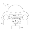
- FIG. 1 is an overall configuration diagram of a non-contact power feeding system 11 according to the first embodiment of the present invention.
- the non-contact power feeding system 11 is a system that performs non-contact power feeding between a power receiving device and a power feeding device in which at least one of them can move.
- the stop station 120 where the moving vehicle 110 stops is a power supply device.
- the moving vehicle 110 is movable with respect to a stop station 120 provided on the road surface 12.
- the moving vehicle 110 is provided with a power receiving coil 111.
- the stopping station 120 is provided with a feeding coil 121.
- the power receiving coil 111 has a facing surface 111 a that can face the power feeding coil 121 on the ground side, and is provided at the bottom of the moving vehicle 110.
- the power receiving coil 111 electromagnetically couples with the power feeding coil 121 to receive AC power in a non-contact manner.
- the non-contact power feeding from the power feeding coil 121 to the power receiving coil 111 is performed based on a magnetic field resonance method. That is, a resonance capacitor (not shown) for constituting a resonance circuit is connected to each of the feeding coil 121 and the receiving coil 111. Further, for example, the capacitance of the resonance capacitor has the same frequency as the resonance frequency of the power supply resonance circuit including the power supply coil 121 and the resonance capacitor and the resonance frequency of the power reception resonance circuit including the power reception coil 111 and the resonance capacitor. It is set to be.
- the moving vehicle 110 is provided with a power receiving circuit 112 and a storage battery 113.
- the power receiving circuit 112 is a power conversion circuit that converts the received power received from the power supply coil 121 into DC power and supplies the DC power to the storage battery 113. That is, the power receiving circuit 112 charges the storage battery 113 by supplying a charging current corresponding to the charging state of the storage battery 113 to the storage battery 113.
- the storage battery 113 is a secondary battery capable of storing sufficient power as a driving power source for the mobile vehicle 110, and is, for example, a lithium ion secondary battery or a nickel hydride secondary battery.
- the power feeding coil 121 has a facing surface 121 a that can face the power receiving coil 111, and is provided on the road surface 12.
- the stop station 120 is provided with a power supply circuit 122 and an external power source 123.
- the power feeding circuit 122 is a power conversion circuit that converts power supplied from the external power source 123 into AC power corresponding to the resonance frequency of magnetic resonance type non-contact power feeding and supplies the AC power to the power feeding coil 121.
- the external power supply 123 is, for example, a commercial power supply, a solar battery, wind power generation, and the like, and supplies the power to the power feeding circuit 122.
- the non-contact power feeding system 11 includes a foreign matter removing device 130 that removes foreign matters placed between the power feeding coil 121 and the power receiving coil 111 during non-contact power feeding.
- the foreign substance exclusion device 130 according to the present embodiment includes a housing 131 that surrounds the power supply coil 121 and a cover 132 that covers the power supply coil 121 by covering the housing 131.
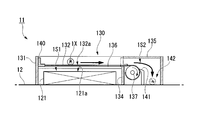
- FIG. 2 is a configuration diagram of the foreign matter exclusion apparatus 130 according to the first embodiment of the present invention.
- reference numeral 1X represents an example of a metallic foreign object.
- the casing 131 has a wall portion 133 that is substantially rectangular in a plan view, and the inside of the wall portion 133 is partitioned into two spaces 1S1 and 1S2 by a partitioning portion 134.
- the space 1S1 is covered with a cover 132, and the space 1S2 is covered with a roof portion 135.
- a feeding coil 121 is accommodated in the space 1S1.
- the casing 131 functions as an electromagnetic shield for EMC (Electro Magnetic Compatibility) countermeasures of the feeding coil 121.
- the casing 131 has a wall 133 standing up from the road surface 12 at a height equal to or higher than the power supply coil 121, and also functions as a physical shield that prevents foreign matter from entering from the side surface to the inside.
- the partition part 134 is lower than the wall part 133, it is formed with the same material as the wall part 133, and does not exert electromagnetic influence on the space 1S2.
- the roof part 135 may also be formed of the same material as the wall part 133.
- the cover 132 has a closed position (shown by a solid line in FIG. 2) that covers the opposing surface 121a of the power supply coil 121, and an open position (shown by a two-dot chain line in FIG. 2) that retreats from the opposing surface 121a of the power supply coil 121. , See FIG. 1).
- a slide guide 136 is provided on the inner side surface of the wall portion 133, and the cover 132 can slide in the horizontal direction along the slide guide 136.
- the cover 132 is formed so as to be wound into a roll by a winder 137 (winding means) provided in the space 1S2.
- the cover 132 of the present embodiment is formed in a sheet shape having a predetermined rigidity, and slides between a closed position and an open position by winding / rewinding of the winder 137. When rewinding, the cover 132 may be pulled by a string (not shown).
- the surface 132a (mounting surface) of the cover 132 may be subjected to surface processing (for example, polytetrafluoroethylene processing) in which foreign matter is difficult to adhere.
- the cover 132 is provided with a hook member 140 (foreign material accompanying means).
- the hook member 140 is integrally attached to the rear end portion of the cover 132 wound up in a roll shape. Both end portions of the hook member 140 are supported by a slide guide 136 and are slidable together with the cover 132 in the horizontal direction.
- the slide guide 136 is provided at substantially the same height as the top of the partition part 134, and the hook member 140 can slide without colliding with the partition part 134.
- the hook member 140 causes the foreign matter placed on the cover 132 to accompany the slide of the cover 132 from the closed position to the open position.
- the hook member 140 protrudes above the surface 132a of the cover 132 on which the foreign matter is placed.
- the hook member 140 of the present embodiment is an L-shaped hook, and an upper end portion of the hook member 140 protrudes upward to a position where it comes into contact with the roof portion 135 and stops.
- the hook member 140 hits the roof portion 135 and stops, thereby functioning as a stopper for winding the cover 132.
- the cover 132 and the hook member 140 are disposed near the power supply coil 121 in a wound state, and thus may be formed of a nonmagnetic and nonconductive material.
- a blade member 141 is provided in the space 1S2.
- the blade member 141 scrapes off foreign matter adhering to the cover 132.
- foreign matters such as empty cans
- foreign materials that have adhesive properties such as gum with silver paper
- the foreign material which does not have adhesiveness may be mounted on the foreign material which has adhesiveness. The blade member 141 physically removes such foreign matter.
- the tip of the blade member 141 is disposed in contact with or close to the surface 132a of the cover 132 wound in a roll shape by the winder 137. As shown in FIG. 2, when the tip of the blade member 141 is brought into contact with the surface 132a of the cover 132, the blade member 141 can be deformed following the cover 132 whose diameter increases according to the number of rotations. You may form from the material which can be elastically deformed.
- the blade member 141 is erected from the road surface 12, and prevents the scraped foreign matter from entering the winder 137.
- a foreign matter collecting unit 142 (foreign matter collecting means) is provided in the space 1S2.
- the foreign matter collection unit 142 has a size that can accommodate foreign matters assumed to be placed on the cover 132.
- the foreign material recovery part 142 of this embodiment is formed by the wall part 133 and the blade member 141, and the upper part is covered with the roof part 135 so that the recovered foreign material is not blown off by wind or the like.
- the roof portion 135 is provided so as to be openable and closable with respect to the wall portion 133 by a hinge mechanism (not shown), and the collected foreign matter can be taken out by opening the roof portion 135.
- the non-contact power feeding system 11 performs non-contact power feeding between the moving vehicle 110 and the stop station 120.
- the magnetic field resonance method is adopted for power transmission between the power feeding coil 121 and the power receiving coil 111. Power feeding by the magnetic field resonance method is resistant to displacement of resonance coils provided in both the moving vehicle 110 and the stop station 120, and can realize high-efficiency and long-distance power transmission.
- the non-contact power feeding system 11 includes a foreign matter removing device 130 that removes foreign matters placed between the power feeding coil 121 and the power receiving coil 111 during non-contact power feeding.
- a foreign object may be placed on the opposing surface 121a of the power supply coil 121.
- the foreign substance exclusion device 130 has a cover 132 that covers the opposing surface 121 a of the power feeding coil 121.
- the cover 132 is located at the closed position on the facing surface 121a of the power feeding coil 121 when non-contact power feeding is not performed, and prevents foreign matter from being directly placed on the facing surface 121a. Intrusion of foreign matter from the side of the power supply coil 121 due to wind or the like is prevented by the casing 131 that also functions as an electromagnetic shield.
- the cover 132 When performing non-contact power feeding, the cover 132 is wound by the winder 137 and slides to an open position where it is retracted from the facing surface 121 a of the power feeding coil 121. At this time, the foreign matter (for example, an empty can) placed on the surface 132a of the cover 132 tends to fall from the rear end portion of the cover 132 without following the slide of the cover 132 due to inertial force.
- the part is provided with a hook member 140.
- the hook member 140 protrudes upward from the surface 132a on which the foreign matter is placed, and the foreign matter can be caused to accompany the slide of the cover 132 by hooking the foreign matter placed on the surface 132a.
- the cover 132 is wound up until the hook member 140 comes into contact with the roof portion 135 and stops, and is retracted from the facing surface 121a of the power feeding coil 121.
- the foreign matter placed on the cover 132 also accompanies the slide of the cover 132 and is removed from the facing surface 121 a of the power feeding coil 121.
- the foreign matter removing device 130 retreats the foreign matter together with the cover 132 from the facing surface 121a without dropping the foreign matter from the cover 132 due to an inclination or the like, so that the power feeding coil 121 and the receiving coil can be used regardless of the nature of the foreign matter.
- the foreign matter can be reliably removed from the space 111, and the uncertainty of foreign matter removal can be eliminated.
- the cover 132 slides in a direction intersecting with the opposing direction of the power feeding coil 121 and the power receiving coil 111, a space in the height direction is not required, and the foreign object exclusion device 130 is disposed between the moving vehicle 110 and the road surface 12. Can fit in a narrow space. Furthermore, in this embodiment, it has the winder 37 which winds up the cover 132 in roll shape. According to this configuration, since the winder 137 winds the cover 132 in a roll shape, it is not necessary to secure a large space at the slide destination of the cover 132 (on the right side in FIG. 2), and the planar area of the foreign matter removing apparatus 130 is eliminated. The space can be saved.
- the foreign matter falls off from the cover 132 wound up in a roll shape and is collected by the foreign matter collecting unit 142. Thereby, even if the cover 132 is rewound, the foreign matter does not return to the facing surface 121a again. Further, in the present embodiment, even if foreign matter adheres to the cover 132, it can be scraped off by the blade member 141, and the foreign matter can be collected in the foreign matter collection unit 142.
- the foreign substance recovery unit 142 is separated from the power supply coil 121 and is not affected by a magnetic field by an electromagnetic shield such as the partition unit 134. Therefore, even if the collected foreign material is a metal, it does not generate heat, and even if it generates heat, the feeding coil 121 is not damaged by heat.
- the non-contact power feeding system 11 that feeds power by causing the power feeding coil 121 and the power receiving coil 111 according to the above-described embodiment to face each other in a non-contact manner, covers the facing surface 121a of the power feeding coil 121, A cover 132 slidable between the open position retracted from the facing surface 121a, and a hook member 140 that causes the foreign matter placed on the cover 132 to accompany the slide of the cover 132 from the closed position to the open position. . Therefore, the non-contact power feeding system 1 can be obtained in which the foreign matter placed on the cover 132 can be reliably removed from between the power feeding coil 121 and the power receiving coil 111.
- FIG. 3 is a configuration diagram of the foreign matter exclusion apparatus 130 according to the second embodiment of the present invention.
- the structure of the cover 132 differs from the said embodiment.
- the cover 132 of the second embodiment includes a closed position (shown by a solid line in FIG. 3) that covers the opposing surface 121a of the power supply coil 121, and an open position (two points in FIG. 3) that retracts from the opposing surface 121a of the power supply coil 121. (Shown by a chain line).
- a slide guide 136 is provided on the inner surface of the wall 133, and the cover 132 is configured to be slidable in the horizontal direction along the slide guide 136.
- the cover 132 is formed so as to be foldable in a bellows shape by a string winder 150 (folding means) provided in the space 1S2.
- the cover 132 of the present embodiment is formed by folding a sheet material having a spring property into a bellows shape, and a guide piece 151 supported by a slide guide 136 is attached to the tip portion.
- a string 152 is connected to the guide piece 51, and when the string winder 150 winds the string 152, the cover 132 slides to the open position, and the cover 132 is moved by the spring restoring force of the cover 132. Slide to the closed position.
- the cover 132 has a mountain portion 153 (foreign material accompanying means) that is partially folded.
- the peak portion 153 is disposed adjacent to the guide piece 151 and is formed to be higher than the other peak portions of the cover 132.
- the peak portion 153 causes the foreign matter placed on the cover 132 to accompany the slide of the cover 132 from the closed position to the open position.
- the mountain portion 153 protrudes upward to a position where it hits the roof portion 135 and stops.
- the peak portion 153 functions as a stopper for folding the cover 132 by stopping against the roof portion 135.
- the opposing surface 121a of the power supply coil 121 is covered with the cover 132, and the foreign matter placed on the cover 132 is caused to accompany the slide of the cover 132 by the mountain portion 153, thereby making contactless power supply. In this case, it can be excluded from the facing surface 121a.
- the foreign matter is retreated together with the cover 132 from the facing surface 121a as in the above-described embodiment, the uncertainty of foreign matter removal can be eliminated.
- the cover 132 by folding the cover 132 in a bellows shape, it is not necessary to secure a large space at the slide destination of the cover 132, and space saving can be achieved. Further, by forming one of the bellows and forming the mountain portion 153, the foreign substance accompanying means can be integrated with the cover 132, and the number of parts can be reduced and the assemblability can be improved. In the second embodiment, when the cover 132 is closed, the foreign matter also returns to the original position. However, if no foreign matter exists between the power feeding coil 121 and the power receiving coil 111 during non-contact power feeding, no problem occurs.
- the hook member 140 and the mountain portion 153 are exemplified as the foreign object accompanying means, but the present invention is not limited to this configuration.
- an attaching means for attaching a foreign substance to the cover 132 may be employed as the foreign substance accompanying means.
- the adhering means may be, for example, an adhesive sheet attached to the surface 132a of the cover 132 shown in FIG. 1, or may be a magnet sheet that is attracted by a magnetic force if the foreign matter is a magnetic substance.
- power is supplied from the stationary station 120 on the ground and power is supplied to the bottom of the moving vehicle 110, but the direction of power supply is not limited.
- power may be supplied from the wall to the side, front, or rear of the moving vehicle 110, or may be supplied from the ceiling to the roof of the moving vehicle 110.
- the present invention is not limited to this configuration.
- the power supply coil 121 may be provided in the moving vehicle 110 provided in the stop station 120. Therefore, the foreign substance exclusion device 130 may be provided in the power receiving coil 111, or may be provided on both sides of the power feeding coil 121 and the power receiving coil 111.
- the present invention can be applied even if at least one of the power receiving device and the power feeding device is a moving vehicle, or a moving body such as a ship, a submarine, or an aircraft.
- the present invention is particularly effective when combined with a magnetic resonance type non-contact power supply that can tolerate a large displacement, but may be combined with other types of non-contact power supply such as an electromagnetic induction type.
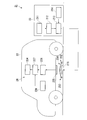
- FIG. 4 is a block diagram showing a main configuration of the non-contact power feeding system 21 according to the present invention.
- Reference numeral 21 in FIG. 4 denotes a non-contact power supply system
- the non-contact power supply system 21 is a system (device) for charging a battery mounted on a vehicle (moving body) such as an electric vehicle or a hybrid vehicle.
- the non-contact power supply system 21 includes a non-contact power supply system 23 installed on the ground and a power receiving device 24 provided on the vehicle 22 (moving body).
- the non-contact power supply system 23 is a third embodiment of the non-contact power supply system according to the present invention.
- the non-contact power supply system 23 is installed on the ground surface, and a vehicle 22 traveling on the ground has a predetermined positional relationship (an electromagnetic coupling circuit described later is formed).
- the electric power (electric power for charging the battery 224) can be transmitted to the power receiving device 24 of the vehicle 22 in a non-contact manner.
- the non-contact power feeding system 23 includes a power source 211, a rectifier circuit 212, a power feeding circuit 213, a power feeding control unit 214, a power feeding coil 215 (power feeding resonator), and the like, and supplies power suitable for non-contact power feeding to the power receiving device 24.
- various types of control necessary for performing non-contact power feeding to the power receiving device 24 are performed.
- the power source 211 is a power source that supplies power necessary to generate power to be transmitted to the vehicle 22, and is a power source that supplies, for example, three-phase AC power having a voltage of 200 [V].
- the power source 211 is not limited to a three-phase AC power source, and may be a power source that supplies single-phase AC power such as a commercial AC power source.
- the rectifier circuit 212 is a circuit that rectifies AC power supplied from the power source 211 and converts it into DC power. Note that a DC power source such as a fuel cell or a solar cell can be used as the power source 211, and in this case, the rectifier circuit 212 can be omitted.
- the power feeding circuit 213 supplies the power supplied from the rectifier circuit 212 to the vehicle 22 in a non-contact manner through an electromagnetic coupling circuit formed by the power feeding coil 215 and the power receiving coil 225 provided in the vehicle 22.
- the power feeding circuit 213 includes a resonance capacitor, and constitutes a power feeding resonance circuit together with the power feeding coil 215. Further, the power feeding circuit 13 converts the DC power from the rectifier circuit 212 into AC power (high frequency power) having a frequency higher than that of the AC power of the power source 211 under the control of the power feeding control unit 214 and converts it into the power feeding coil 215. Output.
- the power feeding control unit 214 controls the power feeding circuit 213 to cause the power feeding circuit 13 to generate power to be supplied to the power receiving device 24.
- the power supply control unit 214 includes a CPU (Central Processing Unit), a memory, and the like, and performs the various controls described above based on a control program prepared in advance.
- CPU Central Processing Unit
- the power supply coil 215 is a coil that supplies the AC power supplied from the power supply circuit 213 to the vehicle 22 in a non-contact manner as described above, and is installed on the ground or embedded to be flush with the ground.
- the power supply coil 215 is formed of, for example, a helical coil having a coil shape dimension defined in advance, and its upper surface side is covered with a cover 230. Details of the cover 230 will be described later.
- the feeding coil 215 may be provided integrally with a container formed of a nonmagnetic material such as plastic.
- the power supply coil 215 supplies power to the power receiving device 24 in a non-contact manner by generating a magnetic field corresponding to the AC power (high frequency power) supplied from the power supply circuit 213.
- the feeding coil 215 may be formed of a so-called solenoid type coil in which the winding axis direction is in the horizontal direction.
- the vehicle 22 is a car that is driven by a driver and travels on a road.
- the vehicle 22 is an electric car or a hybrid car that includes a travel motor as a power generation source, and includes a power receiving device 24 as shown in FIG.
- the vehicle 22 includes components necessary for traveling, such as an engine, a traveling motor, an operation handle, and a brake.
- the power receiving device 24 includes a power receiving coil 225, a power receiving circuit 226, a charging circuit 227, a battery 224, and a power receiving control unit 228.
- the power receiving coil 225 is formed of a helical coil having substantially the same coil diameter as that of the power feeding coil 215 described above. Note that the power receiving coil 225 may be provided integrally with a container formed of a nonmagnetic material such as plastic. Such a power receiving coil 225 is provided on the bottom of the vehicle 22 in such a posture that the coil axis is in the vertical direction (vertical direction) so as to be able to face the power feeding coil 215.
- Both ends of the power receiving coil 225 are connected to the input terminal of the power receiving circuit 226, and an electromotive force is generated when the magnetic field of the power feeding coil 215 acts, and the generated electromotive force is output to the power receiving circuit 226.
- the power receiving coil 225 may be formed of a so-called solenoid type in which the winding axis direction is in the horizontal direction.
- the power receiving circuit 226 receives power (AC power) supplied in a contactless manner through an electromagnetic coupling circuit formed by the power feeding coil 215 and the power receiving coil 225, and converts the received power into DC power for charging. Output to the circuit 227.
- the power reception circuit 226 includes a resonance capacitor, and constitutes a power reception resonance circuit together with the power reception coil 225. Note that the capacitance of the resonance capacitor of the power reception circuit 226 is set so that the resonance frequency of the power reception resonance circuit is the same as the resonance frequency of the power supply resonance circuit described above.
- the charging circuit 227 has an input terminal connected to the output terminal of the power receiving circuit 226 and an output terminal connected to the input terminal of the battery 224, and charges the battery 224 with electric power (DC power) from the power receiving circuit 226.
- the battery 224 is a rechargeable battery (for example, a secondary battery such as a lithium ion battery or a nickel metal hydride battery) mounted on the vehicle 22 and supplies power to a travel motor (not shown).
- the power reception control unit 228 includes a CPU, a memory, and the like, and controls the charging circuit 227 based on a power reception control program prepared in advance.
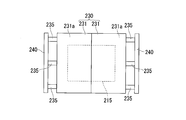
- the cover 230 that covers the upper surface side of the power feeding coil 215 described above is formed by a pair of resin cover members 231 and 231 as shown in FIGS. 5A and 5B, and these cover members 231. 231 is connected to the vibrating portion 232.
- the cover member 231 is formed by a cover body 231a having a rectangular shape in plan view as shown in FIG. 5B and a side plate portion 231b descending from the side edge of the cover body 231a as shown in FIG. 5A.
- cover members 231 and 231 are formed in a side-view mountain shape so that the side in contact with each other is higher and the opposite side is lower. That is, the upper surface of the cover 230 is high at the central portion, and is an inclined surface that gradually descends toward the outside.
- the inclination angle of the cover member 231 is not particularly limited. As will be described later, the foreign material 250 placed on the upper surface is easily guided to the outside (lower side) by the vibration of the cover member 231 and falls from the cover member 231.
- the angle to be. Specifically, the angle is about 10 to 40 degrees.
- the vibration part 232 includes a vibration part coil 233 that generates electric power by receiving a magnetic field generated by the power supply coil 215, and a vibrator 235 that is connected to the vibration part coil 233 via the wiring 234 and connected to the cover member 231.
- the vibration part coil 233 is disposed between the power supply coil 215 and the cover member 231, and is therefore disposed in a space between the power supply coil 215 and the power reception coil 225 between the ground surface and the vehicle 22.
- the vibrating portion coil 233 is a helical coil in which a conducting wire such as a round wire or a flat wire is wound spirally in the same plane. And this vibrating part coil 233 is in a state where its winding surface (surface orthogonal to the coil axis) is closer to orthogonal to the magnetic flux 2A generated when non-contact power supply is performed from the power supply coil 215 to the power reception coil 225.
- a conducting wire such as a round wire or a flat wire is wound spirally in the same plane.
- this vibrating part coil 233 is in a state where its winding surface (surface orthogonal to the coil axis) is closer to orthogonal to the magnetic flux 2A generated when non-contact power supply is performed from the power supply coil 215 to the power reception coil 225.
- the vibration unit coil 233 may be disposed so as to be partially removed from the space between the power feeding coil 215 and the power receiving coil 225.
- the vibration unit coil 233 may be disposed so as to be partially removed from the space between the power feeding coil 215 and the power receiving coil 225.
- the vibrating portion coil 233 provided on the one cover member 231 side and the vibrating portion coil 233 provided on the other cover member 231 side have respective winding directions of the conducting wires. It is reversed. That is, for example, the vibrating portion coil 233 on one cover member 231 side is formed in a left-handed manner, and the vibrating portion coil 233 on the other cover member 231 side is formed in a right-handed manner.
- the vibrator 235 is formed by a conductive polymer actuator 236 that vibrates due to the electric power generated by the vibration part coil 233.
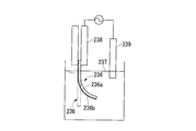
- the conductive polymer actuator 236 is formed by an element that bends and stretches. As shown in FIG. 6, for example, a polypyrrole (PPy) 236a formed into a strip (elongate rectangular plate) and a polypyrrole 236a are formed. It is formed by Kapton tape 236b stuck on one surface.
- the conductive polymer actuator 236 having such a configuration includes a working electrode 238 connected to the polypyrrole 236a in a state immersed in the solution 237 and a counter electrode 239 immersed in the solution 237 as shown in FIG.
- a voltage is applied between them, ions in the solution 237 enter and exit only from the surface on the polypyrrole 236a side, and the volume expands and contracts relative to the Kapton tape 236b side, so that the element bends and stretches.
- a solution obtained by dissolving sodium p-toluenesulfonate (p-TSNa) in deionized water is used as the solution 237.
- the vibrator 235 is formed by stacking a pair of conductive polymer actuators 236 and 236 in a state where they are in contact with each other with the Kapton tape 236b side inside. Further, as shown in FIG. 5A, the vibrator 235 has one end held by the support plate 240 standing on the ground, and the other end face is in contact with the outer surface of the side plate portion 231 b outside the cover member 231. Connected to this. Note that three vibrators 235 are connected to the cover member 231 as shown in FIG. 5B, for example. However, the number of vibrators 235 connected to the cover member 231 is arbitrarily set according to the size of the cover member 231 and the ability of the vibrator 235.
- a coil spring may be interposed between the support plate 240 and the cover member 231 in order to stably hold the cover member 231.
- the cover member 231 may be supported by a support member (not shown) different from the support plate 240.
- a working electrode (not shown) is provided on the support plate 240 side of the vibrator 235, and a wiring 234 connected to one end of the vibrating portion coil 233 is connected to the working electrode.
- a solution storage cylinder (not shown) is externally inserted in the middle part of the vibrator 235, and the middle part of the vibrator 235 is slidably held with respect to the solution storage cylinder. The distal end portion of the vibrator 235 is pulled out from the solution storage cylinder and is in contact with the outer surface of the side plate portion 231b outside the cover member 231 as described above.
- the solution container is filled with a solution (not shown) in a liquid-tight manner, and a counter electrode (not shown) is disposed in the solution.
- a wiring 234 connected to the other end of the vibration part coil 233 is connected to the counter electrode.
- the vibrator 235 is formed by a pair of conductive polymer actuators 236, but the working electrode (not shown) of the vibrator 235 is a polypyrrole 236a in each of the pair of conductive polymer actuators 236. Functions as a working electrode.
- the counter electrode arranged in the solution storage cylinder is also a common electrode for the pair of conductive polymer actuators 236.
- the vibrator 235 is displaced in the length direction as the entire volume expands and contracts as ions in the solution 237 enter and exit from both sides of the polypyrrole 236a. That is, it expands and contracts in the length direction.
- the vibration unit 232 generates power by the magnetic field formed by the vibration coil 233 by the power supply coil 215, and this power is supplied to the vibrator 235 via the wiring 234.
- the cover member 231 is vibrated by expanding and contracting in the vertical direction. That is, the vibrator 235 receives the magnetic field (magnetic flux 2A) corresponding to the AC power (high-frequency power) generated from the power supply coil 215, thereby supplying high-frequency AC power to the vibrator 235.
- the volume expansion and contraction are repeated at high speed, and the length in the length direction is displaced at high speed.
- one end of the vibrator 235 is held and fixed by the support plate 240, and the end face of the other end is in contact with the outer surface of the side plate portion 231b outside the cover member 231, and therefore the vibrator 35 is attached to the other end.
- the cover member 231 is vibrated in small increments by expanding and contracting.
- Such vibration of the cover member 231 by the vibration part 232 is similarly performed by both the pair of cover members 231 and 231.
- the winding direction of the conducting wire is reversed between the vibrating portion coil 233 connected to one cover member 31 side and the vibrating portion coil 233 connected to the other cover member 231 side. Yes. Therefore, the phase of the AC power (AC voltage) generated by the vibrating coil 233 is reversed between the vibrator 235 provided on one cover member 231 and the vibrator 235 provided on the other cover member 231.
- the vibrator 235 on one side is extended, the vibrator 235 on the other side is shortened. Conversely, when the vibrator 235 on one side is shortened, the vibrator 235 on the other side is extended.
- the pair of cover members 231 and 231 are both displaced in the same direction. That is, when one cover member 231 is displaced in the right direction in FIG. 5A, the other cover member 231 is also displaced in the right direction in the drawing, and when one cover member 231 is displaced in the left direction in the drawing, the other cover member 231 is displaced. Is also displaced leftward on the page. Therefore, since the pair of cover members 231 and 231 are integrally displaced, the cover 230 vibrates smoothly, and the foreign material 250 placed thereon can be easily dropped from the cover 230.
- the cover 230 including the pair of cover members 231 and 231 is provided so as to cover the power feeding coil 215, and the cover members 231 and 231 are generated by the power feeding coil 215.
- a vibrating part 232 that vibrates by the magnetic flux 2A and vibrates the cover 230 is connected. Since the cover 230 is vibrated using the magnetic flux generated in the power supply coil 215, a dedicated power source is not required. Therefore, the arrangement of the dedicated power source complicates the device, or the dedicated power source can be used. Costs can be prevented from increasing.
- the foreign material 250 placed on the cover 230 and thus placed on the power supply coil 215 via the cover 230 is inclined by the vibration of the vibrator 235 of the vibration unit 232 having a relatively simple configuration. It can be reliably removed from the cover 230 by moving it outward in the lower direction and dropping it from the cover member 231. Therefore, it is possible to prevent the transmission (power transmission) efficiency of the feeding coil 215 from being reduced by the foreign object 250 with a relatively simple configuration without using another dedicated power source.
- cover members 231 and 231 constituting the cover 230 are inclined surfaces whose upper surfaces descend as the outer surface goes outward, the foreign material 250 is moved downwardly in the inclination direction of the cover member 231 by the vibration of the vibration part 232.
- the cover member 231 can be easily moved and dropped.
- a pair of conductive polymer actuators 236 and 236 are used as the vibrator 235 of the vibration unit 232. Since the conductive polymer actuators 236 and 236 are driven at a low voltage, the vibrator 235 is easily driven by the electric power obtained by the vibrating coil 233 to vibrate the cover members 231 and 231. Furthermore, since the conductive polymer actuator 236 is much lighter than a motor or the like, it can be easily attached to the cover member 231 (cover 230).
- FIG. 7 is a side view of an essential part of a fourth embodiment of the non-contact power feeding system of the present invention. 7 is different from the non-contact power supply system 23 of the third embodiment shown in FIGS. 4 and 5A in the way of attaching the vibrator 235 to the cover members 231 and 231 (cover 230). .
- a vibrator 235 comprising a pair of conductive polymer actuators 236 and 236 is held by a support plate 240 with one end standing on the ground, and the end face of the other end is
- the cover member 231 is in contact with and connected to the bottom surface of the cover main body 231a. Therefore, in this embodiment, the vibration part coil 233 receives the magnetic field (magnetic flux 2A) corresponding to the alternating current power (high frequency power) generated from the power supply coil 215, thereby supplying high frequency alternating current power to the vibrator 235, thereby vibrating.
- the child 235 vibrates the cover main body 231a in the vertical direction.
- the foreign material 250 placed on the cover 230 is moved downwardly in the inclination direction of the cover member 231 by the vibration of the vibrator 235 of the vibration unit 232 having a relatively simple configuration. It can be reliably removed from the cover 230 by being moved outward and falling from the cover member 231. Therefore, it is possible to prevent the transmission (power transmission) efficiency of the feeding coil 215 from being reduced by the foreign object 250 with a relatively simple configuration without using another dedicated power source.
- FIG. 8 is a side view of an essential part of a fifth embodiment of the non-contact power feeding system of the present invention.
- the non-contact power feeding system shown in FIG. 8 is different from the non-contact power feeding system according to the fourth embodiment shown in FIG. 7 in the configuration of the vibration part connected to the cover members 231 and 231 (cover 230). That is, in the present embodiment, a vibrator 242 made of a magnetostrictive material is used for the vibrating portion 241.
- the magnetostrictive material ferromagnetic materials such as cobalt and nickel, and alloys thereof are used. Such a magnetostrictive material expands and contracts due to a dimensional change when a magnetic field is applied. Therefore, using such a magnetostrictive material, the vibrator 242 is formed so that the length direction is expanded and contracted by a magnetic field. Then, like the vibrator 235 of the fourth embodiment, one end of the vibrator 242 is held by the support plate 240 standing on the ground, and the other end face is on the bottom surface of the cover body 231a of the cover member 231. It arrange
- the vibrator 242 directly expands and contracts due to the magnetic field (magnetic flux 2A) from the power supply coil 215, so that it is not necessary to use the vibration part coil 233 used in the previous embodiment. That is, the vibrator 242 expands and contracts by receiving a magnetic field (magnetic flux 2A) corresponding to AC power (high frequency power) generated from the power supply coil 215, and thereby the vibrator 242 vibrates the cover body 231a in the vertical direction.
- the foreign object 250 placed on the cover 230 is placed outside the cover member 231 in the inclination direction by the vibration of the vibrator 242 of the vibration unit 241 having a simple configuration. It can be reliably removed from the cover 230 by being moved in the direction and dropping from the cover member 231. Therefore, it is possible to prevent the transmission (power transmission) efficiency of the feeding coil 215 from being reduced by the foreign object 250 with a simple configuration without using another dedicated power source. Further, since the vibrator 242 made of a magnetostrictive material is used for the vibration part 241, it is not necessary to use the vibration part coil 233, and therefore the structure of the vibration part 241 can be simplified.
- FIG. 9 is a side view of an essential part of a modification of the non-contact power feeding system of the present invention.
- the non-contact power feeding system shown in FIG. 9 has a configuration in which the cover 230 (cover members 231 and 231) also serves as a vibration part, unlike the previous embodiment. That is, the cover 230 (cover members 231 and 231) is formed of the above-described magnetostrictive material, and therefore the cover 230 itself is received by receiving a magnetic field (magnetic flux 2A) corresponding to the AC power (high-frequency power) generated from the feeding coil 215. Expands and contracts, for example, vibrates in the vertical direction.
- a magnetic field magnetic flux 2A
- AC power high-frequency power
- the cover 230 (cover members 231 and 231) is formed of a metal that is a magnetostrictive material and also a conductive material, an eddy current is generated in the cover 230 by receiving a magnetic field (magnetic flux 2A). . Therefore, a slit for blocking the eddy current is provided in the cover 30 so that the cover does not generate heat due to the eddy current.
- the cover members 231 and 231 are supported by a support member (not shown) in a state of covering the power supply coil 215 above.
- the foreign object 250 placed on the cover 230 is moved outward by the cover 230 serving as a vibrating portion having a simple configuration to the lower side in the inclination direction of the cover member 231. Then, it can be reliably removed from the cover 230 by dropping from the cover member 231. Therefore, it is possible to prevent the transmission (power transmission) efficiency of the feeding coil 215 from being reduced by the foreign object 250 with a simple configuration without using another dedicated power source.
- the cover 230 is formed by a pair of cover members 231 and 231 and these cover members 231 and 231 are arranged in a mountain shape.
- the cover member 231 is formed in a triangular shape in plan view, and these covers
- the cover 230 may be formed in a pyramid shape by combining three or more members 231.
- the upper surface of the cover 230 is an inclined surface.
- the upper surface of the cover 230 may be a horizontal surface instead of the inclined surface. Also in that case, when the cover is vibrated by the vibration part, the foreign matter on the cover easily falls from the cover and is removed.
- the non-contact electric power feeding system which can remove
- Non-contact power feeding system 111 225 Power receiving coil 121, 215 Power feeding coil 121a Opposing surface 130 Foreign matter removing device 132, 230 Cover 132a Surface (mounting surface) 137 Winding machine (winding means) 140 Hook member (accompanying foreign matter) 141 Blade member 142 Foreign matter collecting part (foreign matter collecting means) 150 String winder (folding means) 153 Yamabe (accompaniment with foreign objects) 1X, 250 Foreign object 22 Vehicle (moving body) 231 Cover members 232, 241 Vibrating portion 233 Vibrating portion coil 234 Wiring 235, 242 Vibrator 236 Conductive polymer actuator 2A ... Magnetic flux
Landscapes
- Engineering & Computer Science (AREA)
- Power Engineering (AREA)
- Computer Networks & Wireless Communication (AREA)
- Transportation (AREA)
- Mechanical Engineering (AREA)
- Charge And Discharge Circuits For Batteries Or The Like (AREA)
- Electric Propulsion And Braking For Vehicles (AREA)
- Current-Collector Devices For Electrically Propelled Vehicles (AREA)
Abstract
給電コイル(121)と受電コイル(111)とを非接触で対向させて給電を行う非接触給電システム(11)であって、非接触給電システム(11)は、給電コイル(121)の対向面(121a)上を覆う閉塞位置と、対向面(121a)上から退避する開放位置と、の間でスライド可能なカバー(132)と、カバー(132)に載った異物を、カバー(132)の閉塞位置から開放位置へのスライドに同行させるフック部材(140)と、を有する。
Description
本発明は、非接触給電システムに関する。
本願は、2013年11月18日に日本国に出願された特願2013-237918号と、2014年1月14日に日本国に出願された特願2014-004642号と、に基づき優先権を主張し、その内容をここに援用する。
本願は、2013年11月18日に日本国に出願された特願2013-237918号と、2014年1月14日に日本国に出願された特願2014-004642号と、に基づき優先権を主張し、その内容をここに援用する。
近年、給電コイルと受電コイルとを非接触で対向させて給電を行う非接触給電システムが注目されている。つまり、近年、給電側のコイル(給電コイル)を地上に設置、あるいは地面に面一になるように埋設し、受電側のコイル(受電コイル)を備えた電気自動車を給電コイル上に停車させ、給電コイルから受電コイルに対して非接触で電力を供給する、非接触給電システムが知られている。
非接触給電システムは、磁界共鳴方式や電磁誘導方式を採用しており、電気自動車等の移動車両の給電に応用が期待されている。しかしながら、この非接触給電システムは、給電コイルと受電コイルとの間に異物が存在すると給電効率が落ち、また、その異物が空き缶等の金属であると磁界の影響を受けて発熱してしまう可能性がある。
即ち、給電コイルと自動車(車両)の受電コイルとの間に金属等の導電体や磁性体からなる異物が入り込むと、この異物に渦電流が生じ、ジュール発熱によって異物の温度が上昇する。すると、この異物の温度上昇に伴われて給電コイルも温度上昇する。また、異物によって給電コイルが作る磁界が弱められるため、その伝送(送電)効率が少なからず低下してしまう。
非接触給電システムは、磁界共鳴方式や電磁誘導方式を採用しており、電気自動車等の移動車両の給電に応用が期待されている。しかしながら、この非接触給電システムは、給電コイルと受電コイルとの間に異物が存在すると給電効率が落ち、また、その異物が空き缶等の金属であると磁界の影響を受けて発熱してしまう可能性がある。
即ち、給電コイルと自動車(車両)の受電コイルとの間に金属等の導電体や磁性体からなる異物が入り込むと、この異物に渦電流が生じ、ジュール発熱によって異物の温度が上昇する。すると、この異物の温度上昇に伴われて給電コイルも温度上昇する。また、異物によって給電コイルが作る磁界が弱められるため、その伝送(送電)効率が少なからず低下してしまう。
特許文献1には、磁界を用いて電力伝送を行う送電部と、電力伝送の際の送電経路付近における異物を排除する異物排除動作部と、を備えた給電装置が開示されている。この異物排除動作部は、送電部を収容する収容部を傾斜、回転及び振動のうち少なくとも1つの動作により異物を排除する。
特許文献2には、充電開始前からすでに給電コイル上に存在している異物を掃き出す掃出部を備えた電気自動車が開示されている。この掃出部は、電気自動車の底面に配置されると共に、収納状態と掃出可能状態との間を可動とされ、電気自動車が給電部に近づいたときに掃出可能状態に移動する。
特許文献3には、動物や異物が地上設備トランスジューサに載らないようにするドーム状のハウジングを備えた電機システムが開示されている。このドーム状のハウジングは、複数の高さに配置された複数の点を持つ外面を含み、その複数の点のうち少なくとも一つが第1高さを有し、その複数の点の他の点が第1高さよりも低い夫々の高さを有する。
また、例えば特許文献4に、充電面を水平面に対して角度を持った傾斜面又は鉛直面にした、異物による発熱を防止する充電装置が知られている。
特許文献5には、給電コイルと受電コイルのうちの少なくとも一方が開閉可能な巻取式のロールスクリーンに覆われており、給電コイルと受電コイルの表面(動作面)が汚れることを防止する非接触給電システムが開示されている。
特許文献6には、非接触給電する際に、上方に移動して受電コイルを覆う部材と密着するように形成された、給電コイルを覆う上に凸の円錐形状の部材に載った異物が、給電コイルの移動に伴って円錐形状の斜面に沿って落下する非接触給電システムが開示されている。
特許文献7には、非接触給電中に給電面上の異物の存在を感知すると、2つの給電コイルのうちの一方に特有の周波数の電流を供給し、上記2つの給電コイルから2つの異なる周波数の電流による2つの異なる変動磁界が生じ、その結果、給電面が第3の周波数で振動する非接触給電システムが開示されている。
特許文献8には、高分子アクチュエータを左右交互に屈曲することによりブラシを駆動し、レンズやCCDをクリーニングする装置が開示されている。
特許文献9には、超磁歪素子により搬送ローラを振動させる異物付着防止機能付き用紙搬送装置とそれを備えた画像形成装置が開示されている。
また、例えば特許文献4に、充電面を水平面に対して角度を持った傾斜面又は鉛直面にした、異物による発熱を防止する充電装置が知られている。
特許文献5には、給電コイルと受電コイルのうちの少なくとも一方が開閉可能な巻取式のロールスクリーンに覆われており、給電コイルと受電コイルの表面(動作面)が汚れることを防止する非接触給電システムが開示されている。
特許文献6には、非接触給電する際に、上方に移動して受電コイルを覆う部材と密着するように形成された、給電コイルを覆う上に凸の円錐形状の部材に載った異物が、給電コイルの移動に伴って円錐形状の斜面に沿って落下する非接触給電システムが開示されている。
特許文献7には、非接触給電中に給電面上の異物の存在を感知すると、2つの給電コイルのうちの一方に特有の周波数の電流を供給し、上記2つの給電コイルから2つの異なる周波数の電流による2つの異なる変動磁界が生じ、その結果、給電面が第3の周波数で振動する非接触給電システムが開示されている。
特許文献8には、高分子アクチュエータを左右交互に屈曲することによりブラシを駆動し、レンズやCCDをクリーニングする装置が開示されている。
特許文献9には、超磁歪素子により搬送ローラを振動させる異物付着防止機能付き用紙搬送装置とそれを備えた画像形成装置が開示されている。
特許文献1及び3の技術は、送電部を収容する収容部を傾斜等させるものであるため、電気自動車と地面との間の狭いスペースでは傾斜を大きくとることができず、異物によっては排除が不十分になる可能性がある。また、例えば、異物が銀紙付きガム等であって付着性を有する場合には、傾斜、回転及び振動のいずれであっても異物を排除できない。
特許文献2の技術は、電気自動車に掃出部を搭載しなければならず、電気自動車自体に装置の追加が必要となる。
特許文献2の技術は、電気自動車に掃出部を搭載しなければならず、電気自動車自体に装置の追加が必要となる。
また、例えば車両に対する非接触給電システムにあっては、給電面を単に傾斜させるだけでは異物を確実に落とすことが難しかった。
本発明は、上記事情に鑑み、載置された異物を給電コイルと受電コイルとの間から確実に排除することができる非接触給電システムの提供を目的とする。
本発明の第1の態様は、給電コイルと受電コイルとを非接触で対向させて給電を行う非接触給電システムであって、前記給電コイル及び前記受電コイルの少なくともいずれか一方の対向面上を覆う閉塞位置と、上記対向面上から退避する開放位置と、の間でスライド可能なカバーと、前記カバーに載った異物を、前記カバーの前記閉塞位置から前記開放位置へのスライドに同行させる異物同行手段と、を有する。
本発明の第1の態様では、給電コイル若しくは受電コイルの対向面上をカバーで覆い、そのカバーに載った異物を、異物同行手段によってカバーのスライドに同行させて、非接触給電の際には対向面上から排除する。本発明の第1の態様では、傾斜等により異物をカバーから脱落させず、異物をカバーごと対向面上から退避させるため、異物排除の不確実性を解消することができる。
本発明の第1の態様では、給電コイル若しくは受電コイルの対向面上をカバーで覆い、そのカバーに載った異物を、異物同行手段によってカバーのスライドに同行させて、非接触給電の際には対向面上から排除する。本発明の第1の態様では、傾斜等により異物をカバーから脱落させず、異物をカバーごと対向面上から退避させるため、異物排除の不確実性を解消することができる。
本発明の第2の態様は、上記第1の態様において、上記異物同行手段は、上記カバーに設けられ、上記異物が載る載置面よりも上方に突出するフック部材を有する。
本発明の第2の態様では、上記カバーにフック部材を設け、このフック部材にカバーの載置面上に載った異物を引っ掛けることで、異物をカバーのスライドに同行させることができる。
本発明の第2の態様では、上記カバーにフック部材を設け、このフック部材にカバーの載置面上に載った異物を引っ掛けることで、異物をカバーのスライドに同行させることができる。
本発明の第3の態様は、上記第1または第2の態様において、上記カバーをロール状に巻き取る巻き取り手段を有する。
本発明の第3の態様では、カバーをロール状に巻き取ることによって、カバーのスライド先に大きなスペースを確保する必要がなくなり、省スペース化を図ることができる。
本発明の第3の態様では、カバーをロール状に巻き取ることによって、カバーのスライド先に大きなスペースを確保する必要がなくなり、省スペース化を図ることができる。
本発明の第4の態様は、上記第1または第2の態様において、上記カバーを蛇腹状に折り畳む折り畳み手段を有する。
本発明の第4の態様では、カバーを蛇腹状に折り畳むことによって、カバーのスライド先に大きなスペースを確保する必要がなくなり、省スペース化を図ることができる。
本発明の第4の態様では、カバーを蛇腹状に折り畳むことによって、カバーのスライド先に大きなスペースを確保する必要がなくなり、省スペース化を図ることができる。
本発明の第5の態様は、上記第1から第4のいずれか一つの態様において、上記異物同行手段は、上記カバーに上記異物を付着させる付着手段を有する。
本発明の第5の態様では、カバーに付着手段を設け、この付着手段によってカバーに異物を付着させることで、異物をカバーのスライドに同行させることができる。
本発明の第5の態様では、カバーに付着手段を設け、この付着手段によってカバーに異物を付着させることで、異物をカバーのスライドに同行させることができる。
本発明の第6の態様は、上記第1から第5のいずれか一つの態様において、上記異物の同行先で、上記カバーに付着している上記異物をそぎ落とすブレード部材を有する。
本発明の第6の態様では、ブレード部材によってカバーに付着した異物をそぎ落とすことで、異物が再び対向面上に戻らないようにすることができる。
本発明の第6の態様では、ブレード部材によってカバーに付着した異物をそぎ落とすことで、異物が再び対向面上に戻らないようにすることができる。
本発明の第7の態様は、上記第1から第6のいずれか一つの態様において、上記異物の同行先で、上記異物を回収する異物回収手段を有する。
本発明の第7の態様では、異物回収手段によってカバーに載った異物を回収することで、異物が再び対向面上に戻らないようにすることができる。
本発明の第7の態様では、異物回収手段によってカバーに載った異物を回収することで、異物が再び対向面上に戻らないようにすることができる。
本発明の第8の態様は、移動体に対して非接触で送電を行う給電コイルと、上記給電コイルを覆うカバーと、前記給電コイルで発生した磁束によって振動し、上記カバーを振動させる、上記カバーに接続されている振動部と、を備える非接触給電システムである。
本発明の第9の態様は、上記第8の態様において、上記カバーは、その上面が外側に行くに連れて下降する傾斜面となっている。
本発明の第10の態様は、上記第8または第9の態様において、上記振動部は、上記給電コイルで発生した磁束を受けて電力を生成する振動部コイルと、上記振動部コイルに接続するとともに上記カバーに接続し、上記振動部コイルで生成した電力によって振動する導電性高分子アクチュエータからなる振動子と、を備える。
本発明の第11の態様は、上記第8または第9の態様において、上記振動部は、磁歪材料からなる振動子によって形成されている。
本発明によれば、載置された異物を給電コイルと受電コイルとの間から確実に排除することができる非接触給電システムが得られる。
以下、本発明の実施形態について図面を参照して説明する。
(第1実施形態)
図1は、本発明の第1実施形態における非接触給電システム11の全体構成図である。
非接触給電システム11は、少なくともいずれか一方が移動可能な受電装置と給電装置との間で非接触給電を行うシステムであり、本実施形態では、図1に示すように、移動車両110が受電装置であり、移動車両110が停車する停車ステーション120が給電装置である。移動車両110は、路面12に設けられた停車ステーション120に対して移動可能である。
図1は、本発明の第1実施形態における非接触給電システム11の全体構成図である。
非接触給電システム11は、少なくともいずれか一方が移動可能な受電装置と給電装置との間で非接触給電を行うシステムであり、本実施形態では、図1に示すように、移動車両110が受電装置であり、移動車両110が停車する停車ステーション120が給電装置である。移動車両110は、路面12に設けられた停車ステーション120に対して移動可能である。
移動車両110には、受電コイル111が設けられている。一方で、停車ステーション120には、給電コイル121が設けられている。受電コイル111は、地上側の給電コイル121と対向可能な対向面111aを有し、移動車両110の底部に設けられている。この受電コイル111は、給電コイル121と電磁的に結合することによって交流電力を非接触で受電する。
本実施形態の非接触給電システム11における給電コイル121から受電コイル111への非接触給電は、磁界共鳴方式に基づいて行われる。すなわち、給電コイル121と受電コイル111とには各々に共振回路を構成するための共振用コンデンサ(不図示)が接続されている。また、例えば共振用コンデンサの静電容量は、給電コイル121と共振用コンデンサとからなる給電共振回路の共振周波数と受電コイル111と共振用コンデンサとからなる受電共振回路の共振周波数とは同一周波数となるように設定されている。
移動車両110には、受電コイル111の他に、受電回路112と、蓄電池113とが設けられている。
受電回路112は、給電コイル121から受電した受電電力を直流電力に変換して蓄電池113に供給する電力変換回路である。すなわち、この受電回路112は、蓄電池113の充電状態に応じた充電電流を蓄電池113に供給することにより蓄電池113を充電する。
蓄電池113は、移動車両110の駆動動力源として十分な電力を蓄えることが可能な二次電池であり、例えばリチウムイオン二次電池やニッケル水素二次電池等である。
受電回路112は、給電コイル121から受電した受電電力を直流電力に変換して蓄電池113に供給する電力変換回路である。すなわち、この受電回路112は、蓄電池113の充電状態に応じた充電電流を蓄電池113に供給することにより蓄電池113を充電する。
蓄電池113は、移動車両110の駆動動力源として十分な電力を蓄えることが可能な二次電池であり、例えばリチウムイオン二次電池やニッケル水素二次電池等である。
一方で、給電コイル121は、受電コイル111と対向可能な対向面121aを有し、路面12上に設けられている。停車ステーション120には、給電コイル121の他に、給電回路122と、外部電源123とが設けられている。
給電回路122は、外部電源123から供給される電力を磁界共鳴方式の非接触給電の共振周波数に応じた交流電力に変換して給電コイル121に供給する電力変換回路である。
外部電源123は、例えば商用電源、太陽電池、風力発電等であって、その電力を給電回路122に供給する。
給電回路122は、外部電源123から供給される電力を磁界共鳴方式の非接触給電の共振周波数に応じた交流電力に変換して給電コイル121に供給する電力変換回路である。
外部電源123は、例えば商用電源、太陽電池、風力発電等であって、その電力を給電回路122に供給する。
非接触給電システム11は、非接触給電の際に、給電コイル121及び受電コイル111の間に載置された異物を排除する異物排除装置130を有する。
本実施形態の異物排除装置130は、給電コイル121の周囲を囲う筐体131と、筐体131に蓋をして給電コイル121を覆うカバー132と、を有する。
本実施形態の異物排除装置130は、給電コイル121の周囲を囲う筐体131と、筐体131に蓋をして給電コイル121を覆うカバー132と、を有する。
図2は、本発明の第1実施形態における異物排除装置130の構成図である。なお、符号1Xは、金属製の異物の一例を示している。
筐体131は、平面視略矩形状の壁部133を有し、壁部133内が仕切り部134によって二つの空間1S1,1S2に仕切られている。空間1S1は、カバー132によって蓋をされ、空間1S2は、屋根部135によって蓋をされている。
筐体131は、平面視略矩形状の壁部133を有し、壁部133内が仕切り部134によって二つの空間1S1,1S2に仕切られている。空間1S1は、カバー132によって蓋をされ、空間1S2は、屋根部135によって蓋をされている。
空間1S1には、給電コイル121が収容されている。筐体131は、給電コイル121のEMC(Electro Magnetic Compatibility)対策の電磁的シールドとして機能する。また、筐体131は、壁部133が路面12から給電コイル121の高さ以上に立設しており、側面から内部への異物の侵入を阻止する物理的シールドとしても機能する。なお、仕切り部134は、壁部133よりも低いが、壁部133と同じ材料によって形成されており、空間1S2に電磁的な影響を与えない。また、屋根部135も壁部133と同じ材料によって形成しても良い。
カバー132は、給電コイル121の対向面121a上を覆う閉塞位置(図2において実線で示す)と、給電コイル121の対向面121a上から退避する開放位置(図2において二点鎖線で示す、また、図1参照)と、の間でスライド可能に構成されている。本実施形態では、壁部133の内側面にスライドガイド136が設けられており、カバー132は、スライドガイド136に沿って水平方向にスライド可能である。
カバー132は、空間1S2に設けられた巻取機137(巻き取り手段)によってロール状に巻き取り可能に形成されている。本実施形態のカバー132は、所定の剛性を有するシート状に形成されており、巻取機137の巻き取り/巻き戻しによって閉塞位置と開放位置との間をスライドする。なお、巻き戻しの際には、不図示の紐によって、カバー132を牽引してもよい。このカバー132の表面132a(載置面)は、異物が付着し難い表面加工(例えばポリテトラフルオロエチレン加工)をしても良い。
カバー132には、フック部材140(異物同行手段)が設けられている。フック部材140は、ロール状に巻き取られるカバー132の後端部に一体的に取り付けられている。フック部材140の両端部は、スライドガイド136に支持されており、カバー132と共に、水平方向にスライド可能である。なお、スライドガイド136は、仕切り部134の頂部と略同じ高さに設けられており、フック部材140は、仕切り部134と衝突しないでスライド可能である。
このフック部材140は、カバー132に載った異物を、カバー132の閉塞位置から開放位置へのスライドに同行させる。フック部材140は、異物が載るカバー132の表面132aよりも上方に突出している。本実施形態のフック部材140は、L字フックであり、その上端部は、屋根部135に突き当たって止まる位置まで上方に突出している。フック部材140は、屋根部135に突き当たって止まることで、カバー132の巻き取りのストッパーとして機能する。なお、カバー132及びフック部材140は、巻き取り状態で給電コイル121の近くに配置されるため、非磁性且つ非導電性の材料から形成しても良い。
空間1S2には、ブレード部材141が設けられている。ブレード部材141は、カバー132に付着している異物をそぎ落とす。異物には、付着性を有しない異物(空き缶等)の他に、付着性を有する異物(銀紙付きガム等)がある。また、付着性を有する異物の上に、付着性を有しない異物が載ってしまうこともある。ブレード部材141は、このような異物を物理的に除去する。
ブレード部材141の先端部は、巻取機137にロール状に巻き取られたカバー132の表面132aに接触若しくは近接して配置されている。図2に示すように、ブレード部材141の先端部を、カバー132の表面132aに接触させる場合、回転数に応じて径が大きくなるカバー132に追従して変形できるように、ブレード部材141は、弾性変形可能な材料から形成しても良い。このブレード部材141は、路面12から立設しており、そぎ落とした異物が巻取機137に侵入することを防止する。
空間1S2には、異物回収部142(異物回収手段)が設けられている。異物回収部142は、カバー132に載置されると想定される異物を収容可能な大きさを有する。本実施形態の異物回収部142は、壁部133及びブレード部材141によって形成されており、また、回収した異物が風等で吹き飛ばされないようにその上部が屋根部135によって覆われている。なお、屋根部135は、不図示のヒンジ機構によって壁部133に対して開閉可能に設けられており、屋根部135を開けることで回収した異物を取り出し可能である。
次に、このように構成された非接触給電システム11の給電動作及び異物排除装置130の異物排除動作について説明する。
非接触給電システム11は、図1に示すように、移動車両110と停車ステーション120との間で非接触給電を行う。給電に関しては、給電コイル121と受電コイル111との間の電力伝送に磁界共鳴方式を採用している。磁界共鳴方式による給電は、移動車両110及び停車ステーション120の両方に設けられた共鳴コイルの位置ずれに強く、高効率且つ長距離の電力伝送を実現できる。
非接触給電システム11は、図1に示すように、移動車両110と停車ステーション120との間で非接触給電を行う。給電に関しては、給電コイル121と受電コイル111との間の電力伝送に磁界共鳴方式を採用している。磁界共鳴方式による給電は、移動車両110及び停車ステーション120の両方に設けられた共鳴コイルの位置ずれに強く、高効率且つ長距離の電力伝送を実現できる。
非接触給電では、給電コイル121と受電コイル111との間に異物が存在すると磁界の形成が妨げられて給電効率が落ち、また、その異物が空き缶等の金属であると磁界の影響を受けて発熱してしまう可能性がある。このため、非接触給電システム11は、非接触給電の際に、給電コイル121及び受電コイル111の間に載置された異物を排除する異物排除装置130を有する。本実施形態のように、給電コイル121が地上に設置されている場合、給電コイル121の対向面121a上に異物が載ってしまうことがある。
異物排除装置130は、図2に示すように、給電コイル121の対向面121a上を覆うカバー132を有する。カバー132は、非接触給電を行わないときは、給電コイル121の対向面121a上の閉塞位置に位置しており、対向面121a上に異物が直接載ってしまうことを防止する。なお、風等による給電コイル121の側部からの異物の侵入は、電磁的シールドとしても機能する筐体131によって防止されている。
カバー132は、非接触給電を行うとき、巻取機137によって巻き取られ、給電コイル121の対向面121a上から退避する開放位置にスライドする。このとき、カバー132の表面132a上に載った異物(例えば空き缶)は、慣性力によりカバー132のスライドに追従せずにカバー132の後端部から転げ落ちようとするが、そのカバー132の後端部にはフック部材140が設けられている。フック部材140は、異物が載る表面132aよりも上方に突出しており、表面132a上に載った異物を引っ掛けることで、異物をカバー132のスライドに同行させることができる。
カバー132は、フック部材140が屋根部135に突き当たって止まるまで巻き取られ、給電コイル121の対向面121a上から退避する。また、同時にカバー132に載った異物も、カバー132のスライドに同行し、給電コイル121の対向面121a上から排除される。このように、異物排除装置130は、傾斜等により異物をカバー132から脱落させずに、異物をカバー132ごと対向面121a上から退避させるため、異物の性状を問わずに給電コイル121と受電コイル111との間から確実に異物を排除でき、異物排除の不確実性を解消することができる。
また、カバー132は、給電コイル121と受電コイル111との対向方向と交差する方向にスライドするため、高さ方向のスペースを必要とせず、異物排除装置130を移動車両110と路面12との間の狭いスペースに収めることができる。
さらに、本実施形態においては、カバー132をロール状に巻き取る巻取機37を有する。この構成によれば、巻取機137がカバー132をロール状に巻き取るため、カバー132のスライド先(図2における紙面右側)に大きなスペースを確保する必要がなくなり、異物排除装置130の平面領域における省スペース化も図ることができる。
さらに、本実施形態においては、カバー132をロール状に巻き取る巻取機37を有する。この構成によれば、巻取機137がカバー132をロール状に巻き取るため、カバー132のスライド先(図2における紙面右側)に大きなスペースを確保する必要がなくなり、異物排除装置130の平面領域における省スペース化も図ることができる。
異物は、ロール状に巻き取られるカバー132から脱落して、異物回収部142に回収される。これにより、カバー132が巻き戻されても、異物が再び対向面121a上に戻らない。また、本実施形態においては、異物がカバー132に付着していてもブレード部材141によってそぎ落とすことができ、異物を異物回収部142に回収することができる。なお、異物回収部142は、給電コイル121から離れており、仕切り部134等の電磁的シールドによって磁界の影響を受けない。そのため、回収した異物が金属であっても発熱することはなく、また、発熱しても給電コイル121を熱で損傷させることはない。
このように、上述の本実施形態に係る給電コイル121と受電コイル111とを非接触で対向させて給電を行う非接触給電システム11は、給電コイル121の対向面121a上を覆う閉塞位置と、対向面121a上から退避する開放位置と、の間でスライド可能なカバー132と、カバー132に載った異物を、カバー132の閉塞位置から開放位置へのスライドに同行させるフック部材140と、を有する。そのため、カバー132に載った異物を給電コイル121と受電コイル111との間から確実に排除することができる非接触給電システム1が得られる。
(第2実施形態)
次に、本発明の第2実施形態について説明する。以下の説明において、上述の実施形態と同一又は同等の構成部分については同一の符号を付し、その説明を簡略若しくは省略する。
図3は、本発明の第2実施形態における異物排除装置130の構成図である。
第2実施形態では、図3に示すように、カバー132の構成が上記実施形態と異なる。
次に、本発明の第2実施形態について説明する。以下の説明において、上述の実施形態と同一又は同等の構成部分については同一の符号を付し、その説明を簡略若しくは省略する。
図3は、本発明の第2実施形態における異物排除装置130の構成図である。
第2実施形態では、図3に示すように、カバー132の構成が上記実施形態と異なる。
第2実施形態のカバー132は、給電コイル121の対向面121a上を覆う閉塞位置(図3において実線で示す)と、給電コイル121の対向面121a上から退避する開放位置(図3において二点鎖線で示す)と、の間でスライド可能に構成されている。本実施形態では、壁部133の内側面にスライドガイド136が設けられており、カバー132は、スライドガイド136に沿って水平方向にスライド可能に構成されている。
カバー132は、空間1S2に設けられた紐巻取機150(折り畳み手段)によって蛇腹状に折り畳み可能に形成されている。本実施形態のカバー132は、バネ性を有するシート材が蛇腹状に折られて形成されており、先端部にはスライドガイド136に支持されるガイド片151が取り付けられている。ガイド片51には、紐152が接続されており、紐巻取機150が紐152を巻き取ることで、カバー132が開放位置にスライドし、また、カバー132のバネ復元力より、カバー132が閉塞位置にスライドする。
カバー132は、部分的に大きく折られた山部153(異物同行手段)を有する。山部153は、ガイド片151に隣接して配置され、カバー132の他の山部よりも高くなるように形成されている。この山部153は、カバー132に載った異物を、カバー132の閉塞位置から開放位置へのスライドに同行させる。この山部153は、折り畳まれたときに、屋根部135に突き当たって止まる位置まで上方に突出している。山部153は、屋根部135に突き当たって止まることで、カバー132の折り畳みのストッパーとして機能する。
上記構成の第2実施形態によれば、給電コイル121の対向面121a上をカバー132で覆い、そのカバー132に載った異物を、山部153によってカバー132のスライドに同行させて、非接触給電の際には対向面121a上から排除することができる。このように、第2実施形態では、上記実施形態と同様に、異物をカバー132ごと対向面121a上から退避させるため、異物排除の不確実性を解消することができる。
また、第2実施形態では、カバー132を蛇腹状に折り畳むことによって、カバー132のスライド先に大きなスペースを確保する必要がなくなり、省スペース化を図ることができる。また、蛇腹の一つを大きくして山部153を形成することにより、異物同行手段をカバー132に一体化でき、部品点数の削減、組み立て性の向上を図ることができる。なお、第2実施形態では、カバー132が閉じると異物も元の位置に戻るが、非接触給電の際に給電コイル121と受電コイル111との間に異物が存在しなければ問題は生じない。
以上、図面を参照しながら本発明の好適な実施形態について説明したが、本発明は上記実施形態に限定されない。上述した実施形態において示した各構成部材の諸形状や組み合わせ等は一例であって、本発明の主旨から逸脱しない範囲において設計要求等に基づき種々変更可能である。
例えば、上記実施形態では、異物同行手段として、フック部材140や山部153を例示したが、この構成に限定されない。例えば、異物同行手段として、カバー132に異物を付着させる付着手段を採用してもよい。この構成によれば、フック部材140や山部153のように高さを出す構造物を設けなくともよく、省スペース化に寄与できる。付着手段としては、例えば図1に示すカバー132の表面132aに貼る粘着性シートであってもよいし、異物が磁性体であれば磁力により引き付けるマグネットシート等であってもよい。
また、例えば、上記実施形態では、地上の停車ステーション120から給電して移動車両110の底部に給電すると説明したが、給電の方向性は問わない。例えば、壁から移動車両110の側部あるいは前部あるいは後部に給電してもよいし、天井から移動車両110の屋根部に給電してもよい。
また、例えば、上記実施形態では、受電コイル111が移動車両110に設けられ、給電コイル121が停車ステーション120に設けられる場合を例示したが、この構成に限定されることなく、例えば受電コイル111が停車ステーション120に設けられ、給電コイル121が移動車両110に設けられていてもよい。したがって、異物排除装置130は、受電コイル111に設けられていてもよく、また、給電コイル121及び受電コイル111の両側に設けられていてもよい。また、本発明は、受電装置及び給電装置の少なくともいずれか一方が、移動車両であっても、船舶や潜水艦、航空機等の移動体等であっても適用することができる。
また、例えば、本発明は大きな位置ずれを許容可能な磁界共鳴方式の非接触給電と組み合わせることにより特に効果を発揮するが、電磁誘導方式など他の方式の非接触給電と組み合わせてもよい。
また、例えば、上記各実施形態の構成の置換、組み合わせは適宜可能である。
次に、本発明の第3から第5実施形態について説明する。
なお、以下の図面において、各部材を認識可能な大きさとするために、各部材の縮尺を適宜変更している。
なお、以下の図面において、各部材を認識可能な大きさとするために、各部材の縮尺を適宜変更している。
[第3実施形態]
図4は、本発明に係る非接触給電システム21の要部構成を示すブロック図である。図4中符号21は非接触給電システムであり、この非接触給電システム21は、電気自動車やハイブリッド自動車等の車両(移動体)に搭載されたバッテリを充電するためのシステム(装置)である。
図4は、本発明に係る非接触給電システム21の要部構成を示すブロック図である。図4中符号21は非接触給電システムであり、この非接触給電システム21は、電気自動車やハイブリッド自動車等の車両(移動体)に搭載されたバッテリを充電するためのシステム(装置)である。
非接触給電システム21は、地面に設置された非接触給電システム23と、車両22(移動体)に設けられる受電装置24と、を備えている。非接触給電システム23は、本発明の非接触給電システムにおける第3実施形態であって、地表面に設置され、地上を走行する車両22が予め定められた位置関係(後述する電磁気結合回路が形成される位置関係)で停車しているときに、車両22の受電装置24に対して電力(バッテリ224を充電するための電力)を非接触で伝送できる。
この非接触給電システム23は、電源211、整流回路212、給電回路213、給電用制御部214、給電コイル215(給電レゾネータ)等を備えており、受電装置24に対する非接触給電に適した電力を生成するとともに、受電装置24に対する非接触給電を行う上で必要となる各種制御を行う。
電源211は、車両22に伝送すべき電力を生成するために必要となる電力を供給する電源であり、例えば電圧が200[V]である三相交流電力を供給する電源である。なお、この電源211は、三相交流電源に限られることはなく、商用交流電源のような単相交流電力を供給する電源であってもよい。
整流回路212は、電源211から供給される交流電力を整流して直流電力に変換する回路である。なお、電源211としては燃料電池や太陽電池など直流電源を利用することも可能であり、その場合には、整流回路212を省略することができる。
整流回路212は、電源211から供給される交流電力を整流して直流電力に変換する回路である。なお、電源211としては燃料電池や太陽電池など直流電源を利用することも可能であり、その場合には、整流回路212を省略することができる。
給電回路213は、整流回路212から供給される電力を、給電コイル215と車両22に設けられる受電コイル225とによって形成される電磁気結合回路を介して、非接触で車両22に供給する。具体的には、給電回路213は、共振用コンデンサを備えており、給電コイル215とともに給電共振回路を構成する。さらに、給電回路13は、給電用制御部214の制御の下で、整流回路212からの直流電力を電源211の交流電力よりも周波数が高い交流電力(高周波電力)に変換して給電コイル215に出力する。
給電用制御部214は、給電回路213を制御して受電装置24に供給すべき電力を給電回路13に生成させる。この給電用制御部214は、CPU(中央処理装置)やメモリ等を備えており、予め用意された制御プログラムに基づいて上記の各種制御を行う。
給電コイル215は、前述したように給電回路213から供給される交流電力を非接触で車両22に給電するコイルであり、地上に設置され、あるいは地面に面一になるように埋設されている。この給電コイル215は、例えば予め規定されたコイル形状寸法を有するヘリカルコイルによって形成されており、その上面側がカバー230によって覆われている。このカバー230の詳細については後述する。なお、給電コイル215は、プラスチック等の非磁性材料によって形成される収容体と一体的に設けられていてもよい。給電コイル215は、給電回路213から供給される交流電力(高周波電力)に応じた磁界を発生することにより、受電装置24に対して非接触で給電を行う。なお、給電コイル215は、巻軸方向が水平方向を向いた、いわゆるソレノイドタイプのコイルによって形成されていてもよい。
車両22は、運転者によって運転されて道路上を走行する自動車であり、例えば動力発生源として走行モータを備える電気自動車やハイブリッド自動車であり、図4に示すように受電装置24を備えている。なお、図4では省略しているが、車両22は、エンジン、走行モータ、操作ハンドル、及びブレーキ等の走行に必要な構成を備えている。
受電装置24は、受電コイル225、受電回路226、充電回路227、バッテリ224、受電用制御部228を備える。受電コイル225は、前述した給電コイル215とほぼ同じコイル径を有するヘリカルコイルからなる。なお、受電コイル225は、プラスチック等の非磁性材料によって形成される収容体と一体的に設けられていてもよい。このような受電コイル225は、前記給電コイル215と対向可能なようにコイル軸が上下方向(鉛直方向)となる姿勢で、車両22の底部に設けられている。この受電コイル225は、両端が受電回路226の入力端に接続されており、給電コイル215の磁界が作用すると起電力を発生し、発生した起電力を受電回路226に出力する。なお、受電コイル225は、巻軸方向が水平方向を向いた、いわゆるソレノイドタイプによって形成されていてもよい。
受電回路226は、給電コイル215と受電コイル225とによって形成される電磁気結合回路を介して非接触で供給されてくる電力(交流電力)を受電し、受電した電力を直流電力に変換して充電回路227に出力する。この受電回路226は、共振用コンデンサを備えており、受電コイル225とともに受電共振回路を構成する。なお、受電回路226の共振用コンデンサの静電容量は、受電共振回路の共振周波数が前述した給電共振回路の共振周波数と同一周波数になるように設定されている。
充電回路227は、入力端が受電回路226の出力端に接続されるとともに出力端がバッテリ224の入力端に接続されており、受電回路226からの電力(直流電力)をバッテリ224に充電する。バッテリ224は、車両22に搭載された再充電が可能な電池(例えば、リチウムイオン電池やニッケル水素電池等の二次電池)であり、図示しない走行モータ等に電力を供給する。受電用制御部228は、CPUやメモリ等を備えており、予め用意された受電用制御プログラムに基づいて充電回路227を制御する。
また、本実施形態において、前述した給電コイル215の上面側を覆うカバー230は、図5A、図5Bに示すように一対の樹脂製のカバー部材231、231によって形成されており、これらカバー部材231、231には、それぞれ振動部232が接続されている。
カバー部材231は、図5Bに示すように平面視矩形状のカバー本体231aと、図5Aに示すようにこのカバー本体231aの側縁部から下降する側板部231bとによって形成されている。
カバー部材231は、図5Bに示すように平面視矩形状のカバー本体231aと、図5Aに示すようにこのカバー本体231aの側縁部から下降する側板部231bとによって形成されている。
これらカバー部材231、231は、互いに接する側が高くなり、これと反対の側が低くなるように、側面視山型に形成されている。すなわち、カバー230はその上面が中央部で高く、外側に行くに連れて漸次下降する傾斜面となっている。カバー部材231の傾斜角については、特に限定されることなく、後述するように上面上に載った異物250がカバー部材231の振動によって容易に外側(低い側)に案内され、カバー部材231から落下する角度とされる。具体的には、10度~40度程度とされる。
振動部232は、給電コイル215で発生した磁界を受けて電力を生成する振動部コイル233と、振動部コイル233に配線234を介して接続するとともにカバー部材231に接続する振動子235と、を備える。
振動部コイル233は、給電コイル215とカバー部材231との間に配置され、したがって地表面と車両22との間における、給電コイル215と受電コイル225とに挟まれる空間内に配置される。
振動部コイル233は、給電コイル215とカバー部材231との間に配置され、したがって地表面と車両22との間における、給電コイル215と受電コイル225とに挟まれる空間内に配置される。
この振動部コイル233は、丸線或いは平角線等の導線を、同一平面内で螺旋状に巻回したヘリカル型のコイルである。そして、この振動部コイル233は、給電コイル215から受電コイル225に非接触給電がなされる際に生じる磁束2Aに対してその巻回面(コイル軸と直交する面)が、より直交に近い状態で交差するように、図示しない適宜な保持治具等によってカバー部材231の下側に配置されている。このような構成によって振動部コイル233は、給電コイル215からの磁束Aを受けて電力を生成し、配線234を介して振動子235に交流電力(高周波電力)を供給する。
なお、振動部コイル233の配置については、給電コイル215と受電コイル225とに挟まれる空間内から一部外れるように配置してもよい。上記空間から一部外れて配置することにより、給電コイル215から受電コイル225に向かう磁束2Aとは別に、受電コイル225に伝わることなく外部に洩れてしまう漏れ磁束の一部を受けてこれを電力に変換することができる。したがって、エネルギー効率を高めることができる。
一対のカバー部材231、231のうちの一方のカバー部材231側に設けられた振動部コイル233と、他方のカバー部材231側に設けられた振動部コイル233とは、それぞれの導線の巻き方向が逆になっている。すなわち、例えば一方のカバー部材231側の振動部コイル233は左巻きに形成されており、他方のカバー部材231側の振動部コイル233は右巻きに形成されている。
振動子235は、本実施形態では振動部コイル233で生成した電力によって振動する、導電性高分子アクチュエータ236によって形成されている。この導電性高分子アクチュエータ236は、屈伸運動する素子によって形成されたもので、図6に示すように例えば短冊状(細長い矩形板状)に成形されたポリピロール(PPy)236aと、このポリピロール236aの一方の面に貼設されたカプトンテープ236bとによって形成される。
このような構成からなる導電性高分子アクチュエータ236は、図6に示すように溶液237中に浸漬された状態でポリピロール236aに接続する作用電極238と溶液237中に浸漬された対向電極239との間に電圧が印可されると、溶液237中のイオンがポリピロール236a側の面のみから出入りし、カプトンテープ236b側に比べて相対的に体積が膨張、収縮することにより、素子が屈伸運動する。なお、溶液237としては、例えば脱イオン水にp-トルエンスルホン酸ナトリウム(p-TSNa)を溶解した溶液が用いられる。
そして、本実施形態の振動子235は、一対の導電性高分子アクチュエータ236、236がそのカプトンテープ236b側を内側にして互いに当接させた状態で重ねられることにより、形成されている。また、図5Aに示したように振動子235は、その一端が地面上に立てられた支持板240に保持され、他端の端面がカバー部材231の外側の側板部231bの外面に当接してこれに接続している。なお、振動子235は、例えば図5Bに示すように、カバー部材231に対して3個接続している。ただし、カバー部材231に接続する振動子235の数は、カバー部材231の大きさや振動子235の能力に応じて任意に設定される。カバー部材231に対して例えば振動子235を一個のみ接続する場合、カバー部材231を安定的に保持するため、支持板240とカバー部材231との間にコイルバネを介装してもよい。また、支持板240とは別の支持部材(図示せず)により、カバー部材231を支持してもよい。
図5Aに示すように振動子235の支持板240側には作用電極(図示せず)が設けられ、この作用電極に振動部コイル233の一端に接続する配線234が接続されている。
また、振動子235の中間部には溶液収容筒(図示せず)が外挿されており、振動子235はこの溶液収容筒に対してその中間部が摺動可能に保持されている。そして、振動子235の先端部は溶液収容筒から引き出され、前述したようにカバー部材231の外側の側板部231bの外面に当接している。
また、振動子235の中間部には溶液収容筒(図示せず)が外挿されており、振動子235はこの溶液収容筒に対してその中間部が摺動可能に保持されている。そして、振動子235の先端部は溶液収容筒から引き出され、前述したようにカバー部材231の外側の側板部231bの外面に当接している。
溶液収容筒内には、溶液(図示せず)が液密に充填され、さらに溶液中には対向電極(図示せず)が配置されている。この対向電極には、振動部コイル233の他端に接続する配線234が接続されている。なお、前述したように振動子235は一対の導電性高分子アクチュエータ236によって形成されているが、振動子235の作用電極(図示せず)は一対の導電性高分子アクチュエータ236におけるそれぞれのポリピロール236aへの作用電極として機能する。また、溶液収容筒内に配置された対向電極も一対の導電性高分子アクチュエータ236に対する共通の電極となっている。
このような構成によって振動子235は、ポリピロール236aからなる両面より溶液237中のイオンが出入りすることにより、全体の体積が膨張、収縮することで、長さ方向に変位する。すなわち、長さ方向に伸縮する。
したがって、振動部232は、振動部コイル233が給電コイル215で形成される磁界によって電力を生成し、この電力が配線234を介して振動子235に供給されることにより、振動子235がその長さ方向に伸縮してカバー部材231を振動させる。すなわち、振動部コイル233が給電コイル215から発せられる交流電力(高周波電力)に応じた磁界(磁束2A)を受けることで高周波の交流電力を振動子235に供給することにより、振動子235は全体の体積の膨張、収縮を高速で繰り返し、その長さ方向での長さを高速で変位させる。その際、振動子235はその一端が支持板240に保持されて固定され、他端の端面がカバー部材231の外側の側板部231bの外面に当接しているため、振動子35はその他端に伸縮することでカバー部材231を小刻みに振動させる。
このような振動部232によるカバー部材231の振動は、一対のカバー部材231、231の両方で同様になされる。その際、特に本実施形態では、一方のカバー部材31側に接続される振動部コイル233と他方のカバー部材231側に接続される振動部コイル233と、において、導線の巻き方向を逆にしている。そのため、一方のカバー部材231に設けられる振動子235と他方のカバー部材231に設けられる振動子235とでは振動部コイル233で生成する交流電力(交流電圧)の位相が逆になる。
したがって、一方の側の振動子235が伸長したときには他方の側の振動子235が短縮し、逆に一方の側の振動子235が短縮したときには他方の側の振動子235が伸長する。これにより、一対のカバー部材231、231は共に同方向に変位する。すなわち、一方のカバー部材231が図5A中の紙面右方向に変位するときには他方のカバー部材231も紙面右方向に変位し、一方のカバー部材231が紙面左方向に変位するときには他方のカバー部材231も紙面左方向に変位する。よって、一対のカバー部材231、231が一体に変位するため、カバー230は円滑に振動し、その上に載った異物250をカバー230上から容易に落下させることができる。
このように本実施形態の非接触給電システム23にあっては、給電コイル215を覆って一対のカバー部材231、231からなるカバー230を設け、カバー部材231、231に、給電コイル215で発生した磁束2Aによって振動し、カバー230を振動させる振動部232を接続している。給電コイル215で発生した磁束を利用してカバ―230を振動させるために、専用の電源を必要としないため、専用の電源の配置により装置が複雑になったり、専用の電源を用いることで装置コストが増大してしまったりすることが防げる。そのため、カバー230上に載り、したがってこのカバー230を介して給電コイル215上に載ってしまった異物250を、比較的簡易な構成からなる振動部232の振動子235の振動によってカバー部材231の傾斜方向下方となる外方に移動させ、カバー部材231から落下させることでカバー230上から確実に取り除くことができる。したがって、別の専用の電源を用いることなく、比較的簡易な構成によって異物250により給電コイル215の伝送(送電)効率が低下してしまうのを防止することができる。
特に、カバー230を構成するカバー部材231、231を、その上面が外側に行くに連れて下降する傾斜面としているので、振動部232による振動によって異物250をカバー部材231の傾斜方向下方となる外方に容易に移動させてカバー部材231から落下させることができる。
また、振動部232の振動子235として一対の導電性高分子アクチュエータ236、236を用いている。導電性高分子アクチュエータ236、236は低電圧で駆動することから、振動部コイル233で得られた電力によって振動子235が容易に駆動し、カバー部材231、231を振動させる。さらに、導電性高分子アクチュエータ236はモータ等に比べて格段に軽量であるため、カバー部材231(カバー230)への取り付けが容易になる。
[第4実施形態]
図7は、本発明の非接触給電システムの第4実施形態の要部側面図である。図7に示す非接触給電システムが図4、図5Aに示した第3実施形態の非接触給電システム23と異なるところは、カバー部材231、231(カバー230)に対する振動子235の取り付け方にある。
図7は、本発明の非接触給電システムの第4実施形態の要部側面図である。図7に示す非接触給電システムが図4、図5Aに示した第3実施形態の非接触給電システム23と異なるところは、カバー部材231、231(カバー230)に対する振動子235の取り付け方にある。
すなわち、本実施形態では、図7に示すように一対の導電性高分子アクチュエータ236、236からなる振動子235はその一端が地面上に立てられた支持板240に保持され、他端の端面がカバー部材231のカバー本体231aの底面に当接してこれに接続している。
したがって、本実施形態では振動部コイル233が給電コイル215から発せられる交流電力(高周波電力)に応じた磁界(磁束2A)を受けることで高周波の交流電力を振動子235に供給することにより、振動子235はカバー本体231aを鉛直方向に振動させる。
したがって、本実施形態では振動部コイル233が給電コイル215から発せられる交流電力(高周波電力)に応じた磁界(磁束2A)を受けることで高周波の交流電力を振動子235に供給することにより、振動子235はカバー本体231aを鉛直方向に振動させる。
よって、本実施形態の非接触給電システムにあっても、カバー230上に載った異物250を、比較的簡易な構成からなる振動部232の振動子235の振動によってカバー部材231の傾斜方向下方となる外方に移動させ、カバー部材231から落下させることでカバー230上から確実に取り除くことができる。したがって、別の専用の電源を用いることなく、比較的簡易な構成によって異物250により給電コイル215の伝送(送電)効率が低下してしまうのを防止することができる。
[第5実施形態]
図8は、本発明の非接触給電システムの第5実施形態の要部側面図である。図8に示す非接触給電システムが図7に示した第4実施形態の非接触給電システムと異なるところは、カバー部材231、231(カバー230)に接続する振動部の構成にある。すなわち、本実施形態では、振動部241には、磁歪材料からなる振動子242が用いられる。
図8は、本発明の非接触給電システムの第5実施形態の要部側面図である。図8に示す非接触給電システムが図7に示した第4実施形態の非接触給電システムと異なるところは、カバー部材231、231(カバー230)に接続する振動部の構成にある。すなわち、本実施形態では、振動部241には、磁歪材料からなる振動子242が用いられる。
磁歪材料としては、強磁性体であるコバルトやニッケル、さらにはこれらの合金などが用いられる。このような磁歪材料は、磁界をかけると寸法変化を生じて伸縮する。したがって、このような磁歪材料を用い、磁界によって伸縮する方向が長さ方向となるようにして振動子242を形成する。そして、この振動子242を第4実施形態の振動子235と同様に、その一端が地面上に立てられた支持板240に保持され、他端の端面がカバー部材231のカバー本体231aの底面に当接してこれに接続するように配置するとともに、給電コイル215からの磁束2Aの方向に沿うように配置する。
なお、本実施形態では給電コイル215からの磁界(磁束2A)によって振動子242が直接伸縮するので、先の実施形態で用いた振動部コイル233を用いる必要はない。すなわち、振動子242が給電コイル215から発せられる交流電力(高周波電力)に応じた磁界(磁束2A)を受けることで伸縮し、これによって振動子242はカバー本体231aを鉛直方向に振動させる。
よって、本実施形態の非接触給電システムにあっても、カバー230上に載った異物250を、簡易な構成からなる振動部241の振動子242の振動によってカバー部材231の傾斜方向下方となる外方に移動させ、カバー部材231から落下させることでカバー230上から確実に取り除くことができる。したがって、別の専用の電源を用いることなく、簡易な構成によって異物250により給電コイル215の伝送(送電)効率が低下してしまうのを防止することができる。
また、振動部241には、を磁歪材料からなる振動子242を用いているので、振動部コイル233を用いる必要がなくなり、したがって振動部241の構成をより簡易にすることができる。
また、振動部241には、を磁歪材料からなる振動子242を用いているので、振動部コイル233を用いる必要がなくなり、したがって振動部241の構成をより簡易にすることができる。
[変形例]
図9は、本発明の非接触給電システムの変形例の要部側面図である。図9に示す非接触給電システムは、先の実施形態と異なり、カバー230(カバー部材231、231)が振動部を兼ねた構成となっている。すなわち、カバー230(カバー部材231、231)は前述した磁歪材料によって形成されており、したがって給電コイル215から発せられる交流電力(高周波電力)に応じた磁界(磁束2A)を受けることでカバー230自体が伸縮し、例えば鉛直方向に振動する。
図9は、本発明の非接触給電システムの変形例の要部側面図である。図9に示す非接触給電システムは、先の実施形態と異なり、カバー230(カバー部材231、231)が振動部を兼ねた構成となっている。すなわち、カバー230(カバー部材231、231)は前述した磁歪材料によって形成されており、したがって給電コイル215から発せられる交流電力(高周波電力)に応じた磁界(磁束2A)を受けることでカバー230自体が伸縮し、例えば鉛直方向に振動する。
なお、この変形例では、カバー230(カバー部材231、231)を、磁歪材料であり、かつ導電材料でもある金属によって形成するため、磁界(磁束2A)を受けることでカバー230に渦電流が生じる。そこで、この渦電流によってカバーが発熱しないよう、渦電流を遮断するためのスリットをカバー30に設けておく。また、カバー部材231、231は、図示しない支持部材によって給電コイル215の上方にこれを覆った状態で支持されている。
本実施形態の非接触給電システムにあっても、カバー230上に載った異物250を、簡易な構成からなる振動部としてのカバー230により、そのカバー部材231の傾斜方向下方となる外方に移動させ、カバー部材231から落下させることでカバー230上から確実に取り除くことができる。したがって、別の専用の電源を用いることなく、簡易な構成によって異物250により給電コイル215の伝送(送電)効率が低下してしまうのを防止することができる。
なお、本発明は上述の実施形態に限定されることなく、本発明の主旨を逸脱しない範囲で種々の変更が可能である。
例えば、上述の実施形態ではカバー230を一対のカバー部材231、231によって形成し、これらカバー部材231、231を山型に配置したが、例えばカバー部材231を平面視三角形状に形成し、これらカバー部材231を3枚以上組み合わせることでカバー230を角錐形状に形成してもよい。
例えば、上述の実施形態ではカバー230を一対のカバー部材231、231によって形成し、これらカバー部材231、231を山型に配置したが、例えばカバー部材231を平面視三角形状に形成し、これらカバー部材231を3枚以上組み合わせることでカバー230を角錐形状に形成してもよい。
また、上述の実施形態ではカバー230の上面を傾斜面としたが、傾斜面とすることなく、水平面としてもよい。その場合にも、振動部によってカバーが振動させられることにより、カバー上の異物はカバーの上から容易に落下し、取り除かれる。
本発明によれば、載置された異物を給電コイルと受電コイルとの間から確実に排除することができる非接触給電システムが得られる。
11、21、23 非接触給電システム
111、225 受電コイル
121、215 給電コイル
121a 対向面
130 異物排除装置
132、230 カバー
132a 表面(載置面)
137 巻取機(巻き取り手段)
140 フック部材(異物同行手段)
141 ブレード部材
142 異物回収部(異物回収手段)
150 紐巻取機(折り畳み手段)
153 山部(異物同行手段)
1X、250 異物
22 車両(移動体)
231 カバー部材
232、241 振動部
233 振動部コイル
234 配線
235、242 振動子
236 導電性高分子アクチュエータ
2A…磁束
111、225 受電コイル
121、215 給電コイル
121a 対向面
130 異物排除装置
132、230 カバー
132a 表面(載置面)
137 巻取機(巻き取り手段)
140 フック部材(異物同行手段)
141 ブレード部材
142 異物回収部(異物回収手段)
150 紐巻取機(折り畳み手段)
153 山部(異物同行手段)
1X、250 異物
22 車両(移動体)
231 カバー部材
232、241 振動部
233 振動部コイル
234 配線
235、242 振動子
236 導電性高分子アクチュエータ
2A…磁束
Claims (11)
- 給電コイルと受電コイルとを非接触で対向させて給電を行う非接触給電システムであって、前記給電コイル及び前記受電コイルの少なくともいずれか一方の対向面上を覆う閉塞位置と、前記対向面上から退避する開放位置と、の間でスライド可能なカバーと、
前記カバーに載った異物を、前記カバーの前記閉塞位置から前記開放位置へのスライドに同行させる異物同行手段と、を有する非接触給電システム。 - 前記異物同行手段は、前記カバーに設けられ、前記異物が載る載置面よりも上方に突出するフック部材を有する請求項1に記載の非接触給電システム。
- 前記カバーをロール状に巻き取る巻き取り手段を有する請求項1または2に記載の非接触給電システム。
- 前記カバーを蛇腹状に折り畳む折り畳み手段を有する請求項1または2に記載の非接触給電システム。
- 前記異物同行手段は、前記カバーに前記異物を付着させる付着手段を有する請求項1~4のいずれか一項に記載の非接触給電システム。
- 前記異物の同行先で、前記カバーに付着している前記異物をそぎ落とすブレード部材を有する請求項1~5のいずれか一項に記載の非接触給電システム。
- 前記異物の同行先で、前記異物を回収する異物回収手段を有する請求項1~6のいずれか一項に記載の非接触給電システム。
- 移動体に対して非接触で送電を行う給電コイルと、
前記給電コイルを覆うカバーと、
前記給電コイルで発生した磁束によって振動し、前記カバーを振動させる、前記カバーに接続されている振動部と、を備える非接触給電システム。 - 前記カバーは、その上面が外側に行くに連れて下降する傾斜面となっている請求項8記載の非接触給電システム。
- 前記振動部は、前記給電コイルで発生した磁束を受けて電力を生成する振動部コイルと、前記振動部コイルに接続するとともに前記カバーに接続し、前記振動部コイルで生成した電力によって振動する導電性高分子アクチュエータからなる振動子と、によって形成されている請求項8又は9に記載の非接触給電システム。
- 前記振動部は、磁歪材料からなる振動子によって形成されている請求項8又は9に記載の非接触給電システム。
Priority Applications (5)
| Application Number | Priority Date | Filing Date | Title |
|---|---|---|---|
| EP19171147.2A EP3537566B1 (en) | 2013-11-18 | 2014-11-17 | Wireless power-transmitting system |
| EP14861547.9A EP3073601B1 (en) | 2013-11-18 | 2014-11-17 | Wireless power supply system |
| CN201480061953.7A CN105765824B (zh) | 2013-11-18 | 2014-11-17 | 非接触供电系统 |
| US15/153,841 US10454310B2 (en) | 2013-11-18 | 2016-05-13 | Wireless power-transmitting system |
| US16/577,671 US11095157B2 (en) | 2013-11-18 | 2019-09-20 | Wireless power-transmitting system |
Applications Claiming Priority (4)
| Application Number | Priority Date | Filing Date | Title |
|---|---|---|---|
| JP2013237918A JP6314437B2 (ja) | 2013-11-18 | 2013-11-18 | 非接触給電システム |
| JP2013-237918 | 2013-11-18 | ||
| JP2014-004642 | 2014-01-14 | ||
| JP2014004642A JP6217401B2 (ja) | 2014-01-14 | 2014-01-14 | 非接触給電装置 |
Related Child Applications (1)
| Application Number | Title | Priority Date | Filing Date |
|---|---|---|---|
| US15/153,841 Continuation US10454310B2 (en) | 2013-11-18 | 2016-05-13 | Wireless power-transmitting system |
Publications (1)
| Publication Number | Publication Date |
|---|---|
| WO2015072565A1 true WO2015072565A1 (ja) | 2015-05-21 |
Family
ID=53057497
Family Applications (1)
| Application Number | Title | Priority Date | Filing Date |
|---|---|---|---|
| PCT/JP2014/080348 Ceased WO2015072565A1 (ja) | 2013-11-18 | 2014-11-17 | 非接触給電システム |
Country Status (4)
| Country | Link |
|---|---|
| US (2) | US10454310B2 (ja) |
| EP (2) | EP3537566B1 (ja) |
| CN (2) | CN111152671A (ja) |
| WO (1) | WO2015072565A1 (ja) |
Cited By (1)
| Publication number | Priority date | Publication date | Assignee | Title |
|---|---|---|---|---|
| CN109228902A (zh) * | 2018-09-11 | 2019-01-18 | 合肥工业大学 | 一种电动汽车动态无线充电接收装置 |
Families Citing this family (16)
| Publication number | Priority date | Publication date | Assignee | Title |
|---|---|---|---|---|
| EP3537566B1 (en) * | 2013-11-18 | 2022-06-08 | IHI Corporation | Wireless power-transmitting system |
| GB201403548D0 (en) * | 2014-02-28 | 2014-04-16 | Bombardier Transp Gmbh | Inductive power transfer pad comprising a stationary part and a moveable part |
| WO2016000084A1 (en) * | 2014-07-04 | 2016-01-07 | Elix Wireless Charging Systems Inc. | Wireless power transfer systems having guides for foreign object removal and methods of fabrication and use of same |
| EP3249783B1 (en) * | 2015-01-19 | 2022-02-09 | IHI Corporation | Power transmission system, foreign matter detection device, and coil device |
| JP6637836B2 (ja) * | 2016-05-12 | 2020-01-29 | 株式会社ダイヘン | 送電装置、受電装置、および、非接触充電システム |
| US10581283B2 (en) * | 2016-12-14 | 2020-03-03 | Panasonic Intellectual Property Management Co., Ltd. | Method for controlling power transmitting device, method for detecting foreign object, and power transmitting device in wireless power transmission system |
| JP6551755B2 (ja) * | 2017-02-09 | 2019-07-31 | パナソニックIpマネジメント株式会社 | 無線電力伝送システムにおける送電装置の制御方法、および送電装置 |
| CN115765220A (zh) * | 2017-02-09 | 2023-03-07 | 松下知识产权经营株式会社 | 送电装置的控制方法以及送电装置 |
| KR102122392B1 (ko) * | 2017-09-18 | 2020-06-12 | 주식회사 아모센스 | 자기장 차폐시트 및 이를 포함하는 무선전력 전송모듈 |
| AT520449B1 (de) * | 2017-09-27 | 2019-04-15 | Nrg X Charging Systems Gmbh | Komponente für eine Ladeeinrichtung und Ladeeinrichtung hiermit |
| US11932127B2 (en) * | 2018-06-29 | 2024-03-19 | Nissan Motor Co., Ltd. | Contactless electricity supply system for vehicle |
| WO2020026868A1 (ja) | 2018-07-31 | 2020-02-06 | パナソニックIpマネジメント株式会社 | 送電装置、受電装置、無線電力伝送システムおよび送電装置の駆動方法 |
| US12030395B2 (en) | 2019-05-15 | 2024-07-09 | Ihi Corporation | Foreign object removal device and power transmission device |
| JP2021118593A (ja) * | 2020-01-24 | 2021-08-10 | Tdk株式会社 | 送電コイルユニット、受電コイルユニット、及びワイヤレス電力伝送システム |
| KR20220043625A (ko) * | 2020-09-29 | 2022-04-05 | 한국전자통신연구원 | 이물질을 제거하는 무선 충전 시스템 및 무선 충전 시스템의 이물질 제거 방법 |
| CN113937909B (zh) * | 2021-11-16 | 2023-09-26 | 重庆前卫无线电能传输研究院有限公司 | 带异物检测及清除功能的车用无线充电装置及其控制方法 |
Citations (16)
| Publication number | Priority date | Publication date | Assignee | Title |
|---|---|---|---|---|
| JPS5863607A (ja) * | 1981-10-13 | 1983-04-15 | Kyokuto Kaihatsu Kogyo Co Ltd | コンベア装置 |
| JPH06311659A (ja) * | 1993-04-21 | 1994-11-04 | Kyushu Hitachi Maxell Ltd | 小型電気機器 |
| JP2007194931A (ja) | 2006-01-19 | 2007-08-02 | Fujifilm Corp | 撮影装置 |
| JP2010066466A (ja) * | 2008-09-10 | 2010-03-25 | Ricoh Co Ltd | クリーニング装置及び画像形成装置 |
| JP2010173749A (ja) | 2009-01-27 | 2010-08-12 | Sharp Corp | 異物付着防止機能付き用紙搬送装置およびそれを備えた画像形成装置 |
| JP2011125153A (ja) * | 2009-12-11 | 2011-06-23 | Equos Research Co Ltd | 非接触送電システム、および非接触送電装置 |
| JP2011234514A (ja) | 2010-04-28 | 2011-11-17 | Kddi Corp | 充電装置 |
| JP2012085472A (ja) | 2010-10-13 | 2012-04-26 | Mitsubishi Motors Corp | 車両用充電装置 |
| JP2012147634A (ja) | 2011-01-14 | 2012-08-02 | Mitsubishi Heavy Ind Ltd | 電動車両の充電装置 |
| JP2012165498A (ja) * | 2011-02-03 | 2012-08-30 | Denso Corp | 非接触充電システム |
| JP2013021886A (ja) | 2011-07-14 | 2013-01-31 | Sony Corp | 給電装置、給電システム、車両および電子機器 |
| JP2013046492A (ja) | 2011-08-24 | 2013-03-04 | Panasonic Corp | 給電装置 |
| JP2013048511A (ja) | 2011-08-29 | 2013-03-07 | Panasonic Corp | 電気自動車 |
| WO2013035853A1 (ja) * | 2011-09-09 | 2013-03-14 | 株式会社 テクノバ | 移動体用非接触給電装置 |
| JP2013059249A (ja) | 2011-08-12 | 2013-03-28 | Delphi Technologies Inc | ドーム状ハウジングを備えた装置を含む電気システム |
| JP2013201867A (ja) * | 2012-03-26 | 2013-10-03 | Toshiba Corp | 送電装置、受電装置、制御装置および無線電力伝送システム |
Family Cites Families (17)
| Publication number | Priority date | Publication date | Assignee | Title |
|---|---|---|---|---|
| US3450138A (en) * | 1966-08-22 | 1969-06-17 | Avco Corp | Material-separating mechanism for a husking unit |
| JPH10304583A (ja) * | 1997-04-25 | 1998-11-13 | Sumitomo Wiring Syst Ltd | 電気自動車充電用コネクタ |
| JP2004328808A (ja) * | 2003-04-21 | 2004-11-18 | Toyota Motor Corp | 無線波受信システム |
| JP4058378B2 (ja) * | 2003-05-16 | 2008-03-05 | Tdk株式会社 | 角速度センサおよび角速度検出装置 |
| JP4793116B2 (ja) | 2006-06-19 | 2011-10-12 | 富士ゼロックス株式会社 | 画像形成装置 |
| CA2709860A1 (en) * | 2007-12-21 | 2009-07-02 | Access Business Group International Llc | Inductive power transfer |
| JP4743244B2 (ja) * | 2008-09-18 | 2011-08-10 | トヨタ自動車株式会社 | 非接触受電装置 |
| JP5606098B2 (ja) * | 2009-02-25 | 2014-10-15 | マスプロ電工株式会社 | 移動体の電力供給システム |
| DE202009009693U1 (de) * | 2009-07-14 | 2010-11-25 | Conductix-Wampfler Ag | Vorrichtung zur induktiven Übertragung elektrischer Energie |
| US9184633B2 (en) * | 2011-02-03 | 2015-11-10 | Denso Corporation | Non-contact power supply control device, non-contact power supply system, and non-contact power charge system |
| US9145110B2 (en) * | 2011-10-27 | 2015-09-29 | Ford Global Technologies, Llc | Vehicle wireless charger safety system |
| JP2013198357A (ja) * | 2012-03-22 | 2013-09-30 | Toyota Motor Corp | 非接触送電装置および非接触送受電システム |
| JP2015122815A (ja) * | 2012-04-12 | 2015-07-02 | パナソニック株式会社 | 非接触電力伝送装置 |
| JP5799890B2 (ja) | 2012-05-17 | 2015-10-28 | 住友金属鉱山株式会社 | ビスマス吸着カラム、ビスマス回収設備およびビスマス回収方法 |
| JP2014004642A (ja) | 2012-06-22 | 2014-01-16 | Hitachi Koki Co Ltd | 打撃工具 |
| WO2014063159A2 (en) * | 2012-10-19 | 2014-04-24 | Witricity Corporation | Foreign object detection in wireless energy transfer systems |
| EP3537566B1 (en) * | 2013-11-18 | 2022-06-08 | IHI Corporation | Wireless power-transmitting system |
-
2014
- 2014-11-17 EP EP19171147.2A patent/EP3537566B1/en active Active
- 2014-11-17 EP EP14861547.9A patent/EP3073601B1/en active Active
- 2014-11-17 WO PCT/JP2014/080348 patent/WO2015072565A1/ja not_active Ceased
- 2014-11-17 CN CN202010064469.7A patent/CN111152671A/zh active Pending
- 2014-11-17 CN CN201480061953.7A patent/CN105765824B/zh active Active
-
2016
- 2016-05-13 US US15/153,841 patent/US10454310B2/en active Active
-
2019
- 2019-09-20 US US16/577,671 patent/US11095157B2/en active Active
Patent Citations (16)
| Publication number | Priority date | Publication date | Assignee | Title |
|---|---|---|---|---|
| JPS5863607A (ja) * | 1981-10-13 | 1983-04-15 | Kyokuto Kaihatsu Kogyo Co Ltd | コンベア装置 |
| JPH06311659A (ja) * | 1993-04-21 | 1994-11-04 | Kyushu Hitachi Maxell Ltd | 小型電気機器 |
| JP2007194931A (ja) | 2006-01-19 | 2007-08-02 | Fujifilm Corp | 撮影装置 |
| JP2010066466A (ja) * | 2008-09-10 | 2010-03-25 | Ricoh Co Ltd | クリーニング装置及び画像形成装置 |
| JP2010173749A (ja) | 2009-01-27 | 2010-08-12 | Sharp Corp | 異物付着防止機能付き用紙搬送装置およびそれを備えた画像形成装置 |
| JP2011125153A (ja) * | 2009-12-11 | 2011-06-23 | Equos Research Co Ltd | 非接触送電システム、および非接触送電装置 |
| JP2011234514A (ja) | 2010-04-28 | 2011-11-17 | Kddi Corp | 充電装置 |
| JP2012085472A (ja) | 2010-10-13 | 2012-04-26 | Mitsubishi Motors Corp | 車両用充電装置 |
| JP2012147634A (ja) | 2011-01-14 | 2012-08-02 | Mitsubishi Heavy Ind Ltd | 電動車両の充電装置 |
| JP2012165498A (ja) * | 2011-02-03 | 2012-08-30 | Denso Corp | 非接触充電システム |
| JP2013021886A (ja) | 2011-07-14 | 2013-01-31 | Sony Corp | 給電装置、給電システム、車両および電子機器 |
| JP2013059249A (ja) | 2011-08-12 | 2013-03-28 | Delphi Technologies Inc | ドーム状ハウジングを備えた装置を含む電気システム |
| JP2013046492A (ja) | 2011-08-24 | 2013-03-04 | Panasonic Corp | 給電装置 |
| JP2013048511A (ja) | 2011-08-29 | 2013-03-07 | Panasonic Corp | 電気自動車 |
| WO2013035853A1 (ja) * | 2011-09-09 | 2013-03-14 | 株式会社 テクノバ | 移動体用非接触給電装置 |
| JP2013201867A (ja) * | 2012-03-26 | 2013-10-03 | Toshiba Corp | 送電装置、受電装置、制御装置および無線電力伝送システム |
Non-Patent Citations (1)
| Title |
|---|
| See also references of EP3073601A4 |
Cited By (2)
| Publication number | Priority date | Publication date | Assignee | Title |
|---|---|---|---|---|
| CN109228902A (zh) * | 2018-09-11 | 2019-01-18 | 合肥工业大学 | 一种电动汽车动态无线充电接收装置 |
| CN109228902B (zh) * | 2018-09-11 | 2021-04-02 | 合肥工业大学 | 一种电动汽车动态无线充电接收装置 |
Also Published As
| Publication number | Publication date |
|---|---|
| CN105765824A (zh) | 2016-07-13 |
| US11095157B2 (en) | 2021-08-17 |
| EP3073601A4 (en) | 2016-09-28 |
| EP3537566A1 (en) | 2019-09-11 |
| EP3073601A1 (en) | 2016-09-28 |
| CN105765824B (zh) | 2019-12-31 |
| CN111152671A (zh) | 2020-05-15 |
| US20160254707A1 (en) | 2016-09-01 |
| EP3537566B1 (en) | 2022-06-08 |
| US10454310B2 (en) | 2019-10-22 |
| US20200014248A1 (en) | 2020-01-09 |
| EP3073601B1 (en) | 2019-06-12 |
Similar Documents
| Publication | Publication Date | Title |
|---|---|---|
| US11095157B2 (en) | Wireless power-transmitting system | |
| CN105191064B (zh) | 非接触供电系统 | |
| JP6314437B2 (ja) | 非接触給電システム | |
| CN105966578B (zh) | 输电装置及受电装置 | |
| JP6107667B2 (ja) | 非接触給電システム | |
| JP6149499B2 (ja) | 非接触給電システム | |
| JP7113231B2 (ja) | 無線電力伝送システムにおける送電装置の制御方法、および送電装置 | |
| CN106232248A (zh) | 异物除去装置、非接触供电系统的地面侧设备、非接触供电系统 | |
| JP6511067B2 (ja) | 誘導電力伝達パッドによる誘導電力伝達 | |
| US20090200983A1 (en) | Self-powering on-board power generation | |
| CN103975400B (zh) | 输电装置、受电装置及电力传输系统 | |
| JP5717090B2 (ja) | 受電ユニット、該受電ユニットを備えた充電システム及び電気機器 | |
| CN109155526B (zh) | 无线可再充电蓄能器 | |
| JPWO2010041321A1 (ja) | 非接触電力伝達装置および非接触電力伝達装置を備える車両 | |
| CN102577025A (zh) | 蓄电装置 | |
| JP2015006056A (ja) | 非接触給電装置 | |
| CN115765220A (zh) | 送电装置的控制方法以及送电装置 | |
| JP6148545B2 (ja) | 給電装置及び給電システム | |
| JP6146124B2 (ja) | 非接触給電システム及びシステム | |
| JP2015012068A (ja) | コイルユニット | |
| KR101589609B1 (ko) | 무선 전력공급장치 | |
| JP6217401B2 (ja) | 非接触給電装置 | |
| JP2006254678A (ja) | Rfid応答器用電力チャージボックス | |
| JPWO2013051501A1 (ja) | 電力伝送システム及び送電装置 | |
| JP5131137B2 (ja) | コンデンサ単素子、及びコンデンサモジュール、並びにこれを用いた電力変換装置 |
Legal Events
| Date | Code | Title | Description |
|---|---|---|---|
| 121 | Ep: the epo has been informed by wipo that ep was designated in this application |
Ref document number: 14861547 Country of ref document: EP Kind code of ref document: A1 |
|
| REEP | Request for entry into the european phase |
Ref document number: 2014861547 Country of ref document: EP |
|
| WWE | Wipo information: entry into national phase |
Ref document number: 2014861547 Country of ref document: EP |
|
| NENP | Non-entry into the national phase |
Ref country code: DE |