WO2015083700A1 - 車両 - Google Patents
車両 Download PDFInfo
- Publication number
- WO2015083700A1 WO2015083700A1 PCT/JP2014/081868 JP2014081868W WO2015083700A1 WO 2015083700 A1 WO2015083700 A1 WO 2015083700A1 JP 2014081868 W JP2014081868 W JP 2014081868W WO 2015083700 A1 WO2015083700 A1 WO 2015083700A1
- Authority
- WO
- WIPO (PCT)
- Prior art keywords
- electric motor
- liquid medium
- vehicle
- supply device
- medium supply
- Prior art date
- Legal status (The legal status is an assumption and is not a legal conclusion. Google has not performed a legal analysis and makes no representation as to the accuracy of the status listed.)
- Ceased
Links
Images





Classifications
-
- B—PERFORMING OPERATIONS; TRANSPORTING
- B60—VEHICLES IN GENERAL
- B60R—VEHICLES, VEHICLE FITTINGS, OR VEHICLE PARTS, NOT OTHERWISE PROVIDED FOR
- B60R17/00—Arrangements or adaptations of lubricating systems or devices
- B60R17/02—Systems, e.g. central lubrication systems
-
- B—PERFORMING OPERATIONS; TRANSPORTING
- B60—VEHICLES IN GENERAL
- B60K—ARRANGEMENT OR MOUNTING OF PROPULSION UNITS OR OF TRANSMISSIONS IN VEHICLES; ARRANGEMENT OR MOUNTING OF PLURAL DIVERSE PRIME-MOVERS IN VEHICLES; AUXILIARY DRIVES FOR VEHICLES; INSTRUMENTATION OR DASHBOARDS FOR VEHICLES; ARRANGEMENTS IN CONNECTION WITH COOLING, AIR INTAKE, GAS EXHAUST OR FUEL SUPPLY OF PROPULSION UNITS IN VEHICLES
- B60K1/00—Arrangement or mounting of electrical propulsion units
- B60K1/02—Arrangement or mounting of electrical propulsion units comprising more than one electric motor
-
- B—PERFORMING OPERATIONS; TRANSPORTING
- B60—VEHICLES IN GENERAL
- B60K—ARRANGEMENT OR MOUNTING OF PROPULSION UNITS OR OF TRANSMISSIONS IN VEHICLES; ARRANGEMENT OR MOUNTING OF PLURAL DIVERSE PRIME-MOVERS IN VEHICLES; AUXILIARY DRIVES FOR VEHICLES; INSTRUMENTATION OR DASHBOARDS FOR VEHICLES; ARRANGEMENTS IN CONNECTION WITH COOLING, AIR INTAKE, GAS EXHAUST OR FUEL SUPPLY OF PROPULSION UNITS IN VEHICLES
- B60K17/00—Arrangement or mounting of transmissions in vehicles
- B60K17/04—Arrangement or mounting of transmissions in vehicles characterised by arrangement, location or kind of gearing
- B60K17/043—Transmission unit disposed in on near the vehicle wheel, or between the differential gear unit and the wheel
- B60K17/046—Transmission unit disposed in on near the vehicle wheel, or between the differential gear unit and the wheel with planetary gearing having orbital motion
-
- B—PERFORMING OPERATIONS; TRANSPORTING
- B60—VEHICLES IN GENERAL
- B60K—ARRANGEMENT OR MOUNTING OF PROPULSION UNITS OR OF TRANSMISSIONS IN VEHICLES; ARRANGEMENT OR MOUNTING OF PLURAL DIVERSE PRIME-MOVERS IN VEHICLES; AUXILIARY DRIVES FOR VEHICLES; INSTRUMENTATION OR DASHBOARDS FOR VEHICLES; ARRANGEMENTS IN CONNECTION WITH COOLING, AIR INTAKE, GAS EXHAUST OR FUEL SUPPLY OF PROPULSION UNITS IN VEHICLES
- B60K6/00—Arrangement or mounting of plural diverse prime-movers for mutual or common propulsion, e.g. hybrid propulsion systems comprising electric motors and internal combustion engines
- B60K6/20—Arrangement or mounting of plural diverse prime-movers for mutual or common propulsion, e.g. hybrid propulsion systems comprising electric motors and internal combustion engines the prime-movers consisting of electric motors and internal combustion engines, e.g. HEVs
- B60K6/22—Arrangement or mounting of plural diverse prime-movers for mutual or common propulsion, e.g. hybrid propulsion systems comprising electric motors and internal combustion engines the prime-movers consisting of electric motors and internal combustion engines, e.g. HEVs characterised by apparatus, components or means specially adapted for HEVs
- B60K6/36—Arrangement or mounting of plural diverse prime-movers for mutual or common propulsion, e.g. hybrid propulsion systems comprising electric motors and internal combustion engines the prime-movers consisting of electric motors and internal combustion engines, e.g. HEVs characterised by apparatus, components or means specially adapted for HEVs characterised by the transmission gearings
- B60K6/365—Arrangement or mounting of plural diverse prime-movers for mutual or common propulsion, e.g. hybrid propulsion systems comprising electric motors and internal combustion engines the prime-movers consisting of electric motors and internal combustion engines, e.g. HEVs characterised by apparatus, components or means specially adapted for HEVs characterised by the transmission gearings with the gears having orbital motion
-
- B—PERFORMING OPERATIONS; TRANSPORTING
- B60—VEHICLES IN GENERAL
- B60K—ARRANGEMENT OR MOUNTING OF PROPULSION UNITS OR OF TRANSMISSIONS IN VEHICLES; ARRANGEMENT OR MOUNTING OF PLURAL DIVERSE PRIME-MOVERS IN VEHICLES; AUXILIARY DRIVES FOR VEHICLES; INSTRUMENTATION OR DASHBOARDS FOR VEHICLES; ARRANGEMENTS IN CONNECTION WITH COOLING, AIR INTAKE, GAS EXHAUST OR FUEL SUPPLY OF PROPULSION UNITS IN VEHICLES
- B60K6/00—Arrangement or mounting of plural diverse prime-movers for mutual or common propulsion, e.g. hybrid propulsion systems comprising electric motors and internal combustion engines
- B60K6/20—Arrangement or mounting of plural diverse prime-movers for mutual or common propulsion, e.g. hybrid propulsion systems comprising electric motors and internal combustion engines the prime-movers consisting of electric motors and internal combustion engines, e.g. HEVs
- B60K6/22—Arrangement or mounting of plural diverse prime-movers for mutual or common propulsion, e.g. hybrid propulsion systems comprising electric motors and internal combustion engines the prime-movers consisting of electric motors and internal combustion engines, e.g. HEVs characterised by apparatus, components or means specially adapted for HEVs
- B60K6/38—Arrangement or mounting of plural diverse prime-movers for mutual or common propulsion, e.g. hybrid propulsion systems comprising electric motors and internal combustion engines the prime-movers consisting of electric motors and internal combustion engines, e.g. HEVs characterised by apparatus, components or means specially adapted for HEVs characterised by the driveline clutches
- B60K6/383—One-way clutches or freewheel devices
-
- B—PERFORMING OPERATIONS; TRANSPORTING
- B60—VEHICLES IN GENERAL
- B60K—ARRANGEMENT OR MOUNTING OF PROPULSION UNITS OR OF TRANSMISSIONS IN VEHICLES; ARRANGEMENT OR MOUNTING OF PLURAL DIVERSE PRIME-MOVERS IN VEHICLES; AUXILIARY DRIVES FOR VEHICLES; INSTRUMENTATION OR DASHBOARDS FOR VEHICLES; ARRANGEMENTS IN CONNECTION WITH COOLING, AIR INTAKE, GAS EXHAUST OR FUEL SUPPLY OF PROPULSION UNITS IN VEHICLES
- B60K6/00—Arrangement or mounting of plural diverse prime-movers for mutual or common propulsion, e.g. hybrid propulsion systems comprising electric motors and internal combustion engines
- B60K6/20—Arrangement or mounting of plural diverse prime-movers for mutual or common propulsion, e.g. hybrid propulsion systems comprising electric motors and internal combustion engines the prime-movers consisting of electric motors and internal combustion engines, e.g. HEVs
- B60K6/42—Arrangement or mounting of plural diverse prime-movers for mutual or common propulsion, e.g. hybrid propulsion systems comprising electric motors and internal combustion engines the prime-movers consisting of electric motors and internal combustion engines, e.g. HEVs characterised by the architecture of the hybrid electric vehicle
- B60K6/46—Series type
-
- B—PERFORMING OPERATIONS; TRANSPORTING
- B60—VEHICLES IN GENERAL
- B60K—ARRANGEMENT OR MOUNTING OF PROPULSION UNITS OR OF TRANSMISSIONS IN VEHICLES; ARRANGEMENT OR MOUNTING OF PLURAL DIVERSE PRIME-MOVERS IN VEHICLES; AUXILIARY DRIVES FOR VEHICLES; INSTRUMENTATION OR DASHBOARDS FOR VEHICLES; ARRANGEMENTS IN CONNECTION WITH COOLING, AIR INTAKE, GAS EXHAUST OR FUEL SUPPLY OF PROPULSION UNITS IN VEHICLES
- B60K6/00—Arrangement or mounting of plural diverse prime-movers for mutual or common propulsion, e.g. hybrid propulsion systems comprising electric motors and internal combustion engines
- B60K6/20—Arrangement or mounting of plural diverse prime-movers for mutual or common propulsion, e.g. hybrid propulsion systems comprising electric motors and internal combustion engines the prime-movers consisting of electric motors and internal combustion engines, e.g. HEVs
- B60K6/50—Architecture of the driveline characterised by arrangement or kind of transmission units
- B60K6/52—Driving a plurality of drive axles, e.g. four-wheel drive
-
- B—PERFORMING OPERATIONS; TRANSPORTING
- B60—VEHICLES IN GENERAL
- B60K—ARRANGEMENT OR MOUNTING OF PROPULSION UNITS OR OF TRANSMISSIONS IN VEHICLES; ARRANGEMENT OR MOUNTING OF PLURAL DIVERSE PRIME-MOVERS IN VEHICLES; AUXILIARY DRIVES FOR VEHICLES; INSTRUMENTATION OR DASHBOARDS FOR VEHICLES; ARRANGEMENTS IN CONNECTION WITH COOLING, AIR INTAKE, GAS EXHAUST OR FUEL SUPPLY OF PROPULSION UNITS IN VEHICLES
- B60K7/00—Disposition of motor in, or adjacent to, traction wheel
- B60K7/0007—Disposition of motor in, or adjacent to, traction wheel the motor being electric
-
- F—MECHANICAL ENGINEERING; LIGHTING; HEATING; WEAPONS; BLASTING
- F04—POSITIVE - DISPLACEMENT MACHINES FOR LIQUIDS; PUMPS FOR LIQUIDS OR ELASTIC FLUIDS
- F04C—ROTARY-PISTON, OR OSCILLATING-PISTON, POSITIVE-DISPLACEMENT MACHINES FOR LIQUIDS; ROTARY-PISTON, OR OSCILLATING-PISTON, POSITIVE-DISPLACEMENT PUMPS
- F04C13/00—Adaptations of machines or pumps for special use, e.g. for extremely high pressures
- F04C13/007—Venting; Gas and vapour separation during pumping
-
- F—MECHANICAL ENGINEERING; LIGHTING; HEATING; WEAPONS; BLASTING
- F04—POSITIVE - DISPLACEMENT MACHINES FOR LIQUIDS; PUMPS FOR LIQUIDS OR ELASTIC FLUIDS
- F04C—ROTARY-PISTON, OR OSCILLATING-PISTON, POSITIVE-DISPLACEMENT MACHINES FOR LIQUIDS; ROTARY-PISTON, OR OSCILLATING-PISTON, POSITIVE-DISPLACEMENT PUMPS
- F04C15/00—Component parts, details or accessories of machines, pumps or pumping installations, not provided for in groups F04C2/00 - F04C14/00
- F04C15/0057—Driving elements, brakes, couplings, transmission specially adapted for machines or pumps
- F04C15/008—Prime movers
-
- F—MECHANICAL ENGINEERING; LIGHTING; HEATING; WEAPONS; BLASTING
- F04—POSITIVE - DISPLACEMENT MACHINES FOR LIQUIDS; PUMPS FOR LIQUIDS OR ELASTIC FLUIDS
- F04C—ROTARY-PISTON, OR OSCILLATING-PISTON, POSITIVE-DISPLACEMENT MACHINES FOR LIQUIDS; ROTARY-PISTON, OR OSCILLATING-PISTON, POSITIVE-DISPLACEMENT PUMPS
- F04C2/00—Rotary-piston machines or pumps
- F04C2/08—Rotary-piston machines or pumps of intermeshing-engagement type, i.e. with engagement of co-operating members similar to that of toothed gearing
- F04C2/10—Rotary-piston machines or pumps of intermeshing-engagement type, i.e. with engagement of co-operating members similar to that of toothed gearing of internal-axis type with the outer member having more teeth or tooth-equivalents, e.g. rollers, than the inner member
- F04C2/102—Rotary-piston machines or pumps of intermeshing-engagement type, i.e. with engagement of co-operating members similar to that of toothed gearing of internal-axis type with the outer member having more teeth or tooth-equivalents, e.g. rollers, than the inner member the two members rotating simultaneously around their respective axes
-
- F—MECHANICAL ENGINEERING; LIGHTING; HEATING; WEAPONS; BLASTING
- F16—ENGINEERING ELEMENTS AND UNITS; GENERAL MEASURES FOR PRODUCING AND MAINTAINING EFFECTIVE FUNCTIONING OF MACHINES OR INSTALLATIONS; THERMAL INSULATION IN GENERAL
- F16H—GEARING
- F16H57/00—General details of gearing
- F16H57/02—Gearboxes; Mounting gearing therein
- F16H57/027—Gearboxes; Mounting gearing therein characterised by means for venting gearboxes, e.g. air breathers
-
- F—MECHANICAL ENGINEERING; LIGHTING; HEATING; WEAPONS; BLASTING
- F16—ENGINEERING ELEMENTS AND UNITS; GENERAL MEASURES FOR PRODUCING AND MAINTAINING EFFECTIVE FUNCTIONING OF MACHINES OR INSTALLATIONS; THERMAL INSULATION IN GENERAL
- F16H—GEARING
- F16H57/00—General details of gearing
- F16H57/04—Features relating to lubrication or cooling or heating
- F16H57/0467—Elements of gearings to be lubricated, cooled or heated
- F16H57/0476—Electric machines and gearing, i.e. joint lubrication or cooling or heating thereof
-
- H—ELECTRICITY
- H02—GENERATION; CONVERSION OR DISTRIBUTION OF ELECTRIC POWER
- H02K—DYNAMO-ELECTRIC MACHINES
- H02K5/00—Casings; Enclosures; Supports
- H02K5/04—Casings or enclosures characterised by the shape, form or construction thereof
- H02K5/10—Casings or enclosures characterised by the shape, form or construction thereof with arrangements for protection from ingress, e.g. water or fingers
-
- H—ELECTRICITY
- H02—GENERATION; CONVERSION OR DISTRIBUTION OF ELECTRIC POWER
- H02K—DYNAMO-ELECTRIC MACHINES
- H02K7/00—Arrangements for handling mechanical energy structurally associated with dynamo-electric machines, e.g. structural association with mechanical driving motors or auxiliary dynamo-electric machines
- H02K7/14—Structural association with mechanical loads, e.g. with hand-held machine tools or fans
-
- B—PERFORMING OPERATIONS; TRANSPORTING
- B60—VEHICLES IN GENERAL
- B60K—ARRANGEMENT OR MOUNTING OF PROPULSION UNITS OR OF TRANSMISSIONS IN VEHICLES; ARRANGEMENT OR MOUNTING OF PLURAL DIVERSE PRIME-MOVERS IN VEHICLES; AUXILIARY DRIVES FOR VEHICLES; INSTRUMENTATION OR DASHBOARDS FOR VEHICLES; ARRANGEMENTS IN CONNECTION WITH COOLING, AIR INTAKE, GAS EXHAUST OR FUEL SUPPLY OF PROPULSION UNITS IN VEHICLES
- B60K1/00—Arrangement or mounting of electrical propulsion units
- B60K2001/001—Arrangement or mounting of electrical propulsion units one motor mounted on a propulsion axle for rotating right and left wheels of this axle
-
- B—PERFORMING OPERATIONS; TRANSPORTING
- B60—VEHICLES IN GENERAL
- B60K—ARRANGEMENT OR MOUNTING OF PROPULSION UNITS OR OF TRANSMISSIONS IN VEHICLES; ARRANGEMENT OR MOUNTING OF PLURAL DIVERSE PRIME-MOVERS IN VEHICLES; AUXILIARY DRIVES FOR VEHICLES; INSTRUMENTATION OR DASHBOARDS FOR VEHICLES; ARRANGEMENTS IN CONNECTION WITH COOLING, AIR INTAKE, GAS EXHAUST OR FUEL SUPPLY OF PROPULSION UNITS IN VEHICLES
- B60K6/00—Arrangement or mounting of plural diverse prime-movers for mutual or common propulsion, e.g. hybrid propulsion systems comprising electric motors and internal combustion engines
- B60K6/20—Arrangement or mounting of plural diverse prime-movers for mutual or common propulsion, e.g. hybrid propulsion systems comprising electric motors and internal combustion engines the prime-movers consisting of electric motors and internal combustion engines, e.g. HEVs
- B60K6/22—Arrangement or mounting of plural diverse prime-movers for mutual or common propulsion, e.g. hybrid propulsion systems comprising electric motors and internal combustion engines the prime-movers consisting of electric motors and internal combustion engines, e.g. HEVs characterised by apparatus, components or means specially adapted for HEVs
- B60K6/38—Arrangement or mounting of plural diverse prime-movers for mutual or common propulsion, e.g. hybrid propulsion systems comprising electric motors and internal combustion engines the prime-movers consisting of electric motors and internal combustion engines, e.g. HEVs characterised by apparatus, components or means specially adapted for HEVs characterised by the driveline clutches
- B60K2006/381—Arrangement or mounting of plural diverse prime-movers for mutual or common propulsion, e.g. hybrid propulsion systems comprising electric motors and internal combustion engines the prime-movers consisting of electric motors and internal combustion engines, e.g. HEVs characterised by apparatus, components or means specially adapted for HEVs characterised by the driveline clutches characterized by driveline brakes
-
- B—PERFORMING OPERATIONS; TRANSPORTING
- B60—VEHICLES IN GENERAL
- B60K—ARRANGEMENT OR MOUNTING OF PROPULSION UNITS OR OF TRANSMISSIONS IN VEHICLES; ARRANGEMENT OR MOUNTING OF PLURAL DIVERSE PRIME-MOVERS IN VEHICLES; AUXILIARY DRIVES FOR VEHICLES; INSTRUMENTATION OR DASHBOARDS FOR VEHICLES; ARRANGEMENTS IN CONNECTION WITH COOLING, AIR INTAKE, GAS EXHAUST OR FUEL SUPPLY OF PROPULSION UNITS IN VEHICLES
- B60K7/00—Disposition of motor in, or adjacent to, traction wheel
- B60K2007/0046—Disposition of motor in, or adjacent to, traction wheel the motor moving together with the vehicle body, i.e. moving independently from the wheel axle
-
- B—PERFORMING OPERATIONS; TRANSPORTING
- B60—VEHICLES IN GENERAL
- B60K—ARRANGEMENT OR MOUNTING OF PROPULSION UNITS OR OF TRANSMISSIONS IN VEHICLES; ARRANGEMENT OR MOUNTING OF PLURAL DIVERSE PRIME-MOVERS IN VEHICLES; AUXILIARY DRIVES FOR VEHICLES; INSTRUMENTATION OR DASHBOARDS FOR VEHICLES; ARRANGEMENTS IN CONNECTION WITH COOLING, AIR INTAKE, GAS EXHAUST OR FUEL SUPPLY OF PROPULSION UNITS IN VEHICLES
- B60K7/00—Disposition of motor in, or adjacent to, traction wheel
- B60K2007/0092—Disposition of motor in, or adjacent to, traction wheel the motor axle being coaxial to the wheel axle
-
- B—PERFORMING OPERATIONS; TRANSPORTING
- B60—VEHICLES IN GENERAL
- B60Y—INDEXING SCHEME RELATING TO ASPECTS CROSS-CUTTING VEHICLE TECHNOLOGY
- B60Y2200/00—Type of vehicle
- B60Y2200/90—Vehicles comprising electric prime movers
- B60Y2200/92—Hybrid vehicles
-
- B—PERFORMING OPERATIONS; TRANSPORTING
- B60—VEHICLES IN GENERAL
- B60Y—INDEXING SCHEME RELATING TO ASPECTS CROSS-CUTTING VEHICLE TECHNOLOGY
- B60Y2306/00—Other features of vehicle sub-units
- B60Y2306/03—Lubrication
-
- B—PERFORMING OPERATIONS; TRANSPORTING
- B60—VEHICLES IN GENERAL
- B60Y—INDEXING SCHEME RELATING TO ASPECTS CROSS-CUTTING VEHICLE TECHNOLOGY
- B60Y2306/00—Other features of vehicle sub-units
- B60Y2306/05—Cooling
-
- B—PERFORMING OPERATIONS; TRANSPORTING
- B60—VEHICLES IN GENERAL
- B60Y—INDEXING SCHEME RELATING TO ASPECTS CROSS-CUTTING VEHICLE TECHNOLOGY
- B60Y2400/00—Special features of vehicle units
- B60Y2400/42—Clutches or brakes
- B60Y2400/427—One-way clutches
-
- F—MECHANICAL ENGINEERING; LIGHTING; HEATING; WEAPONS; BLASTING
- F04—POSITIVE - DISPLACEMENT MACHINES FOR LIQUIDS; PUMPS FOR LIQUIDS OR ELASTIC FLUIDS
- F04C—ROTARY-PISTON, OR OSCILLATING-PISTON, POSITIVE-DISPLACEMENT MACHINES FOR LIQUIDS; ROTARY-PISTON, OR OSCILLATING-PISTON, POSITIVE-DISPLACEMENT PUMPS
- F04C2240/00—Components
- F04C2240/40—Electric motor
-
- Y—GENERAL TAGGING OF NEW TECHNOLOGICAL DEVELOPMENTS; GENERAL TAGGING OF CROSS-SECTIONAL TECHNOLOGIES SPANNING OVER SEVERAL SECTIONS OF THE IPC; TECHNICAL SUBJECTS COVERED BY FORMER USPC CROSS-REFERENCE ART COLLECTIONS [XRACs] AND DIGESTS
- Y10—TECHNICAL SUBJECTS COVERED BY FORMER USPC
- Y10S—TECHNICAL SUBJECTS COVERED BY FORMER USPC CROSS-REFERENCE ART COLLECTIONS [XRACs] AND DIGESTS
- Y10S903/00—Hybrid electric vehicles, HEVS
- Y10S903/902—Prime movers comprising electrical and internal combustion motors
- Y10S903/903—Prime movers comprising electrical and internal combustion motors having energy storing means, e.g. battery, capacitor
- Y10S903/904—Component specially adapted for hev
- Y10S903/909—Gearing
- Y10S903/91—Orbital, e.g. planetary gears
-
- Y—GENERAL TAGGING OF NEW TECHNOLOGICAL DEVELOPMENTS; GENERAL TAGGING OF CROSS-SECTIONAL TECHNOLOGIES SPANNING OVER SEVERAL SECTIONS OF THE IPC; TECHNICAL SUBJECTS COVERED BY FORMER USPC CROSS-REFERENCE ART COLLECTIONS [XRACs] AND DIGESTS
- Y10—TECHNICAL SUBJECTS COVERED BY FORMER USPC
- Y10S—TECHNICAL SUBJECTS COVERED BY FORMER USPC CROSS-REFERENCE ART COLLECTIONS [XRACs] AND DIGESTS
- Y10S903/00—Hybrid electric vehicles, HEVS
- Y10S903/902—Prime movers comprising electrical and internal combustion motors
- Y10S903/903—Prime movers comprising electrical and internal combustion motors having energy storing means, e.g. battery, capacitor
- Y10S903/904—Component specially adapted for hev
- Y10S903/912—Drive line clutch
- Y10S903/913—One way
-
- Y—GENERAL TAGGING OF NEW TECHNOLOGICAL DEVELOPMENTS; GENERAL TAGGING OF CROSS-SECTIONAL TECHNOLOGIES SPANNING OVER SEVERAL SECTIONS OF THE IPC; TECHNICAL SUBJECTS COVERED BY FORMER USPC CROSS-REFERENCE ART COLLECTIONS [XRACs] AND DIGESTS
- Y10—TECHNICAL SUBJECTS COVERED BY FORMER USPC
- Y10S—TECHNICAL SUBJECTS COVERED BY FORMER USPC CROSS-REFERENCE ART COLLECTIONS [XRACs] AND DIGESTS
- Y10S903/00—Hybrid electric vehicles, HEVS
- Y10S903/902—Prime movers comprising electrical and internal combustion motors
- Y10S903/903—Prime movers comprising electrical and internal combustion motors having energy storing means, e.g. battery, capacitor
- Y10S903/904—Component specially adapted for hev
- Y10S903/915—Specific drive or transmission adapted for hev
- Y10S903/916—Specific drive or transmission adapted for hev with plurality of drive axles
Definitions
- the present invention relates to a vehicle, and more particularly, to a vehicle including a liquid medium supply device having a breather mechanism.
- the pump unit is provided with an opening through which the inner side and the outer side of the motor unit communicate with each other, and the waterproof property is enhanced.
- the opening is covered with a cover.
- the present invention provides a vehicle capable of reliably preventing water from entering the breather mechanism even when the liquid medium supply device is disposed at the lower part of the vehicle.
- the present invention provides the following aspects.
- the first aspect is A vehicle power source (for example, first and second electric motors 2A and 2B in an embodiment described later), a vehicle wheel (for example, a left rear wheel LWr and a right rear wheel RWr in an embodiment described later), and a power source A housing (for example, described later) that houses at least one of a power transmission mechanism (for example, first and second planetary gear speed reducers 12A, 12B in the embodiments described later) disposed on the power transmission path.
- a power transmission mechanism for example, first and second planetary gear speed reducers 12A, 12B in the embodiments described later
- an electric motor for supplying a liquid medium to a cooled portion that is at least one of a cooled portion or a lubricated portion (for example, a lubricated portion A3 or B3 in an embodiment described later) of the power transmission mechanism
- a liquid medium supply device for example, an electric oil pump 70 according to an embodiment described later
- a vehicle for example, a vehicle 3 in an embodiment described later
- the liquid medium supply device houses an electric motor unit (for example, an electric motor unit 85 in an embodiment to be described later) that houses the electric motor and a pressure feeding mechanism (for example, a trochoid pump 86 in an embodiment to be described later) that is driven by the electric motor.
- a pressure feeding unit (for example, a pressure feeding unit 87 in an embodiment described later),
- the vehicle is disposed at a position higher than the liquid medium supply device apart from the liquid medium supply device, and a volume member (for example, a volume space VS of an embodiment described later) (for example, a volume member) , Further comprising a breather box 140) of the embodiment described later,
- the volume space of the volume member communicates with the interior of the electric motor unit of the liquid medium supply device and communicates with the atmosphere.
- the second aspect is Arranged on a power transmission path between a vehicle wheel (for example, a left rear wheel LWr and a right rear wheel RWr in an embodiment described later) and a power source (for example, first and second electric motors 2A, 2B in an embodiment described later).
- a vehicle wheel for example, a left rear wheel LWr and a right rear wheel RWr in an embodiment described later
- a power source for example, first and second electric motors 2A, 2B in an embodiment described later.
- Hydraulic drive type connecting / disconnecting means for example, a hydraulic brake 60 according to an embodiment described later for switching the power transmission path between a disconnected state and a connected state;
- a housing for example, a case 11 in an embodiment described later
- an electric motor for example, an electric motor 90 in an embodiment described later
- a vehicle e.g., a vehicle 3 according to an embodiment described later
- a driven liquid medium supply device e.g., an electric oil pump 70 according to an embodiment described later
- the liquid medium supply device houses an electric motor unit (for example, an electric motor unit 85 in an embodiment to be described later) that houses the electric motor and a pressure feeding mechanism (for example, a trochoid pump 86 in an embodiment to be described later) that is driven by the electric motor.
- a pressure feeding unit (for example, a pressure feeding unit 87 in an embodiment described later),
- the vehicle is disposed at a position higher than the liquid medium supply device apart from the liquid medium supply device, and a volume member (for example, a volume space VS of an embodiment described later) (for example, a volume member) , Further comprising a breather box 140) of the embodiment described later,
- the volume space of the volume member communicates with the interior of the electric motor unit of the liquid medium supply device and communicates with the atmosphere.
- the third aspect is The volume member is fixed to the housing.
- the housing includes a storage unit (for example, an implementation described later) that stores the liquid medium below a virtual horizontal plane (for example, a virtual horizontal plane H in an embodiment described later) passing through the rotation axis of the power source or the power transmission mechanism.
- a strainer storage chamber 105) in the form of The liquid medium supply device is disposed below the virtual horizontal plane, The volume member is arranged above the virtual horizontal plane.
- An atmospheric communication path (for example, atmospheric communication in an embodiment described later) configured by the electric motor unit, the volume member, and a communication member (for example, a hose 151 in an embodiment described later) communicating the electric motor unit and the volume member.
- the mechanism 98 and the atmosphere communication mechanism 150 are provided with a porous membrane member (for example, a porous membrane member 143 in an embodiment described later) that allows passage of gas and suppresses passage of liquid and solid.
- the sixth aspect includes The porous membrane member is disposed in the volume member of the atmosphere communication path.
- a 7th aspect is The volume member includes a first member (for example, a case member 141 in an embodiment described later) and a second member (for example, a lid member 142 in an embodiment described later) that are coupled to each other to form the volume member. And The porous membrane member is sandwiched between the first member and the second member, and divides the volume space into the electric motor unit side and the atmosphere side.
- the eighth aspect includes
- the electric motor unit houses a main body housing portion (for example, a main body housing portion 85a in an embodiment described later) and a control member of the electric motor (for example, a control member 88 in an embodiment described later).
- a control unit storage unit e.g., a control unit storage unit 85b of an embodiment described later
- the main body accommodating portion and the control portion accommodating portion are communicated by a communication hole (for example, a communication hole 89 in an embodiment described later),
- An electric wire for connecting the main body of the electric motor and the control member is disposed in the communication hole.
- the ninth aspect has the configuration described in any one of the first to eighth aspects,
- the housing is disposed below the floor panel of the vehicle.
- the tenth aspect is Vehicle power sources (for example, first and second electric motors 2A and 2B in embodiments described later), vehicle wheels (for example, left rear wheel LWr and right rear wheel RWr in embodiments described later) and power sources,
- a housing for example, an after-mentioned implementation
- power transmission mechanisms for example, first and second planetary gear type speed reducers 12A and 12B according to an embodiment to be described later
- the portion to be cooled for example, cooled portions A1 and B1 in the embodiments described later
- the lubricated portion for example, lubricated portions A2 and B2 in the embodiments described later
- an electric motor for supplying a liquid medium to a cooled portion that is at least one of a cooled portion or a lubricated portion (for example, a lubricated portion A3 or B3 in an embodiment described later) of the power transmission mechanism
- a liquid medium supply device for example, an electric oil pump 70 according to an embodiment described later
- the liquid medium supply device houses an electric motor unit (for example, an electric motor unit 85 in an embodiment to be described later) that houses the electric motor and a pressure feeding mechanism (for example, a trochoid pump 86 in an embodiment to be described later) that is driven by the electric motor.
- a pressure feeding unit (for example, a pressure feeding unit 87 in an embodiment described later),
- the vehicle includes a first atmospheric communication mechanism (for example, an atmospheric communication mechanism 150 according to an embodiment described later) that communicates the interior of the electric motor unit of the liquid medium supply device with the atmosphere, the interior of the housing, and the atmosphere.
- a second atmospheric communication mechanism (for example, an atmospheric communication mechanism 160 in an embodiment described later) that communicates is provided separately and independently.
- the eleventh aspect includes The housing is supported via a support device (for example, mount members 13a and 13b in the embodiments described later) with respect to the skeleton member of the vehicle (for example, a subframe 13 in the embodiments described later),
- the first atmospheric communication mechanism is disposed at a position higher than the electric motor unit and spaced from the inside of the electric motor unit of the liquid medium supply device, and has a predetermined volume space (for example, a volume space of an embodiment described later) VS) (for example, a breather box 140 according to an embodiment described later),
- the volume member is fixed to the housing.
- the twelfth aspect has the configuration described in the tenth or eleventh aspect, Among the first atmospheric communication mechanism and the second atmospheric communication mechanism, only the first atmospheric communication mechanism allows passage of gas and suppresses passage of liquid and solid (for example, an embodiment described later)
- the porous membrane member 143) is interposed.
- the volume space as the breather of the liquid medium supply device is configured by the volume member disposed separately from the liquid medium supply device and at a higher position. Intrusion can be reliably prevented, and the volume space can be arranged at a more appropriate position.
- the volume space as the breather of the liquid medium supply device is configured by the volume member disposed separately from the liquid medium supply device and disposed at a higher position, the water to the liquid medium supply device is Intrusion can be reliably prevented, and the volume space can be arranged at a more appropriate position.
- the volume member by fixing the volume member to the casing, the casing, the liquid medium supply device, and the volume member can be handled integrally.
- the fourth aspect it is possible to collect and store more liquid medium by disposing the storage part below, and supply efficiency is improved by disposing the liquid medium supply device in the vicinity of the storage part.
- the height difference is made between the liquid medium supply device and the volume member, the function as a breather can be improved.
- the intrusion of the liquid and the solid by the pore film member can be suppressed.
- the porous membrane member can be arranged in a position closer to the atmosphere by being arranged in the volume member, and can suppress the intrusion of liquid and solid upstream from the porous membrane member.
- the porous membrane member is disposed in the volume member separate from the liquid medium supply device and between the first and second members constituting the volume member, the porous membrane member is assembled. It becomes easy to exchange.
- the vent hole can be shared as a space through which the air inside the breather passes and a space for wiring the electric wire.
- the occupant space / loading space above the floor panel can be expanded by arranging the casing below the floor panel.
- the liquid medium supply device is fixed and integrated with the casing, but the functions and performance required of the atmosphere communication mechanism are different between the casing and the liquid medium supply device.
- the first atmospheric communication mechanism can be handled integrally with the housing. That is, when attaching / detaching the housing to / from the frame, the support device needs to be attached / detached. Therefore, the merit of integrating the second atmosphere communication mechanism with the housing is small, but the liquid medium supply device is integrated with the housing. Therefore, the first atmosphere communication mechanism has a great merit of being handled integrally with the casing.
- the porous membrane member is interposed only in the first atmospheric communication mechanism, it is possible to suppress intrusion of liquid and solid by the porous membrane member. Since the air communication mechanisms are arranged in parallel, the pore film member can be minimized.
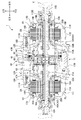
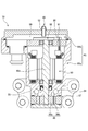
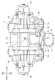
- FIG. 1 is a block diagram showing a schematic configuration of a hybrid vehicle that is an embodiment of a vehicle according to the present invention. It is a longitudinal cross-sectional view of the rear-wheel drive device of one Embodiment.
- FIG. 3 is an enlarged partial sectional view of an upper portion of the rear wheel drive device shown in FIG. 2. It is a perspective view which shows the state in which the vehicle drive device of FIG. 1 was mounted in the flame
- FIG. 7 is a cross-sectional view of the electric oil pump taken along line VII-VII in FIG. 6A. It is a schematic sectional drawing of an electric oil pump. It is a top view of the rear-wheel drive device containing the 1st and 2nd atmosphere communication mechanism. It is a front view of the rear-wheel drive device containing the 1st and 2nd atmosphere communication mechanism. It is a side view of the rear-wheel drive device containing the 1st and 2nd atmosphere communication mechanism. It is a disassembled perspective view of a breather box. It is sectional drawing of a breather box.
- the vehicle drive device uses an electric motor as a drive source for driving wheels, and is used, for example, in a vehicle having a drive system as shown in FIG.
- a vehicle 3 shown in FIG. 1 is a hybrid vehicle having a drive device 6 (hereinafter referred to as a front wheel drive device) in which an internal combustion engine 4 and an electric motor 5 are connected in series at the front portion of the vehicle.
- FIG. 1 reference numeral 8 denotes a control device for controlling the entire vehicle.
- FIG. 2 is a longitudinal sectional view of the entire rear wheel drive device 1
- FIG. 3 is an enlarged partial sectional view of the upper part of FIG.
- reference numeral 11 denotes a case of the rear wheel drive device 1
- the case 11 is arranged on the left and right of the central case 11 ⁇ / b> M so as to sandwich the central case 11 ⁇ / b> M between the central case 11 ⁇ / b> M and the central case 11 ⁇ / b> M.
- axles 10A, 10B for the rear wheels Wr, first and second motors 2A, 2B for driving axles as power sources, rear wheels LWr, RWr, first and second motors 2A,
- the first and second planetary gear type speed reducers 12A and 12B are arranged on the power transmission path to the 2B and decelerate the drive rotation of the first and second electric motors 2A and 2B. 2 shifts) are arranged side by side on the same axis.
- the axle 10A, the first electric motor 2A and the first planetary gear speed reducer 12A drive and control the left rear wheel LWr
- the axle 10B, the second electric motor 2B and the second planetary gear speed reducer 12B drive the right rear wheel RWr.
- the axle 10A, the first electric motor 2A and the first planetary gear speed reducer 12A, and the axle 10B, the second electric motor 2B and the second planetary gear speed reducer 12B are arranged symmetrically in the vehicle width direction in the case 11. Yes.
- the left rear wheel LWr is positioned opposite to the first planetary gear type reduction gear 12A with respect to the first electric motor 2A, and the right rear wheel RWr is also connected to the second planetary gear type reduction gear 12B with respect to the second electric motor 2B.
- the first electric motor 2A and the first planetary gear type speed reducer 12A are arranged in this order from the outer side in the vehicle width direction, and the second electric motor 2B and the second planetary gear type speed reducer 12B are arranged from the outer side in the vehicle width direction.
- positioning in this order 1st and 2nd planetary gear type reduction gears 12A and 12B are arrange
- the side cases 11A and 11B are respectively provided with partition walls 18A and 18B extending radially inward on the central case 11M side. Between the side cases 11A and 11B and the partition walls 18A and 18B, first and first partitions are provided. Two electric motors 2A and 2B are arranged. Further, first and second planetary gear speed reducers 12A and 12B are arranged in a space surrounded by the central case 11M and the partition walls 18A and 18B. As shown in FIG. 2, in this embodiment, the left side case 11A and the center case 11M constitute a first case 11L that houses the first electric motor 2A and the first planetary gear type speed reducer 12A.
- the right side case 11B and the center case 11M constitute a second case 11R that houses the second electric motor 2B and the second planetary gear type speed reducer 12B.
- the first case 11L includes a left reservoir RL that stores oil as a liquid fluid used for lubrication and / or cooling of at least one of the first electric motor 2A and the first planetary gear speed reducer 12A.
- the second case 11R includes a right reservoir RR that stores oil used for lubrication and / or cooling of at least one of the second electric motor 2B and the second planetary gear type speed reducer 12B. As shown in FIG.
- the case 11 is supported by a subframe 13 that is a vehicle skeleton member by mount members 13 a and 13 b that are a pair of support devices, and a vehicle floor panel (not shown) is interposed through the subframe 13. Z)).
- the rear-wheel drive device 1 fixes the mount members 13a and 13b to the boss
- the arrows in FIGS. 2 to 11 indicate the positional relationship when the rear wheel drive device 1 is mounted on the vehicle.
- the rear wheel drive device 1 is provided with a breather device 40 that communicates the inside and the outside of the case 11 so that the air inside is not exposed to the outside through the breather chamber 41 so that the air inside does not become excessively high temperature and pressure. Configured to escape.
- the breather chamber 41 is disposed at the upper part in the vertical direction of the case 11, and includes an outer wall of the central case 11M, a first cylindrical wall 43 extending substantially horizontally in the central case 11M on the left side case 11A side, and a right side case.
- a second cylindrical wall 44 extending substantially horizontally on the 11B side, a left and right dividing wall 45 connecting the inner ends of the first and second cylindrical walls 43, 44, and a left side case 11A of the first cylindrical wall 43.
- the first and second cylindrical walls 43 and 44 and the left and right dividing walls 45 forming the lower surface of the breather chamber 41 are such that the first cylindrical wall 43 is located radially inward from the second cylindrical wall 44 and the left and right dividing walls 45 are
- the third cylindrical wall 44 extends from the inner end portion of the second cylindrical wall 44 to the inner end portion of the first cylindrical wall 43 while being bent while being reduced in diameter, and further extends radially inward to extend substantially horizontally.
- the cylindrical wall 46 is reached.
- the third cylindrical wall 46 is located inside and substantially in the center from both outer ends of the first cylindrical wall 43 and the second cylindrical wall 44.
- baffle plates 47A and 47B are provided in the space between the first cylindrical wall 43 and the outer wall of the central case 11M or the space between the second cylindrical wall 44 and the outer wall of the central case 11M as the first planet. It is fixed so as to be separated from the gear type speed reducer 12A or the second planetary gear type speed reducer 12B.
- an external communication pipe 49 for connecting the breather chamber 41 and the outside is fitted to the central case 11M on the upper surface in the vertical direction of the breather chamber 41.
- the breather chamber side end portion 49a of the external communication pipe 49 is arranged so as to be directed downward in the vertical direction. Therefore, the oil is prevented from being discharged to the outside through the external communication pipe 49.
- the external communication pipe 49 is connected to a hose 161, and together with the hose 161, an atmosphere communication mechanism that communicates the inside of the case 11 and the atmosphere (hereinafter referred to as “atmosphere communication mechanism” refers to both an air communication path and a breather). 160).
- a tip 161 a of the hose 161 is inserted and fixed in a hollow portion having a closed cross section of the subframe 13 (not shown), and communicates with the atmosphere in the subframe 13.
- stators 14A and 14B are fixed to side cases 11A and 11B, respectively, and annular rotors 15A and 15B are rotatably arranged on the inner peripheral sides of the stators 14A and 14B.
- Cylindrical shafts 16A and 16B surrounding the outer periphery of the axles 10A and 10B are coupled to the inner peripheral portions of the rotors 15A and 15B, and the cylindrical shafts 16A and 16B can be relatively rotated coaxially with the axles 10A and 10B.
- the side cases 11A and 11B are supported by end walls 17A and 17B and partition walls 18A and 18B via bearings 19A and 19B.
- the rotational position information of the rotors 15A and 15B is sent to the controller of the first and second electric motors 2A and 2B (not shown).
- Resolvers 20A and 20B are provided for feedback.
- the first and second electric motors 2A and 2B including the stators 14A and 14B and the rotors 15A and 15B have the same diameter, and the rotation axes of the first and second electric motors 2A and 2B are arranged on the same line X (hereinafter referred to as “the same”).
- first and second electric motors 2A and 2B are arranged in mirror symmetry with each other.
- the axle 10A and the cylindrical shaft 16A pass through the first electric motor 2A and extend from both ends of the first electric motor 2A.
- the axle 10B and the cylindrical shaft 16B also penetrate the second electric motor 2B. , Extending from both ends of the second electric motor 2B.
- the first planetary gear type speed reducer 12A disposed on the power transmission path between the left rear wheel LWr and the first motor 2A, and the power transmission path between the right rear wheel RWr and the second motor 2B.
- the second planetary gear speed reducer 12B includes sun gears 21A and 21B, ring gears 24A and 24B positioned on the outer peripheral side of the sun gears 21A and 21B, and a plurality of planetary gears 22A meshed with the sun gears 21A and 21B and the ring gears 24A and 24B. 22B and planetary carriers 23A and 23B that support these planetary gears 22A and 22B.
- the driving forces of the first and second electric motors 2A and 2B are input from the sun gears 21A and 21B, and the reduced driving force is supplied to the planetary gears. It is output to the axles 10A and 10B through the carriers 23A and 23B.
- Sun gears 21A and 21B are formed integrally with cylindrical shafts 16A and 16B.
- the planetary gears 22A and 22B are double pinions having first pinions 26A and 26B having large diameters directly meshed with the sun gears 21A and 21B, and second pinions 27A and 27B having smaller diameters than the first pinions 26A and 26B.
- the first pinions 26A and 26B and the second pinions 27A and 27B are integrally formed in a state of being coaxial and offset in the axial direction.
- the planetary gears 22A and 22B are supported by the pinion shafts 32A and 32B of the planetary carriers 23A and 23B via needle bearings 31A and 31B, and the planetary carriers 23A and 23B have an axially inner end extending radially inward to the axle 10A. 10B and is supported by the partition walls 18A and 18B via bearings 33A and 33B.
- the ring gears 24A and 24B have gear portions 28A and 28B that are meshed with the second pinions 27A and 27B whose inner peripheral surfaces are small in diameter, and small diameters that are smaller than the gear portions 28A and 28B and are opposed to each other at an intermediate position of the case 11.
- the gear portions 28A and 28B face each other in the axial direction with the third cylindrical wall 46 formed at the inner diameter side end of the left and right dividing wall 45 of the central case 11M.
- the outer diameter surfaces of the small diameter portions 29A and 29B are spline-fitted to an inner race 51 of a one-way clutch 50, which will be described later, and the ring gears 24A and 24B are connected to each other so as to rotate integrally with the inner race 51 of the one-way clutch 50. Configured.
- the hydraulic brake 60 is disposed to overlap the first pinion 26B in the radial direction and overlap the second pinion 27B in the axial direction.
- the hydraulic brake 60 includes a plurality of fixed plates 35 that are spline-fitted to the inner peripheral surface of the second cylindrical wall 44 and a plurality of rotary plates 36 that are spline-fitted to the outer peripheral surface of the gear portion 28B of the ring gear 24B.
- the plates 35 and 36 are arranged alternately in the directions, and are fastened and released by an annular piston 37.
- the piston 37 is accommodated in an annular cylinder chamber formed between the left and right dividing walls 45 of the central case 11M and the third cylindrical wall 46, and is provided on the outer peripheral surface of the third cylindrical wall 46.
- the working chamber S into which oil is directly introduced is defined between the left and right dividing walls 45 and the piston 37, and when the pressure of the oil introduced into the working chamber S exceeds the urging force of the elastic member 39, The piston 37 moves forward (to the right), and the fixed plate 35 and the rotating plate 36 are pressed against each other and fastened. When the urging force of the elastic member 39 exceeds the pressure of the oil introduced into the working chamber S, the piston 37 moves backward (leftward movement), and the fixed plate 35 and the rotating plate 36 are separated and released. .
- the hydraulic brake 60 is connected to an electric oil pump 70 (see FIG. 4) as a liquid fluid supply device.
- the fixed plate 35 is supported by the second cylindrical wall 44 extending from the left and right dividing walls 45 of the central case 11M constituting the case 11, while the rotating plate 36 is supported by the gear portion 28B of the ring gear 24B. Therefore, when the plates 35 and 36 are pressed by the piston 37, a braking force is applied to the ring gear 24B by the frictional engagement between the plates 35 and 36, and is fixed. When the fastening by the piston 37 is released from this state, the ring gear 24B is allowed to rotate freely.
- the braking force is also applied to the ring gear 24A when the hydraulic brake 60 is fastened, and the ring gear 24A is fixed when the hydraulic brake 60 is released. Free rotation is allowed.
- a space is secured between the coupling portions 30A and 30B of the ring gears 24A and 24B facing each other in the axial direction, and only power in one direction is transmitted to the ring gears 24A and 24B in the space to transmit power in the other direction.
- a one-way clutch 50 is arranged to be shut off.
- the one-way clutch 50 has a large number of sprags 53 interposed between an inner race 51 and an outer race 52.
- the inner race 51 is connected to the small diameter portions 29A, 29B of the ring gears 24A, 24B by spline fitting. It is configured to rotate integrally.
- the outer race 52 is positioned by the third cylindrical wall 46 and is prevented from rotating.
- the one-way clutch 50 is configured to engage and lock the rotation of the ring gears 24A and 24B when the vehicle 3 moves forward with the power of the first and second electric motors 2A and 2B. More specifically, in the one-way clutch 50, when the rotational power in the forward direction (the rotational direction when the vehicle 3 is advanced) on the first and second electric motors 2A, 2B side is input to the rear wheel Wr side. Is engaged, and the first and second electric motors 2A, 2B are in the non-engaged state when the reverse rotational power is input to the rear wheel Wr, and the forward rotational power is applied to the rear wheel Wr. Is disengaged when the first and second electric motors 2A and 2B are input, and the reverse rotational power on the rear wheel Wr side is input to the first and second electric motors 2A and 2B. Is engaged.
- the one-way clutch 50 and the hydraulic brake 60 are provided in parallel on the power transmission path between the first and second electric motors 2A and 2B and the rear wheel Wr. .
- the hydraulic brake 60 is released, weakly engaged, or engaged by the pressure of oil supplied from the electric oil pump 70 in accordance with the running state of the vehicle and the engaged / disengaged state of the one-way clutch 50. Controlled.
- the one-way clutch 50 is engaged, so that power transmission is possible, but the hydraulic brake Since 60 is controlled to be in a weakly engaged state, the input of forward rotational power from the first and second electric motors 2A, 2B side temporarily decreases, and the one-way clutch 50 becomes disengaged. Even in this case, it becomes possible to prevent power transmission from being disabled between the first and second electric motors 2A and 2B and the rear wheel Wr.
- the one-way clutch 50 is disengaged and the hydraulic brake is controlled to be in a released state. Over-rotation of the first and second electric motors 2A and 2B is prevented.
- the one-way clutch 50 is disengaged, so the hydraulic brake 60 is controlled to be in the engaged state, so that the reverse direction from the first and second electric motors 2A, 2B side is achieved. Rotational power is output to the rear wheel Wr side, or forward rotational power on the rear wheel Wr side is input to the first and second electric motors 2A, 2B.
- the outer peripheral surfaces of the first and second cylindrical walls 43, 44 and the left and right dividing walls 45 of the central case 11 ⁇ / b> M are exposed to the outside at portions other than forming the breather chamber 41.
- a pair of projecting portions 101 and 102 projecting radially from both axial end portions are formed.
- a strainer accommodating chamber 105 is formed as a reservoir for accommodating a strainer 71 described later and storing oil.
- the pair of overhanging portions 101 and 102 forming the strainer accommodating chamber 105 communicate with the through holes 107a and 107b communicating the left reservoir RL and the strainer accommodating chamber 105, and the right reservoir RR and the strainer accommodating chamber 105.
- a through hole (not shown) is formed. Thereby, the left reservoir RL and the right reservoir RR communicate with each other via the strainer storage chamber 105.
- the tip surfaces of the pair of overhanging portions 101, 102, the bottom wall 103, and the upper wall 104 constituting the strainer accommodating chamber 105 form a lid member fixing portion 105b, and are the outer edges of the front opening portion 105a that opens outward. Form.
- the front opening 105a of the strainer accommodating chamber 105 is closed by a lid member 72 to which the electric oil pump 70 is attached.
- the lid member 72 is provided with a case fixing portion 72 a having a substantially square end surface at a position facing the lid member fixing portion 105 b of the case 11.
- the electric oil pump 70 includes a case fixing portion 72 a formed in the lid member 72 and a lid member fixing portion 105 b formed in the front opening 105 a of the strainer accommodating chamber 105.
- the electric oil pump 70 is attached to the lid member 72 so as to be disposed outside the case 11 with respect to the lid member 72 in a closed state in which the lid member 72 is attached to the case 11 and closes the front opening 105a. ing.
- an oil passage forming cover 96 as a flow passage forming member is detachably provided on the inner side of the case with respect to the lid member 72, and is fixed to the lid member 72 with bolts 69. ing.
- the oil passage forming cover 96 together with the lid member 72 defines a part of the oil passage of the hydraulic circuit.
- a low pressure oil passage switching valve 73, a brake oil passage switching valve 74, and a relief valve 84 which will be described later, are arranged in order from the bottom.
- a solenoid valve (not shown) is attached to the opposite side of the lid member 72 from the oil passage forming cover 96, and is energized between the low pressure oil passage switching valve 73 and the brake oil passage switching valve 74 by energization. Connect and shut off the established pilot oil passage.
- the strainer 71 is detachably fixed only to the lid member 72 by having the discharge port 71a inserted into the lid member 72 and being fastened together with a bolt 69 that fastens the oil passage forming cover 96 to the lid member 72. ing.
- the strainer 71 removes foreign matter from the oil sucked from a suction port (not shown) provided on the lower surface thereof, and the oil from which the foreign matter has been removed is sent to the electric oil pump 70.
- the strainer 71 constituting the oil suction path 94 together with the electric oil pump 70 and the lid member 72 extends to the case side from the case fixing portion 72 a of the lid member 72, and the suction port of the strainer 71 Is located in the storage portion of the strainer accommodating chamber 105 in the attached state where the lid member 72 is fixed to the case 11.
- the electric oil pump 70 and the lid member 72 constitute an oil discharge path 95, and the oil pumped from the pumping portion 87 of the electric oil pump 70 described later is interposed between the lid member 72 and the oil path forming cover 96. Send to the formed hydraulic circuit.
- the oil passage forming cover 96 has a brake oil passage working chamber port 108a, which will be described later, formed on the outer peripheral surface of the central case 11M in the strainer accommodating chamber 105, and an oil passage for lubricating the portion to be cooled.
- Two outlet pipes 97a and 97b connected to the cooling / lubricating port 108b are attached.
- the case 11 is formed with a brake oil passage (not shown) that communicates from the working chamber port 108a to the working chamber S of the hydraulic brake 60, and is supplied with oil discharged from the electric oil pump 70. Further, the case 11 includes a front vertical oil passage 109 extending in the vertical direction from the cooling / lubricating port 108b in the front portion of the central case 11M, a left case oil passage 110A branched from the front vertical oil passage 109, and a right case oil passage. 110B. In the left case oil passage 110A, the oil passing through the oil passage 110A cools the cooled portion A1 of the first electric motor 2A (for example, the coil of the stator 14A of the first electric motor 2A).
- the portion to be lubricated A2 (for example, the bearing 19A of the first electric motor 2A) is formed to be lubricated, and is formed to communicate with the left axle oil passage 111A provided on the axle 10A.
- the oil passing through the left axle oil passage 111A is lubricated by the lubricated portion A3 of the first planetary gear speed reducer 12A (for example, the needle bearing 31A of the first planetary gear speed reducer 12A and the gears 21A, 22A, 23A, 24A meshing part etc.) is lubricated.
- the oil that has passed through the oil passage 110B cools the cooled portion B1 of the second electric motor 2B (for example, the coil of the stator 14B of the second electric motor 2B), and the second electric motor It is formed so as to lubricate the lubricated portion B2 of 2B (for example, the bearing 19B of the second electric motor 2B) and communicate with the right axle oil passage 111B provided on the axle 10B.
- the oil passing through the right axle oil passage 111B is lubricated by the lubricated portion B3 of the second planetary gear type reduction gear 12B (for example, the needle bearing 31B of the second planetary gear type reduction gear 12B and the gears 21B, 22B, 24B). Lubricate the meshing part).
- the front vertical oil passage 109, the left case oil passage 110A, and the left axle oil passage 111A formed in the case 11 are the cooled portion A1 and the lubricated portion A2 of the first electric motor 2A, and the first planetary gear type reduction gear.
- the first cooling fluid passage 130A for cooling the lubricated portion A3 of the machine 12A is configured, and the front vertical oil passage 109, the right case oil passage 110B, and the right axle oil passage 111B formed in the case 11 are the second electric motor.
- a second cooling channel 130B for cooling the cooled portion B1 and the lubricated portion B2 of 2B and the lubricated portion B3 of the second planetary gear speed reducer 12B is configured.
- the electric oil pump 70 includes an electric motor unit 85 that houses an electric motor 90 composed of a position sensorless brushless DC motor, and a pressure feeding unit 87 that houses a trochoid pump 86 driven by the electric motor 90. And have.
- the electric oil pump 70 can be operated in at least two modes, a high pressure mode and a low pressure mode, and is controlled by PID control.
- the pressure feeding portion 87 is provided below the oil suction passage 94 and the oil discharge passage 95, and adjusts the discharge amount by rotating the inner rotor 86a connected to the rotating shaft 90a of the electric motor 90 and the outer rotor 86b, while adjusting the discharge amount.
- the oil flowing from 71 into the oil suction path 94 is discharged to the oil discharge path 95.
- the electric motor unit 85 includes a main body accommodating portion 85a in which the electric motor 90 is accommodated, and a control portion accommodating portion 85b that accommodates the control member 88 of the electric motor 90 above the main body accommodating portion 85a.
- the main body accommodating portion 85a and the control portion accommodating portion 85b are communicated with each other through a communication hole 89 formed in the partition member 99, and an electric wire 91 for connecting the electric motor 90 and the control member 88 is disposed in the communication hole 89. Has been.
- the electric oil pump 70 is provided with an atmosphere communication mechanism 98 that communicates the inside and the outside of the electric oil pump 70.
- the air inside the main body housing portion 85 a is connected to the communication hole 89 and the control portion housing portion 85 b so as to keep the internal pressure constant. It is configured to escape to the outside.
- an external communication pipe 92 is fitted on the upper part of the control unit accommodating portion 85b, and a hose 151 is connected to the external communication pipe 92 as shown in FIGS.
- a breather box 140 is attached to the end side. That is, the external communication pipe 92, the hose 151, and the breather box 140 constitute an atmospheric communication mechanism 150 that communicates the inside of the electric motor unit 85 and the atmosphere.
- the atmospheric communication mechanism 150 is independent of the atmospheric communication mechanism 160 described above. Is provided.
- the breather box 140 is fixed to the upper surface of the case 11 so as to be separated from the electric oil pump 70 and disposed at a position higher than the electric oil pump 70. That is, as shown in FIGS. 5 and 11, the strainer accommodating chamber 105 has the first and second electric motors 2 ⁇ / b> A and 2 ⁇ / b> B and the first and second planetary gear speed reducers 12 ⁇ / b> A to collect and store more oil.
- the oil is stored below the virtual horizontal plane H passing through the rotation axis X of 12B, and the electric oil pump 70 is closer to the strainer accommodating chamber 105 than the virtual horizontal plane H in order to improve the oil supply efficiency. It is arranged below.
- the breather box 140 is disposed above the virtual horizontal plane H, so that a difference in height is created between the electric oil pump 70 and the breather box 140, and the function as a breather can be improved. Further, since the breather box 140 is fixed only to the case 11, when the rear wheel drive device 1 is attached to and detached from the subframe 13, the rear wheel drive device 1 and the breather box 140 can be handled integrally. .
- the breather box 140 includes a case member 141 and a lid member 142 that constitute the breather box 140, and is coupled to each other so that a predetermined volume space VS is formed therein.
- the volume space VS communicates with the inside of the electric motor portion 85 of the electric oil pump 70 by connecting the hose 151 to the first pipe portion 141a of the case member 141 serving as one end portion of the passage in the volume space VS.
- the second pipe portion 141b of the case member 141 serving as the other end portion of the passage in the volume space VS communicates with the atmosphere.
- the breather volume chamber of the electric oil pump 70 is constituted by the breather box 140 that is disposed separately from the electric oil pump 70 and disposed at a higher position, so that water can be reliably prevented from entering the atmospheric communication mechanism 98.
- the breather volume chamber can be arranged at a more appropriate position.
- a pore film member 143 sandwiched between the case member 141 and the lid member 142 is disposed.
- the porous membrane member 143 is a member that allows passage of gas and suppresses passage of liquid and solid, and divides the volume space VS into an electric motor part side and an atmosphere side.
- the porous membrane member 143 is disposed in the breather box 140 of the atmospheric communication mechanisms 98 and 150, thereby suppressing intrusion of liquid and solid upstream from the porous membrane member 143 at a position closer to the atmospheric air. To do.
- the breather box that is spaced apart from the electric oil pump 70 and disposed at a position higher than the electric oil pump 70 and has a predetermined volume space VS. 140
- the volume space VS of the breather box 140 communicates with the interior of the electric motor portion 85 of the electric oil pump 70 and communicates with the atmosphere.
- the volume space VS as the breather of the electric oil pump 70 is constituted by the breather box 140 disposed separately from the electric oil pump 70 and disposed at a higher position, so that the water can be surely entered into the atmosphere communication mechanism 98.
- the volume space VS can be arranged at a more appropriate position.
- the breather box 140 is fixed to the case 11, the case 11, the electric oil pump 70, and the breather box 140 can be handled integrally.
- the case 11 includes a strainer storage chamber 105 that stores oil below a virtual horizontal plane H passing through the rotation axis X of the first and second electric motors 2A, 2B or the first and second planetary gear speed reducers 12A, 12B.
- the electric oil pump 70 is disposed below the virtual horizontal plane H, and the breather box 140 is disposed above the virtual horizontal plane H.
- the atmosphere communication passages 98 and 150 including the electric motor unit 85, the breather box 140, and the hose 151 that communicates the electric motor unit 85 and the breather box 140 allow passage of gas and allow passage of liquid and solid.
- a suppressed pore film member 143 is interposed. Thereby, in addition to the suppression of liquid intrusion by the breather box 140 alone, intrusion of liquid and solid by the pore film member 143 can be suppressed.
- the porous membrane member 143 since the porous membrane member 143 is disposed in the breather box 140 in the atmosphere communication path, the porous membrane member 143 can be disposed at a position closer to the atmosphere, and the liquid to the upstream side of the porous membrane member 143 and Solid intrusion can be suppressed.
- the breather box 140 includes a case member 141 and a lid member 142 that are coupled to each other to form the breather box 140.
- the pore membrane member 143 is sandwiched between the case member 141 and the lid member 142, and has a volume space.
- the VS is divided into a motor part side and an atmosphere side.
- the porous membrane member 143 is disposed in the breather box 140 separate from the electric oil pump 70 and between the case member 141 and the lid member 142 constituting the breather box 140. Therefore, the assembly of the porous membrane member 143 is performed. It becomes easy to exchange.
- the electric motor unit 85 includes a main body storage unit 85a in which the electric motor 90 is stored and a control unit storage unit 85b in which the control member 88 of the electric motor 90 is stored.
- the main body storage unit 85a and the control unit storage unit 85b are The communication holes 89 communicate with each other, and electric wires 91 that connect the electric motor 90 and the control member 88 are disposed in the communication holes 89. Thereby, the communication hole 89 can be shared as a space through which the air inside the atmosphere communication mechanism 98 passes and a space for the wiring of the electric wire 91.
- the passenger space / loading space above the floor panel can be expanded.
- the rear wheel drive device 1 of the present embodiment includes an atmosphere communication mechanism 150 that communicates the interior of the electric motor unit 85 of the electric oil pump 70 and the atmosphere, and an atmosphere communication mechanism 160 that communicates the interior of the case 11 and the atmosphere.
- atmosphere communication mechanism 150 that communicates the interior of the electric motor unit 85 of the electric oil pump 70 and the atmosphere
- atmosphere communication mechanism 160 that communicates the interior of the case 11 and the atmosphere.
- the case 11 is supported by the vehicle subframe 13 via mount members 13a and 13b.
- the atmosphere communication mechanism 150 includes a breather box 140 that is spaced apart from the interior of the electric motor unit 85 of the electric oil pump 70 and is higher than the electric motor unit 85 and has a predetermined volume space VS. 140 is fixed to the case 11. Thereby, the atmosphere communication mechanism 150 can be handled integrally with the rear wheel drive device 1. That is, since the breather device 40 of the rear wheel drive device 1 originally attaches and detaches the mount members 13a and 13b when the rear wheel drive device main body is attached to and detached from the subframe 13, the atmosphere communication mechanism 160 is provided with the rear wheel drive device. However, since the electric oil pump 70 is handled integrally with the rear wheel drive device 1, the atmosphere communication mechanism 150 has a great advantage of being handled integrally with the rear wheel drive device 1.
- the atmospheric communication mechanism 150 and the atmospheric communication mechanism 160 only the atmospheric communication mechanism 150 is provided with a porous membrane member 143 that allows passage of gas and suppresses passage of liquid and solid. As a result, the intrusion of liquid and solid by the pore membrane member 143 can be suppressed, and since the atmosphere communication mechanism 150 and the atmosphere communication mechanism 160 are arranged in parallel, the pore membrane member 143 can be minimized. it can.
- the porous membrane member 143 is disposed in the breather box 140, but is not limited thereto, and includes the electric motor unit 85, the breather box 140, and the hose 151 that communicates the electric motor unit 85 and the breather box 140. What is necessary is just to arrange
- the liquid medium supply device is connected to the liquid pressure chamber of the hydraulic pressure connecting / disconnecting means, the cooled portion or the lubricated portion of the power source, or the power transmission mechanism via each medium flow path.
- the liquid medium is supplied to both the cooled portion and the cooled portion that is at least one of the lubricated portion.
- the liquid medium supply device includes the hydraulic chamber and the hydraulic chamber. You may apply to the structure which supplies a liquid medium to either of the to-be-cooled parts.
- the front wheel drive device 6 may be one in which the electric motor 5 is the only drive source without using the internal combustion engine 4.
- the left case 11A and the central case 11M constitute a first case 11L
- the right case 11B and the central case 11M constitute a second case 11R.
- the first case 11L of the present invention accommodates the first electric motor 2A and the first planetary gear type speed reducer 12A and has the left reservoir RL
- the second case 11R is the second electric motor.
- the structure is not limited to this as long as it accommodates 2B and the second planetary gear type speed reducer 12B and has the right reservoir RR.
- the first transmission is on the power transmission path between the left wheel and the first motor 2A, and the power transmission path between the right wheel and the second motor 2B is on.
- the second transmission is configured to be respectively disposed, the present invention may be configured to include the first and second electric motors 2A and 2B without including the first and second transmissions.
- oil is used as the liquid fluid used for cooling and lubrication, but other liquids may be used.
- Rear wheel drive system (vehicle drive system) 2A 1st electric motor (power source) 2B Second electric motor (power source) 3 Vehicle 11 Case (housing) 12A First planetary gear reducer (power transmission mechanism) 12B Second planetary gear type speed reducer (power transmission mechanism) 70 Electric oil pump (liquid fluid supply device) 85 Electric motor part 85a Main body accommodating part 85b Control part accommodating part 86 Trochoid pump (pressure feeding mechanism) 87 Pressure feeding part 88 Control member 89 Communication hole 90 Electric motor 91 Electric wire 98 Atmospheric communication mechanism 105 Strainer accommodation chamber (storage part) 140 Breather box (volume member) 141 Case member (first member) 142 Lid member (second member) 143 Porous membrane member 150 atmospheric communication mechanism (first atmospheric communication mechanism) 151 Hose (Communication member) 160 Atmospheric communication mechanism (second atmospheric communication mechanism) H Virtual horizontal plane LWr Left rear wheel (wheel) RWr Right rear wheel (wheel)
Landscapes
- Engineering & Computer Science (AREA)
- Mechanical Engineering (AREA)
- General Engineering & Computer Science (AREA)
- Combustion & Propulsion (AREA)
- Transportation (AREA)
- Chemical & Material Sciences (AREA)
- Power Engineering (AREA)
- Arrangement Or Mounting Of Propulsion Units For Vehicles (AREA)
- Hybrid Electric Vehicles (AREA)
- Electric Propulsion And Braking For Vehicles (AREA)
- Motor Or Generator Frames (AREA)
- Connection Of Motors, Electrical Generators, Mechanical Devices, And The Like (AREA)
- Cooling, Air Intake And Gas Exhaust, And Fuel Tank Arrangements In Propulsion Units (AREA)
- Arrangement Of Transmissions (AREA)
Abstract
Description
第1態様は、
車両の動力源(例えば、後述の実施形態の第1及び第2電動機2A、2B)と、車両の車輪(例えば、後述の実施形態の左後輪LWr、右後輪RWr)と動力源との動力伝達経路上に配置される動力伝達機構(例えば、後述の実施形態の第1及び第2遊星歯車式減速機12A、12B)と、の少なくとも何れか一方を収容する筐体(例えば、後述の実施形態のケース11)と、
前記筐体に固定されており、前記動力源の被冷却部(例えば、後述の実施形態の被冷却部A1、B1)若しくは被潤滑部(例えば、後述の実施形態の被潤滑部A2、B2)、又は前記動力伝達機構の被冷却部若しくは被潤滑部(例えば、後述の実施形態の被潤滑部A3、B3)の少なくとも何れか一つである被冷潤部に液状媒体を供給するため、電動機(例えば、後述の実施形態の電動機90)によって駆動される液状媒体供給装置(例えば、後述の実施形態の電動オイルポンプ70)と、
を備える車両(例えば、後述の実施形態の車両3)であって、
前記液状媒体供給装置は、前記電動機を収容する電動機部(例えば、後述の実施形態の電動機部85)と、前記電動機によって駆動される圧送機構(例えば、後述の実施形態のトロコイドポンプ86)を収容する圧送部(例えば、後述の実施形態の圧送部87)と、を有し、
前記車両は、前記液状媒体供給装置と離間して該液状媒体供給装置よりも高い位置に配置されるとともに、所定の容積空間(例えば、後述の実施形態の容積空間VS)を有する容積部材(例えば、後述の実施形態のブリーザボックス140)をさらに備え、
前記容積部材の前記容積空間は、前記液状媒体供給装置の前記電動機部の内部に連通するとともに、大気連通することを特徴とする。
車両の車輪(例えば、後述の実施形態の左後輪LWr、右後輪RWr)と動力源(例えば、後述の実施形態の第1及び第2電動機2A、2B)との動力伝達経路上に配置され、前記動力伝達経路を遮断状態と接続状態とに切り替える液圧駆動式の断接手段(例えば、後述の実施形態の油圧ブレーキ60)と、
前記断接手段を収容する筐体(例えば、後述の実施形態のケース11)と、
前記筐体に固定されており、前記断接手段の液圧室(例えば、後述の実施形態の作動室S)に液状媒体を供給するため、電動機(例えば、後述の実施形態の電動機90)によって駆動される液状媒体供給装置(例えば、後述の実施形態の電動オイルポンプ70)と、を備える車両(例えば、後述の実施形態の車両3)であって、
前記液状媒体供給装置は、前記電動機を収容する電動機部(例えば、後述の実施形態の電動機部85)と、前記電動機によって駆動される圧送機構(例えば、後述の実施形態のトロコイドポンプ86)を収容する圧送部(例えば、後述の実施形態の圧送部87)とを有し、
前記車両は、前記液状媒体供給装置と離間して該液状媒体供給装置よりも高い位置に配置されるとともに、所定の容積空間(例えば、後述の実施形態の容積空間VS)を有する容積部材(例えば、後述の実施形態のブリーザボックス140)をさらに備え、
前記容積部材の前記容積空間は、前記液状媒体供給装置の前記電動機部の内部に連通するとともに、大気連通することを特徴とする。
前記容積部材は、前記筐体に固定されることを特徴とする。
前記筐体は、前記動力源又は前記動力伝達機構の回転軸線を通る仮想水平面(例えば、後述の実施形態の仮想水平面H)よりも下方に前記液状媒体を貯留する貯留部(例えば、後述の実施形態のストレーナ収容室105)を有し、
前記液状媒体供給装置は、前記仮想水平面よりも下方に配置され、
前記容積部材は、前記仮想水平面よりも上方に配置されることを特徴とする。
前記電動機部、前記容積部材、及び前記電動機部と前記容積部材とを連通する連通部材(例えば、後述の実施形態におけるホース151)で構成される大気連通路(例えば、後述の実施形態における大気連通機構98、大気連通機構150)には、気体の通過を許容するとともに液体及び固体の通過を抑制する気孔膜部材(例えば、後述の実施形態の気孔膜部材143)が介装されることを特徴とする。
前記気孔膜部材は、前記大気連通路のうち、前記容積部材内に配置されることを特徴とする。
前記容積部材は、相互に結合されて該容積部材を構成する、第1部材(例えば、後述の実施形態におけるケース部材141)及び第2部材(例えば、後述の実施形態における蓋部材142)を有し、
前記気孔膜部材は、前記第1部材と前記第2部材とによって挟持され、前記容積空間を前記電動機部側と大気側とに区画することを特徴とする。
前記電動機部は、前記電動機の本体が収容される本体収容部(例えば、後述の実施形態の本体収容部85a)と、前記電動機の制御部材(例えば、後述の実施形態の制御部材88)を収容する制御部収容部(例えば、後述の実施形態の制御部収容部85b)と、を含み、
前記本体収容部と前記制御部収容部とは、連通穴(例えば、後述の実施形態の連通穴89)によって連通され、
該連通穴には、前記電動機の本体と前記制御部材とを接続する電線(例えば、後述の実施形態の電線91)が配置されることを特徴とする。
前記筐体は、前記車両のフロアパネルよりも下方に配置されることを特徴とする。
車両の動力源(例えば、後述の実施形態の第1及び第2電動機2A、2B)と、前記車両の車輪(例えば、後述の実施形態の左後輪LWr、右後輪RWr)と動力源との動力伝達経路上に配置される動力伝達機構(例えば、後述の実施形態の第1及び第2遊星歯車式減速機12A、12B)の少なくとも何れか一方を収容する筐体(例えば、後述の実施形態のケース11)と、
前記筐体に固定されており、前記動力源の被冷却部(例えば、後述の実施形態の被冷却部A1、B1)若しくは被潤滑部(例えば、後述の実施形態の被潤滑部A2、B2)、又は前記動力伝達機構の被冷却部若しくは被潤滑部(例えば、後述の実施形態の被潤滑部A3、B3)の少なくとも何れか一つである被冷潤部に液状媒体を供給するため、電動機(例えば、後述の実施形態の電動機90)によって駆動される液状媒体供給装置(例えば、後述の実施形態の電動オイルポンプ70)と、を備える車両(例えば、後述の実施形態の車両3)であって、
前記液状媒体供給装置は、前記電動機を収容する電動機部(例えば、後述の実施形態の電動機部85)と、前記電動機によって駆動される圧送機構(例えば、後述の実施形態のトロコイドポンプ86)を収容する圧送部(例えば、後述の実施形態の圧送部87)とを有し、
前記車両は、前記液状媒体供給装置の前記電動機部の内部と大気とを連通する第1大気連通機構(例えば、後述の実施形態の大気連通機構150)と、前記筐体の内部と大気とを連通する第2大気連通機構(例えば、後述の実施形態の大気連通機構160)とを、別個独立に備えることを特徴とする。
前記筐体は、前記車両の骨格部材(例えば、後述の実施形態におけるサブフレーム13)に対し、支持装置(例えば、後述の実施形態のマウント部材13a、13b)を介して支持され、
前記第1大気連通機構は、前記液状媒体供給装置の前記電動機部の内部と離間して該電動機部よりも高い位置に配置されるとともに、所定の容積空間(例えば、後述の実施形態の容積空間VS)を有する容積部材(例えば、後述の実施形態のブリーザボックス140)を有し、
前記容積部材は、前記筐体に固定されることを特徴とする。
前記第1大気連通機構と前記第2大気連通機構とのうち、前記第1大気連通機構のみに気体の通過を許容するとともに液体及び固体の通過を抑制する気孔膜部材(例えば、後述の実施形態の気孔膜部材143)が介装されることを特徴とする。
図1に示す車両3は、内燃機関4と電動機5とが直列に接続された駆動装置6(以下、前輪駆動装置と呼ぶ。)を車両前部に有するハイブリッド車両であり、この前輪駆動装置6の動力がトランスミッション7を介して前輪Wfに伝達される一方で、この前輪駆動装置6と別に車両後部に設けられた駆動装置1(以下、後輪駆動装置と呼ぶ。)の動力が後輪Wr(RWr、LWr)に伝達されるようになっている。前輪駆動装置6の電動機5と後輪駆動装置1の第1及び第2電動機2A、2Bとは、バッテリ9に接続され、バッテリ9からの電力供給と、バッテリ9へのエネルギー回生とが可能となっている。図1中、符号8は車両全体を制御するための制御装置である。
図2は、後輪駆動装置1の全体の縦断面図を示すものであり、図3は、図2の上部部分拡大断面図である。同図において、符号11は、後輪駆動装置1のケースであり、ケース11は、車幅方向略中央部に配置される中央ケース11Mと、中央ケース11Mを挟むように中央ケース11Mの左右に配置される側方ケース11A、11Bと、から構成され、全体が略円筒状に形成される。ケース11の内部には、後輪Wr用の車軸10A、10Bと、動力源として車軸駆動用の第1及び第2電動機2A、2Bと、後輪LWr、RWrと第1及び第2電動機2A、2Bとの動力伝達経路上に配置され、この第1及び第2電動機2A、2Bの駆動回転を減速する動力伝達機構としての第1及び第2遊星歯車式減速機12A、12B(第1及び第2変速)とが、同一軸線上にそれぞれ並んで配置されている。この車軸10A、第1電動機2A及び第1遊星歯車式減速機12Aは左後輪LWrを駆動制御し、車軸10B、第2電動機2B及び第2遊星歯車式減速機12Bは右後輪RWrを駆動制御する。車軸10A、第1電動機2A及び第1遊星歯車式減速機12Aと、車軸10B、第2電動機2B及び第2遊星歯車式減速機12Bは、ケース11内で車幅方向に左右対称に配置されている。左後輪LWrは、第1電動機2Aに対して第1遊星歯車式減速機12Aと反対側に位置し、右後輪RWrも、第2電動機2Bに対して第2遊星歯車式減速機12Bと反対側に位置する。また、第1電動機2Aと第1遊星歯車式減速機12Aとは車幅方向外側からこの順序で配置され、且つ、第2電動機2Bと第2遊星歯車式減速機12Bとは車幅方向外側からこの順序で配置されることにより、第1及び第2遊星歯車式減速機12A、12Bは、第1及び第2電動機2A、2Bの間に配置される。
また、電動オイルポンプ70及び蓋部材72はオイル吐出路95を構成しており、後述する電動オイルポンプ70の圧送部87から圧送されたオイルを蓋部材72と油路形成カバー96との間に形成された油圧回路へと送る。
本実施形態では、気孔膜部材143はブリーザボックス140内に配置されているが、これに限らず、電動機部85、ブリーザボックス140、及び電動機部85とブリーザボックス140とを連通するホース151で構成される大気連通路のいずれかに配置されればよい。
2A 第1電動機(動力源)
2B 第2電動機(動力源)
3 車両
11 ケース(筐体)
12A 第1遊星歯車式減速機(動力伝達機構)
12B 第2遊星歯車式減速機(動力伝達機構)
70 電動オイルポンプ(液状流体供給装置)
85 電動機部
85a 本体収容部
85b 制御部収容部
86 トロコイドポンプ(圧送機構)
87 圧送部
88 制御部材
89 連通穴
90 電動機
91 電線
98 大気連通機構
105 ストレーナ収容室(貯留部)
140 ブリーザボックス(容積部材)
141 ケース部材(第1部材)
142 蓋部材(第2部材)
143 気孔膜部材
150 大気連通機構(第1大気連通機構)
151 ホース(連通部材)
160 大気連通機構(第2大気連通機構)
H 仮想水平面
LWr 左後輪(車輪)
RWr 右後輪(車輪)
Claims (12)
- 車両の動力源と、車両の車輪と動力源との動力伝達経路上に配置される動力伝達機構と、の少なくとも何れか一方を収容する筐体と、
前記筐体に固定されており、前記動力源の被冷却部若しくは被潤滑部、又は前記動力伝達機構の被冷却部若しくは被潤滑部の少なくとも何れか一つである被冷潤部に液状媒体を供給するため、電動機によって駆動される液状媒体供給装置と、を備える車両であって、
前記液状媒体供給装置は、前記電動機を収容する電動機部と、前記電動機によって駆動される圧送機構を収容する圧送部と、を有し、
前記車両は、前記液状媒体供給装置と離間して該液状媒体供給装置よりも高い位置に配置されるとともに、所定の容積空間を有する容積部材をさらに備え、
前記容積部材の前記容積空間は、前記液状媒体供給装置の前記電動機部の内部に連通するとともに、大気連通することを特徴とする車両。 - 車両の車輪と動力源との動力伝達経路上に配置され、前記動力伝達経路を遮断状態と接続状態とに切り替える液圧駆動式の断接手段と、
前記断接手段を収容する筐体と、
前記筐体に固定されており、前記断接手段の液圧室に液状媒体を供給するため、電動機によって駆動される液状媒体供給装置と、
を備える車両であって、
前記液状媒体供給装置は、前記電動機を収容する電動機部と、前記電動機によって駆動される圧送機構を収容する圧送部と、を有し、
前記車両は、前記液状媒体供給装置と離間して該液状媒体供給装置よりも高い位置に配置されるとともに、所定の容積空間を有する容積部材をさらに備え、
前記容積部材の前記容積空間は、前記液状媒体供給装置の前記電動機部の内部に連通するとともに、大気連通することを特徴とする車両。 - 前記容積部材は、前記筐体に固定されることを特徴とする請求項1又は2に記載の車両。
- 前記筐体は、前記動力源又は前記動力伝達機構の回転軸線を通る仮想水平面よりも下方に前記液状媒体を貯留する貯留部を有し、
前記液状媒体供給装置は、前記仮想水平面よりも下方に配置され、
前記容積部材は、前記仮想水平面よりも上方に配置されることを特徴とする請求項3に記載の車両。 - 前記電動機部、前記容積部材、及び前記電動機部と前記容積部材とを連通する連通部材で構成される大気連通路には、気体の通過を許容するとともに液体及び固体の通過を抑制する気孔膜部材が介装されることを特徴とする請求項1~4のいずれか1項に記載の車両。
- 前記気孔膜部材は、前記大気連通路のうち、前記容積部材内に配置されることを特徴とする請求項5に記載の車両。
- 前記容積部材は、相互に結合されて該容積部材を構成する、第1部材及び第2部材を有し、
前記気孔膜部材は、前記第1部材と前記第2部材とによって挟持され、前記容積空間を前記電動機部側と大気側とに区画することを特徴とする請求項6に記載の車両。 - 前記電動機部は、前記電動機の本体が収容される本体収容部と、前記電動機の制御部材を収容する制御部収容部と、を含み、
前記本体収容部と前記制御部収容部とは、連通穴によって連通され、
該連通穴には、前記電動機の本体と前記制御部材とを接続する電線が配置されることを特徴とする請求項1~7のいずれか1項に記載の車両。 - 前記筐体は、前記車両のフロアパネルよりも下方に配置されることを特徴とする請求項1~8のいずれか1項に記載の車両。
- 車両の動力源と、車両の車輪と動力源との動力伝達経路上に配置される動力伝達機構と、の少なくとも何れか一方を収容する筐体と、
前記筐体に固定されており、前記動力源の被冷却部若しくは被潤滑部、又は前記動力伝達機構の被冷却部若しくは被潤滑部の少なくとも何れか一つである被冷潤部に液状媒体を供給するため、電動機によって駆動される液状媒体供給装置と、を備える車両であって、
前記液状媒体供給装置は、前記電動機を収容する電動機部と、前記電動機によって駆動される圧送機構を収容する圧送部と、を有し、
前記車両は、前記液状媒体供給装置の前記電動機部の内部と大気とを連通する第1大気連通機構と、前記筐体の内部と大気とを連通する第2大気連通機構とを、別個独立に備えることを特徴とする車両。 - 前記筐体は、前記車両の骨格部材に対し、支持装置を介して支持され、
前記第1大気連通機構は、前記液状媒体供給装置の前記電動機部の内部と離間して該電動機部よりも高い位置に配置されるとともに、所定の容積空間を有する容積部材を有し、
前記容積部材は、前記筐体に固定されることを特徴とする請求項10に記載の車両。 - 前記第1大気連通機構と前記第2大気連通機構とのうち、前記第1大気連通機構のみに気体の通過を許容するとともに液体及び固体の通過を抑制する気孔膜部材が介装されることを特徴とする請求項10又は11に記載の車両。
Priority Applications (7)
| Application Number | Priority Date | Filing Date | Title |
|---|---|---|---|
| US15/100,465 US9809186B2 (en) | 2013-12-02 | 2014-12-02 | Vehicle |
| KR1020167014424A KR101953448B1 (ko) | 2013-12-02 | 2014-12-02 | 차량 |
| CN201480064774.9A CN105829157B (zh) | 2013-12-02 | 2014-12-02 | 车辆 |
| MYPI2016701977A MY188847A (en) | 2013-12-02 | 2014-12-02 | Vehicle |
| EP14868230.5A EP3078534B1 (en) | 2013-12-02 | 2014-12-02 | Vehicle |
| CA2931868A CA2931868A1 (en) | 2013-12-02 | 2014-12-02 | Vehicle |
| JP2015551518A JP5933856B2 (ja) | 2013-12-02 | 2014-12-02 | 車両 |
Applications Claiming Priority (2)
| Application Number | Priority Date | Filing Date | Title |
|---|---|---|---|
| JP2013249618 | 2013-12-02 | ||
| JP2013-249618 | 2013-12-02 |
Publications (1)
| Publication Number | Publication Date |
|---|---|
| WO2015083700A1 true WO2015083700A1 (ja) | 2015-06-11 |
Family
ID=53273462
Family Applications (1)
| Application Number | Title | Priority Date | Filing Date |
|---|---|---|---|
| PCT/JP2014/081868 Ceased WO2015083700A1 (ja) | 2013-12-02 | 2014-12-02 | 車両 |
Country Status (8)
| Country | Link |
|---|---|
| US (1) | US9809186B2 (ja) |
| EP (1) | EP3078534B1 (ja) |
| JP (1) | JP5933856B2 (ja) |
| KR (1) | KR101953448B1 (ja) |
| CN (1) | CN105829157B (ja) |
| CA (1) | CA2931868A1 (ja) |
| MY (1) | MY188847A (ja) |
| WO (1) | WO2015083700A1 (ja) |
Cited By (8)
| Publication number | Priority date | Publication date | Assignee | Title |
|---|---|---|---|---|
| JP2017150606A (ja) * | 2016-02-25 | 2017-08-31 | 本田技研工業株式会社 | ブリーザ装置 |
| WO2018008160A1 (ja) * | 2016-07-08 | 2018-01-11 | Gkn ドライブライン ジャパン株式会社 | 動力伝達装置 |
| JP2021143660A (ja) * | 2020-03-13 | 2021-09-24 | 日本電産トーソク株式会社 | 電動ポンプ |
| US11338660B2 (en) * | 2017-11-10 | 2022-05-24 | Dana Heavy Vehicle Systems Group, Llc | Modular head assembly for an electric axle |
| JP7253383B2 (ja) | 2016-05-09 | 2023-04-06 | ニコラ・コーポレーション | モータ歯車箱組立体 |
| JP7414105B1 (ja) | 2022-09-27 | 2024-01-16 | いすゞ自動車株式会社 | モータの組付方法 |
| US12460716B1 (en) * | 2024-05-01 | 2025-11-04 | Schaeffler Technologies AG & Co. KG | Force lubricated differential for electric vehicle |
| WO2026048147A1 (ja) * | 2024-08-28 | 2026-03-05 | ジヤトコ株式会社 | ユニット |
Families Citing this family (21)
| Publication number | Priority date | Publication date | Assignee | Title |
|---|---|---|---|---|
| HUE053350T2 (hu) * | 2013-03-15 | 2021-06-28 | Linamar Corp | Hibridtengelyes részegység gépjármûhöz |
| US9561713B2 (en) * | 2014-12-28 | 2017-02-07 | Skylar Netherland | Systems and methods for a mounting device for vehicles |
| CN104943633B (zh) * | 2015-06-25 | 2017-09-05 | 安徽江淮汽车集团股份有限公司 | 一种汽车零部件用通气结构 |
| DE102016218774A1 (de) | 2016-09-28 | 2018-03-29 | Bayerische Motoren Werke Aktiengesellschaft | Kraftfahrzeug mit einem Kraftfahrzeuggetriebegehäuse mit Entlüftung |
| DE102016220414B4 (de) * | 2016-10-18 | 2026-01-22 | Audi Ag | Fahrzeugachse für ein Kraftfahrzeug |
| EP3667876B1 (en) * | 2017-11-17 | 2022-11-23 | Aisin Corporation | Vehicle drive device |
| DE102017223491B4 (de) * | 2017-12-21 | 2025-12-31 | Audi Ag | Elektromaschinenanordnung |
| DE102018215934A1 (de) * | 2018-09-19 | 2020-03-19 | ZF Drivetech (Suzhou) Co.Ltd. | Achsantrieb |
| DE102019126269A1 (de) * | 2019-09-30 | 2021-04-01 | Audi Ag | Druckausgleichsanordnung |
| JP7206182B2 (ja) * | 2019-12-26 | 2023-01-17 | 株式会社クボタ | 電動作業車 |
| WO2021137290A1 (ja) * | 2019-12-30 | 2021-07-08 | ジヤトコ株式会社 | 動力伝達装置 |
| DE102021111907A1 (de) | 2021-05-07 | 2022-11-10 | Bayerische Motoren Werke Aktiengesellschaft | Druckausgleichsanordnung sowie elektrische Maschine |
| JP7593912B2 (ja) * | 2021-11-11 | 2024-12-03 | トヨタ自動車株式会社 | 車両の潤滑構造 |
| KR20240040877A (ko) | 2022-09-22 | 2024-03-29 | 엘에스엠트론 주식회사 | 캐빈형 농작업차 |
| US12312091B2 (en) | 2022-10-06 | 2025-05-27 | Archer Aviation Inc. | Systems and methods for improved gearboxes for evtol aircraft |
| US11787551B1 (en) | 2022-10-06 | 2023-10-17 | Archer Aviation, Inc. | Vertical takeoff and landing aircraft electric engine configuration |
| US12227300B2 (en) | 2022-10-06 | 2025-02-18 | Archer Aviation Inc. | Systems and methods for oil maintenance in gearboxes for eVTOL aircraft |
| JP2024096587A (ja) * | 2023-01-04 | 2024-07-17 | 株式会社クボタ | 作業機 |
| CN116455119B (zh) * | 2023-04-19 | 2023-10-31 | 扬州市华天电机有限公司 | 一种防护型直流电机 |
| US12594828B2 (en) * | 2023-10-30 | 2026-04-07 | Kubota Corporation | Electric work vehicle |
| CN120792487B (zh) * | 2025-09-10 | 2025-12-26 | 安徽维德动力科技股份有限公司 | 一种紧凑型动力系统及电动叉车 |
Citations (7)
| Publication number | Priority date | Publication date | Assignee | Title |
|---|---|---|---|---|
| JPS5934463U (ja) * | 1981-12-14 | 1984-03-03 | 株式会社ボッシュオートモーティブ システム | モ−タの呼吸装置 |
| JPS626487U (ja) | 1985-06-26 | 1987-01-16 | ||
| JPH0412646A (ja) * | 1990-04-27 | 1992-01-17 | Taiyo Ltd | 液浸型電動機 |
| JPH0515656U (ja) * | 1991-08-02 | 1993-02-26 | アスモ株式会社 | モータの呼吸装置 |
| JPH0728272U (ja) * | 1993-10-29 | 1995-05-23 | エヌオーケー株式会社 | ブリーザ |
| JP2004353537A (ja) * | 2003-05-28 | 2004-12-16 | Aisin Seiki Co Ltd | 電動ポンプ |
| JP2012257347A (ja) * | 2011-06-07 | 2012-12-27 | Honda Motor Co Ltd | 車両用駆動装置 |
Family Cites Families (14)
| Publication number | Priority date | Publication date | Assignee | Title |
|---|---|---|---|---|
| JPS626487A (ja) | 1985-07-01 | 1987-01-13 | Nec Corp | 複数デ−タビツト構成のメモリic |
| JP2589333Y2 (ja) * | 1992-08-07 | 1999-01-27 | 千住スプリンクラー株式会社 | スプリンクラーヘッド |
| JP3600320B2 (ja) * | 1995-08-10 | 2004-12-15 | 愛知機械工業株式会社 | 電気自動車用パワートレーンのエアブリーザー構造 |
| DE602004023556D1 (de) * | 2003-05-28 | 2009-11-26 | Aisin Seiki | Elektrisch angetriebene Pumpe |
| US7462963B2 (en) * | 2004-11-30 | 2008-12-09 | Nissan Motor Co., Ltd. | Motor cooling device and cooling method |
| US20080099258A1 (en) * | 2006-10-26 | 2008-05-01 | Berhan Michael T | Vented sealed housing assembly for vehicle powertrain |
| WO2009016884A1 (ja) * | 2007-07-30 | 2009-02-05 | Hitachi Construction Machinery Co., Ltd. | 作業車両の走行駆動装置 |
| JP5032515B2 (ja) * | 2009-01-28 | 2012-09-26 | 日立建機株式会社 | 走行減速機用潤滑油の冷却装置 |
| JP5414636B2 (ja) * | 2010-08-24 | 2014-02-12 | 本田技研工業株式会社 | 車両用駆動装置 |
| US8485289B2 (en) * | 2011-02-24 | 2013-07-16 | Deere & Company | Air pressure regulated axle sump |
| US8727052B2 (en) * | 2011-02-24 | 2014-05-20 | Deere & Company | Dry axle center section |
| US9266423B2 (en) * | 2011-06-07 | 2016-02-23 | Honda Motor Co., Ltd. | Vehicle driving device |
| JP5378487B2 (ja) * | 2011-11-17 | 2013-12-25 | 本田技研工業株式会社 | ブリーザ装置 |
| JP5638050B2 (ja) * | 2012-10-05 | 2014-12-10 | 本田技研工業株式会社 | 車両用駆動装置 |
-
2014
- 2014-12-02 MY MYPI2016701977A patent/MY188847A/en unknown
- 2014-12-02 US US15/100,465 patent/US9809186B2/en active Active
- 2014-12-02 EP EP14868230.5A patent/EP3078534B1/en not_active Not-in-force
- 2014-12-02 JP JP2015551518A patent/JP5933856B2/ja active Active
- 2014-12-02 KR KR1020167014424A patent/KR101953448B1/ko not_active Expired - Fee Related
- 2014-12-02 WO PCT/JP2014/081868 patent/WO2015083700A1/ja not_active Ceased
- 2014-12-02 CA CA2931868A patent/CA2931868A1/en not_active Abandoned
- 2014-12-02 CN CN201480064774.9A patent/CN105829157B/zh not_active Expired - Fee Related
Patent Citations (7)
| Publication number | Priority date | Publication date | Assignee | Title |
|---|---|---|---|---|
| JPS5934463U (ja) * | 1981-12-14 | 1984-03-03 | 株式会社ボッシュオートモーティブ システム | モ−タの呼吸装置 |
| JPS626487U (ja) | 1985-06-26 | 1987-01-16 | ||
| JPH0412646A (ja) * | 1990-04-27 | 1992-01-17 | Taiyo Ltd | 液浸型電動機 |
| JPH0515656U (ja) * | 1991-08-02 | 1993-02-26 | アスモ株式会社 | モータの呼吸装置 |
| JPH0728272U (ja) * | 1993-10-29 | 1995-05-23 | エヌオーケー株式会社 | ブリーザ |
| JP2004353537A (ja) * | 2003-05-28 | 2004-12-16 | Aisin Seiki Co Ltd | 電動ポンプ |
| JP2012257347A (ja) * | 2011-06-07 | 2012-12-27 | Honda Motor Co Ltd | 車両用駆動装置 |
Non-Patent Citations (1)
| Title |
|---|
| See also references of EP3078534A4 |
Cited By (17)
| Publication number | Priority date | Publication date | Assignee | Title |
|---|---|---|---|---|
| CN107120415A (zh) * | 2016-02-25 | 2017-09-01 | 本田技研工业株式会社 | 通气装置 |
| US10030759B2 (en) | 2016-02-25 | 2018-07-24 | Honda Motor Co., Ltd. | Breather device |
| CN107120415B (zh) * | 2016-02-25 | 2019-08-13 | 本田技研工业株式会社 | 通气装置 |
| JP2017150606A (ja) * | 2016-02-25 | 2017-08-31 | 本田技研工業株式会社 | ブリーザ装置 |
| JP7253383B2 (ja) | 2016-05-09 | 2023-04-06 | ニコラ・コーポレーション | モータ歯車箱組立体 |
| WO2018008160A1 (ja) * | 2016-07-08 | 2018-01-11 | Gkn ドライブライン ジャパン株式会社 | 動力伝達装置 |
| WO2018008141A1 (ja) * | 2016-07-08 | 2018-01-11 | Gkn ドライブライン ジャパン株式会社 | 動力伝達装置 |
| JPWO2018008160A1 (ja) * | 2016-07-08 | 2019-02-28 | Gknドライブラインジャパン株式会社 | 動力伝達装置 |
| US10828977B2 (en) | 2016-07-08 | 2020-11-10 | Gkn Automotive Ltd. | Power transmission device |
| US11207966B2 (en) | 2016-07-08 | 2021-12-28 | Gkn Automotive Limited | Power transmission device |
| US11338660B2 (en) * | 2017-11-10 | 2022-05-24 | Dana Heavy Vehicle Systems Group, Llc | Modular head assembly for an electric axle |
| JP2021143660A (ja) * | 2020-03-13 | 2021-09-24 | 日本電産トーソク株式会社 | 電動ポンプ |
| JP7463775B2 (ja) | 2020-03-13 | 2024-04-09 | ニデックパワートレインシステムズ株式会社 | 電動ポンプ |
| JP7414105B1 (ja) | 2022-09-27 | 2024-01-16 | いすゞ自動車株式会社 | モータの組付方法 |
| JP2024047808A (ja) * | 2022-09-27 | 2024-04-08 | いすゞ自動車株式会社 | モータの組付方法 |
| US12460716B1 (en) * | 2024-05-01 | 2025-11-04 | Schaeffler Technologies AG & Co. KG | Force lubricated differential for electric vehicle |
| WO2026048147A1 (ja) * | 2024-08-28 | 2026-03-05 | ジヤトコ株式会社 | ユニット |
Also Published As
| Publication number | Publication date |
|---|---|
| EP3078534A1 (en) | 2016-10-12 |
| JP5933856B2 (ja) | 2016-06-15 |
| MY188847A (en) | 2022-01-09 |
| EP3078534A4 (en) | 2017-07-26 |
| KR101953448B1 (ko) | 2019-02-28 |
| EP3078534B1 (en) | 2019-08-28 |
| US9809186B2 (en) | 2017-11-07 |
| CN105829157A (zh) | 2016-08-03 |
| US20160297385A1 (en) | 2016-10-13 |
| CN105829157B (zh) | 2019-05-10 |
| JPWO2015083700A1 (ja) | 2017-03-16 |
| CA2931868A1 (en) | 2015-06-11 |
| KR20160093007A (ko) | 2016-08-05 |
Similar Documents
| Publication | Publication Date | Title |
|---|---|---|
| JP5933856B2 (ja) | 車両 | |
| KR101520215B1 (ko) | 차량용 구동 장치 | |
| JP5638050B2 (ja) | 車両用駆動装置 | |
| JP5487317B2 (ja) | 車両用駆動装置 | |
| JP5509289B2 (ja) | 車両用駆動装置 | |
| JP5398788B2 (ja) | 車両用駆動装置 | |
| JP2020121716A (ja) | 動力伝達装置 | |
| JP5647946B2 (ja) | 車両用駆動装置 | |
| JP5771663B2 (ja) | 車両用駆動装置 | |
| JP5449279B2 (ja) | 車両用駆動装置 | |
| JP6228841B2 (ja) | 動力装置 | |
| JP6163423B2 (ja) | 動力装置 | |
| JP6200790B2 (ja) | 車両用駆動装置 | |
| JP5732305B2 (ja) | 車両用駆動装置 | |
| JP5581362B2 (ja) | 車両用駆動装置 | |
| JP6232268B2 (ja) | 車両用駆動装置 | |
| JP5509288B2 (ja) | 車両用駆動装置 | |
| JP6228825B2 (ja) | 動力装置 |
Legal Events
| Date | Code | Title | Description |
|---|---|---|---|
| 121 | Ep: the epo has been informed by wipo that ep was designated in this application |
Ref document number: 14868230 Country of ref document: EP Kind code of ref document: A1 |
|
| ENP | Entry into the national phase |
Ref document number: 2015551518 Country of ref document: JP Kind code of ref document: A |
|
| ENP | Entry into the national phase |
Ref document number: 2931868 Country of ref document: CA |
|
| ENP | Entry into the national phase |
Ref document number: 20167014424 Country of ref document: KR Kind code of ref document: A |
|
| WWE | Wipo information: entry into national phase |
Ref document number: 15100465 Country of ref document: US |
|
| NENP | Non-entry into the national phase |
Ref country code: DE |
|
| REEP | Request for entry into the european phase |
Ref document number: 2014868230 Country of ref document: EP |
|
| WWE | Wipo information: entry into national phase |
Ref document number: 2014868230 Country of ref document: EP |