WO2015083790A1 - 二次電池用セパレータ及び二次電池 - Google Patents
二次電池用セパレータ及び二次電池 Download PDFInfo
- Publication number
- WO2015083790A1 WO2015083790A1 PCT/JP2014/082118 JP2014082118W WO2015083790A1 WO 2015083790 A1 WO2015083790 A1 WO 2015083790A1 JP 2014082118 W JP2014082118 W JP 2014082118W WO 2015083790 A1 WO2015083790 A1 WO 2015083790A1
- Authority
- WO
- WIPO (PCT)
- Prior art keywords
- separator
- fluoropolymer
- porous membrane
- composite porous
- mass
- Prior art date
- Legal status (The legal status is an assumption and is not a legal conclusion. Google has not performed a legal analysis and makes no representation as to the accuracy of the status listed.)
- Ceased
Links
Classifications
-
- C—CHEMISTRY; METALLURGY
- C08—ORGANIC MACROMOLECULAR COMPOUNDS; THEIR PREPARATION OR CHEMICAL WORKING-UP; COMPOSITIONS BASED THEREON
- C08F—MACROMOLECULAR COMPOUNDS OBTAINED BY REACTIONS ONLY INVOLVING CARBON-TO-CARBON UNSATURATED BONDS
- C08F214/00—Copolymers of compounds having one or more unsaturated aliphatic radicals, each having only one carbon-to-carbon double bond, and at least one being terminated by a halogen
- C08F214/18—Monomers containing fluorine
- C08F214/26—Tetrafluoroethene
- C08F214/262—Tetrafluoroethene with fluorinated vinyl ethers
-
- H—ELECTRICITY
- H01—ELECTRIC ELEMENTS
- H01M—PROCESSES OR MEANS, e.g. BATTERIES, FOR THE DIRECT CONVERSION OF CHEMICAL ENERGY INTO ELECTRICAL ENERGY
- H01M50/00—Constructional details or processes of manufacture of the non-active parts of electrochemical cells other than fuel cells, e.g. hybrid cells
- H01M50/40—Separators; Membranes; Diaphragms; Spacing elements inside cells
- H01M50/409—Separators, membranes or diaphragms characterised by the material
- H01M50/411—Organic material
- H01M50/414—Synthetic resins, e.g. thermoplastics or thermosetting resins
- H01M50/417—Polyolefins
-
- C—CHEMISTRY; METALLURGY
- C08—ORGANIC MACROMOLECULAR COMPOUNDS; THEIR PREPARATION OR CHEMICAL WORKING-UP; COMPOSITIONS BASED THEREON
- C08F—MACROMOLECULAR COMPOUNDS OBTAINED BY REACTIONS ONLY INVOLVING CARBON-TO-CARBON UNSATURATED BONDS
- C08F214/00—Copolymers of compounds having one or more unsaturated aliphatic radicals, each having only one carbon-to-carbon double bond, and at least one being terminated by a halogen
- C08F214/18—Monomers containing fluorine
- C08F214/22—Vinylidene fluoride
-
- H—ELECTRICITY
- H01—ELECTRIC ELEMENTS
- H01M—PROCESSES OR MEANS, e.g. BATTERIES, FOR THE DIRECT CONVERSION OF CHEMICAL ENERGY INTO ELECTRICAL ENERGY
- H01M10/00—Secondary cells; Manufacture thereof
- H01M10/05—Accumulators with non-aqueous electrolyte
- H01M10/052—Li-accumulators
- H01M10/0525—Rocking-chair batteries, i.e. batteries with lithium insertion or intercalation in both electrodes; Lithium-ion batteries
-
- H—ELECTRICITY
- H01—ELECTRIC ELEMENTS
- H01M—PROCESSES OR MEANS, e.g. BATTERIES, FOR THE DIRECT CONVERSION OF CHEMICAL ENERGY INTO ELECTRICAL ENERGY
- H01M50/00—Constructional details or processes of manufacture of the non-active parts of electrochemical cells other than fuel cells, e.g. hybrid cells
- H01M50/40—Separators; Membranes; Diaphragms; Spacing elements inside cells
- H01M50/409—Separators, membranes or diaphragms characterised by the material
- H01M50/411—Organic material
- H01M50/414—Synthetic resins, e.g. thermoplastics or thermosetting resins
- H01M50/426—Fluorocarbon polymers
-
- H—ELECTRICITY
- H01—ELECTRIC ELEMENTS
- H01M—PROCESSES OR MEANS, e.g. BATTERIES, FOR THE DIRECT CONVERSION OF CHEMICAL ENERGY INTO ELECTRICAL ENERGY
- H01M50/00—Constructional details or processes of manufacture of the non-active parts of electrochemical cells other than fuel cells, e.g. hybrid cells
- H01M50/40—Separators; Membranes; Diaphragms; Spacing elements inside cells
- H01M50/409—Separators, membranes or diaphragms characterised by the material
- H01M50/443—Particulate material
-
- H—ELECTRICITY
- H01—ELECTRIC ELEMENTS
- H01M—PROCESSES OR MEANS, e.g. BATTERIES, FOR THE DIRECT CONVERSION OF CHEMICAL ENERGY INTO ELECTRICAL ENERGY
- H01M50/00—Constructional details or processes of manufacture of the non-active parts of electrochemical cells other than fuel cells, e.g. hybrid cells
- H01M50/40—Separators; Membranes; Diaphragms; Spacing elements inside cells
- H01M50/409—Separators, membranes or diaphragms characterised by the material
- H01M50/446—Composite material consisting of a mixture of organic and inorganic materials
-
- H—ELECTRICITY
- H01—ELECTRIC ELEMENTS
- H01M—PROCESSES OR MEANS, e.g. BATTERIES, FOR THE DIRECT CONVERSION OF CHEMICAL ENERGY INTO ELECTRICAL ENERGY
- H01M50/00—Constructional details or processes of manufacture of the non-active parts of electrochemical cells other than fuel cells, e.g. hybrid cells
- H01M50/40—Separators; Membranes; Diaphragms; Spacing elements inside cells
- H01M50/409—Separators, membranes or diaphragms characterised by the material
- H01M50/449—Separators, membranes or diaphragms characterised by the material having a layered structure
-
- H—ELECTRICITY
- H01—ELECTRIC ELEMENTS
- H01M—PROCESSES OR MEANS, e.g. BATTERIES, FOR THE DIRECT CONVERSION OF CHEMICAL ENERGY INTO ELECTRICAL ENERGY
- H01M50/00—Constructional details or processes of manufacture of the non-active parts of electrochemical cells other than fuel cells, e.g. hybrid cells
- H01M50/40—Separators; Membranes; Diaphragms; Spacing elements inside cells
- H01M50/409—Separators, membranes or diaphragms characterised by the material
- H01M50/449—Separators, membranes or diaphragms characterised by the material having a layered structure
- H01M50/451—Separators, membranes or diaphragms characterised by the material having a layered structure comprising layers of only organic material and layers containing inorganic material
-
- H—ELECTRICITY
- H01—ELECTRIC ELEMENTS
- H01M—PROCESSES OR MEANS, e.g. BATTERIES, FOR THE DIRECT CONVERSION OF CHEMICAL ENERGY INTO ELECTRICAL ENERGY
- H01M50/00—Constructional details or processes of manufacture of the non-active parts of electrochemical cells other than fuel cells, e.g. hybrid cells
- H01M50/40—Separators; Membranes; Diaphragms; Spacing elements inside cells
- H01M50/489—Separators, membranes, diaphragms or spacing elements inside the cells, characterised by their physical properties, e.g. swelling degree, hydrophilicity or shut down properties
- H01M50/491—Porosity
-
- H—ELECTRICITY
- H01—ELECTRIC ELEMENTS
- H01M—PROCESSES OR MEANS, e.g. BATTERIES, FOR THE DIRECT CONVERSION OF CHEMICAL ENERGY INTO ELECTRICAL ENERGY
- H01M50/00—Constructional details or processes of manufacture of the non-active parts of electrochemical cells other than fuel cells, e.g. hybrid cells
- H01M50/40—Separators; Membranes; Diaphragms; Spacing elements inside cells
- H01M50/489—Separators, membranes, diaphragms or spacing elements inside the cells, characterised by their physical properties, e.g. swelling degree, hydrophilicity or shut down properties
-
- H—ELECTRICITY
- H01—ELECTRIC ELEMENTS
- H01M—PROCESSES OR MEANS, e.g. BATTERIES, FOR THE DIRECT CONVERSION OF CHEMICAL ENERGY INTO ELECTRICAL ENERGY
- H01M50/00—Constructional details or processes of manufacture of the non-active parts of electrochemical cells other than fuel cells, e.g. hybrid cells
- H01M50/40—Separators; Membranes; Diaphragms; Spacing elements inside cells
- H01M50/489—Separators, membranes, diaphragms or spacing elements inside the cells, characterised by their physical properties, e.g. swelling degree, hydrophilicity or shut down properties
- H01M50/497—Ionic conductivity
-
- Y—GENERAL TAGGING OF NEW TECHNOLOGICAL DEVELOPMENTS; GENERAL TAGGING OF CROSS-SECTIONAL TECHNOLOGIES SPANNING OVER SEVERAL SECTIONS OF THE IPC; TECHNICAL SUBJECTS COVERED BY FORMER USPC CROSS-REFERENCE ART COLLECTIONS [XRACs] AND DIGESTS
- Y02—TECHNOLOGIES OR APPLICATIONS FOR MITIGATION OR ADAPTATION AGAINST CLIMATE CHANGE
- Y02E—REDUCTION OF GREENHOUSE GAS [GHG] EMISSIONS, RELATED TO ENERGY GENERATION, TRANSMISSION OR DISTRIBUTION
- Y02E60/00—Enabling technologies; Technologies with a potential or indirect contribution to GHG emissions mitigation
- Y02E60/10—Energy storage using batteries
Definitions
- the present invention relates to a separator for a secondary battery and a secondary battery. More specifically, the present invention relates to a separator suitable for a secondary battery such as a lithium secondary battery and a secondary battery using the separator.
- Non-aqueous secondary batteries represented by lithium secondary batteries have high energy density and are widely used as main power sources for portable electronic devices such as mobile phones and laptop computers. In addition, it is expected as one of the decisive factors for global warming countermeasures including electric vehicles (EV). Lithium secondary batteries are required to have higher energy density, and further improvements in battery characteristics are required. At the same time, ensuring safety is also a technical issue.
- EV electric vehicles
- a lithium secondary battery has a basic structure in which a non-aqueous electrolyte is disposed between a positive electrode and a negative electrode via a separator if necessary.
- the separator is interposed between the positive electrode and the negative electrode to prevent contact between the bipolar active materials, and forms an ion conduction path between the electrodes by allowing the electrolyte to flow through the pores.
- the separator is required to have a function (shutdown function) that prevents abnormal current from flowing in the battery due to a short circuit between the positive electrode and the negative electrode, blocking the current, and preventing excessive current.
- the separator shuts down by closing the microporous membrane when the operating temperature of a normal battery is exceeded.
- a porous film such as a microporous polyolefin film made of polyethylene, polypropylene or the like has been generally used as a separator.
- these polyolefin-based porous membranes have high heat shrinkability, there is a problem that the dimensional stability at high temperature is low, and after the pores in the separator are closed due to abnormal heating of the lithium ion secondary battery.
- the separator may undergo thermal contraction and breakage, causing an internal short circuit, leading to ignition and the like. In order to improve the safety of the battery at these high temperatures, improvement in the heat resistance of the separator is required.
- Patent Documents 1 and 2 propose that a composite porous film of inorganic fine particles and a binder polymer is laminated on a separator using a vinylidene fluoride / hexafluoropropylene copolymer or a blend thereof as a binder polymer. Has been.
- the dimensional stability at high temperature of the separator is improved, and improvement in the thermal stability of the battery can be expected.
- the vinylidene fluoride / hexafluoropropylene copolymers described in Patent Documents 1 and 2 are usually dissolved in a carbonate solvent electrolyte at 80 ° C. or higher. For this reason, in a battery operating environment at a high temperature, there is a concern that the heat-resistant layer collapses and falls off as a result of the loss of the binding between the inorganic fine particles by the binder polymer, which does not contribute to the effect of improving the heat resistance of the separator. Probability is high. In addition, it is inevitable that the adhesion between the separator and the heat-resistant layer is remarkably lowered to deteriorate the battery performance.
- Patent Document 3 proposes forming a mixture of an aramid polymer having low electrolyte swellability and inorganic fine particles on a separator as a heat-resistant layer.
- polar functional groups such as those contained in an aramid polymer are likely to cause an oxidative decomposition reaction at the positive electrode / separator interface and cause deterioration in battery performance.
- the binder polymer in the heat-resistant layer on the separator is also excellent in oxidation resistance. Materials are needed.
- Patent Document 4 although it is proposed to use a vinylidene fluoride / tetrafluoroethylene / hexafluoropropylene copolymer or a blend thereof as a binder polymer of a composite porous film on a separator, No mention is made of the effect of improving the dimensional stability at high temperatures.
- a composite porous membrane comprising a vinylidene fluoride polymer composed of a vinylidene fluoride / tetrafluoroethylene / hexafluoropropylene copolymer and a metal oxide in a ratio of 90/10% by mass is a polyolefin-based membrane.
- the ratio of the binder polymer in the composite film is high, the effect of improving the heat resistance of the separator is not exhibited.
- the adhesion of the composite porous film to the separator becomes an important problem. If the adhesion between the composite porous membrane and the separator is insufficient, the process of assembling the cells by winding the electrode and the separator may reduce the yield, and the process of punching the separator to a predetermined size Powder fall may occur, and the battery performance may be degraded in the subsequent battery operating environment.
- the molecular weight of the binder polymer can be considered.
- Patent Documents 1 to 2 and Patent Document 4 and the like there is no provision regarding the molecular weight that is considered preferable from the viewpoint of adhesiveness with respect to the binder polymer for the composite porous film formed on the separator.
- Another object of the present invention is to provide a separator for a secondary battery in which a composite porous membrane made of at least one kind of inorganic particles selected from the group consisting of is firmly bonded to a porous body.
- Another object of the present invention is to provide a secondary battery that can be operated safely even in a high temperature environment.
- the present inventors use a specific fluorine-containing polymer as a binder, and at least one inorganic particle selected from the group consisting of a large amount of metal oxide particles and metal hydroxide particles on the porous substrate. It has been found that the above-mentioned problems can be solved by holding, and the present invention has been completed.
- the separator for a secondary battery of the present invention has high ion conductivity, and at the same time, a large amount of inorganic particles are held on the porous substrate, so that it has excellent heat resistance and little shrinkage due to heat. In addition, despite the fact that a large amount of inorganic particles are held on the porous substrate, there is a surprising effect that it is difficult for the composite porous membrane to fall off from the porous substrate.
- the present invention comprises a porous substrate and a composite porous membrane formed on the porous substrate, and the composite porous membrane is based on a polymer unit based on vinylidene fluoride and tetrafluoroethylene.
- the unit contains 40 mol% or more of all polymerized units, has a weight average molecular weight of 200,000 to 2,000,000, and the content of the fluoropolymer is 50% by mass or less in the composite porous membrane. It is a separator for secondary batteries.
- the composite porous membrane preferably further contains organic particles.
- the porous substrate is preferably made of at least one resin selected from the group consisting of polyethylene, polypropylene, polyimide, polyamide, polyethylene terephthalate, polyester, and polyacetal.
- the content of the inorganic particles is preferably 50 to 99% by mass in the composite porous membrane.
- the present invention is also a secondary battery including the above-described secondary battery separator, positive electrode, negative electrode, and non-aqueous electrolyte.
- the separator for a secondary battery of the present invention has excellent heat resistance and ionic conductivity, has little shrinkage due to heat, hardly swells in an electrolyte solution even at high temperatures, and has a binder polymer, metal oxide particles, and metal.
- a composite porous membrane composed of at least one kind of inorganic particles selected from the group consisting of hydroxide particles is firmly bonded to the porous body. Therefore, the secondary battery comprising the secondary battery separator of the present invention can be stably operated even in a high temperature environment and has high durability. Moreover, it is excellent in high rate characteristics, and resistance does not increase easily even if charging and discharging are repeated at a high voltage.
- the secondary battery of the present invention can be stably operated even in a high temperature environment and has high durability. Moreover, it is excellent in high rate characteristics, and resistance does not increase easily even if charging and discharging are repeated at a high voltage.
- the present invention comprises a porous substrate and a composite porous membrane formed on the porous substrate, the composite porous membrane comprising a polymer unit based on vinylidene fluoride and a polymer unit based on tetrafluoroethylene
- the secondary polymer is characterized in that it contains 40 mol% or more in all polymerized units, has a weight average molecular weight of 200,000 to 2,000,000, and the content of the fluoropolymer is 50 mass% or less in the composite porous membrane.
- the separator for a secondary battery of the present invention has excellent heat resistance and ionic conductivity, has little shrinkage due to heat, hardly swells in an electrolyte solution even at high temperatures, and also has a binder polymer and a metal oxide.
- a composite porous membrane made of at least one inorganic particle selected from the group consisting of particles and metal hydroxide particles is firmly bonded to the porous substrate.
- the separator of the present invention comprises a porous substrate and a composite porous membrane formed on the porous substrate.
- the composite porous membrane includes a fluorine-containing polymer and at least one inorganic particle selected from the group consisting of metal oxide particles and metal hydroxide particles.
- the composite porous membrane preferably further contains organic particles.
- the fluoropolymer is a polymerized unit based on vinylidene fluoride (VdF) (hereinafter also referred to as “VdF unit”) and a polymerized unit based on tetrafluoroethylene (TFE) (hereinafter also referred to as “TFE unit”).
- VdF unit vinylidene fluoride
- TFE unit tetrafluoroethylene
- the fluoropolymer contains 40 mol% or more of VdF units in all polymerized units.
- the content of VdF units is preferably 50 mol% or more, preferably 95 mol% or less, more preferably 93 mol% or less in all polymerized units.
- the fluoropolymer preferably contains 5 to 60 mol% of TFE units in all polymerized units.
- the content of the TFE unit is more preferably 7 mol% or more and more preferably 50 mol% or less in all the polymerized units.
- composition of the fluoropolymer can be measured using an NMR analyzer.
- the fluoropolymer may include a polymer unit based on a monomer that can be copolymerized with VdF and TFE.
- a copolymer of VdF and TFE is sufficient.
- the above-mentioned copolymer does not impair the excellent oxidation resistance, ionic conductivity, and non-aqueous electrolyte swelling property.
- a monomer copolymerizable therewith can be further copolymerized to further improve the adhesiveness.
- the content of polymerized units based on the monomers copolymerizable with VdF and TFE is preferably 10 mol% or less, more preferably less than 3.0 mol%, based on all polymerized units of the fluoropolymer.
- it exceeds 10 mol% generally, the crystallinity of the copolymer of VdF and TFE is remarkably lowered, and as a result, the non-aqueous electrolyte swelling resistance tends to be excessively increased.
- Examples of monomers that can be copolymerized with VdF and TFE include unsaturated dibasic acid monoesters such as maleic acid monomethyl ester, citraconic acid monomethyl ester, and citraconic acid as described in JP-A-6-172245.
- the amide group is a group represented by —CO—NRR ′.
- R and R ′ are the same or different and each represents a hydrogen atom or an alkyl group which may have a substituent. When R and R 'are alkyl groups, they may be chain-like, cyclic or branched.
- the alkyl group preferably has 1 to 30 carbon atoms. More preferably, it is 1-20.
- the substituent include a halogen atom, an alkoxy group having 1 to 30 carbon atoms, and an aryl group having 6 to 30 carbon atoms.
- the compound having an amide group is not particularly limited as long as it has one or more polymerizable carbon-carbon double bonds and one or more amide groups in the molecule, but the following general formula (1):
- X 1 is the same or different and each represents a hydrogen atom or an alkyl group which may have a substituent.
- X 2 represents a hydrogen atom or an alkyl which may have a substituent.
- Y represents a single bond or an alkylene group which may have a substituent, and R 1 and R 2 may be the same or different and each may have a hydrogen atom or a substituent.
- X 1 in the general formula (1) is a hydrogen atom or an alkyl group. Two X 1 in the general formula (1) may be the same or different from each other.
- the alkyl group may or may not have a substituent.
- the alkyl group may be linear, cyclic or branched. Examples of the alkyl group include the same as those described for R and R ′.
- X 1 is preferably a hydrogen atom or a halogen atom, particularly preferably a hydrogen atom.
- X 2 in the general formula (1) is a hydrogen atom or an alkyl group.
- the alkyl group may or may not have a substituent.
- the alkyl group may be linear, cyclic or branched. Examples of the alkyl group include the same as those described for X 1 above.
- X 2 among them, a hydrogen atom and a methyl group are preferable.
- Y in the general formula (1) is a single bond or an alkylene group.
- the alkylene group may or may not have a substituent.
- the alkylene group may be chain-like, cyclic or branched.
- the alkylene group preferably has 1 to 30 carbon atoms. More preferably, it is 1-25.
- R 1 and R 2 in the general formula (1) are a hydrogen atom or an alkyl group.
- R 1 and R 2 may be the same or different from each other.
- the alkyl group may or may not have a substituent.
- the alkyl group may be linear, cyclic or branched. Examples of the alkyl group include the same as those described for X 1 above.
- a hydrogen atom and a halogen atom are preferable, and a hydrogen atom is particularly preferable.
- X 3 represents a hydrogen atom or a methyl group.
- R 3 and R 4 are the same or different and each represents a hydrogen atom or an alkyl group which may have a substituent).
- Preferred are (meth) acrylamides.
- Specific examples of R 3 and R 4 in the general formula (2) are the same as those described for R 1 and R 2 in the general formula (1).
- Examples of the (meth) acrylamides include (meth) acrylamide and derivatives thereof. Specifically, (meth) acrylamide, N-methyl (meth) acrylamide, N-isopropyl (meth) acrylamide, N-tert-butyl (meth) acrylamide, N-phenyl (meth) acrylamide, N-methoxymethyl (meta) ) Acrylamide, N-butoxymethyl (meth) acrylamide, 4-acroylmorpholine, diacetone (meth) acrylamide, N, N-dimethyl (meth) acrylamide, N, N-diethyl (meth) acrylamide, 2- (meth) acrylamide Examples include -2-methylpropanesulfonic acid. Among these, N-tert-butylacrylamide is particularly preferable.
- the amide bond is a bond represented by —CO—NR ′′ —, and may be a bond represented by —CO—NR ′′ —CO—.
- R ′′ represents a hydrogen atom, an alkyl group which may have a substituent or a phenyl group which may have a substituent.
- Examples of the compound having an amide bond include N-vinylacetamide derivatives such as N-vinylacetamide, N-methyl-N-vinylacetamide, maleimide, N-butylmaleimide, and N-phenyl. Examples thereof include maleimide derivatives such as maleimide, and among these, N-vinylacetamide is preferable.
- CF 2 CF—O—C n F 2n + 1 (n is an integer of 1 or more)
- CH 2 CF—C n F 2n + 1 ( n is an integer of 1 or more)
- CF 2 ⁇ CF—O— (CF 2 CF (CF 3 ) O) m ⁇ C n F 2n + 1 (m and n are integers of 1 or more) can also be used.
- Y is —CH 2 OH, —COOH, carboxylate, carboxyester group or epoxy group
- X and X 1 are the same or different, and both are hydrogen atoms or fluorine atoms
- R f is 1 to 40 carbon atoms.
- a fluorine-containing ethylenic monomer having at least one functional group Is possible.
- (VdF + TFE) units / HFP units are 90/10 to 99/1 in molar ratio, and VdF / TFE units are moles.
- the ratio is preferably 40/60 to 95/5. If the HFP unit exceeds 10 mol%, the swellability to the electrolyte solution may become excessively high.
- the preferred HFP unit content is 5 mol% or less, and further 4 mol% or less. The minimum with preferable content of a HFP unit is 1 mol%.
- the fluoropolymer may contain other polymerized units in addition to the VdF unit and the TFE unit, but more preferably comprises only the VdF unit and the TFE unit.
- the fluorine-containing polymer has a weight average molecular weight (polystyrene conversion) of 200,000 to 2,000,000. When the weight average molecular weight is within the above range, the adhesion of the composite porous membrane to the porous substrate can be improved.
- the weight average molecular weight is preferably 300,000 or more, preferably 1.9 million or less, more preferably 1.7 million or less, and further preferably 1.5 million or less.
- the weight average molecular weight is a value obtained by measuring at 50 ° C. using N, N-dimethylformamide as a solvent by gel permeation chromatography (GPC).
- the fluoropolymer preferably has a melting point of 100 to 240 ° C.
- the melting point is more preferably 110 ° C. or higher, and further preferably 120 ° C. or higher.
- fusing point can be calculated
- DSC differential scanning calorimetry
- Examples of the method for producing the fluoropolymer include suspension polymerization, emulsion polymerization, solution polymerization, and the like by suitably mixing monomers such as VdF and TFE as polymerization units and additives such as a polymerization initiator.
- a known method such as a method for performing the above can be employed.
- aqueous suspension polymerization and emulsion polymerization are preferred from the standpoint of ease of post-treatment.
- an aqueous dispersion containing the fluoropolymer particles and water is obtained.
- a surfactant may be further added.
- the surface tension of the aqueous dispersion can be reduced, and for example, the surface tension value can be 30 mN / m or less.
- a dispersion liquid (slurry coating liquid) for forming a composite porous membrane can be prepared by adding inorganic particles to an aqueous dispersion, but the surface tension of the aqueous dispersion can be prepared.
- a nonionic surfactant As the surfactant to be added to the aqueous dispersion, a nonionic surfactant, an anionic surfactant, a cationic surfactant, an amphoteric surfactant, a polymer surfactant or a combination thereof can be used.
- the nonionic surfactant is preferably a non-fluorinated nonionic surfactant, such as polyoxyethylene alkyl ether, polyoxyethylene alkyl ester, polyoxyethylene alkyl phenyl ether, sorbitan alkylate, polyoxyethylene dollar. Examples thereof include bitan monoalkylate, ethylene oxide / propylene oxide copolymer, polyoxyethylene aryl ether, and polyoxyethylene alkylamine ether.
- the anionic surfactant is preferably a non-fluorinated anionic surfactant, such as a sodium salt of a higher alcohol sulfate, an alkylbenzene sulfonate, an alkane sulfonate, an alkyl sulfate, or an alkyl phosphonate.
- a non-fluorinated anionic surfactant such as a sodium salt of a higher alcohol sulfate, an alkylbenzene sulfonate, an alkane sulfonate, an alkyl sulfate, or an alkyl phosphonate.
- the cationic surfactant is preferably a non-fluorinated cationic surfactant, and examples thereof include alkylpyridinium chloride, alkylammonium chloride, alkylimidazoline, and alkylammonium hydride.
- the amphoteric surfactant is preferably a non-fluorinated amphoteric surfactant, and examples thereof include alkylimidazolium betaines and amidoalkyl betaines.
- the polymeric surfactant include polyacrylate, ammonium polyacrylate, polymethacrylate, polyammonium methacrylate, naphthalene sulfonate formalin condensate, and the like.
- a nonionic surfactant is preferable and a non-fluorinated nonionic surfactant is more preferable because the effect of dispersing the fluoropolymer particles and inorganic particles is high.
- Formula: RO (CH 2 CH 2 O) n H R represents a saturated or unsaturated hydrocarbon group having 8 to 18 carbon atoms, and n represents an integer of 5 to 18
- the polyoxyethylene alkyl having an oxyethylene content in the molecule of 60 to 75% by mass Ether is more preferred.
- the hydrocarbon group does not contain a fluorine atom.
- the surfactant is selected from the group consisting of non-fluorinated nonionic surfactants and non-fluorinated anionic surfactants. At least one selected from the group consisting of a non-fluorinated nonionic surfactant and a non-fluorinated nonionic surfactant is more preferable.
- the aqueous dispersion before blending the inorganic particles preferably contains 0.1 to 5% by mass of the above surfactant, more preferably 0.3 to 4% by mass, and 0.5 to 3% by mass. More preferably. If the surfactant concentration exceeds 5% by mass, the oxidation resistance of the separator may be reduced, and the electrical characteristics may be adversely affected. If the surfactant concentration is less than 0.1% by mass, the storage stability of the aqueous dispersion may not be sufficiently improved, and coarse particles may aggregate or settle during long-term storage and transportation.
- the aqueous dispersion before blending the inorganic particles preferably has a fluoropolymer (solid content conversion) concentration of 10% by mass or more from the viewpoint of improving productivity (coating efficiency) in the coating process.
- the amount is more preferably 20% by mass or more, and preferably 60% by mass or less, more preferably 50% by mass or less from the viewpoint of storage stability.
- the content of the fluoropolymer is 50 mass% or less in a composite porous membrane. If it exceeds 50 mass%, the porosity in the composite porous membrane will be too low, and the ion permeation function as a separator will not be fulfilled.
- the content of the fluoropolymer is 1% by mass or more in the composite porous membrane in that the adhesion between the inorganic particles becomes insufficient and the mechanical properties of the composite porous membrane may be significantly reduced. Is preferred.
- the content of the fluoropolymer is preferably 45% by mass or less in the composite porous membrane, more preferably 40% by mass or less, more preferably 2% by mass or more, further preferably 3% by mass or more, and 4% by mass or more. It is particularly preferred that
- the composite porous membrane includes at least one inorganic particle selected from the group consisting of metal oxide particles and metal hydroxide particles.
- the content of the inorganic particles is preferably 50 to 99% by mass in the composite porous membrane.
- a separator in which a composite porous membrane having a pore diameter and a porosity that does not hinder the permeation of lithium ions can be obtained. Furthermore, a separator having high heat resistance and less shrinkage due to heat can be realized.
- the content of the inorganic particles is more preferably 55% by mass or more in the composite porous membrane, more preferably 60% by mass or more, more preferably 98% by mass or less, still more preferably 97% by mass or less, and 96% by mass or less. Particularly preferred.
- the inorganic particles preferably have an average particle size of 20 ⁇ m or less, more preferably 10 ⁇ m or less, and even more preferably 5 ⁇ m or less.
- the lower limit of the average particle diameter is preferably 0.001 ⁇ m.
- the average particle diameter is a value obtained by measurement using a transmission electron microscope, a laser type particle size distribution measuring device, or the like.
- the metal oxide particles are preferably metal oxides other than alkali metals or alkaline earth metals from the viewpoint of improving the ionic conductivity and shutdown effect of the separator, and include aluminum oxide, silicon oxide, titanium oxide, vanadium oxide and copper oxide. More preferred is at least one selected from the group consisting of
- the metal oxide particles preferably have an average particle size of 20 ⁇ m or less, more preferably 10 ⁇ m or less, and even more preferably 5 ⁇ m or less.
- the lower limit of the average particle diameter is preferably 0.001 ⁇ m.
- the average particle diameter is a value obtained by measurement with a transmission electron microscope.
- Particularly preferred metal oxide particles are aluminum oxide particles or silicon oxide particles having an average particle diameter of 5 ⁇ m or less from the viewpoint of excellent ion conductivity.
- the content of the metal oxide particles is preferably 50 to 99% by mass in the composite porous membrane.
- a separator in which a composite porous membrane having a pore diameter and a porosity that does not prevent permeation of lithium ions is laminated can be obtained. Furthermore, a separator having high heat resistance and less shrinkage due to heat can be realized.
- the content of the metal oxide particles is more preferably 55% by mass or more, more preferably 60% by mass or more, more preferably 98% by mass or less, still more preferably 97% by mass or less, and 96% by mass in the composite porous membrane. The following are particularly preferred:
- the metal hydroxide particles are preferably alkali metal or alkaline earth metal hydroxides from the viewpoint of improving the ionic conductivity and shutdown effect of the separator, and include magnesium hydroxide, calcium hydroxide, aluminum hydroxide, water More preferred is at least one selected from the group consisting of chromium oxide, zirconium hydroxide and nickel hydroxide.
- the metal hydroxide particles preferably have an average particle size of 20 ⁇ m or less, more preferably 10 ⁇ m or less, and even more preferably 5 ⁇ m or less.
- the lower limit of the average particle diameter is preferably 0.001 ⁇ m.
- the average particle diameter is a value obtained by measurement with a transmission electron microscope.
- the content of the metal hydroxide particles is preferably 50 to 99% by mass in the composite porous membrane.
- a separator in which a composite porous membrane having a pore size and a porosity that does not hinder the permeation of lithium ions can be obtained. Furthermore, a separator having high heat resistance and less shrinkage due to heat can be realized.
- the content of the metal hydroxide particles is more preferably 55% by mass or more in the composite porous membrane, further preferably 60% by mass or more, more preferably 98% by mass or less, and still more preferably 97% by mass or less.
- the composite porous membrane preferably further contains organic particles.
- the organic particles are preferably non-conductive crosslinked polymers, more preferably crosslinked polystyrene, crosslinked polymethacrylate, and crosslinked acrylate.
- the organic particles preferably have an average particle size of 20 ⁇ m or less, more preferably 10 ⁇ m or less, and even more preferably 5 ⁇ m or less.
- the lower limit of the average particle diameter is preferably 0.001 ⁇ m.
- the average particle diameter is a value obtained by measurement with a transmission electron microscope.
- the content of the organic particles is preferably 0 to 49% by mass in the composite porous membrane.
- a separator in which a composite porous membrane having a pore diameter and a porosity that does not prevent permeation of lithium ions is laminated can be obtained.
- the content of the organic particles is more preferably 2% by mass or more in the composite porous membrane, further preferably 5% by mass or more, more preferably 37% by mass or less, and further preferably 35% by mass or less.
- the composite porous membrane may further contain other components in addition to the above-mentioned fluoropolymer and inorganic particles.
- other components include other resins and rubbers.
- Preferable resins used in combination include, for example, one or more of polyacrylate, polymethacrylate, polyacrylonitrile, polyamideimide, polyvinylidene fluoride (PVdF), and VdF / HEP copolymer resin.
- VdF polyvinylidene fluoride
- HEP copolymer resin examples of preferable rubber used in combination include one or more of VdF / HFP copolymer rubber, VdF / TFE / HFP copolymer rubber, acrylic rubber, and the like. These rubbers may or may not be cross-linked.
- acrylic rubber is particularly preferable from the viewpoint of improving ion conductivity
- VdF / HFP copolymer rubber is preferable from the viewpoint of improving ion conductivity and oxidation resistance.
- examples include VdF / TFE / HFP copolymer rubber and VdF / HFP resin.
- the VdF / HFP copolymer rubber preferably has a VdF unit / HFP unit in a molar ratio of 80/20 to 65/35.
- the VdF / TFE / HFP copolymer rubber preferably has a VdF unit / HFP unit / TFE unit in a molar ratio of 80/5/15 to 60/30/10.
- the VdF / HFP resin preferably has a molar ratio of VdF units / HFP units of 98/2 to 85/15.
- the VdF / HFP resin preferably has a melting point of 100 to 200 ° C.
- the amount of other resin or rubber is preferably 400 parts by mass or less, more preferably 200 parts by mass or less, and still more preferably 150 parts by mass or less with respect to 100 parts by mass of the fluoropolymer.
- the lower limit varies depending on the intended effect, but is about 10 parts by mass.
- the composite porous membrane is preferably provided on a porous substrate, and more preferably directly provided on the porous substrate.
- the composite porous membrane may be provided only on one side of the porous base material or on both sides.
- the composite porous membrane may be provided so as to cover the entire porous substrate on which the composite porous membrane is provided, or may be provided so as to cover only a part thereof.
- the weight of the composite porous membrane is preferably in the range of 0.5 to 50.0 g / m 2 when the composite porous membrane is formed only on one side of the porous substrate. If it is less than 0.5 g / m 2 , the adhesion to the electrode may be insufficient. On the other hand, if it is more than 50.0 g / m 2, it tends to deteriorate the load characteristics of the battery due to ionic conduction, which is not preferable.
- the weight of the fluoropolymer is preferably 0.1 to 6.0 g / m 2 .
- the above porous substrate means a substrate having pores or voids inside.
- a porous sheet made of a fibrous material such as a microporous film, a nonwoven fabric, or an upper sheet, or one or more other porous layers are laminated on the microporous film or the porous sheet.
- a composite porous membrane is a membrane that has a large number of micropores inside and a structure in which these micropores are connected, and allows gas or liquid to pass from one surface to the other. Means.
- the material constituting the porous substrate either an organic material or an inorganic material having electrical insulation can be used.
- a thermoplastic resin as a constituent material of the base material.
- the shutdown function is a function to prevent the thermal runaway of the battery by blocking the movement of ions by melting the thermoplastic resin and closing the pores of the porous substrate when the battery temperature rises.
- the thermoplastic resin a thermoplastic resin having a melting point of less than 200 ° C. is suitable, and polyolefin is particularly preferable.
- a polyolefin microporous membrane As a porous substrate using polyolefin, a polyolefin microporous membrane is suitable.
- a polyolefin microporous membrane As the polyolefin microporous membrane, a polyolefin microporous membrane having sufficient mechanical properties and ion permeability and applied to a conventional separator for a non-aqueous secondary battery can be used. And it is preferable that a polyolefin microporous film contains polyethylene from a viewpoint that it has the shutdown function mentioned above.
- the polyolefin preferably has a weight average molecular weight of 100,000 to 5,000,000. If the weight average molecular weight is less than 100,000, it may be difficult to ensure sufficient mechanical properties. On the other hand, if it exceeds 5 million, the shutdown characteristics may be deteriorated or molding may be difficult.
- Such a polyolefin microporous film can be produced, for example, by the following method.
- (iv) a heat treatment of the sheet A method of forming the microporous film by sequentially performing the steps is performed.
- a step of melting a polyolefin resin together with a plasticizer such as liquid paraffin, extruding it from a T-die and cooling it into a sheet (ii) a step of stretching the sheet, (iii) Examples include a method of forming a microporous film by sequentially performing a step of extracting a plasticizer from the sheet and (iv) a step of heat-treating the sheet.
- a plasticizer such as liquid paraffin
- porous sheets made of fibrous materials include polyesters such as polyethylene terephthalate, polyolefins such as polyethylene and polypropylene, heat-resistant polymers such as aromatic polyamides and polyimides, polyethersulfone, polysulfone, polyetherketone, and polyetherimide. Or a porous sheet made of a mixture of these fibrous materials.
- the porous substrate may be a composite porous substrate in which a functional layer is further laminated.
- the composite porous substrate is preferable in that a further function can be added by the functional layer.
- the functional layer for example, from the viewpoint of imparting heat resistance, a porous layer made of a heat resistant resin or a porous layer made of a heat resistant resin and an inorganic filler can be used.
- the heat resistant resin include one or more heat resistant polymers selected from aromatic polyamide, polyimide, polyethersulfone, polysulfone, polyetherketone, and polyetherimide.
- the inorganic filler a metal oxide such as alumina or a metal hydroxide such as magnesium hydroxide can be suitably used.
- the composite method include a method of coating a functional sheet on a porous sheet, a method of bonding with an adhesive, and a method of thermocompression bonding.
- the porous substrate in the present invention is preferably composed of at least one resin selected from the group consisting of polyethylene, polypropylene, polyimide, polyamide, polyethylene terephthalate, polyester, and polyacetal among the above-described ones.
- the thickness of the porous substrate is preferably in the range of 5 to 50 ⁇ m from the viewpoint of obtaining good mechanical properties and internal resistance.
- the separator of the present invention can be produced by laminating the composite porous membrane on the porous substrate.
- the lamination method is not particularly limited, and a conventionally known method may be adopted. Specifically, a method of roll coating a porous substrate with a solution or dispersion obtained by dissolving or dispersing the fluoropolymer, inorganic particles and other components as required in a solvent or water, the solution Or the method of dipping a porous base material in a dispersion liquid and the method of coating the said solution or dispersion liquid on a porous base material, and also immersing in a suitable coagulating liquid are preferable.
- a film made of the composite porous membrane may be prepared in advance, and the film and the porous substrate may be laminated by a method such as laminating.
- a method for producing a film composed of the composite porous membrane a solution or a dispersion obtained by dissolving or dispersing the above-mentioned fluoropolymer, the above-mentioned inorganic particles and other components in a solvent as necessary, a polyester film, an aluminum film, etc.
- a method of peeling after casting on a film having a smooth surface can be exemplified.
- amide solvents such as N-methyl-2-pyrrolidone
- ketone solvents such as acetone
- cyclic ether solvents such as tetrahydrofuran
- the solution or dispersion containing the fluoropolymer and inorganic particles is added to the aqueous dispersion of the fluoropolymer obtained by emulsion polymerization or the like, and the inorganic particles and a thickener for viscosity adjustment (stable It may be prepared by blending with an agent.
- the thickener include carboxyalkyl cellulose, alkyl cellulose, and hydroxyalkyl cellulose.
- the obtained solution or dispersion may be applied onto a porous substrate and dried to form a composite porous membrane.
- the solution or dispersion containing the fluoropolymer and inorganic particles is obtained by coagulating an aqueous dispersion of the fluoropolymer obtained by emulsion polymerization or the like and drying it. It may be prepared by blending powder, inorganic particles, and a solvent. The obtained solution or dispersion may be applied onto a porous substrate and dried to form a composite porous membrane.
- a dispersion (slurry coating solution) containing the fluoropolymer, the inorganic particles, and water is obtained by a known method.
- a method of coating on top and drying is preferred.
- the slurry-like coating liquid may contain the above-described organic particles, thickener, and the like.
- the slurry coating solution preferably contains 0.5 to 25% by mass of the fluoropolymer, more preferably 1% by mass or more, and more preferably 20% by mass or less.
- concentration of the fluoropolymer can be adjusted according to the blending ratio of the fluoropolymer, inorganic particles, and water.
- the slurry-like coating liquid preferably contains 1 to 60% by mass of the inorganic particles, more preferably 2% by mass or more, and more preferably 55% by mass or less.
- concentration of the said inorganic particle can be adjusted according to the compounding ratio of a fluoropolymer, an inorganic particle, and water.
- the slurry-like coating liquid contains organic particles, it is preferably contained in an amount of 1 to 60% by mass, more preferably 2% by mass or more, and more preferably 55% by mass or less.
- the concentration of the organic particles can be adjusted according to the blending ratio of the fluoropolymer, inorganic particles, and water.
- the slurry-like coating liquid contains a thickener
- it is preferably contained in an amount of 0.1 to 20 mass%.
- the concentration of the thickener can be adjusted according to the amount of thickener added to the slurry-like coating liquid.
- the slurry-like coating liquid is obtained by emulsion-polymerizing VdF and TFE in the presence of water to obtain a dispersion containing water and a fluoropolymer, and adding inorganic particles to the obtained dispersion. It can manufacture suitably with the manufacturing method including a process.
- a monomer that can be copolymerized with VdF and TFE may be polymerized.
- the monomers that can be copolymerized with VdF and TFE are as described above.
- a dispersion containing a fluoropolymer and water can be particularly preferably produced by a production method including a step of emulsion-polymerizing VdF and TFE in the presence of water and a surfactant.
- a monomer that can be copolymerized with VdF and TFE may be polymerized.
- the monomers that can be copolymerized with VdF and TFE are as described above.
- the reactive fluorinated surfactant is copolymerized with VdF, TFE, and the like and consumed, since the influence on the environment is small, the fluorinated polymer substantially not containing the fluorinated surfactant and Since there exists an advantage that the dispersion liquid containing water can be manufactured, it is preferable to use only a reactive fluorinated surfactant as said surfactant.
- the reactive fluorinated surfactant is preferably 10 to 1000 ppm relative to water, more preferably 50 ppm or more, and even more preferably 500 ppm or less.
- n 1 is preferably an integer of 5 or less, and more preferably an integer of 2 or less.
- Y 3 is preferably —COOM 1 in that moderate water solubility and surface activity can be obtained. M 1 is less likely to remain as an impurity, and the heat resistance of the resulting molded body is improved. H or NH 4 is preferred.
- n 2 is preferably an integer of 3 or less in terms of emulsifying ability
- Y 3 is —COOM 1 in that moderate water solubility and surface activity can be obtained.
- M 1 is preferably H or NH 4 in that M 1 hardly remains as an impurity and the heat resistance of the obtained molded body is improved.
- n 3 is preferably an integer of 5 or less in terms of water solubility
- Y 3 is —COOM 1 in that moderate water solubility and surface activity can be obtained.
- M 1 is preferably H or NH 4 in that the dispersion stability is improved.
- X 2 is preferably —CF 3 in terms of surface activity
- n 4 is preferably an integer of 5 or less in terms of water solubility
- 3 is preferably —COOM 1 in terms of obtaining appropriate water solubility and surface activity
- M 1 is preferably H or NH 4 .
- CF 2 CFOCF 2 CF ( CF 3) OCF 2 CF 2 COOM 1 (where, M 1 is, represents H, NH 4 or an alkali metal.) Is mentioned.
- n 5 is preferably 0 or an integer of 1 to 5, more preferably 0, 1 or 2 in terms of emulsifying ability, still more preferably 0 or 1.
- Y 3 is preferably —COOM 1 in that moderate water solubility and surface activity are obtained, and M 1 is less likely to remain as an impurity, and the heat resistance of the obtained molded body is improved.
- H or NH 4 is preferred.
- Examples of the compound represented by the above formula (e) include CH 2 ⁇ CFCF 2 OCF (CF 3 ) CF 2 OCF (CF 3 ) COOM 1 (wherein M 1 is the same as defined above). .
- the emulsion polymerization is preferably carried out in the presence of paraffin. Due to the presence of paraffin, the produced fluoropolymer can be prevented from adhering to a polymerization tank or a stirring blade used for emulsion polymerization, and a high molecular weight fluoropolymer can be obtained.
- the production method is further selected from the group consisting of a non-fluorinated nonionic surfactant, a non-fluorinated anionic surfactant and a non-fluorinated cationic surfactant in the dispersion obtained by emulsion polymerization. It is preferable from the viewpoint of dispersion stability to include a step of adding at least one non-fluorinated surfactant. This step may be performed before or after the step of adding the inorganic particles, but is preferably performed before the step of adding the inorganic particles.
- the non-fluorinated surfactant is preferably added in an amount of 0.1 to 5% by mass with respect to the dispersion. More preferably, it is 0.2 to 4.5% by mass, and still more preferably 0.3 to 4% by mass.
- the preferred non-fluorinated surfactant is as described above.
- a dispersion liquid containing particles of a fluoropolymer containing VdF units and TFE units can be obtained. Furthermore, it is also possible to produce dispersions that are substantially free of fluorinated surfactants.
- the dispersion obtained by the above production method usually contains 10 to 60% by mass of the fluoropolymer.
- a dispersion that is 10,000 or more and substantially does not contain a fluorinated surfactant is a novel dispersion.
- the dispersion can be suitably used as a dispersion for producing a secondary battery separator.
- the dispersion contains particles of a high molecular weight fluoropolymer.
- the weight average molecular weight of the fluoropolymer is preferably 200,000 or more, more preferably 300,000 or more, preferably 2 million or less, and more preferably 1.9 million or less.
- the amount of VdF units is not particularly limited, but VdF units are preferably contained in 40 mol% or more of all polymerized units, and preferably 95 mol% or less in all polymerized units. More preferably 93 mol% or less.
- the amount of TFE units is not particularly limited, but it is preferable to contain 5 to 60 mol% of TFE units in all polymerized units.
- the content of the TFE unit is more preferably 7 mol% or more and more preferably 50 mol% or less in all the polymerized units.
- the dispersion preferably contains 10 to 60% by mass of the fluoropolymer, more preferably 15% by mass or more, and more preferably 50% by mass or less.
- concentration of the fluoropolymer can be measured by a dry weight method (a method in which the dispersion obtained by emulsion polymerization is heated to dry the solvent and then the solid content weight is weighed).
- the concentration of the fluorinated surfactant is preferably 4000 ppm or less, more preferably 1000 ppm or less with respect to the dispersion containing the fluoropolymer and water. 100 ppm or less, more preferably 10 ppm or less, even more preferably 1000 ppb or less, particularly preferably 500 ppb or less, and substantially free of fluorinated surfactant. Most preferred.
- the concentration of the fluorinated surfactant can be determined by ultra-high performance liquid chromatography (UPLC) under the following conditions after coagulating the dispersion and centrifuging.
- UPLC ultra-high performance liquid chromatography
- a calibration curve obtained by UPLC measurement of the fluorinated surfactant aqueous solution with a known content under the following conditions is used.
- the detection limit is 10 ppb for the dispersion.
- the fluorinated surfactant is not particularly limited as long as it is a surfactant having a fluorine atom, and is any of a nonionic surfactant, an anionic surfactant, a cationic surfactant, or an amphoteric surfactant. It also includes a reactive fluorinated surfactant. That is, the dispersion is substantially free of the reactive fluorinated surfactant used in the emulsion polymerization.
- the fluorinated surfactant often has a number average molecular weight of 1000 or less, and many of them are 500 or less. Also, those having 5 to 12 carbon atoms are usual. In this specification, the number average molecular weight is a measured value in terms of polystyrene by GPC (gel permeation chromatograph) measurement. Since the high molecular weight fluorinated surfactant has a small effect on the environment, the dispersion may contain a high molecular weight fluorinated surfactant. However, it is preferred not to contain a fluorinated surfactant regardless of the molecular weight. Examples of the fluorinated anionic surfactant include perfluorocarboxylic acid.
- the fluorine-containing polymer particles have the viewpoints of improving workability in slurry production, the viewpoint that the fluoropolymer is uniformly dispersed in the composite porous film and the heat resistance performance is sufficiently expressed, and the thickness of the composite porous film.
- the average primary particle diameter is preferably 50 nm or more, more preferably 75 nm or more, more preferably 500 nm or less, and even more preferably 300 nm or less from the viewpoint of being able to be thinned to a uniform and several micrometer level. .
- the average primary particle size can be measured with a dynamic light scattering photometer, a laser diffraction scattering type particle size distribution measuring device, or the like.
- the dispersion further comprises at least one non-fluorinated surfactant selected from the group consisting of a non-fluorinated nonionic surfactant, a non-fluorinated anionic surfactant, and a non-fluorinated cationic surfactant. It is preferable from the viewpoint of dispersion stability.
- the dispersion preferably contains 0.1 to 5% by mass of the non-fluorinated surfactant, more preferably 0.2 to 4.5% by mass, and more preferably 0.3 to 4% by mass. Further preferred.
- the preferred non-fluorinated surfactant is as described above.
- the dispersion preferably has a surface tension of 50 mN / m or less, more preferably 45 mN / m or less, still more preferably 40 mN / m or less, and the lower limit is not particularly limited, but 15 mN / m. It may be.
- the surface tension can be measured by the Wilhelmy method using a platinum plate.
- the dispersion liquid (slurry coating liquid) for forming a composite porous membrane can be manufactured by adding the inorganic particles. You may add the organic type particle
- the separator for a secondary battery of the present invention can constitute a secondary battery together with the positive electrode, the negative electrode, and the nonaqueous electrolytic solution.
- a secondary battery including the separator for a secondary battery of the present invention can be stably operated even in a high temperature environment and has high durability. Moreover, it is excellent in high rate characteristics, and resistance does not increase easily even if charging and discharging are repeated at a high voltage.
- This invention is also a secondary battery provided with the said separator, a positive electrode, a negative electrode, and a non-aqueous electrolyte.
- the secondary battery of the present invention can be stably operated even in a high temperature environment and has high durability.
- a lithium secondary battery is particularly preferable.
- the typical structure in case the secondary battery of this invention is a lithium secondary battery is demonstrated, However, The secondary battery of this invention is not limited to these structures.
- a positive electrode is comprised from the positive electrode mixture containing the positive electrode active material which is a material of a positive electrode, and a collector.
- the positive electrode active material is not particularly limited as long as it can electrochemically occlude and release lithium ions.
- Substances containing lithium and at least one transition metal are preferable, for example, lithium transition metal composite oxides such as lithium / cobalt composite oxide, lithium / nickel composite oxide, lithium / manganese composite oxide, and lithium-containing transition metals.
- a phosphoric acid compound etc. are mentioned.
- the positive electrode mixture preferably further contains a binder, a thickener, and a conductive material.
- a binder any material can be used as long as it is a material that is safe with respect to the solvent and electrolyte used in the production of the electrode.
- polyvinylidene fluoride, polytetrafluoroethylene, vinylidene fluoride for example, polyvinylidene fluoride, polytetrafluoroethylene, vinylidene fluoride.
- thickener examples include carboxymethylcellulose, methylcellulose, hydroxymethylcellulose, ethylcellulose, polyvinyl alcohol, oxidized starch, phosphorylated starch, and casein.
- Examples of the conductive material for the positive electrode include carbon materials such as graphite and carbon black.
- Examples of the material for the positive electrode current collector include metals such as aluminum, titanium, and tantalum, and alloys thereof. Of these, aluminum or an alloy thereof is preferable.
- the positive electrode may be manufactured by a conventional method.
- the above-mentioned positive electrode active material is added with the above-mentioned binder, thickener, conductive material, solvent, etc. to form a slurry-like positive electrode mixture, which is applied to a current collector, dried and then pressed.
- a method of densification is mentioned.
- the negative electrode is composed of a negative electrode mixture containing a negative electrode material and a current collector.
- the negative electrode material carbonaceous materials capable of occluding and releasing lithium such as organic pyrolysates and artificial graphite and natural graphite under various pyrolysis conditions; lithium such as tin oxide and silicon oxide can be occluded and released Metal oxide materials; lithium metal; various lithium alloys and the like. These negative electrode materials may be used in combination of two or more.
- the negative electrode mixture preferably further contains a binder, a thickener, and a conductive material.
- a binder the thing similar to the binder which can be used for a positive electrode mentioned above is mentioned.
- a thickener the thing similar to the thickener which can be used for a positive electrode mentioned above is mentioned.
- Examples of the conductive material for the negative electrode include metal materials such as copper and nickel; carbon materials such as graphite and carbon black.
- Examples of the material of the negative electrode current collector include copper, nickel, and stainless steel. Among these, copper is preferable from the viewpoint of easy processing into a thin film and cost.
- the negative electrode may be manufactured by a conventional method.
- the above-described negative electrode material is added with the above-mentioned binder, thickener, conductive material, solvent, etc. to form a slurry, which is applied to a current collector, dried, pressed and densified. .
- nonaqueous electrolytic solution a known electrolyte salt dissolved in a known electrolyte salt dissolving organic solvent may be used.
- the organic solvent for dissolving the electrolyte salt is not particularly limited, but propylene carbonate, ethylene carbonate, butylene carbonate, ⁇ -butyrolactone, 1,2-dimethoxyethane, 1,2-diethoxyethane, dimethyl carbonate, diethyl Hydrocarbon solvents such as carbonate and ethyl methyl carbonate; one or more fluorine solvents such as fluoroethylene carbonate, fluoroether and fluorinated carbonate can be used.
- electrolyte salt examples include LiClO 4 , LiAsF 6 , LiBF 4 , LiPF 6 , LiCl, LiBr, CH 3 SO 3 Li, CF 3 SO 3 Li, LiN (SO 2 CF 3 ) 2 , LiN (SO 2 C 2 F 5 ) 2 , cesium carbonate, and the like, and LiPF 6 , LiBF 4 , LiN (SO 2 CF 3 ) 2 , LiN (SO 2 C 2 F 5 ) 2 or a combination thereof is particularly preferable from the viewpoint of good cycle characteristics.
- the concentration of the electrolyte salt is preferably 0.8 mol / liter or more, and more preferably 1.0 mol / liter or more. Although the upper limit depends on the organic solvent for dissolving the electrolyte salt, it is usually 1.5 mol / liter.
- the shape of the lithium secondary battery is arbitrary, and examples thereof include a cylindrical shape, a square shape, a laminate shape, a coin shape, and a large shape.
- the shape and structure of a positive electrode, a negative electrode, and a separator can be changed and used according to the shape of each battery in the range which does not impair the effect of this invention.
- GPC gel permeation chromatography
- ⁇ Surface tension> Using a surface tension meter (CBVP-A3 type) manufactured by Kyowa Interface Science Co., Ltd., a platinum plate was immersed in an aqueous dispersion or dispersion and measured at room temperature. The dispersion containing water and the fluoropolymer was coagulated and then centrifuged, and the liquid phase was determined by ultra high performance liquid chromatography (UPLC) under the following conditions. In calculating the content of the fluorinated surfactant, a calibration curve obtained by UPLC measurement of the fluorinated surfactant aqueous solution with a known content under the following conditions was used. The detection limit is 10 ppb for the dispersion.
- CBVP-A3 type surface tension meter manufactured by Kyowa Interface Science Co., Ltd.
- Example 1 Preparation of Composite Porous Membrane Binder Polymer (Fluoropolymer A)>
- CH 2 CFCF 2 OCF (CF 3 ) CF 2 OCF (CF 3 ) COONH 4
- a mixed gas monomer having a vinylidene fluoride (VdF) / tetrafluoroethylene (TFE) composition ratio of 67/33 mol% was charged to 0.8 MPaG in the tank. Then, the reaction was started by press-fitting an aqueous solution in which ammonium persulfate in an amount corresponding to 100 ppm was dissolved with nitrogen. A mixed monomer having a VdF / TFE composition ratio of 67/33 mol% was additionally charged so as to maintain the pressure in the tank. When the amount of additional monomer reached 346 g, the stirring was slowed down and the gas in the tank was released to complete the reaction.
- VdF vinylidene fluoride
- TFE tetrafluoroethylene
- aqueous dispersion A having a polymer solid content equivalent of 20% by mass.
- fluoropolymer A in the obtained aqueous dispersion A had the following composition and weight average molecular weight.
- VdF / TFE 67.0 / 33.0 (mol%) Weight average molecular weight: 1400000
- the obtained aqueous dispersion A had the following average primary particle diameter and surface tension. Average primary particle size: 110 nm Surface tension: 48mN / m
- the obtained slurry-like coating liquid was applied to both surfaces of a polyolefin porous film (polypropylene, thickness 22 ⁇ m) as a porous substrate using a bar coater (coating amount (porous film amount) 15 g / m). 2 ).
- the separator was left in an oven at 90 ° C. for 2 hours to evaporate the solvent, thereby obtaining a separator in which a composite porous membrane of fluoropolymer A / alumina was formed on a polyolefin porous film.
- ⁇ Production of positive electrode> Add 97 parts of lithium cobaltate and 1.5 parts of acetylene black to an NMP solution of polyvinylidene fluoride (KF7200 made by Kureha Advanced Material) as a positive electrode binder so that the solid content is 1.5 parts.
- a positive electrode slurry was obtained by mixing with a revolutionary mixer. The obtained slurry was applied to one side of an aluminum foil having a thickness of 22 ⁇ m, dried with hot air at 120 ° C. for 2 hours, and then subjected to a roll press, whereby an electrode mixture coating amount of 25 mg / cm 2 , an electrode density A positive electrode of 3.8 g / cc was obtained.
- Styrene-butadiene rubber as a negative electrode binder is added to 97 parts of artificial graphite so that the solid content is 1.5 parts, and mixed using a planetary mixer, and then the resulting mixture is used as a thickener.
- a slurry for negative electrode was obtained by adding 1.5 parts of carboxymethyl cellulose and water as a dispersion medium and further mixing. The obtained slurry was applied to one side of a copper foil having a thickness of 18 ⁇ m, dried with hot air at 100 ° C. for 2 hours, and then subjected to a roll press, whereby an electrode mixture coating amount of 9.5 mg / cm 2 , A negative electrode having an electrode density of 1.5 g / cc was obtained.
- EC ethylene carbonate
- EMC ethyl methyl carbonate
- VC What added 1 mass% vinylene carbonate
- LiPF 6 , EC, EMC, and VC used battery grade products manufactured by Kishida Chemical Industry.
- Example 2 A composite porous membrane was prepared in the same manner as in Example 1 except that the following fluoropolymer aqueous dispersion B was used instead of the fluoropolymer aqueous dispersion A used in Example 1. Slurries, separators and secondary batteries were manufactured.
- a mixed gas monomer having a VdF / TFE composition ratio of 67/33 mol% was charged to 0.8 MPaG in the tank. Then, the reaction was started by press-fitting an aqueous solution of ammonium persulfate corresponding to 100 ppm with nitrogen. A mixed monomer having a VdF / TFE composition ratio of 67/33 mol% was additionally charged so as to maintain the pressure in the tank. When the amount of additional monomer reached 346 g, the stirring was slowed down and the gas in the tank was released to complete the reaction. The inside of the tank was cooled to obtain an aqueous dispersion B having a polymer solid content equivalent of 20% by mass.
- the fluoropolymer B in the obtained aqueous dispersion B had the following composition and weight average molecular weight.
- VdF / TFE 67.0 / 33.0 (mol%) Weight average molecular weight: 800,000
- the obtained aqueous dispersion B had the following average primary particle diameter and surface tension. Average primary particle size: 115 nm Surface tension: 48mN / m
- Example 3 A composite porous membrane was prepared in the same manner as in Example 1 except that the following fluoropolymer aqueous dispersion C was used instead of the fluoropolymer aqueous dispersion A used in Example 1. Slurries, separators and secondary batteries were manufactured.
- a mixed gas monomer having a VdF / TFE composition ratio of 67/33 mol% was charged to 0.8 MPaG in the tank. Then, the reaction was started by press-fitting an aqueous solution in which ammonium persulfate in an amount corresponding to 100 ppm was dissolved with nitrogen. A mixed monomer having a VdF / TFE composition ratio of 67/33 mol% was additionally charged so as to maintain the pressure in the tank. When the amount of additional monomer reached 346 g, the stirring was slowed down and the gas in the tank was released to complete the reaction. The inside of the tank was cooled to obtain an aqueous dispersion C having a polymer solid content equivalent of 20% by mass.
- the fluoropolymer C in the obtained aqueous dispersion C had the following composition and weight average molecular weight.
- VdF / TFE 67.0 / 33.0 (mol%) Weight average molecular weight: 350,000
- the obtained aqueous dispersion C had the following average primary particle diameter and surface tension. Average primary particle size: 110 nm Surface tension: 48mN / m
- alumina / fluoropolymer D 80/20 (% by mass).
- a slurry-like coating liquid composite porous membrane slurry in which alumina was dispersed in a solvent was obtained by mixing using a ball mill at 25 ° C. for 12 hours. The slurry-like coating liquid thus obtained was applied to both surfaces of a polyolefin porous film (polypropylene, thickness 22 ⁇ m) using a bar coater.
- a secondary battery was produced in the same manner as in Example 1 using the separator obtained above.
- Example 5 A composite porous membrane slurry, a separator, and a secondary membrane were prepared in the same manner as in Example 4 except that the following fluoropolymer E was used instead of the fluoropolymer D used in Example 4. A battery was manufactured.
- Example 6 A composite porous membrane slurry, a separator, and a secondary membrane were prepared in the same manner as in Example 4 except that the following fluoropolymer F was used instead of the fluoropolymer D used in Example 4. A battery was manufactured.
- Example 7 A composite porous membrane slurry, a separator, and a secondary membrane were prepared in the same manner as in Example 4 except that the following fluoropolymer G was used instead of the fluoropolymer D used in Example 4. A battery was manufactured.
- Example 8 Instead of the fluoropolymer D used in Example 4, the same operation as in Example 4 was performed except that the fluoropolymer A of Example 1 was used, and the composite porous membrane slurry, separator, and A secondary battery was manufactured.
- Example 1 A composite porous membrane was prepared in the same manner as in Example 1 except that the following fluoropolymer aqueous dispersion H was used instead of the fluoropolymer aqueous dispersion A used in Example 1. Slurries, separators and secondary batteries were manufactured.
- a mixed gas monomer having a VdF / TFE composition ratio of 35/65 mol% was charged to 0.8 MPaG in the tank. Then, the reaction was started by press-fitting an aqueous solution of ammonium persulfate corresponding to 100 ppm with nitrogen. A mixed monomer having a VdF / TFE composition ratio of 35/65 mol% was additionally charged so as to maintain the pressure in the tank. When the amount of additional monomer reached 346 g, the stirring was slowed down and the gas in the tank was released to complete the reaction. The inside of the tank was cooled to obtain an aqueous dispersion H having a polymer solid content equivalent of 20% by mass.
- the fluoropolymer H in the obtained aqueous dispersion H had the following composition and weight average molecular weight.
- VdF / TFE 35.0 / 65.0 (mol%) Weight average molecular weight: 1500000
- the obtained aqueous dispersion H had the following average primary particle size and surface tension. Average primary particle size: 140 nm Surface tension: 48mN / m
- Example 2 A composite porous membrane was prepared in the same manner as in Example 1 except that the following fluoropolymer aqueous dispersion I was used instead of the fluoropolymer aqueous dispersion A used in Example 1. Slurries, separators and secondary batteries were manufactured.
- a mixed gas monomer having a VdF / TFE composition ratio of 67/33 mol% was charged to 0.8 MPaG in the tank. Then, the reaction was started by press-fitting an aqueous solution in which ammonium persulfate in an amount corresponding to 100 ppm was dissolved with nitrogen. A mixed monomer having a VdF / TFE composition ratio of 67/33 mol% was additionally charged so as to maintain the pressure in the tank. When the amount of additional monomer reached 346 g, stirring was slowed down and the gas in the tank was blown to complete the reaction. The inside of the tank was cooled to obtain an aqueous dispersion I having a polymer solid content equivalent of 20% by mass.
- the fluoropolymer I in the obtained aqueous dispersion I had the following composition and weight average molecular weight.
- VdF / TFE 67.0 / 33.0 (mol%) Weight average molecular weight: 100,000
- the obtained aqueous dispersion I had the following average primary particle diameter and surface tension. Average primary particle size: 110 nm Surface tension: 48mN / m
- Example 3 A composite porous membrane slurry, a separator, and a secondary membrane were prepared in the same manner as in Example 4 except that the following fluoropolymer J was used instead of the fluoropolymer D used in Example 4. A battery was manufactured.
- Example 4 A composite porous membrane slurry, a separator, and a secondary membrane were prepared in the same manner as in Example 4 except that the following fluoropolymer K was used instead of the fluoropolymer D used in Example 4. A battery was manufactured.
- TFE tetrafluoroethylene
- VdF vinylene fluoride
- the obtained fluoropolymer K had the following composition and weight average molecular weight.
- VdF / TFE 95.0 / 5.0 (mol%) Weight average molecular weight: 100,000
- Example 5 The same operation as in Example 1 except that a vinylidene fluoride-hexafluoropropylene (HFP) copolymer (containing 5 mol% of hexafluoropropylene) was used instead of the fluoropolymer A used in Example 1.
- HFP vinylidene fluoride-hexafluoropropylene
- Example 6 The same operation as in Example 1 was carried out except that a vinylidene fluoride-hexafluoropropylene copolymer (containing 18 mol% of hexafluoropropylene) was used instead of the fluoropolymer A used in Example 1.
- a composite porous membrane slurry, a separator and a secondary battery were manufactured.
- Example 7 instead of the fluorinated polymer D used in Example 4, polyvinylidene fluoride (KF 7200, manufactured by Kureha Advanced Materials) was used. In preparing the composite porous membrane slurry and composite porous membrane, an N-methylvinylpyrrolidone (NMP) solution of polyvinylidene fluoride was used, and drying after applying the composite porous membrane slurry was performed at 110 ° C. Performed the same operation as Example 4, and manufactured the composite porous membrane slurry, the separator, and the secondary battery.
- NMP N-methylvinylpyrrolidone
- Example 8 A composite porous membrane was prepared in the same manner as in Example 1 except that polyacrylate (Polysol AP-4375 manufactured by Showa Denko KK) was used instead of the fluoropolymer A used in Example 1. Slurries, separators and secondary batteries were manufactured.
- polyacrylate Polysol AP-4375 manufactured by Showa Denko KK
- polyaramid manufactured by Nippon Advanced Paper Industries
- Ionic conductivity (S) by AC impedance method (frequency: 10 ⁇ 3 to 10 6 Hz, AC voltage: 10 mV) connected to Ostat (frequency analyzer: Model 1260 manufactured by Solartron, potentiostat: Model 1287 manufactured by Solartron) / Cm) was measured. Evaluation was made according to the following criteria.
- B Ion conductivity in a range of 1 ⁇ 10 ⁇ 6 or more and less than 10 ⁇ 10 ⁇ 6 .
- C Ion conductivity is a value in the range of 1 ⁇ 10 ⁇ 7 or more and less than 10 ⁇ 10 ⁇ 8 .
- a separator having a composite porous membrane formed on one side of a polyolefin porous film (polypropylene, thickness 22 ⁇ m) was produced.
- the surface of the separator on which the composite porous membrane was not formed was fixed on a glass substrate with a double-sided tape, and a transparent tape (manufactured by 3M) was attached to the composite porous membrane.
- a tensile strength test was performed using a universal material tester, and the force (peel strength) required to peel the tape was measured. Evaluation was made according to the following criteria.
- ⁇ The peel strength is a value of 0.05 N / cm or more and less than 0.2 N / cm.
- the peel strength is a value less than 0.05 N / cm.
- a lithium ion secondary battery placed in a constant temperature bath at 25 ° C. is charged to 4.35V by a constant current-constant voltage method of 0.5C-0.05C Rate, and then to 3V by a constant current method of 0.5C.
- the battery was discharged and the 0.5 C discharge capacity was determined.
- the battery was charged to 4.35V by a constant current-constant voltage method of 0.5C-0.05C Rate, and then discharged to 3V by a constant current method of 3C to obtain a 3C discharge capacity.
- the high rate characteristics were evaluated from the value represented by the ratio of 3C discharge capacity to 0.5C discharge capacity (3C discharge capacity / 0.5C discharge capacity (%)).
- the separator of the present invention is a conventional polyolefin separator (Comparative Example 10).
- the thermal stability at a high temperature was also improved compared to. Further, when used as a secondary battery, it exhibited good high-rate characteristics and high-temperature cycle characteristics, and was excellent in durability under high-voltage storage conditions (Examples 1 to 8).
- a vinylidene fluoride-tetrafluoroethylene copolymer having a vinylidene fluoride content of 35 mol% is used as a binder for the composite porous membrane, the composite porous membrane has poor adhesion to the separator substrate and has a large amount of powder falling off.
- Comparative Example 1 Comparative Example 1
- Comparative Example 2 to 4 even when a vinylidene fluoride-tetrafluoroethylene copolymer having a low weight average molecular weight is used as a binder of the composite porous membrane, Adhesion was insufficient.
- Comparative Examples 1 to 4 the capacity was greatly reduced when the charge / discharge cycle was repeated as a secondary battery, and the durability as a battery was poor.
- Example 9 The same procedure as in Example 1 was performed except that the ratio of alumina / fluorinated polymer A / carboxymethylcellulose in the composite porous membrane in Example 1 was 88/10/2 (% by mass). A membrane slurry, a separator and a secondary battery were produced.
- Example 10 The same procedure as in Example 1 was performed except that the ratio of alumina / fluorinated polymer A / carboxymethylcellulose in the composite porous membrane in Example 1 was 68/30/2 (mass%). A membrane slurry, a separator and a secondary battery were produced.
- Example 11 The same procedure as in Example 1 was carried out except that the ratio of alumina / fluorinated polymer A / carboxymethylcellulose in the composite porous membrane in Example 1 was 38/60/2 (mass%). A membrane slurry, a separator and a secondary battery were produced.
- Example 12 The same procedure as in Example 1 was carried out except that the ratio of alumina / fluorinated polymer A / carboxymethylcellulose in the composite porous membrane in Example 1 was 18/80/2 (mass%). A membrane slurry, a separator and a secondary battery were produced.
- Example 13 The same procedure as in Example 1 was performed except that the ratio of alumina / fluorinated polymer A / carboxymethylcellulose in the composite porous membrane in Example 1 was changed to 8/90/2 (mass%). A membrane slurry, a separator and a secondary battery were produced.
- a mixed gas monomer having a vinylidene fluoride (VdF) / tetrafluoroethylene (TFE) composition ratio of 85/15 mol% was charged into the tank up to 0.8 MPaG. Then, the reaction was started by press-fitting an aqueous solution in which ammonium persulfate in an amount corresponding to 100 ppm was dissolved with nitrogen. A mixed monomer having a VdF / TFE composition ratio of 85/15 mol% was additionally charged so as to maintain the pressure in the tank. When the amount of additional monomer reached 360 g, the stirring was slowed down and the gas in the tank was released to complete the reaction.
- VdF vinylidene fluoride
- TFE tetrafluoroethylene
- aqueous dispersion L having a nonionic concentration of 1.0% by mass relative to 100 parts by mass of the aqueous dispersion was prepared.
- the fluoropolymer L in the obtained aqueous dispersion L had the following composition and weight average molecular weight.
- VdF / TFE 85.0 / 15.0 (mol%) Weight average molecular weight: 1200000 Melting point: 124 ° C Further, the obtained aqueous dispersion L had the following average primary particle diameter and surface tension. Average primary particle size: 115 nm Surface tension: 20 mN / m
- a composite porous membrane slurry, a separator, and a secondary battery were manufactured in the same manner as in Example 1 except that the aqueous dispersion L was used.
- BT100 manufactured by Yamato Scientific Co., Ltd.
- the particle size of the aqueous dispersion after the shaking test was measured using a dynamic light scattering particle size measuring device (ELSZ1000 manufactured by Otsuka Electronics Co., Ltd.), and any of the aqueous dispersions had a particle size of 1 ⁇ m or more. The presence of particles was not observed. Furthermore, after the sample after the shaking test was stored at 25 ° C. for 6 months, the particle diameter measurement by the visual observation and the dynamic light scattering by the dispersion dripping onto the glass plate was performed, It was confirmed that no aggregation or sedimentation of coarse particles of 1 ⁇ m or more occurred in any sample. From these results, it is understood that the aqueous dispersion to which the surfactant is added has excellent shaking stability and does not cause aggregation and sedimentation of coarse particles even during long-term storage.
- the reaction was started by press-fitting an aqueous solution in which ammonium persulfate corresponding to 636 ppm was dissolved with nitrogen.
- a mixed monomer having a VdF / TFE composition ratio of 65/35 mol% was additionally charged.
- the reaction was continued by adding an initial half amount of ammonium persulfate every 1.5 hours.
- the stirring was slowed down and the gas in the tank was released to complete the reaction.
- the inside of the tank was cooled to obtain an aqueous dispersion having a polymer solid content equivalent of 20% by mass.
- the aqueous dispersion M was prepared such that the anion concentration was 0.3 mass% and the nonionic concentration was 1.0 mass% with respect to 100 mass parts of the aqueous dispersion after addition of the surfactant.
- the fluoropolymer M in the obtained aqueous dispersion M had the following composition and weight average molecular weight.
- VdF / TFE 67.0 / 33.0 (mol%) Weight average molecular weight: 230000
- the obtained aqueous dispersion M had the following average primary particle size and surface tension. Average primary particle size: 135 nm Surface tension: 24 mN / m
- a composite porous membrane slurry, a separator, and a secondary battery were manufactured in the same manner as in Example 1 except that the aqueous dispersion M was used.
- Example 15 ⁇ Preparation of fluoropolymer N>
- the inside of the tank was purged with nitrogen and then evacuated, and then the mixed gas monomer having a VdF / TFE composition ratio of 65/35 mol% was charged to 1.15 MPaG while stirring at 80 ° C. and 400 rpm.
- the reaction was started by press-fitting an aqueous solution in which ammonium persulfate corresponding to 636 ppm was dissolved with nitrogen.
- the reaction was continued by adding half the initial amount of ammonium persulfate every 1.5 hours from the start of the reaction.
- a mixed monomer having a VdF / TFE composition ratio of 65/35 mol% was additionally charged so as to maintain the pressure in the tank.
- stirring was slowed down and the gas in the tank was blown to complete the reaction.
- the inside of the tank was cooled to obtain an aqueous dispersion having a polymer solid content equivalent of 20% by mass.
- the aqueous dispersion N was prepared such that the anion concentration was 0.3% by mass and the nonion concentration was 1.0% by mass relative to 100 parts by mass of the aqueous dispersion after addition of the surfactant.
- the fluoropolymer N in the obtained aqueous dispersion N had the following composition and weight average molecular weight.
- VdF / TFE 67.0 / 33.0 (mol%) Weight average molecular weight: 900,000 Further, the obtained aqueous dispersion N had the following average primary particle diameter and surface tension. Average primary particle size: 130 nm Surface tension: 24 mN / m
- a composite porous membrane slurry, a separator and a secondary battery were produced in the same manner as in Example 1 except that the aqueous dispersion N was used.
- the concentration of the fluorinated surfactant in the prepared dispersion was 10 ppb or less with respect to the dispersion.
- Aqueous dispersions M and N 200 cc each was placed in a 250 cc polyethylene container and sealed.
- a constant temperature shaker (BT100 manufactured by Yamato Scientific Co., Ltd.)
- the polyethylene container was shaken for 1 week under the conditions of a shaking speed of 120 rpm and a temperature of 25 ° C.
- 1 cc of aqueous dispersion was added to a glass plate (4 cm When it was dripped onto ( ⁇ 4 cm) and observed whether coarse particles were generated, no coarse particles that could be visually recognized in any of the aqueous dispersions were confirmed.
- the particle size of the aqueous dispersion after the shaking test was measured using a dynamic light scattering particle size measuring device (ELSZ1000 manufactured by Otsuka Electronics Co., Ltd.), and any aqueous dispersion has a particle size of 1 ⁇ m or more. The presence of particles was not observed. Furthermore, after the sample after the shaking test was stored at 25 ° C. for 6 months, the particle diameter measurement by the visual observation and the dynamic light scattering by the dispersion dripping onto the glass plate was performed, It was confirmed that no aggregation or sedimentation of coarse particles of 1 ⁇ m or more occurred in any sample.
- ELSZ1000 dynamic light scattering particle size measuring device manufactured by Otsuka Electronics Co., Ltd.
- aqueous dispersions obtained by emulsion polymerization without using a perfluoroalkyl emulsifier such as F (CF 2 ) 5 COONH 4 are also excellent in shaking stability and coarse during long-term storage. It can be seen that there is no aggregation or sedimentation of the particles.
- the separators and secondary batteries of Examples 14 to 15 were evaluated using the same items as in Example 1. The results are shown in Table 5. Even in an aqueous dispersion obtained by emulsion polymerization without using a non-reactive fluorine-based emulsifier such as F (CF 2 ) 5 COONH 4 , the heat resistance stability of the separator is improved and the battery characteristics are also improved. I understand that I can do it.
- a non-reactive fluorine-based emulsifier such as F (CF 2 ) 5 COONH 4
- Example 16 The same operation as in Example 15 was performed except that high-purity silica powder (average particle size 0.016 ⁇ m) was used instead of the high-purity alumina powder (average particle size 0.013 ⁇ m) used in Example 15. Thus, a composite porous membrane slurry, a separator, and a secondary battery were manufactured.
- Example 17 In Example 15, crosslinked polymethacrylate (average particle size: 1 ⁇ m) was added at the time of preparing the composite porous membrane slurry, and alumina / crosslinked polymethacrylate (average particle size: 1 ⁇ m) / fluorinated polymer N in the composite porous membrane slurry.
- a composite porous membrane slurry, a separator, and a secondary battery were manufactured in the same manner as in Example 15 except that the ratio of / carboxymethylcellulose was 65/13/20/2 (mass%).
- the separator for a secondary battery of the present invention can provide a secondary battery excellent in adhesiveness between a porous substrate and a composite porous membrane, and excellent in electrical characteristics and heat resistance.
Landscapes
- Chemical & Material Sciences (AREA)
- Chemical Kinetics & Catalysis (AREA)
- Electrochemistry (AREA)
- General Chemical & Material Sciences (AREA)
- Medicinal Chemistry (AREA)
- Engineering & Computer Science (AREA)
- Organic Chemistry (AREA)
- Polymers & Plastics (AREA)
- Health & Medical Sciences (AREA)
- Inorganic Chemistry (AREA)
- Materials Engineering (AREA)
- Composite Materials (AREA)
- Manufacturing & Machinery (AREA)
- Cell Separators (AREA)
- Coating Of Shaped Articles Made Of Macromolecular Substances (AREA)
- Laminated Bodies (AREA)
- Secondary Cells (AREA)
Abstract
本発明は、多孔性基材と、前記多孔性基材上に形成された複合多孔質膜とからなり、上記複合多孔質膜は、ビニリデンフルオライドに基づく重合単位及びテトラフルオロエチレンに基づく重合単位を含む含フッ素重合体と、金属酸化物粒子及び金属水酸化物粒子からなる群より選択される少なくとも1種の無機粒子とを含み、上記含フッ素重合体は、ビニリデンフルオライドに基づく重合単位を全重合単位中40モル%以上含み、重量平均分子量が20万~200万であり、上記含フッ素重合体の含有量が、複合多孔質膜中50質量%以下であることを特徴とする二次電池用セパレータである。
Description
本発明は、二次電池用セパレータ及び二次電池に関する。より詳しくは、リチウム二次電池等の二次電池に好適なセパレータ及びそれを用いた二次電池に関する。
リチウム二次電池に代表される非水系二次電池は、高エネルギー密度であり、携帯電話・ノートパソコンといった携帯用電子機器の主電源として広範に普及している。また、電気自動車(EV)をはじめ、地球温暖化対策の決め手の1つとして期待されている。リチウム二次電池には、更なる高エネルギー密度化が求められており、電池特性の更なる改善が求められている。また同時に、安全性の確保も技術的な課題となっている。
リチウム二次電池は、正極と負極との間に非水電解液を、要すればセパレータを介して配置するものが基本構造である。セパレータは、正極と負極の間に介在して両極活物質の接触を防止するとともに、その空孔内に電解液を流通させることにより電極間のイオン伝導の通路を形成する。また、セパレータには、正極-負極間での短絡等の原因により電池内に異常電流が流れ、電流を遮断して、過大な電流を阻止する機能(シャットダウン機能)を有することが求められており、セパレータは通常の電池の使用温度を超えた場合に、微多孔膜を閉塞することによりシャットダウンする。
従来、セパレータとしては、ポリエチレン、ポリプロピレン等からなる微多孔性ポリオレフィンフィルム等の多孔質膜が一般的に使用されてきた。しかし、これらのポリオレフィン系多孔質膜は熱収縮性が高いことから、高温での寸法安定性が低いという問題があり、リチウムイオン二次電池の異常加熱によってセパレータ内の空孔が閉塞された後も電池の内部温度が上昇した場合には、セパレータが熱収縮及び破損を起こして、内部短絡が起こり、発火等につながる危険性が懸念される。これら高温下での電池の安全性の向上のために、セパレータの耐熱性改善が求められている。
セパレータの耐熱性(熱安定性)を改善する方法の一つとして、多孔質膜に、無機微粒子とバインダーポリマーからなる耐熱層を積層することが行われている。
例えば、特許文献1および2には、バインダーポリマーとしてフッ化ビニリデン/ヘキサフルオロプロピレン共重合体又はそのブレンド物を用いて、無機微粒子とバインダーポリマーの複合多孔質膜をセパレータ上に積層することが提案されている。
例えば、特許文献1および2には、バインダーポリマーとしてフッ化ビニリデン/ヘキサフルオロプロピレン共重合体又はそのブレンド物を用いて、無機微粒子とバインダーポリマーの複合多孔質膜をセパレータ上に積層することが提案されている。
このように、セパレータ上に耐熱層を形成させることで、セパレータの高温での寸法安定性が向上し、電池の熱的安定性の改善が期待できる。しかし、上記の特許文献1および2に記載のフッ化ビニリデン/ヘキサフルオロプロピレン共重合体は通常80℃以上でカーボネート溶媒系の電解液に溶解する。このため、高温での電池作動環境下においては、バインダーポリマーによる無機微粒子間の結着が失われた結果、耐熱層が崩壊、脱落することが懸念され、セパレータの耐熱性向上の効果に寄与しない可能性が高い。また、セパレータと耐熱層の接着性も著しく低下して電池性能が劣化することも避けられない。
一方、特許文献3においては、電解液膨潤性の低いアラミドポリマーと無機微粒子の混合物を、耐熱層としてセパレータ上に形成することが提案されている。しかし、アラミドポリマーに含まれるような極性官能基は、正極/セパレータ界面において酸化分解反応を起こして電池の性能劣化を引き起こす可能性が高い。今後、リチウム二次電池のさらなる高エネルギー密度化に向けて、電池の作動電圧の高電圧化が進むことが予想される中で、セパレータ上の耐熱層中のバインダーポリマーにおいても耐酸化性に優れた材料が求められている。
特許文献4においては、フッ化ビニリデン/テトラフルオロエチレン/ヘキサフルオロプロピレン共重合体又はそのブレンド物をセパレータ上の複合多孔質膜のバインダーポリマーとして用いることが提案されているものの、セパレータの耐熱性及び高温での寸法安定性の向上効果については言及されていない。特許文献4の実施例では、フッ化ビニリデン/テトラフルオロエチレン/ヘキサフルオロプロピレン共重合体からなるフッ化ビニリデン系ポリマーと金属酸化物が90/10質量%の比率からなる複合多孔質膜をポリオレフィン系セパレータ上に形成させているが、複合膜中におけるバインダーポリマーの比率が高いことから、セパレータの耐熱性向上効果は発現されない。
また、無機微粒子とバインダーの複合多孔質膜が積層されたセパレータでは、複合多孔質膜のセパレータに対する接着性も重要な問題となってくる。複合多孔質膜とセパレータの接着性が不十分であった場合、電極とセパレータを捲回してセルを組み立てるプロセスで歩留まりを低下させる恐れや、セパレータを所定のサイズに打ち抜くプロセスにおいて複合多孔質膜から粉落ちが発生し、その後の電池の作動環境下において電池性能の低下を引き起こす恐れがある。
上述の接着性に影響を与える因子の一つとして、バインダーポリマーの分子量が考えられる。しかし、特許文献1~2及び特許文献4などでは、セパレータ上に形成される複合多孔質膜用のバインダーポリマーに関して、接着性の観点から好ましいと思われる分子量に関する規定が全くなされていない。
本発明の目的は、優れた耐熱性及びイオン伝導性を有しており、熱による収縮が少なく、高温でも電解液に膨潤しにくく、しかも、バインダーポリマーと金属酸化物粒子および金属水酸化物粒子からなる群より選択される少なくとも1種の無機粒子からなる複合多孔質膜が多孔質体に強固に接着している、二次電池用セパレータを提供することにある。
本発明の目的は、また、高温環境下でも安全に作動させることができる二次電池を提供することにある。
本発明の目的は、また、高温環境下でも安全に作動させることができる二次電池を提供することにある。
本発明者らは、特定の含フッ素重合体をバインダーとして使用し、多量の金属酸化物粒子および金属水酸化物粒子からなる群より選択される少なくとも1種の無機粒子を多孔質基材上に保持させることによって、上記の課題が解決することを見出し、本発明を完成するに至った。
本発明の二次電池用セパレータは、イオン伝導性が高いと同時に、多量の無機粒子が多孔質基材上に保持されていることから、耐熱性に優れ、熱による収縮も少ない。しかも、多量の無機粒子が多孔質基材上に保持されているにもかかわらず、多孔質基材から複合多孔質膜が脱落しにくいという驚くべき効果を奏する。
本発明の二次電池用セパレータは、イオン伝導性が高いと同時に、多量の無機粒子が多孔質基材上に保持されていることから、耐熱性に優れ、熱による収縮も少ない。しかも、多量の無機粒子が多孔質基材上に保持されているにもかかわらず、多孔質基材から複合多孔質膜が脱落しにくいという驚くべき効果を奏する。
すなわち、本発明は、多孔性基材と、上記多孔性基材上に形成された複合多孔質膜とからなり、上記複合多孔質膜は、ビニリデンフルオライドに基づく重合単位及びテトラフルオロエチレンに基づく重合単位を含む含フッ素重合体と、金属酸化物粒子および金属水酸化物粒子からなる群より選択される少なくとも1種の無機粒子とを含み、上記含フッ素重合体は、ビニリデンフルオライドに基づく重合単位を全重合単位中40モル%以上含み、重量平均分子量が20万~200万であり、上記含フッ素重合体の含有量が、複合多孔質膜中50質量%以下であることを特徴とする二次電池用セパレータである。
上記複合多孔質膜は、更に、有機系粒子を含むことが好ましい。
上記多孔性基材は、ポリエチレン、ポリプロピレン、ポリイミド、ポリアミド、ポリエチレンテレフタレート、ポリエステルおよびポリアセタールからなる群より選択される少なくとも1種の樹脂からなることが好ましい。
上記無機粒子の含有量は、複合多孔質膜中50~99質量%であることが好ましい。
本発明はまた、上述の二次電池用セパレータ、正極、負極及び非水電解液を備える二次電池でもある。
本発明の二次電池用セパレータは、優れた耐熱性及びイオン伝導性を有しており、熱による収縮が少なく、高温でも電解液に膨潤しにくく、しかも、バインダーポリマーと金属酸化物粒子および金属水酸化物粒子からなる群より選択される少なくとも1種の無機粒子とからなる複合多孔質膜が多孔質体に強固に接着している。
従って、本発明の二次電池用セパレータを備える二次電池は、高温環境下でも安定して作動させることができ、耐久性も高い。また、ハイレート特性に優れ、高電圧で充放電を繰り返しても抵抗が増加しにくい。
本発明の二次電池は、高温環境下でも安定して作動させることができ、耐久性も高い。また、ハイレート特性に優れ、高電圧で充放電を繰り返しても抵抗が増加しにくい。
従って、本発明の二次電池用セパレータを備える二次電池は、高温環境下でも安定して作動させることができ、耐久性も高い。また、ハイレート特性に優れ、高電圧で充放電を繰り返しても抵抗が増加しにくい。
本発明の二次電池は、高温環境下でも安定して作動させることができ、耐久性も高い。また、ハイレート特性に優れ、高電圧で充放電を繰り返しても抵抗が増加しにくい。
以下、本発明を具体的に説明する。
本発明は、多孔性基材と、上記多孔性基材上に形成された複合多孔質膜とからなり、上記複合多孔質膜は、ビニリデンフルオライドに基づく重合単位及びテトラフルオロエチレンに基づく重合単位を含む含フッ素重合体と、金属酸化物粒子および金属水酸化物粒子からなる群より選択される少なくとも1種の無機粒子とを含み、上記含フッ素重合体は、ビニリデンフルオライドに基づく重合単位を全重合単位中40モル%以上含み、重量平均分子量が20万~200万であり、上記含フッ素重合体の含有量が、複合多孔質膜中50質量%以下であることを特徴とする二次電池用セパレータである。
このため、本発明の二次電池用セパレータは、優れた耐熱性及びイオン伝導性を有しており、熱による収縮が少なく、高温でも電解液に膨潤しにくく、しかも、バインダーポリマーと金属酸化物粒子および金属水酸化物粒子からなる群より選択される少なくとも1種の無機粒子からなる複合多孔質膜が多孔性基材に強固に接着している。
このため、本発明の二次電池用セパレータは、優れた耐熱性及びイオン伝導性を有しており、熱による収縮が少なく、高温でも電解液に膨潤しにくく、しかも、バインダーポリマーと金属酸化物粒子および金属水酸化物粒子からなる群より選択される少なくとも1種の無機粒子からなる複合多孔質膜が多孔性基材に強固に接着している。
本発明のセパレータは、多孔性基材と、上記多孔性基材上に形成された複合多孔質膜とからなる。
上記複合多孔質膜は、含フッ素重合体と金属酸化物粒子および金属水酸化物粒子からなる群より選択される少なくとも1種の無機粒子とを含む。
上記複合多孔質膜は、更に、有機系粒子を含むことが好ましい。
上記複合多孔質膜は、含フッ素重合体と金属酸化物粒子および金属水酸化物粒子からなる群より選択される少なくとも1種の無機粒子とを含む。
上記複合多孔質膜は、更に、有機系粒子を含むことが好ましい。
上記含フッ素重合体は、ビニリデンフルオロライド(VdF)に基づく重合単位(以下、「VdF単位」ともいう。)及びテトラフルオロエチレン(TFE)に基づく重合単位(以下、「TFE単位」ともいう。)を含む。
上記含フッ素重合体は、VdF単位を全重合単位中40モル%以上含む。上記含フッ素重合体が、VdF単位を上記範囲量含むことにより、高電圧での耐久性(耐酸化性)とイオン伝導性に優れる。また、全重合単位中におけるVdF単位が40モル%よりも低くなると、多孔性基材に接着しなくなる。VdF単位の含有量は、全重合単位中50モル%以上が好ましく、95モル%以下が好ましく、93モル%以下がより好ましい。
上記含フッ素重合体は、TFE単位を全重合単位中5~60モル%含むことが好ましい。
TFE単位を上記範囲量含むことにより、高電圧での耐久性(耐酸化性)とイオン伝導性に優れる。TFE単位の含有量は、全重合単位中7モル%以上がより好ましく、50モル%以下がより好ましい。
TFE単位を上記範囲量含むことにより、高電圧での耐久性(耐酸化性)とイオン伝導性に優れる。TFE単位の含有量は、全重合単位中7モル%以上がより好ましく、50モル%以下がより好ましい。
上記含フッ素重合体の組成は、NMR分析装置を用いて測定することができる。
上記含フッ素重合体は、VdF単位及びTFE単位の他に、VdF及びTFEと共重合し得る単量体に基づく重合単位を含むものであってもよい。本発明の効果を達成するためには、VdFとTFEとの共重合体で充分であるが、上記共重合体の優れた耐酸化性、イオン伝導性ならびに非水電解液膨潤性を損なわない程度にそれらと共重合しうる単量体を更に共重合させて、接着性を更に向上させることができる。
上記VdF及びTFEと共重合し得る単量体に基づく重合単位の含有量は、上記含フッ素重合体の全重合単位に対して10モル%以下が好ましく、3.0モル%未満がより好ましい。10モル%を超えると、一般的にVdFとTFEの共重合体の結晶性が著しく低下し、その結果耐非水電解液膨潤性が過度に増大する傾向がある。
上記VdF及びTFEと共重合し得る単量体としては、特開平6-172452号公報に記載されているような不飽和二塩基酸モノエステル、例えばマレイン酸モノメチルエステル、シトラコン酸モノメチルエステル、シトラコン酸モノエチルエステル、マレイン酸、無水マレイン酸やビニレンカーボネート等、また特開平7-201316号公報に記載されているような、-SO3M、-OSO3M、-COOM、-OPO3M(Mはアルカリ金属を表す)やアミン系極性基である-NHRa、-NRbRc(Ra、Rb、Rcはアルキル基を表す)、アミド基(-CO-NRR’(R及びR’は同一又は異なって、夫々水素原子又は置換基を有してもよいアルキル基を表す。))、アミド結合(-CO-NR”-(R”は、水素原子、置換基を有してもよいアルキル基又は置換基を有してもよいフェニル基を表す。))、カルボニル基等の親水性極性基を有する化合物が挙げられる。
これら親水性極性基を有する化合物の中でも、アミド基及びカルボニル基を有する化合物が好ましく、アミド基を有する化合物が特に好ましい。
これら親水性極性基を有する化合物の中でも、アミド基及びカルボニル基を有する化合物が好ましく、アミド基を有する化合物が特に好ましい。
アミド基を有する化合物において、該アミド基は、-CO-NRR’で表される基である。R及びR’は同一又は異なって、夫々水素原子又は置換基を有してもよいアルキル基である。R及びR’がアルキル基である場合、鎖状でも、環状でも、分岐していてもよい。上記アルキル基の炭素数は1~30であることが好ましい。より好ましくは1~20である。上記置換基としては、ハロゲン原子、炭素数1~30のアルコキシ基、炭素数6~30のアリール基等が挙げられる。
上記アミド基を有する化合物は、分子内に1個以上の重合性炭素-炭素二重結合と、1個以上のアミド基とを有するものであれば特に限定されないが、下記一般式(1):

(式中、X1は、同一又は異なって、夫々水素原子、又は、置換基を有してもよいアルキル基を表す。X2は、水素原子、又は、置換基を有してもよいアルキル基を表す。Yは、単結合、又は、置換基を有してもよいアルキレン基を表す。R1及びR2は、同一又は異なって、夫々水素原子、又は、置換基を有してもよいアルキル基を表す。)で表される、分子内に重合性炭素-炭素二重結合とアミド基とを1個ずつ有する単量体であることが好ましい。上記一般式(1)中のX1は、水素原子又はアルキル基である。上記一般式(1)中の2つのX1は、同じであってもよく、互いに異なっていてもよい。上記アルキル基は、置換基を有していてもよく、有していなくてもよい。また、上記アルキル基は鎖状でも、環状でも、分岐していてもよい。上記アルキル基としては、上記R及びR’について述べたものと同様のものを挙げることができる。
上記X1としては、水素原子、ハロゲン原子が好ましく、水素原子が特に好ましい。
上記一般式(1)中のX2は、水素原子又はアルキル基である。上記アルキル基は、置換基を有していてもよく、有していなくてもよい。また、上記アルキル基は鎖状でも、環状でも、分岐していてもよい。上記アルキル基としては、上記X1について述べたものと同様のものを挙げることができる。上記X2としては、中でも、水素原子、メチル基が好ましい。
上記一般式(1)中のX2は、水素原子又はアルキル基である。上記アルキル基は、置換基を有していてもよく、有していなくてもよい。また、上記アルキル基は鎖状でも、環状でも、分岐していてもよい。上記アルキル基としては、上記X1について述べたものと同様のものを挙げることができる。上記X2としては、中でも、水素原子、メチル基が好ましい。
上記一般式(1)中のYは、単結合又はアルキレン基である。上記アルキレン基は、置換基を有していてもよく、有していなくてもよい。また、上記アルキレン基は鎖状でも、環状でも、分岐していてもよい。上記アルキレン基の炭素数は1~30であることが好ましい。より好ましくは1~25である。
上記置換基としては、上記X1について述べたものと同様のものを挙げることができる。
上記一般式(1)中のR1及びR2は、水素原子又はアルキル基である。R1及びR2は、同じであってもよく、互いに異なっていてもよい。上記アルキル基は、置換基を有していてもよく、有していなくてもよい。また、上記アルキル基は鎖状でも、環状でも、分岐していてもよい。上記アルキル基としては、上記X1について述べたものと同様のものを挙げることができる。上記R1及びR2としては、中でも、水素原子、ハロゲン原子が好ましく、水素原子が特に好ましい。
上記一般式(1)中のR1及びR2は、水素原子又はアルキル基である。R1及びR2は、同じであってもよく、互いに異なっていてもよい。上記アルキル基は、置換基を有していてもよく、有していなくてもよい。また、上記アルキル基は鎖状でも、環状でも、分岐していてもよい。上記アルキル基としては、上記X1について述べたものと同様のものを挙げることができる。上記R1及びR2としては、中でも、水素原子、ハロゲン原子が好ましく、水素原子が特に好ましい。
上記アミド基を有する化合物としては、中でも、下記一般式(2):

(式中、X3は、水素原子又はメチル基を表す。R3及びR4は、同一又は異なって、夫々水素原子、又は、置換基を有してもよいアルキル基を表す。)で表される(メタ)アクリルアミド類が好ましい。上記一般式(2)におけるR3及びR4の具体例は、上記一般式(1)におけるR1及びR2について述べたものと同様である。
上記(メタ)アクリルアミド類としては、(メタ)アクリルアミド及びその誘導体を挙げることができる。具体的には、(メタ)アクリルアミド、N-メチル(メタ)アクリルアミド、N-イソプロピル(メタ)アクリルアミド、N-tert-ブチル(メタ)アクリルアミド、N-フェニル(メタ)アクリルアミド、N-メトキシメチル(メタ)アクリルアミド、N-ブトキシメチル(メタ)アクリルアミド、4-アクロイルモルホリン、ジアセトン(メタ)アクリルアミド、N,N-ジメチル(メタ)アクリルアミド、N,N-ジエチル(メタ)アクリルアミド、2-(メタ)アクリルアミド-2-メチルプロパンスルホン酸等を挙げることができる。この中でも、特にN-tert-ブチルアクリルアミドが好ましい。
アミド結合を有する化合物において、該アミド結合は-CO-NR”-で表される結合であり、-CO-NR”-CO-で表される結合であってもよい。R”は、水素原子、置換基を有してもよいアルキル基又は置換基を有してもよいフェニル基を表す。アルキル基及び置換基としてはアミド基を有する化合物におけるRとして挙げたアルキル基及び置換基と同じであってよい。上記アミド結合を有する化合物としては、N-ビニルアセトアミド、N-メチル-N-ビニルアセトアミド等のN-ビニルアセトアミド誘導体;マレイミド、N-ブチルマレイミド、N-フェニルマレイミド等のマレイミド誘導体が挙げられる。これらのなかでも、N-ビニルアセトアミドが好ましい。
上記VdF及びTFEと共重合し得る単量体としては、また、CH2=CH-CH2-Y、CH2=C(CH3)-CH2-Y、CH2=CH-CH2-O-CO-CH(CH2COORd)-Y、CH2=CH-CH2-O-CH2-CH(OH)-CH2-Y、CH2=C(CH3)-CO-O-CH2-CH2-CH2-Y、CH2=CH-CO-O-CH2-CH2-Y、CH2=CHCO-NH-C(CH3)2-CH2-Y(Yは親水性極性基、またRdはアルキル基を表す)等も挙げることができる。更に、CH2=CH-CH2-O-(CH2)n-OH(3≦n≦8)、

CH2=CH-CH2-O-(CH2-CH2-O)n-H(1≦n≦14)、CH2=CH-CH2-O-(CH2-CH(CH3)-O)n-H(1≦n≦14)等の水酸化アリルエーテルモノマーや、カルボキシル化及び/又は(CF2)n-CF3(3≦n≦8)で置換されるアリルエーテル及びエステルモノマー、例えばCH2=CH-CH2-O-CO-C2H4-COOH、CH2=CH-CH2-O-CO-C5H10-COOH、CH2=CH-CH2-O-C2H4-(CF2)nCF3、CH2=CH-CH2-CO-O-C2H4-(CF2)nCF3、CH2=C(CH3)-CO-O-CH2-CF3等も同様に共重合可能な単量体として使用できる。
ところで、以上のような極性基等を含む化合物以外でもフッ化ビニリデンとテトラフルオロエチレンとの共重合体の結晶性を少し低下させ材料に柔軟性を与えることにより接着性が向上しうることがこれまでの研究より類推できるようになった。これより、例えばエチレン、プロピレン等の不飽和炭化水素系モノマー(CH2=CHR、Rは水素原子、アルキル基又はCl等のハロゲン)や、フッ素系モノマーである3フッ化塩化エチレン、ヘキサフルオロプロピレン(HFP)、ヘキサフルオロイソブテン、2,3,3,3-テトラフルオロプロペン、CF2=CF-O-CnF2n+1(nは1以上の整数)、CH2=CF-CnF2n+1(nは1以上の整数)、CH2=CF-(CF2CF2)nH(nは1以上の整数)、更にCF2=CF-O-(CF2CF(CF3)O)m-CnF2n+1(m、nは1以上の整数)も使用可能である。
そのほか式:
そのほか式:
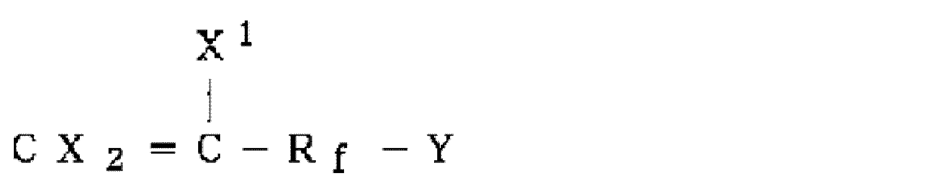
(式中、Yは-CH2OH、-COOH、カルボン酸塩、カルボキシエステル基又はエポキシ基、X及びX1は同じか又は異なりいずれも水素原子又はフッ素原子、Rfは炭素数1~40の2価の含フッ素アルキレン基又は炭素数1~40のエーテル結合を含有する2価の含フッ素アルキレン基を表す)で示される少なくとも1種の官能基を有する含フッ素エチレン性単量体も使用可能である。これらの単量体を1種又は2種以上共重合することにより、更に接着性が向上し、充放電を繰り返し行っても良好な充放電サイクル特性が得られる。
これら単量体の中でも、柔軟性と耐薬品性の観点から、ヘキサフルオロプロピレン(HFP)、2,3,3,3-テトラフルオロプロペンがより好ましい。
これら単量体の中でも、柔軟性と耐薬品性の観点から、ヘキサフルオロプロピレン(HFP)、2,3,3,3-テトラフルオロプロペンがより好ましい。
上記含フッ素重合体が、VdF/TFE/HFPの3元共重合体の場合、(VdF+TFE)単位/HFP単位がモル比で90/10~99/1であり、かつ、VdF/TFE単位がモル比で40/60~95/5であることが好ましい。
HFP単位は、10モル%を超えると電解液への膨潤性が過度に高くなるおそれがある。好ましいHFP単位の含有量は5モル%以下、さらには4モル%以下である。HFP単位の含有量の好ましい下限は1モル%である。
HFP単位は、10モル%を超えると電解液への膨潤性が過度に高くなるおそれがある。好ましいHFP単位の含有量は5モル%以下、さらには4モル%以下である。HFP単位の含有量の好ましい下限は1モル%である。
このように上記含フッ素重合体は、VdF単位及びTFE単位の他に、他の重合単位を含むものであってもよいが、VdF単位及びTFE単位のみからなることがより好ましい。
上記含フッ素重合体は、重量平均分子量(ポリスチレン換算)が20万~200万である。上記重量平均分子量が上述の範囲内であると、多孔性基材に対する複合多孔質膜の接着性を向上させることができる。
上記重量平均分子量は、30万以上が好ましく、190万以下が好ましく、170万以下がより好ましく、150万以下が更に好ましい。
上記重量平均分子量は、ゲルパーミエーションクロマトグラフィー(GPC)により溶媒としてN,N-ジメチルホルムアミドを用い50℃で測定して得られる値である。
上記重量平均分子量は、30万以上が好ましく、190万以下が好ましく、170万以下がより好ましく、150万以下が更に好ましい。
上記重量平均分子量は、ゲルパーミエーションクロマトグラフィー(GPC)により溶媒としてN,N-ジメチルホルムアミドを用い50℃で測定して得られる値である。
上記含フッ素重合体は、融点が100~240℃であることが好ましい。上記融点は、110℃以上がより好ましく、120℃以上が更に好ましい。
上記融点は、示差走査熱量測定(DSC)装置を用い、10℃/分の速度で昇温したときの融解熱曲線における極大値に対する温度として求めることができる。
上記融点は、示差走査熱量測定(DSC)装置を用い、10℃/分の速度で昇温したときの融解熱曲線における極大値に対する温度として求めることができる。
上記含フッ素重合体を製造する方法としては、例えば、重合単位であるVdF及びTFEの単量体や、重合開始剤等の添加剤を適宜混合して、懸濁重合、乳化重合、溶液重合等を行う方法等、公知の方法を採用することができる。なかでも、後処理の容易さ等の点から水系の懸濁重合、乳化重合が好ましい。
乳化重合により含フッ素重合体を製造すると、含フッ素重合体の粒子及び水を含む水性ディスパージョンが得られる。この水性ディスパージョンの分散安定性を向上させるためにさらに界面活性剤を添加してもよい。これによって、水性ディスパージョンを長期間(例えば1週間超、1ヶ月超、6ヶ月または1年超)貯蔵保存した場合や、水性ディスパージョンの輸送時に過度の振動が加わった場合においても、粒子が凝集して1μm以上の粒径の粗大な粒子が生成したり、または粒子の沈降が起こったりすることがなく、貯蔵安定性に優れ、かつ輸送過程での振動に対しても安定な水性ディスパージョンを得ることができる。また、水性ディスパージョンの表面張力を低下させることもでき、例えば表面張力値を30mN/m以下とすることができる。後述するように、水性ディスパージョンに無機粒子を添加することにより複合多孔質膜を形成するための分散液(スラリー状塗工液)を調製することができるのであるが、水性ディスパージョンの表面張力を低下させることによって、含フッ素重合体の粒子だけでなく、無機粒子についても、良好に分散した分散液を得ることができる。優れた分散性を有する分散液は、多孔性基材への浸透性が高く、得られる複合多孔質膜が均一性に優れるという効果も達成される。
水性ディスパージョンに添加する界面活性剤としては、ノニオン性界面活性剤、アニオン性界面活性剤、カチオン性界面活性剤、両性界面活性剤、高分子界面活性剤又はそれらの組み合わせを使用することができる。ノニオン性界面活性剤としては、非フッ素化ノニオン性界面活性剤であることが好ましく、例えばポリオキシエチレンアルキルエーテル、ポリオキシエチレンアルキルエステル、ポリオキシエチレンアルキルフェニルエーテル、ソルビタンアルキレート、ポリオキシエチレンドルビタンモノアルキレート、エチレンオキシド/プロピレンオキシド共重合体、ポリオキシエチレンアリールエーテル、ポリオキシエチレンアルキルアミンエーテル等を挙げることができる。アニオン性界面活性剤としては、非フッ素化アニオン性界面活性剤であることが好ましく、例えば高級アルコールの硫酸エステルのナトリウム塩、アルキルベンゼンスルホン酸塩、アルカンスルホン酸塩、アルキル硫酸塩、アルキルホスホン酸塩、アルキルリン酸塩、ポリオキシエチレンアルキルエーテル硫酸エステル塩、ポリオキシエチレンアルキルエステル硫酸エステル塩、ポリオキシエチレンアルキルフェニルエーテルの硫酸エステル塩、モノアルキルサクシネートスルホン酸塩、ジアルキルスクシネートスルホン酸塩等を挙げることができる。カチオン性界面活性剤としては、非フッ素化カチオン性界面活性剤であることが好ましく、例えばアルキルピリジニウムクロリド、アルキルアンモニウムクロリド、アルキルイミダゾリン、アルキルアンモニウムハイドライド等を挙げることができる。両性界面活性剤としては、非フッ素化両性界面活性剤であることが好ましく、例えばアルキルイミダゾリウムベタイン、アミドアルキルベタイン等を挙げることができる。高分子界面活性剤としては、ポリアクリル酸塩、ポリアクリル酸アンモニウム、ポリメタクリル酸塩、ポリメタクリル酸アンモニウム、ナフタレンスルホン酸ホルマリン縮合物等を挙げることができる。
斯かる界面活性剤の中でも、含フッ素重合体の粒子及び無機粒子を分散させる効果が高いことから、ノニオン性界面活性剤が好ましく、非フッ素化ノニオン性界面活性剤であることがより好ましい。さらに、熱分解したときに有害な有機芳香族化合物(ベンゼン、トルエン、キシレンなど)に変換されて大気汚染を引き起こす懸念や臭気面での懸念もない観点から、
式:RO(CH2CH2O)nH
(Rは炭素数8~18の飽和もしくは不飽和の炭化水素基、nは5~18の整数を示す)で表され、分子中のオキシエチレン含量が60~75質量%であるポリオキシエチレンアルキルエーテルがより好ましい。上記炭化水素基がフッ素原子を含まないことは、その用語の通常の意味から当然である。
また、斯かる界面活性剤の中でも、含フッ素重合体の粒子及び無機粒子を分散させる効果が高いことから、非フッ素化ノニオン性界面活性剤及び非フッ素化アニオン性界面活性剤からなる群より選択される少なくとも1種がより好ましく、非フッ素化ノニオン性界面活性剤がより好ましく、非フッ素化ノニオン性界面活性剤及び非フッ素化アニオン性界面活性剤の組み合わせが更に好ましい。
斯かる界面活性剤の中でも、含フッ素重合体の粒子及び無機粒子を分散させる効果が高いことから、ノニオン性界面活性剤が好ましく、非フッ素化ノニオン性界面活性剤であることがより好ましい。さらに、熱分解したときに有害な有機芳香族化合物(ベンゼン、トルエン、キシレンなど)に変換されて大気汚染を引き起こす懸念や臭気面での懸念もない観点から、
式:RO(CH2CH2O)nH
(Rは炭素数8~18の飽和もしくは不飽和の炭化水素基、nは5~18の整数を示す)で表され、分子中のオキシエチレン含量が60~75質量%であるポリオキシエチレンアルキルエーテルがより好ましい。上記炭化水素基がフッ素原子を含まないことは、その用語の通常の意味から当然である。
また、斯かる界面活性剤の中でも、含フッ素重合体の粒子及び無機粒子を分散させる効果が高いことから、非フッ素化ノニオン性界面活性剤及び非フッ素化アニオン性界面活性剤からなる群より選択される少なくとも1種がより好ましく、非フッ素化ノニオン性界面活性剤がより好ましく、非フッ素化ノニオン性界面活性剤及び非フッ素化アニオン性界面活性剤の組み合わせが更に好ましい。
無機粒子を配合する前の水性ディスパージョンは、上記界面活性剤を0.1~5質量%含むことが好ましく、0.3~4質量%含むことがより好ましく、0.5~3質量%含むことが更に好ましい。界面活性剤濃度が5質量%を超えると、セパレータの耐酸化性が低下して電気特性に悪影響を与えるおそれがある。界面活性剤濃度が0.1質量%未満では、水性ディスパージョンの貯蔵安定性が十分に向上されなかったり、長期の貯蔵保存時や輸送時に粗大粒子の凝集または沈降が生じたりするおそれがある。
無機粒子を配合する前の水性ディスパージョンは、塗工プロセスでの生産性(塗工効率)向上の観点から含フッ素重合体(固形分換算)の濃度が10質量%以上であることが好ましく、20質量%以上であることがより好ましく、また貯蔵安定性の観点から60質量%以下であることが好ましく、50質量%以下であることがより好ましい。
上記含フッ素重合体の含有量は、複合多孔質膜中50質量%以下である。
50質量%を超えると、複合多孔質膜中の気孔度が下がりすぎて、セパレータとしてのイオン透過機能が果たされなくなる。
上記含フッ素重合体の含有量は、無機粒子間の接着が不十分となり、複合多孔質膜の機械的物性が著しく低下するおそれがある点で、複合多孔質膜中1質量%以上であることが好ましい。
上記含フッ素重合体の含有量は、複合多孔質膜中45質量%以下が好ましく、40質量%以下がより好ましく、2質量%以上がより好ましく、3質量%以上が更に好ましく、4質量%以上であることが特に好ましい。
50質量%を超えると、複合多孔質膜中の気孔度が下がりすぎて、セパレータとしてのイオン透過機能が果たされなくなる。
上記含フッ素重合体の含有量は、無機粒子間の接着が不十分となり、複合多孔質膜の機械的物性が著しく低下するおそれがある点で、複合多孔質膜中1質量%以上であることが好ましい。
上記含フッ素重合体の含有量は、複合多孔質膜中45質量%以下が好ましく、40質量%以下がより好ましく、2質量%以上がより好ましく、3質量%以上が更に好ましく、4質量%以上であることが特に好ましい。
上記複合多孔質膜は、金属酸化物粒子および金属水酸化物粒子からなる群より選択される少なくとも1種の無機粒子を含む。上記無機粒子の含有量は、複合多孔質膜中50~99質量%であることが好ましい。上記無機粒子の含有量が上述の範囲内であると、リチウムイオンの透過を妨げない気孔径ならびに気孔度を有する複合多孔質膜が積層されたセパレータを得ることができる。更に、耐熱性が高く、熱による収縮が少ないセパレータを実現できる。
上記無機粒子の含有量は、複合多孔質膜中55質量%以上がより好ましく、60質量%以上が更に好ましく、98質量%以下がより好ましく、97質量%以下が更に好ましく、96質量%以下が特に好ましい。
上記無機粒子は、平均粒子径が20μm以下であることが好ましく、10μm以下がより好ましく、5μm以下が更に好ましい。上記平均粒子径の下限は、0.001μmが好ましい。
上記平均粒子径は、透過型電子顕微鏡、レーザー式粒度分布測定装置などにより測定して得られる値である。
上記無機粒子の含有量は、複合多孔質膜中55質量%以上がより好ましく、60質量%以上が更に好ましく、98質量%以下がより好ましく、97質量%以下が更に好ましく、96質量%以下が特に好ましい。
上記無機粒子は、平均粒子径が20μm以下であることが好ましく、10μm以下がより好ましく、5μm以下が更に好ましい。上記平均粒子径の下限は、0.001μmが好ましい。
上記平均粒子径は、透過型電子顕微鏡、レーザー式粒度分布測定装置などにより測定して得られる値である。
上記金属酸化物粒子としては、セパレータのイオン伝導性、シャットダウン効果を向上させる観点からアルカリ金属またはアルカリ土類金属以外の金属酸化物が好ましく、酸化アルミニウム、酸化ケイ素、酸化チタン、酸化バナジウムおよび酸化銅からなる群より選択される少なくとも1種がより好ましい。
上記金属酸化物粒子は、平均粒子径が20μm以下であることが好ましく、10μm以下がより好ましく、5μm以下が更に好ましい。上記平均粒子径の下限は、0.001μmが好ましい。
上記平均粒子径は、透過型電子顕微鏡により測定して得られる値である。
上記平均粒子径は、透過型電子顕微鏡により測定して得られる値である。
特に好ましい金属酸化物粒子は、イオン伝導性に優れる点から、平均粒子径が5μm以下の酸化アルミニウム粒子又は酸化ケイ素粒子である。
上記金属酸化物粒子の含有量は、複合多孔質膜中50~99質量%であることが好ましい。上記金属酸化物粒子の含有量が上述の範囲内であると、リチウムイオンの透過を妨げない気孔径ならびに気孔度を有する複合多孔質膜が積層されたセパレータを得ることができる。更に、耐熱性が高く、熱による収縮が少ないセパレータを実現できる。
上記金属酸化物粒子の含有量は、複合多孔質膜中55質量%以上がより好ましく、60質量%以上が更に好ましく、98質量%以下がより好ましく、97質量%以下が更に好ましく、96質量%以下が特に好ましい。
上記金属酸化物粒子の含有量は、複合多孔質膜中55質量%以上がより好ましく、60質量%以上が更に好ましく、98質量%以下がより好ましく、97質量%以下が更に好ましく、96質量%以下が特に好ましい。
上記金属水酸化物粒子としては、セパレータのイオン伝導性、シャットダウン効果を向上させる観点から、アルカリ金属またはアルカリ土類金属の水酸化物が好ましく、水酸化マグネシウム、水酸化カルシウム、水酸化アルミニウム、水酸化クロム、水酸化ジルコニウムおよび水酸化ニッケルからなる群より選択される少なくとも1種がより好ましい。
上記金属水酸化物粒子は、平均粒子径が20μm以下であることが好ましく、10μm以下がより好ましく、5μm以下が更に好ましい。上記平均粒子径の下限は、0.001μmが好ましい。
上記平均粒子径は、透過型電子顕微鏡により測定して得られる値である。
上記平均粒子径は、透過型電子顕微鏡により測定して得られる値である。
上記金属水酸化物粒子の含有量は、複合多孔質膜中50~99質量%であることが好ましい。上記金属水酸化物粒子の含有量が上述の範囲内であると、リチウムイオンの透過を妨げない気孔径ならびに気孔度を有する複合多孔質膜が積層されたセパレータを得ることができる。更に、耐熱性が高く、熱による収縮が少ないセパレータを実現できる。
上記金属水酸化物粒子の含有量は、複合多孔質膜中55質量%以上がより好ましく、60質量%以上が更に好ましく、98質量%以下がより好ましく、97質量%以下が更に好ましい。
上記金属水酸化物粒子の含有量は、複合多孔質膜中55質量%以上がより好ましく、60質量%以上が更に好ましく、98質量%以下がより好ましく、97質量%以下が更に好ましい。
上記複合多孔質膜は、更に、有機系粒子を含むことが好ましい。上記有機系粒子としては、非導電性の架橋ポリマーが好ましく、架橋ポリスチレン、架橋ポリメタクリレート、架橋アクリレートがより好ましい。
上記有機系粒子は、平均粒子径が20μm以下であることが好ましく、10μm以下がより好ましく、5μm以下が更に好ましい。上記平均粒子径の下限は、0.001μmが好ましい。
上記平均粒子径は、透過型電子顕微鏡により測定して得られる値である。
上記平均粒子径は、透過型電子顕微鏡により測定して得られる値である。
上記有機系粒子の含有量は、複合多孔質膜中0~49質量%であることが好ましい。上記有機系粒子の含有量が上述の範囲内であると、リチウムイオンの透過を妨げない気孔径ならびに気孔度を有する複合多孔質膜が積層されたセパレータを得ることができる。
上記有機系粒子の含有量は、複合多孔質膜中2質量%以上がより好ましく、5質量%以上が更に好ましく、37質量%以下がより好ましく、35質量%以下が更に好ましい。
上記有機系粒子の含有量は、複合多孔質膜中2質量%以上がより好ましく、5質量%以上が更に好ましく、37質量%以下がより好ましく、35質量%以下が更に好ましい。
上記複合多孔質膜は、上述した含フッ素重合体、無機粒子以外に、他の成分を更に含んでいてもよい。他の成分としては、他の樹脂やゴム等が挙げられる。
併用する好ましい樹脂としては、例えば、ポリアクリレート、ポリメタクリレート、ポリアクリルニトリル、ポリアミドイミド、ポリフッ化ビニリデン(PVdF)、VdF/HEP共重合体樹脂の1種または2種以上などが挙げられる。
併用する好ましいゴムとしては、例えば、VdF/HFP共重合体ゴム、VdF/TFE/HFP共重合体ゴム、アクリルゴムなどの1種または2種以上が挙げられる。これらのゴムは、架橋されていてもされていなくてもよい。
併用する好ましい樹脂としては、例えば、ポリアクリレート、ポリメタクリレート、ポリアクリルニトリル、ポリアミドイミド、ポリフッ化ビニリデン(PVdF)、VdF/HEP共重合体樹脂の1種または2種以上などが挙げられる。
併用する好ましいゴムとしては、例えば、VdF/HFP共重合体ゴム、VdF/TFE/HFP共重合体ゴム、アクリルゴムなどの1種または2種以上が挙げられる。これらのゴムは、架橋されていてもされていなくてもよい。
併用する樹脂またはゴムとして、特に好ましいものは、イオン伝導性の向上の点からはアクリルゴムが、またイオン伝導性の向上と耐酸化性の向上の点からは、VdF/HFP共重合体ゴム、VdF/TFE/HFP共重合体ゴム、VdF/HFP樹脂が挙げられる。
VdF/HFP共重合体ゴムは、VdF単位/HFP単位がモル比で80/20~65/35であることが好ましい。
VdF/TFE/HFP共重合体ゴムは、VdF単位/HFP単位/TFE単位がモル比で80/5/15~60/30/10であることが好ましい。
VdF/HFP樹脂は、VdF単位/HFP単位がモル比で98/2~85/15であることが好ましい。
VdF/HFP樹脂は、融点が100~200℃であることが好ましい。
VdF/TFE/HFP共重合体ゴムは、VdF単位/HFP単位/TFE単位がモル比で80/5/15~60/30/10であることが好ましい。
VdF/HFP樹脂は、VdF単位/HFP単位がモル比で98/2~85/15であることが好ましい。
VdF/HFP樹脂は、融点が100~200℃であることが好ましい。
他の樹脂またはゴムの配合量は、上記含フッ素重合体100質量部に対して好ましくは400質量部以下、より好ましくは200質量部以下、更に好ましくは150質量部以下である。下限は目的とする効果によって異なるが、10質量部程度である。
上記複合多孔質膜は、多孔性基材の上に設けられていることが好ましく、多孔質基材上に直接設けられていることがより好ましい。
また、上記複合多孔質膜は、上記多孔性基材の片側のみに設けられてもよく、両側に設けられてもよい。また、複合多孔質膜は、上記複合多孔質膜が設けられる多孔性基材の全部を覆うように設けられてもよく、一部のみを覆うように設けられてもよい。
また、上記複合多孔質膜は、上記多孔性基材の片側のみに設けられてもよく、両側に設けられてもよい。また、複合多孔質膜は、上記複合多孔質膜が設けられる多孔性基材の全部を覆うように設けられてもよく、一部のみを覆うように設けられてもよい。
上記複合多孔質膜の重量は、該複合多孔質膜を多孔性基材の片側のみに形成する場合には、0.5~50.0g/m2の範囲が好ましい。0.5g/m2より少ないと電極との接着性が充分でなくなることがある。また、50.0g/m2より多いと、イオン伝導を素子し電池の負荷特性が低下する傾向にあるので好ましくない。多孔性基材の表裏両面に上記複合多孔質膜を形成する場合の上記含フッ素重合体の重量は、0.1~6.0g/m2が好ましい。
上記の多孔性基材とは、内部に空孔ないし空隙を有する基材を意味する。このような基材としては、微多孔膜や、不織布、上条シート等の繊維状物からなる多孔性シート、あるいは、これら微多孔膜や多孔性シートに他の多孔性層を1層以上積層させた複合多孔質膜等を挙げることができる。なお、微多孔膜とは、内部に多数の微細孔を有し、これら微細孔が連結された構造となっており、一方の面から他方の面へと気体あるいは液体が通過可能となった膜を意味する。
多孔性基材を構成する材料は、電気絶縁性を有する有機材料あるいは無機材料のいずれでも使用できる。特に、基材にシャットダウン機能を付与する観点からは、基材の構成材料として熱可塑性樹脂を使用することが好ましい。ここで、シャットダウン機能とは、電池温度が高まった場合に、熱可塑性樹脂が溶解して多孔性基材の孔を閉塞することによりイオンの移動を遮断し、電池の熱暴走を防止する機能をいう。熱可塑性樹脂としては、融点200℃未満の熱可塑性樹脂が適当であり、特にポリオレフィンが好ましい。
ポリオレフィンを用いた多孔性基材としてはポリオレフィン微多孔膜が好適である。ポリオレフィン微多孔膜としては、充分な力学物性とイオン透過性を有した、従来の非水系二次電池用セパレータに適用されているポリオレフィン微多孔膜を用いることができる。そして、ポリオレフィン微多孔膜は、上述したシャットダウン機能を有するという観点から、ポリエチレンを含むことが好ましい。
ポリオレフィンの重量平均分子量は10万~500万のものが好適である。重量平均分子量が10万より小さいと、十分な力学物性を確保するのが困難となる場合がある。また、500万より大きくなると、シャットダウン特性が悪くなる場合や、成形が困難になる場合がある。
このようなポリオレフィン微多孔膜は、例えば以下の方法で製造可能である。すなわち、(i)溶融したポリオレフィン樹脂をT-ダイから押し出してシート化する工程、(ii)上記シートに結晶化処理を施す工程、(iii)シートを延伸する工程、及び(iv)シートを熱処理する工程を順次実施して、微多孔膜を形成する方法が挙げられる。また、(i)流動パラフィン等の可塑剤と一緒にポリオレフィン樹脂を溶融し、これをT-ダイから押し出し、これを冷却してシート化する工程、(ii)シートを延伸する工程、(iii)シートから可塑剤を抽出する工程、及び(iv)シートを熱処理する工程を順次実施して微多孔膜を形成する方法等も挙げられる。
繊維状物からなる多孔性シートとしては、ポリエチレンテレフタレート等のポリエステル、ポリエチレンやポリプロピレン等のポリオレフィン、芳香族ポリアミドやポリイミド、ポリエーテルスルホン、ポリスルホン、ポリエーテルケトン、ポリエーテルイミド等の耐熱性高分子等からなる繊維状物、あるいは、これらの繊維状物の混合物からなる多孔性シートを用いることができる。
上記多孔性基材は、更に機能層を積層した複合多孔性基材であってもよい。
上記複合多孔性基材は、機能層によってさらなる機能付加が可能となる点で好ましい。機能層としては、例えば耐熱性を付与するという観点では、耐熱性樹脂からなる多孔質層や、耐熱性樹脂及び無機フィラーからなる多孔質層を用いることができる。耐熱性樹脂としては、芳香族ポリアミド、ポリイミド、ポリエーテルスルホン、ポリスルホン、ポリエーテルケトン、及びポリエーテルイミドから選ばれる1種又は2種以上の耐熱性高分子が挙げられる。無機フィラーとしては、アルミナ等の金属酸化物や、水酸化マグネシウム等の金属水酸化物等を好適に使用できる。なお、複合化の手法としては、多孔性シートに機能層をコーティングする方法、接着剤で接合する方法、熱圧着する方法等が挙げられる。
上記複合多孔性基材は、機能層によってさらなる機能付加が可能となる点で好ましい。機能層としては、例えば耐熱性を付与するという観点では、耐熱性樹脂からなる多孔質層や、耐熱性樹脂及び無機フィラーからなる多孔質層を用いることができる。耐熱性樹脂としては、芳香族ポリアミド、ポリイミド、ポリエーテルスルホン、ポリスルホン、ポリエーテルケトン、及びポリエーテルイミドから選ばれる1種又は2種以上の耐熱性高分子が挙げられる。無機フィラーとしては、アルミナ等の金属酸化物や、水酸化マグネシウム等の金属水酸化物等を好適に使用できる。なお、複合化の手法としては、多孔性シートに機能層をコーティングする方法、接着剤で接合する方法、熱圧着する方法等が挙げられる。
本発明における多孔性基材としては、上述したなかでも、ポリエチレン、ポリプロピレン、ポリイミド、ポリアミド、ポリエチレンテレフタレート、ポリエステルおよびポリアセタールからなる群より選択される少なくとも1種の樹脂からなることが好ましい。
本発明において、多孔性基材の膜厚は、良好な力学物性と内部抵抗を得る観点から、5~50μmの範囲が好ましい。
本発明のセパレータは、上記多孔性基材の上に上記複合多孔質膜を積層することにより製造することができる。積層方法としては、特に限定されず、従来公知の方法を採用してよい。具体的には、上記含フッ素重合体、無機粒子及び必要に応じてその他の成分を溶剤あるいは水に溶解又は分散させ得られた溶液又は分散液を多孔性基材にロールコーティングする方法、上記溶液又は分散液に多孔性基材をディッピングする方法、上記溶液又は分散液を多孔性基材に塗工し更に適切な凝固液に浸漬し作製する方法が好ましい。また、予め上記複合多孔質膜からなるフィルムを作製し、当該フィルムと多孔性基材とをラミネート等の方法により、積層してもよい。上記複合多孔質膜からなるフィルムを作製する方法としては、上記含フッ素重合体、上記無機粒子及び必要に応じてその他の成分を溶剤に溶解又は分散した溶液又は分散液をポリエステルフィルムやアルミフィルム等の平滑な表面を有するフィルム上にキャストしたのち剥離するという手法が例示できる。
上記溶剤としては、N-メチル-2-ピロリドン等のアミド系溶剤;アセトン等のケトン系溶剤;テトラヒドロフラン等の環状エーテル系溶剤等が使用できる。また、上記含フッ素重合体及び必要に応じて配合するその他の成分を水に分散して用いてもよい。
上記含フッ素重合体及び無機粒子を含む溶液又は分散液は、水系の場合、乳化重合等により得られた含フッ素重合体の水性分散液に、無機粒子と、粘度調製用の増粘剤(安定化剤)とを配合して調製したものであってもよい。
上記増粘剤(安定化剤)としては、カルボキシアルキルセルロース、アルキルセルロース、ヒドロキシアルキルセルロース等が挙げられる。
得られた上記溶液又は分散液を多孔性基材上に塗布して、乾燥し、複合多孔質膜を形成するとよい。
上記増粘剤(安定化剤)としては、カルボキシアルキルセルロース、アルキルセルロース、ヒドロキシアルキルセルロース等が挙げられる。
得られた上記溶液又は分散液を多孔性基材上に塗布して、乾燥し、複合多孔質膜を形成するとよい。
上記含フッ素重合体及び無機粒子を含む溶液又は分散液は、溶剤系の場合、乳化重合等により得られた含フッ素重合体の水性分散液を凝析し、乾燥して、含フッ素重合体の粉末としたものと、無機粒子と、溶剤とを配合して調製したものであってもよい。
得られた上記溶液又は分散液を多孔性基材上に塗布して、乾燥し、複合多孔質膜を形成するとよい。
得られた上記溶液又は分散液を多孔性基材上に塗布して、乾燥し、複合多孔質膜を形成するとよい。
上記多孔質基材上に上記複合多孔質膜を形成する方法としては、上記含フッ素重合体、上記無機粒子及び水を含む分散液(スラリー状塗工液)を公知の方法により多孔質基材上に塗工し、乾燥させる方法が好適である。上記スラリー状塗工液には、上述した有機系粒子、増粘剤等が含まれていてもよい。
上記スラリー状塗工液は、上記含フッ素重合体を0.5~25質量%含むことが好ましく、1質量%以上含むことがより好ましく、20質量%以下含むことがより好ましい。上記含フッ素重合体の濃度は、含フッ素重合体と無機粒子と水の配合比に応じて調整することができる。
上記スラリー状塗工液は、上記無機粒子を1~60質量%含むことが好ましく、2質量%以上含むことがより好ましく、55質量%以下含むことがより好ましい。上記無機粒子の濃度は、含フッ素重合体と無機粒子と水の配合比に応じて調整することができる。
上記スラリー状塗工液が有機系粒子を含む場合、1~60質量%含むことが好ましく、2質量%以上含むことがより好ましく、55質量%以下含むことがより好ましい。上記有機系粒子の濃度は、含フッ素重合体と無機粒子と水の配合比に応じて調整することができる。
上記スラリー状塗工液が増粘剤を含む場合、0.1~20質量%含むことが好ましい。上記増粘剤の濃度は、スラリー状塗工液への増粘剤の添加量に応じて調整することができる。
上記スラリー状塗工液は、水の存在下に、VdF及びTFEを乳化重合して、水及び含フッ素重合体を含む分散液を得る工程、及び、得られた分散液に無機粒子を添加する工程を含む製造方法により、好適に製造することができる。VdF及びTFEに加えて、VdF及びTFEと共重合し得る単量体を重合してもよい。VdF及びTFEと共重合し得る単量体については、上述したとおりである。また、必要に応じて、上述した有機系粒子、増粘剤等を添加してもよい。また、乳化重合の後、得られた分散液を濃縮又は希釈して、含フッ素重合体の濃度を調整する工程を含むことも好ましい。
含フッ素重合体及び水を含む分散液は、水及び界面活性剤の存在下に、VdF及びTFEを乳化重合する工程を含む製造方法により特に好適に製造することができる。上記製造方法において、VdF及びTFEに加えて、VdF及びTFEと共重合し得る単量体を重合してもよい。VdF及びTFEと共重合し得る単量体については、上述したとおりである。
上記界面活性剤としては、従来公知の界面活性剤を使用することができるが、フッ素化界面活性剤は、難分解性のため環境中への蓄積が懸念され、環境に与える影響が大きい。また、非フッ素化界面活性剤は、含フッ素重合体を製造する工程で、連鎖移動剤として機能する為、重合体の分子量を上げることが困難である。本発明者が鋭意検討した結果、反応性フッ素化界面活性剤を使用することによって、環境へ影響を与えることなく、高分子量の含フッ素重合体を製造することが見出された。反応性界面活性剤であっても、非フッ素化反応性界面活性剤を使用すると、高分子量の含フッ素重合体を製造することができない。また、環境に与える影響が小さく、しかも、反応性フッ素化界面活性剤はVdF及びTFEなどと共重合され、消費されるため、実質的にフッ素化界面活性剤を含んでいない含フッ素重合体および水を含む分散液を製造することができる、という利点があることから、上記界面活性剤として、反応性フッ素化界面活性剤のみを使用することが好ましい。
上記反応性フッ素化界面活性剤は、水に対して10~1000ppmの量とすることが好ましく、50ppm以上とすることがより好ましく、500ppm以下とすることがより好ましい。
上記反応性フッ素化界面活性剤としては、下記式(a)~(e)で表される化合物からなる群より選択される少なくとも1種であることが好ましく、式(e)で表される化合物であることがより好ましい。
CF2=CF-(CF2)n1-Y3 (a)
(式中、n1は、1~10の整数を表し、Y3は、-SO3M1又は-COOM1を表し、M1は、H、NH4又はアルカリ金属を表す。)
CF2=CF-(CF2C(CF3)F)n2-Y3 (b)
(式中、n2は、1~5の整数を表し、Y3は、前記定義と同じ。)
CF2=CF-O-(CFX2)n3-Y3 (c)
(式中、X2は、F又はCF3を表し、n3は、1~10の整数を表し、Y3は、前記定義と同じ。)
CF2=CF-O-(CF2CFX2O)n4-CF2CF2-Y3 (d)
(式中、n4は、1~10の整数を表し、Y3及びX2は、前記定義と同じ。)
CX3 2=CFCF2-O-(CF(CF3)CF2O)n5-CF(CF3)-Y3 (e)
(式中、各X3は、同一であり、F又はHを表す。n5は、0又は1~10の整数を表し、Y3は、前記定義と同じ。)
上記アルカリ金属としては、Na、K等が挙げられる。
CF2=CF-(CF2)n1-Y3 (a)
(式中、n1は、1~10の整数を表し、Y3は、-SO3M1又は-COOM1を表し、M1は、H、NH4又はアルカリ金属を表す。)
CF2=CF-(CF2C(CF3)F)n2-Y3 (b)
(式中、n2は、1~5の整数を表し、Y3は、前記定義と同じ。)
CF2=CF-O-(CFX2)n3-Y3 (c)
(式中、X2は、F又はCF3を表し、n3は、1~10の整数を表し、Y3は、前記定義と同じ。)
CF2=CF-O-(CF2CFX2O)n4-CF2CF2-Y3 (d)
(式中、n4は、1~10の整数を表し、Y3及びX2は、前記定義と同じ。)
CX3 2=CFCF2-O-(CF(CF3)CF2O)n5-CF(CF3)-Y3 (e)
(式中、各X3は、同一であり、F又はHを表す。n5は、0又は1~10の整数を表し、Y3は、前記定義と同じ。)
上記アルカリ金属としては、Na、K等が挙げられる。
上記式(a)において、上記n1は、5以下の整数であることが好ましく、2以下の整数であることがより好ましい。上記Y3は、適度な水溶性及び界面活性を得られる点で、-COOM1であることが好ましく、M1は、不純物として残留しにくく、得られる成形体の耐熱性が向上する点で、H又はNH4であることが好ましい。
上記式(a)で表される化合物としては、例えば、CF2=CFCF2COOM1(式中、M1は上記定義と同じ。)が挙げられる。
上記式(b)において、上記n2は、乳化能の点で、3以下の整数であることが好ましく、Y3は、適度な水溶性及び界面活性が得られる点で、-COOM1であることが好ましく、M1は、不純物として残留しにくく、得られる成形体の耐熱性が向上する点で、H又はNH4であることが好ましい。
上記式(c)において、上記n3は、水溶性の点で5以下の整数であることが好ましく、上記Y3は、適度な水溶性及び界面活性が得られる点で、-COOM1であることが好ましく、上記M1は、分散安定性がよくなる点で、H又はNH4であることが好ましい。
上記式(d)において、上記X2は、界面活性能の点で、-CF3であることが好ましく、上記n4は、水溶性の点で5以下の整数であることが好ましく、上記Y3は、適度な水溶性と界面活性が得られる点で-COOM1であることが好ましく、上記M1は、H又はNH4であることが好ましい。
上記式(d)で表される化合物としては、例えば、CF2=CFOCF2CF(CF3)OCF2CF2COOM1(式中、M1は、H、NH4又はアルカリ金属を表す。)が挙げられる。
上記式(e)において、上記n5は乳化能の点で0又は1~5の整数であることが好ましく、0、1又は2であることがより好ましく、0又は1であることが更に好ましい。上記Y3は、適度な水溶性と界面活性が得られる点で-COOM1であることが好ましく、上記M1は、不純物として残留しにくく、得られた成形体の耐熱性が向上する点で、H又はNH4であることが好ましい。
上記式(e)で表される化合物としては、例えば、CH2=CFCF2OCF(CF3)CF2OCF(CF3)COOM1(式中、M1は上記定義と同じ。)が挙げられる。
上記乳化重合は、更に、パラフィンの存在下に実施することが好ましい。パラフィンが存在することにより、生成した含フッ素重合体が乳化重合に使用する重合槽や攪拌翼に付着することを防ぐことができ、高分子量の含フッ素重合体を得ることができる。
上記製造方法は、更に、乳化重合により得られた分散液に、非フッ素化ノニオン性界面活性剤、非フッ素化アニオン性界面活性剤及び非フッ素化カチオン性界面活性剤からなる群より選択される少なくとも1種の非フッ素化界面活性剤を添加する工程を含むことが、分散安定性の観点から好ましい。この工程は、無機粒子を添加する工程の前に実施してもよいし、後に実施してもよいが、無機粒子を添加する工程の前に実施することが好ましい。上記非フッ素化界面活性剤は、分散液に対して0.1~5質量%となるように添加することが好ましい。より好ましくは、0.2~4.5質量%であり、更に好ましくは0.3~4質量%である。上記非フッ素化界面活性剤として好ましいものは、上述したとおりである。
上記製造方法により、VdF単位及びTFE単位を含む含フッ素重合体の粒子を含有する分散液を得ることができる。更に、フッ素化界面活性剤を実質的に含まない分散液を製造することも可能である。上記製造方法により得られる分散液は、通常、上記含フッ素重合体を10~60質量%含む。
反応性フッ素化界面活性剤の存在下に乳化重合することにより得られ、かつ、VdF単位及びTFE単位を含む含フッ素重合体の粒子及び水を含み、上記含フッ素重合体の重量平均分子量が20万以上であり、フッ素化界面活性剤を実質的に含まない分散液は、新規な分散液である。上記分散液は、二次電池用セパレータを製造するための分散液として好適に使用できる。
上記分散液は、高分子量の含フッ素重合体の粒子を含有することが特徴の一つである。含フッ素重合体の重量平均分子量は、20万以上であることが好ましく、30万以上であることがより好ましく、200万以下であることが好ましく、190万以下であることがより好ましい。
上記分散液に含まれる含フッ素重合体において、VdF単位の量は特に限定されないが、VdF単位を全重合単位中40モル%以上含むことが好ましく、全重合単位中95モル%以下含むことが好ましく、93モル%以下含むことがより好ましい。
上記分散液に含まれる含フッ素重合体において、TFE単位の量は特に制限されないが、TFE単位を全重合単位中5~60モル%含むことが好ましい。TFE単位の含有量は、全重合単位中7モル%以上がより好ましく、50モル%以下がより好ましい。
上記分散液は、上記含フッ素重合体を10~60質量%含むことが好ましく、15質量%以上含むことがより好ましく、50質量%以下含むことがより好ましい。上記含フッ素重合体の濃度は、乾燥重量法(乳化重合により得られた分散液を加熱して溶媒乾固させた後、固形分重量を秤量する方法)により測定することができる。
上記含フッ素重合体及び水を含む分散液は、フッ素化界面活性剤の濃度が含フッ素重合体及び水を含む分散液に対して4000ppm以下であることが好ましく、1000ppm以下であることがより好ましく、100ppm以下であることが更に好ましく、10ppm以下であることが更により好ましく、1000ppb以下であることが殊更に好ましく、500ppb以下であることが特に好ましく、フッ素化界面活性剤を実質的に含まないことが最も好ましい。
上記フッ素化界面活性剤の濃度は、分散液を凝析した後、遠心分離し、液相を以下の条件にて超高速液体クロマトグラフィー(UPLC)により求めることができる。なお、フッ素化界面活性剤の含有量算出にあたり、含有量既知のフッ素化界面活性剤水溶液について下記条件にてUPLC測定して得られた検量線を用いる。検出限界は分散液に対して10ppbである。
上記フッ素化界面活性剤の濃度は、分散液を凝析した後、遠心分離し、液相を以下の条件にて超高速液体クロマトグラフィー(UPLC)により求めることができる。なお、フッ素化界面活性剤の含有量算出にあたり、含有量既知のフッ素化界面活性剤水溶液について下記条件にてUPLC測定して得られた検量線を用いる。検出限界は分散液に対して10ppbである。
(測定条件)
装置:AcquityTMUltraPerformanceLC(Waters社製)
カラム;BEHC181.7μm(2.1×50mm)
移動相;アセトニトリル/20mM酢酸アンモニウム水溶液=1/1(vol/vol%)
サンプル量;5μL
流速;0.4ml/分
測定質量数;421>163
カラム温度;40℃
装置:AcquityTMUltraPerformanceLC(Waters社製)
カラム;BEHC181.7μm(2.1×50mm)
移動相;アセトニトリル/20mM酢酸アンモニウム水溶液=1/1(vol/vol%)
サンプル量;5μL
流速;0.4ml/分
測定質量数;421>163
カラム温度;40℃
上記フッ素化界面活性剤としては、フッ素原子を有する界面活性剤であれば特に限定されず、ノニオン界面活性剤、アニオン界面活性剤、カチオン界面活性剤、又は、両性界面活性剤の何れであってもよく、また、反応性フッ素化界面活性剤も含む。すなわち、上記分散液は、乳化重合において使用した反応性フッ素化界面活性剤をも実質的に含まない。
上記フッ素化界面活性剤は、数平均分子量が1000以下であることが多く、500以下であるものも多い。また、炭素数が5~12であるものが通常である。本明細書において、数平均分子量は、GPC(ゲルパーミエーションクロマトグラフ)測定によるポリスチレン換算の測定値である。高分子量のフッ素化界面活性剤は、環境に与える影響が小さいことから、上記分散液は、フッ素化界面活性剤のうち、高分子量のものは含むことができる。しかしながら、分子量の関わらず、フッ素化界面活性剤を含まないことが好ましい。上記フッ素化アニオン界面活性剤としては、例えば、パーフルオロカルボン酸等が挙げられる。
上記含フッ素重合体粒子は、スラリー製造における作業性を良好とする観点、複合多孔質膜中においてフッ素重合体が均一に分散して耐熱性能を十分に発現させる観点ならびに複合多孔質膜の厚みを均一かつ数マイクロメートルレベルに薄膜化できる観点から平均一次粒子径が50nm以上であることが好ましく、75nm以上であることがより好ましく、500nm以下であることが好ましく、300nm以下であることがより好ましい。上記平均一次粒子径は、動的光散乱光度計、レーザー回折散乱式粒度分布測定装置などにより測定することができる。
上記分散液は、更に、非フッ素化ノニオン性界面活性剤、非フッ素化アニオン性界面活性剤及び非フッ素化カチオン性界面活性剤からなる群より選択される少なくとも1種の非フッ素化界面活性剤を含むことが分散安定性の観点から好ましい。上記分散液は、上記非フッ素化界面活性剤を0.1~5質量%含むことが好ましく、0.2~4.5質量%含むことがより好ましく、0.3~4質量%含むことが更に好ましい。上記非フッ素化界面活性剤として好ましいものは、上述したとおりである。
上記分散液は、表面張力が50mN/m以下であることが好ましく、45mN/m以下であることがより好ましく、40mN/m以下であることが更に好ましく、下限は特に限定されないが、15mN/mであってよい。上記表面張力は、白金プレートを用いたWilhelmy法などにより測定することができる。
上記製造方法により得られた分散液又は上記の新規な分散液を、必要に応じて所望の濃度に調整した後、金属酸化物粒子及び金属水酸化物粒子からなる群より選択される少なくとも1種の無機粒子を添加して、複合多孔質膜を形成するための分散液(スラリー状塗工液)を製造することができる。必要に応じて、上述した有機系粒子、増粘剤等を添加してもよい。
本発明の二次電池用セパレータは、正極、負極及び非水電解液とともに、二次電池を構成することができる。
本発明の二次電池用セパレータを備える二次電池は、高温環境下でも安定して作動させることができ、耐久性も高い。また、ハイレート特性に優れ、高電圧で充放電を繰り返しても抵抗が増加しにくい。
本発明は、上記セパレータ、正極、負極及び非水電解液を備える二次電池でもある。
本発明の二次電池は、高温環境下でも安定して作動させることができ、耐久性も高い。また、ハイレート特性に優れ、高電圧で充放電を繰り返しても抵抗が増加しにくい。
正極、負極及び非水電解液としては、二次電池に使用可能な公知のものを使用してよい。
本発明の二次電池用セパレータを備える二次電池は、高温環境下でも安定して作動させることができ、耐久性も高い。また、ハイレート特性に優れ、高電圧で充放電を繰り返しても抵抗が増加しにくい。
本発明は、上記セパレータ、正極、負極及び非水電解液を備える二次電池でもある。
本発明の二次電池は、高温環境下でも安定して作動させることができ、耐久性も高い。また、ハイレート特性に優れ、高電圧で充放電を繰り返しても抵抗が増加しにくい。
正極、負極及び非水電解液としては、二次電池に使用可能な公知のものを使用してよい。
二次電池としては、なかでもリチウム二次電池が特に好ましい。以下に、本発明の二次電池がリチウム二次電池である場合の代表的な構成について説明するが、本発明の二次電池はこれらの構成に限定されるものではない。
正極は、正極の材料である正極活物質を含む正極合剤と、集電体とから構成される。
上記正極活物質としては、電気化学的にリチウムイオンを吸蔵・放出可能なものであれば特に制限はない。リチウムと少なくとも1種の遷移金属を含有する物質が好ましく、例えば、リチウム・コバルト複合酸化物、リチウム・ニッケル複合酸化物、リチウム・マンガン複合酸化物等のリチウム遷移金属複合酸化物、リチウム含有遷移金属リン酸化合物等が挙げられる。
上記正極合剤は、更に、結着剤、増粘剤、導電材を含むことが好ましい。
上記結着剤としては、電極製造時に使用する溶媒や電解液に対して安全な材料であれば、任意のものを使用することができ、例えば、ポリフッ化ビニリデン、ポリテトラフルオロエチレン、フッ化ビニリデン-テトラフルオロエチレン共重合体、フッ化ビニリデン-ヘキサフルオロプロピレン共重合体、フッ化ビニリデン-テトラフルオロエチレン-ヘキサフルオロプロピレン共重合体、ポリエチレン、ポリプロピレン、スチレン・ブタジエンゴム、イソプレンゴム、ブタジエンゴム、エチレン-アクリル酸共重合体、エチレン-メタクリル酸共重合体等が挙げられる。
上記結着剤としては、電極製造時に使用する溶媒や電解液に対して安全な材料であれば、任意のものを使用することができ、例えば、ポリフッ化ビニリデン、ポリテトラフルオロエチレン、フッ化ビニリデン-テトラフルオロエチレン共重合体、フッ化ビニリデン-ヘキサフルオロプロピレン共重合体、フッ化ビニリデン-テトラフルオロエチレン-ヘキサフルオロプロピレン共重合体、ポリエチレン、ポリプロピレン、スチレン・ブタジエンゴム、イソプレンゴム、ブタジエンゴム、エチレン-アクリル酸共重合体、エチレン-メタクリル酸共重合体等が挙げられる。
上記増粘剤としては、カルボキシメチルセルロース、メチルセルロース、ヒドロキシメチルセルロース、エチルセルロース、ポリビニルアルコール、酸化スターチ、リン酸化スターチ、カゼイン等が挙げられる。
上記正極の導電材としては、グラファイト、カーボンブラック等の炭素材料等が挙げられる。
正極用集電体の材質としては、アルミニウム、チタンもしくはタンタル等の金属、又は、その合金が挙げられる。なかでも、アルミニウム又はその合金が好ましい。
正極の製造は、常法によればよい。例えば、上記正極活物質に、上述した結着剤、増粘剤、導電材、溶媒等を加えてスラリー状の正極合剤とし、これを集電体に塗布し、乾燥した後にプレスして高密度化する方法が挙げられる。
負極は、負極材料を含む負極合剤と、集電体とから構成される。
上記負極材料としては、様々な熱分解条件での有機物の熱分解物や人造黒鉛、天然黒鉛等のリチウムを吸蔵・放出可能な炭素質材料;酸化錫、酸化ケイ素等のリチウムを吸蔵・放出可能な金属酸化物材料;リチウム金属;種々のリチウム合金等を挙げることができる。これらの負極材料は、2種以上を混合して用いてもよい。
リチウムを吸蔵・放出可能な炭素質材料としては、種々の原料から得た易黒鉛性ピッチの高温処理によって製造された人造黒鉛もしくは精製天然黒鉛、又は、これらの黒鉛にピッチその他の有機物で表面処理を施した後炭化して得られるものが好ましい。
上記負極合剤は、更に、結着剤、増粘剤、導電材を含むことが好ましい。
上記結着剤としては、上述した、正極に用いることができる結着剤と同様のものが挙げられる。
上記増粘剤としては、上述した、正極に用いることができる増粘剤と同様のものが挙げられる。
上記結着剤としては、上述した、正極に用いることができる結着剤と同様のものが挙げられる。
上記増粘剤としては、上述した、正極に用いることができる増粘剤と同様のものが挙げられる。
上記負極の導電材としては、銅やニッケル等の金属材料;グラファイト、カーボンブラック等の炭素材料等が挙げられる。
負極用集電体の材質としては、銅、ニッケル又はステンレス等が挙げられる。なかでも、薄膜に加工しやすいという点、及び、コストの点から銅が好ましい。
負極の製造は、常法によればよい。例えば、上記負極材料に、上述した結着剤、増粘剤、導電材、溶媒等を加えてスラリー状とし、集電体に塗布し、乾燥した後にプレスして高密度化する方法が挙げられる。
非水電解液としては、公知の電解質塩を公知の電解質塩溶解用有機溶媒に溶解したものを使用してよい。
電解質塩溶解用有機溶媒としては、特に限定されるものではないが、プロピレンカーボネート、エチレンカーボネート、ブチレンカーボネート、γ-ブチロラクトン、1,2-ジメトキシエタン、1,2-ジエトキシエタン、ジメチルカーボネート、ジエチルカーボネート、エチルメチルカーボネート等の炭化水素系溶媒;フルオロエチレンカーボネート、フルオロエーテル、フッ素化カーボネート等のフッ素系溶媒の1種又は2種以上が使用できる。
電解質塩としては、LiClO4、LiAsF6、LiBF4、LiPF6、LiCl、LiBr、CH3SO3Li、CF3SO3Li、LiN(SO2CF3)2、LiN(SO2C2F5)2、炭酸セシウム等が挙げられ、サイクル特性が良好な点から特にLiPF6、LiBF4、LiN(SO2CF3)2、LiN(SO2C2F5)2又はこれらの組合せが好ましい。
電解質塩の濃度は、0.8モル/リットル以上が好ましく、1.0モル/リットル以上がより好ましい。上限は電解質塩溶解用有機溶媒にもよるが、通常1.5モル/リットルである。
リチウム二次電池の形状は任意であり、例えば、円筒型、角型、ラミネート型、コイン型、大型等の形状が挙げられる。なお、正極、負極、セパレータの形状及び構成は、本発明の効果を損なわない範囲で、それぞれの電池の形状に応じて変更して使用することができる。
次に、実施例を挙げて本発明を説明するが、本発明はかかる実施例のみに限定されるものではない。なお、実施例中の含フッ素重合体の物性は以下の方法により測定した。
<数平均分子量及び重量平均分子量>
ゲルパーミエーションクロマトグラフィ(GPC)により測定した。東ソー株式会社製のHLC-8320GPC、カラム(SuperAWM-Hを3本直列に接続)を用い、溶媒としてジメチルホルムアミド(DMF)を用いて50℃で測定したデータ(リファレンス:ポリスチレン)より算出した。
ゲルパーミエーションクロマトグラフィ(GPC)により測定した。東ソー株式会社製のHLC-8320GPC、カラム(SuperAWM-Hを3本直列に接続)を用い、溶媒としてジメチルホルムアミド(DMF)を用いて50℃で測定したデータ(リファレンス:ポリスチレン)より算出した。
<ポリマー組成>
NMR分析装置(アジレント・テクノロジー株式会社製、VNS400MHz)を用いて、19F-NMR測定でポリマーのDMSO溶液状態にて測定した。
19F-NMR測定にて、下記のピークの面積(A、B、C、D)を求め、VdFとTFEの比率を計算した。
A:-86ppm~-98ppmのピークの面積
B:-105ppm~-118ppmのピークの面積
C:-119ppm~-122ppmのピークの面積
D:-122ppm~-126ppmのピークの面積
VdFの割合:(4A+2B)/(4A+3B+2C+2D)×100[mol%]
TFEの割合:(B+2C+2D)/(4A+3B+2C+2D)×100[mol%]
NMR分析装置(アジレント・テクノロジー株式会社製、VNS400MHz)を用いて、19F-NMR測定でポリマーのDMSO溶液状態にて測定した。
19F-NMR測定にて、下記のピークの面積(A、B、C、D)を求め、VdFとTFEの比率を計算した。
A:-86ppm~-98ppmのピークの面積
B:-105ppm~-118ppmのピークの面積
C:-119ppm~-122ppmのピークの面積
D:-122ppm~-126ppmのピークの面積
VdFの割合:(4A+2B)/(4A+3B+2C+2D)×100[mol%]
TFEの割合:(B+2C+2D)/(4A+3B+2C+2D)×100[mol%]
<平均一次粒子径>
測定する水性ディスパージョン0.05mlを純水8mlで希釈して試料とし、動的光散乱式粒子径測定装置ナノトラックUPA(日機装株式会社製)を用いて測定を行い、得られたデータのうち重量平均粒子径を平均一次粒子径とした。
測定する水性ディスパージョン0.05mlを純水8mlで希釈して試料とし、動的光散乱式粒子径測定装置ナノトラックUPA(日機装株式会社製)を用いて測定を行い、得られたデータのうち重量平均粒子径を平均一次粒子径とした。
<表面張力>
協和界面科学社製表面張力計(CBVP―A3型)を用いて、水性ディスパージョンあるいは分散液に白金プレートを浸し室温条件下で測定した。水及び含フッ素重合体を含む分散液を凝析した後、遠心分離し、液相を以下の条件にて超高速液体クロマトグラフィー(UPLC)により求めた。なお、フッ素化界面活性剤の含有量算出にあたり、含有量既知のフッ素化界面活性剤水溶液について下記条件にてUPLC測定して得られた検量線を用いた。検出限界は分散液に対して10ppbである。
協和界面科学社製表面張力計(CBVP―A3型)を用いて、水性ディスパージョンあるいは分散液に白金プレートを浸し室温条件下で測定した。水及び含フッ素重合体を含む分散液を凝析した後、遠心分離し、液相を以下の条件にて超高速液体クロマトグラフィー(UPLC)により求めた。なお、フッ素化界面活性剤の含有量算出にあたり、含有量既知のフッ素化界面活性剤水溶液について下記条件にてUPLC測定して得られた検量線を用いた。検出限界は分散液に対して10ppbである。
<フッ素化界面活性剤の濃度>
水及び含フッ素重合体を含む分散液を凝析した後、遠心分離し、液相を以下の条件にて超高速液体クロマトグラフィー(UPLC)により求めた。なお、フッ素化界面活性剤の含有量算出にあたり、含有量既知のフッ素化界面活性剤水溶液について下記条件にてUPLC測定して得られた検量線を用いた。検出限界は分散液に対して10ppbである。
水及び含フッ素重合体を含む分散液を凝析した後、遠心分離し、液相を以下の条件にて超高速液体クロマトグラフィー(UPLC)により求めた。なお、フッ素化界面活性剤の含有量算出にあたり、含有量既知のフッ素化界面活性剤水溶液について下記条件にてUPLC測定して得られた検量線を用いた。検出限界は分散液に対して10ppbである。
(測定条件)
装置:AcquityTMUltraPerformanceLC(Waters社製)
カラム;BEHC181.7μm(2.1×50mm)
移動相;アセトニトリル/20mM酢酸アンモニウム水溶液=1/1(vol/vol%)
サンプル量;5μL
流速;0.4ml/分
測定質量数;421>163
カラム温度;40℃
装置:AcquityTMUltraPerformanceLC(Waters社製)
カラム;BEHC181.7μm(2.1×50mm)
移動相;アセトニトリル/20mM酢酸アンモニウム水溶液=1/1(vol/vol%)
サンプル量;5μL
流速;0.4ml/分
測定質量数;421>163
カラム温度;40℃
(実施例1)
<複合多孔質膜バインダーポリマー(含フッ素重合体A)の作製>
内容積3Lの攪拌機付きSUS製重合槽に、F(CF2)5COONH4が3300ppmで、かつCH2=CFCF2OCF(CF3)CF2OCF(CF3)COONH4が200ppm濃度の水溶液を入れて密閉した。槽内を真空窒素置換後、真空引きし、連鎖移動剤としてのイソプロピルアルコールをシリンジで400cc相当量を真空吸引しながら仕込んだ。その後、70℃で撹拌しながら、槽内にビニリデンフルオライド(VdF)/テトラフルオロエチレン(TFE)組成比が67/33モル%の混合ガスモノマーを、0.8MPaGまで仕込んだ。その後、100ppmに相当する量の過硫酸アンモニウムを溶かした水溶液を窒素で圧入することで反応を開始した。槽内圧力を保持するように、VdF/TFE組成比が67/33モル%の混合モノマーを追加で仕込んだ。追加モノマーが346gになった時点で攪拌を低速にし、槽内ガスを放出して、反応を終了した。槽内を冷却して、ポリマーの固分換算量が20質量%の水性ディスパージョンAを得た。
なお得られた水性ディスパージョンA中の含フッ素重合体Aは以下の組成及び重量平均分子量を有していた。
VdF/TFE=67.0/33.0(モル%)
重量平均分子量:1400000
また得られた水性ディスパージョンAは以下の平均一次粒子径及び表面張力を有していた。
平均一次粒子径:110nm
表面張力:48mN/m
<複合多孔質膜バインダーポリマー(含フッ素重合体A)の作製>
内容積3Lの攪拌機付きSUS製重合槽に、F(CF2)5COONH4が3300ppmで、かつCH2=CFCF2OCF(CF3)CF2OCF(CF3)COONH4が200ppm濃度の水溶液を入れて密閉した。槽内を真空窒素置換後、真空引きし、連鎖移動剤としてのイソプロピルアルコールをシリンジで400cc相当量を真空吸引しながら仕込んだ。その後、70℃で撹拌しながら、槽内にビニリデンフルオライド(VdF)/テトラフルオロエチレン(TFE)組成比が67/33モル%の混合ガスモノマーを、0.8MPaGまで仕込んだ。その後、100ppmに相当する量の過硫酸アンモニウムを溶かした水溶液を窒素で圧入することで反応を開始した。槽内圧力を保持するように、VdF/TFE組成比が67/33モル%の混合モノマーを追加で仕込んだ。追加モノマーが346gになった時点で攪拌を低速にし、槽内ガスを放出して、反応を終了した。槽内を冷却して、ポリマーの固分換算量が20質量%の水性ディスパージョンAを得た。
なお得られた水性ディスパージョンA中の含フッ素重合体Aは以下の組成及び重量平均分子量を有していた。
VdF/TFE=67.0/33.0(モル%)
重量平均分子量:1400000
また得られた水性ディスパージョンAは以下の平均一次粒子径及び表面張力を有していた。
平均一次粒子径:110nm
表面張力:48mN/m
<セパレータの作製>
上記にて得られた含フッ素重合体Aの水性ディスパージョンAに、高純度アルミナ粉末(平均粒子径0.013μm)及び溶液粘度1000~1400mPaS(B型粘度計 25℃ 1%水溶液)のカルボキシメチルセルロースをアルミナ/含フッ素重合体A/カルボキシメチルセルロース=78/20/2(質量%)になるように加え、25℃で12時間ボールミルを用いて混合することで、アルミナが水溶媒中に分散したスラリー状塗工液(複合多孔質膜スラリー又は分散液)を得た。得られたスラリー状塗工液を、バーコーターを用いて、多孔性基材としてポリオレフィン多孔質フィルム(ポリプロピレン、厚み22μm)の両面に塗工した(塗工量(多孔質膜量)15g/m2)。ついで、90℃のオーブン内に2時間静置し、溶媒を蒸発させることで、ポリオレフィン多孔質フィルム上に、含フッ素重合体A/アルミナの複合多孔質膜が形成されたセパレータを得た。
上記にて得られた含フッ素重合体Aの水性ディスパージョンAに、高純度アルミナ粉末(平均粒子径0.013μm)及び溶液粘度1000~1400mPaS(B型粘度計 25℃ 1%水溶液)のカルボキシメチルセルロースをアルミナ/含フッ素重合体A/カルボキシメチルセルロース=78/20/2(質量%)になるように加え、25℃で12時間ボールミルを用いて混合することで、アルミナが水溶媒中に分散したスラリー状塗工液(複合多孔質膜スラリー又は分散液)を得た。得られたスラリー状塗工液を、バーコーターを用いて、多孔性基材としてポリオレフィン多孔質フィルム(ポリプロピレン、厚み22μm)の両面に塗工した(塗工量(多孔質膜量)15g/m2)。ついで、90℃のオーブン内に2時間静置し、溶媒を蒸発させることで、ポリオレフィン多孔質フィルム上に、含フッ素重合体A/アルミナの複合多孔質膜が形成されたセパレータを得た。
<正極の製造>
コバルト酸リチウム97部、アセチレンブラック1.5部に正極用バインダーとしてのポリフッ化ビニリデン(クレハアドバンストマテリアル社製 KF7200)のNMP溶液を固分換算量で1.5部となるように加え、自転・公転型ミキサーで混合して正極用スラリーを得た。得られたスラリーを、厚さ22μmのアルミニウム箔の片面に塗工し、120℃で2時間温風乾燥させた後、ロールプレスを行うことで、電極合剤塗布量25mg/cm2、電極密度3.8g/ccの正極を得た。
コバルト酸リチウム97部、アセチレンブラック1.5部に正極用バインダーとしてのポリフッ化ビニリデン(クレハアドバンストマテリアル社製 KF7200)のNMP溶液を固分換算量で1.5部となるように加え、自転・公転型ミキサーで混合して正極用スラリーを得た。得られたスラリーを、厚さ22μmのアルミニウム箔の片面に塗工し、120℃で2時間温風乾燥させた後、ロールプレスを行うことで、電極合剤塗布量25mg/cm2、電極密度3.8g/ccの正極を得た。
<負極の製造>
人造黒鉛97部に負極用バインダーとしてのスチレン-ブタジエンゴムを固分換算量で1.5部となるように加えて、プラネタリーミキサーを用いて混合し、次いで得られた混合物に増粘剤としてのカルボキシメチルセルロース1.5部及び分散媒としての水を加えて、さらに混合することで負極用スラリーを得た。得られたスラリーを、厚さ18μmの銅箔の片面に塗工し、100℃で2時間温風乾燥させた後、ロールプレスを行うことで、電極合剤塗布量9.5mg/cm2、電極密度1.5g/ccの負極を得た。
人造黒鉛97部に負極用バインダーとしてのスチレン-ブタジエンゴムを固分換算量で1.5部となるように加えて、プラネタリーミキサーを用いて混合し、次いで得られた混合物に増粘剤としてのカルボキシメチルセルロース1.5部及び分散媒としての水を加えて、さらに混合することで負極用スラリーを得た。得られたスラリーを、厚さ18μmの銅箔の片面に塗工し、100℃で2時間温風乾燥させた後、ロールプレスを行うことで、電極合剤塗布量9.5mg/cm2、電極密度1.5g/ccの負極を得た。
<二次電池>
上記にて得られたセパレータ(7.7cm×4.6cmのサイズに切り抜いたもの)、正極(7.2cm×4.1cmのサイズに切り抜いたもの)、負極(7.3cm×4.2cmのサイズに切り抜いたもの)を、正極、セパレータ、負極の順になるように組み合わせて、これら一式をアルミニウムフィルムでラミネートして電池を作製した。
上記にて得られたセパレータ(7.7cm×4.6cmのサイズに切り抜いたもの)、正極(7.2cm×4.1cmのサイズに切り抜いたもの)、負極(7.3cm×4.2cmのサイズに切り抜いたもの)を、正極、セパレータ、負極の順になるように組み合わせて、これら一式をアルミニウムフィルムでラミネートして電池を作製した。
次いで、70℃の真空乾燥機で12時間以上乾燥処理を行ったラミネート電池中に、電解液を空気が残らないように注入した後、封止して、フルセル型のリチウムイオン二次電池を製造した。なお、電解液としては、LiPF6を1mol/Lの濃度で、エチレンカーボネート(EC)とエチルメチルカーボネート(EMC)との混合溶媒(EC:EMC=7:3 容積比)に溶解させた後、1質量%のビニレンカーボネート(VC)を添加したものを用いた。ここで、LiPF6、EC、EMC、VCはキシダ化学工業製のバッテリーグレード品を使用した。
(実施例2)
実施例1で用いた含フッ素重合体水性ディスパージョンAの代わりに、下記の含フッ素重合体水性ディスパージョンBを用いたこと以外は、実施例1と同様の操作を行って、複合多孔質膜スラリー、セパレータ及び二次電池を製造した。
実施例1で用いた含フッ素重合体水性ディスパージョンAの代わりに、下記の含フッ素重合体水性ディスパージョンBを用いたこと以外は、実施例1と同様の操作を行って、複合多孔質膜スラリー、セパレータ及び二次電池を製造した。
<含フッ素重合体Bの作製>
内容積3Lの攪拌機付きSUS製重合槽に、F(CF2)5COONH4が3300ppmで、かつCH2=CFCF2OCF(CF3)CF2OCF(CF3)COONH4が200ppm濃度の水溶液を入れて密閉した。槽内を真空窒素置換後、真空引きし、連鎖移動剤としてのイソプロピルアルコールをシリンジで600cc相当量を真空吸引しながら仕込んだ。その後、70℃、450rpmで撹拌しながら、槽内にVdF/TFE組成比が67/33モル%の混合ガスモノマーを、0.8MPaGまで仕込んだ。その後、100ppmに相当する量の過硫酸アンモニウムを水溶液を窒素で圧入することで反応を開始した。槽内圧力を保持するように、VdF/TFE組成比が67/33モル%の混合モノマーを追加で仕込んだ。追加モノマーが346gになった時点で攪拌を低速にし、槽内ガスを放出して、反応を終了した。槽内を冷却して、ポリマーの固分換算量が20質量%の水性ディスパージョンBを得た。
得られた水性ディスパージョンB中の含フッ素重合体Bは以下の組成及び重量平均分子量を有していた。
VdF/TFE=67.0/33.0(モル%)
重量平均分子量:800000
また得られた水性ディスパージョンBは以下の平均一次粒子径及び表面張力を有していた。
平均一次粒子径:115nm
表面張力:48mN/m
内容積3Lの攪拌機付きSUS製重合槽に、F(CF2)5COONH4が3300ppmで、かつCH2=CFCF2OCF(CF3)CF2OCF(CF3)COONH4が200ppm濃度の水溶液を入れて密閉した。槽内を真空窒素置換後、真空引きし、連鎖移動剤としてのイソプロピルアルコールをシリンジで600cc相当量を真空吸引しながら仕込んだ。その後、70℃、450rpmで撹拌しながら、槽内にVdF/TFE組成比が67/33モル%の混合ガスモノマーを、0.8MPaGまで仕込んだ。その後、100ppmに相当する量の過硫酸アンモニウムを水溶液を窒素で圧入することで反応を開始した。槽内圧力を保持するように、VdF/TFE組成比が67/33モル%の混合モノマーを追加で仕込んだ。追加モノマーが346gになった時点で攪拌を低速にし、槽内ガスを放出して、反応を終了した。槽内を冷却して、ポリマーの固分換算量が20質量%の水性ディスパージョンBを得た。
得られた水性ディスパージョンB中の含フッ素重合体Bは以下の組成及び重量平均分子量を有していた。
VdF/TFE=67.0/33.0(モル%)
重量平均分子量:800000
また得られた水性ディスパージョンBは以下の平均一次粒子径及び表面張力を有していた。
平均一次粒子径:115nm
表面張力:48mN/m
(実施例3)
実施例1で用いた含フッ素重合体水性ディスパージョンAの代わりに、下記の含フッ素重合体水性ディスパージョンCを用いたこと以外は、実施例1と同様の操作を行って、複合多孔質膜スラリー、セパレータ及び二次電池を製造した。
実施例1で用いた含フッ素重合体水性ディスパージョンAの代わりに、下記の含フッ素重合体水性ディスパージョンCを用いたこと以外は、実施例1と同様の操作を行って、複合多孔質膜スラリー、セパレータ及び二次電池を製造した。
<含フッ素重合体Cの作製>
内容積3Lの攪拌機付きSUS製重合槽に、F(CF2)5COONH4が3300ppmで、かつCH2=CFCF2OCF(CF3)CF2OCF(CF3)COONH4が200ppm濃度の水溶液を入れて密閉した。槽内を真空窒素置換後、真空引きし、連鎖移動剤としてのイソプロピルアルコールをシリンジで800cc相当量を真空吸引しながら仕込んだ。その後、70℃、450rpmで撹拌しながら、槽内にVdF/TFE組成比が67/33モル%の混合ガスモノマーを、0.8MPaGまで仕込んだ。その後、100ppmに相当する量の過硫酸アンモニウムを溶かした水溶液を窒素で圧入することで反応を開始した。槽内圧力を保持するように、VdF/TFE組成比が67/33モル%の混合モノマーを追加で仕込んだ。追加モノマーが346gになった時点で攪拌を低速にし、槽内ガスを放出して、反応を終了した。槽内を冷却して、ポリマーの固分換算量が20質量%の水性ディスパージョンCを得た。
得られた水性ディスパージョンC中の含フッ素重合体Cは以下の組成及び重量平均分子量を有していた。
VdF/TFE=67.0/33.0(モル%)
重量平均分子量:350000
また得られた水性ディスパージョンCは以下の平均一次粒子径及び表面張力を有していた。
平均一次粒子径:110nm
表面張力:48mN/m
内容積3Lの攪拌機付きSUS製重合槽に、F(CF2)5COONH4が3300ppmで、かつCH2=CFCF2OCF(CF3)CF2OCF(CF3)COONH4が200ppm濃度の水溶液を入れて密閉した。槽内を真空窒素置換後、真空引きし、連鎖移動剤としてのイソプロピルアルコールをシリンジで800cc相当量を真空吸引しながら仕込んだ。その後、70℃、450rpmで撹拌しながら、槽内にVdF/TFE組成比が67/33モル%の混合ガスモノマーを、0.8MPaGまで仕込んだ。その後、100ppmに相当する量の過硫酸アンモニウムを溶かした水溶液を窒素で圧入することで反応を開始した。槽内圧力を保持するように、VdF/TFE組成比が67/33モル%の混合モノマーを追加で仕込んだ。追加モノマーが346gになった時点で攪拌を低速にし、槽内ガスを放出して、反応を終了した。槽内を冷却して、ポリマーの固分換算量が20質量%の水性ディスパージョンCを得た。
得られた水性ディスパージョンC中の含フッ素重合体Cは以下の組成及び重量平均分子量を有していた。
VdF/TFE=67.0/33.0(モル%)
重量平均分子量:350000
また得られた水性ディスパージョンCは以下の平均一次粒子径及び表面張力を有していた。
平均一次粒子径:110nm
表面張力:48mN/m
(実施例4)
<含フッ素重合体Dの作製>
内容積4Lのオートクレーブに純水1.3kgを投入し、充分に窒素置換を行った後、オクタフルオロシクロブタン0.88kgを仕込み、系内を37℃、攪拌速度555rpmに保った。その後、TFE/VdF=5/95モル%の混合ガスを系内圧力を1.3MPaGまで仕込み、その後にジ-n-プロピルパーオキシジカーボネートの50質量%メタノール溶液を1.5g添加して重合を開始した。重合の進行と共に系内圧力が低下するので、TFE/VdF=15/85モル%の混合ガスを連続して供給し、系内圧力を1.3MPaGに保った。44時間、攪拌を継続した。そして、放圧して大気圧に戻した後、反応生成物を水洗、乾燥して、含フッ素重合体Dの白色粉末600gを得た。
得られた含フッ素重合体Dは以下の組成及び重量平均分子量を有していた。
VdF/TFE=85.0/15.0(モル%)
重量平均分子量:1200000
<含フッ素重合体Dの作製>
内容積4Lのオートクレーブに純水1.3kgを投入し、充分に窒素置換を行った後、オクタフルオロシクロブタン0.88kgを仕込み、系内を37℃、攪拌速度555rpmに保った。その後、TFE/VdF=5/95モル%の混合ガスを系内圧力を1.3MPaGまで仕込み、その後にジ-n-プロピルパーオキシジカーボネートの50質量%メタノール溶液を1.5g添加して重合を開始した。重合の進行と共に系内圧力が低下するので、TFE/VdF=15/85モル%の混合ガスを連続して供給し、系内圧力を1.3MPaGに保った。44時間、攪拌を継続した。そして、放圧して大気圧に戻した後、反応生成物を水洗、乾燥して、含フッ素重合体Dの白色粉末600gを得た。
得られた含フッ素重合体Dは以下の組成及び重量平均分子量を有していた。
VdF/TFE=85.0/15.0(モル%)
重量平均分子量:1200000
<セパレータの作製>
上記にて得られた含フッ素重合体Dのアセトン溶液(5質量%)に、高純度アルミナ粉末(平均粒子径0.013μm)をアルミナ/含フッ素重合体D=80/20(質量%)になるように加え、25℃で12時間ボールミルを用いて混合することで、アルミナが溶媒中に分散したスラリー状塗工液(複合多孔質膜スラリー)を得た。このようにして得られたスラリー状塗工液を、バーコーターを用いてポリオレフィン多孔質フィルム(ポリプロピレン、厚み22μm)の両面に塗工した。ついで、70℃のオーブン内に2時間静置し、溶媒を蒸発させることで、ポリオレフィン多孔質フィルム上に、含フッ素重合体D/アルミナの複合多孔質膜が形成されたセパレータを得た。
上記にて得られた含フッ素重合体Dのアセトン溶液(5質量%)に、高純度アルミナ粉末(平均粒子径0.013μm)をアルミナ/含フッ素重合体D=80/20(質量%)になるように加え、25℃で12時間ボールミルを用いて混合することで、アルミナが溶媒中に分散したスラリー状塗工液(複合多孔質膜スラリー)を得た。このようにして得られたスラリー状塗工液を、バーコーターを用いてポリオレフィン多孔質フィルム(ポリプロピレン、厚み22μm)の両面に塗工した。ついで、70℃のオーブン内に2時間静置し、溶媒を蒸発させることで、ポリオレフィン多孔質フィルム上に、含フッ素重合体D/アルミナの複合多孔質膜が形成されたセパレータを得た。
上記で得られたセパレータを用いて、実施例1と同様に二次電池を製造した。
(実施例5)
実施例4で用いた含フッ素重合体Dの代わりに、下記の含フッ素重合体Eを用いたこと以外は、実施例4と同様の操作を行って、複合多孔質膜スラリー、セパレータ及び二次電池を製造した。
実施例4で用いた含フッ素重合体Dの代わりに、下記の含フッ素重合体Eを用いたこと以外は、実施例4と同様の操作を行って、複合多孔質膜スラリー、セパレータ及び二次電池を製造した。
<含フッ素重合体Eの作製>
内容積4Lのオートクレーブに純水1.3kgを投入し、充分に窒素置換を行った後、オクタフルオロシクロブタン0.88kgを仕込み、系内を37℃、攪拌速度555rpmに保った。その後、TFE/VdF=5/95モル%の混合ガスを1.3MPaGまで仕込み、その後にジ-n-プロピルパーオキシジカーボネートの50質量%メタノール溶液を1.5g添加して重合を開始した。重合の進行と共に系内圧力が低下するので、TFE/VdF=15/85モル%の混合ガスを連続して供給し、系内圧力を1.3MPaGに保った。10時間、攪拌を継続した。そして、放圧して大気圧に戻した後、反応生成物を水洗、乾燥して、含フッ素重合体Eの白色粉末132gを得た。
得られた含フッ素重合体Eは以下の組成及び重量平均分子量を有していた。
VdF/TFE=85.0/15.0(モル%)
重量平均分子量:350000
内容積4Lのオートクレーブに純水1.3kgを投入し、充分に窒素置換を行った後、オクタフルオロシクロブタン0.88kgを仕込み、系内を37℃、攪拌速度555rpmに保った。その後、TFE/VdF=5/95モル%の混合ガスを1.3MPaGまで仕込み、その後にジ-n-プロピルパーオキシジカーボネートの50質量%メタノール溶液を1.5g添加して重合を開始した。重合の進行と共に系内圧力が低下するので、TFE/VdF=15/85モル%の混合ガスを連続して供給し、系内圧力を1.3MPaGに保った。10時間、攪拌を継続した。そして、放圧して大気圧に戻した後、反応生成物を水洗、乾燥して、含フッ素重合体Eの白色粉末132gを得た。
得られた含フッ素重合体Eは以下の組成及び重量平均分子量を有していた。
VdF/TFE=85.0/15.0(モル%)
重量平均分子量:350000
(実施例6)
実施例4で用いた含フッ素重合体Dの代わりに、下記の含フッ素重合体Fを用いたこと以外は、実施例4と同様の操作を行って、複合多孔質膜スラリー、セパレータ及び二次電池を製造した。
実施例4で用いた含フッ素重合体Dの代わりに、下記の含フッ素重合体Fを用いたこと以外は、実施例4と同様の操作を行って、複合多孔質膜スラリー、セパレータ及び二次電池を製造した。
<含フッ素重合体Fの作製>
内容積4Lのオートクレーブに純水1.3kgを投入し、充分に窒素置換を行った後、オクタフルオロシクロブタン1.3gを仕込み、系内を37℃、攪拌速度580rpmに保った。その後、TFE/VdF=2/98モル%の混合ガスを1.3MPaGまで仕込み、さらに酢酸エチル1gを仕込み、その後にジ-n-プロピルパーオキシジカーボネートの50質量%メタノール溶液を1g添加して重合を開始した。重合の進行と共に系内圧力が低下するので、TFE/VdF=8/92モル%の混合ガスを連続して供給し、系内圧力を1.3MPaGに保った。40時間、攪拌を継続した。そして、放圧して大気圧に戻した後、反応生成物を水洗、乾燥して、含フッ素重合体Fの白色粉末390gを得た。
得られた含フッ素重合体Fは以下の組成及び重量平均分子量を有していた。
VdF/TFE=95.0/5.0(モル%)
重量平均分子量:1200000
内容積4Lのオートクレーブに純水1.3kgを投入し、充分に窒素置換を行った後、オクタフルオロシクロブタン1.3gを仕込み、系内を37℃、攪拌速度580rpmに保った。その後、TFE/VdF=2/98モル%の混合ガスを1.3MPaGまで仕込み、さらに酢酸エチル1gを仕込み、その後にジ-n-プロピルパーオキシジカーボネートの50質量%メタノール溶液を1g添加して重合を開始した。重合の進行と共に系内圧力が低下するので、TFE/VdF=8/92モル%の混合ガスを連続して供給し、系内圧力を1.3MPaGに保った。40時間、攪拌を継続した。そして、放圧して大気圧に戻した後、反応生成物を水洗、乾燥して、含フッ素重合体Fの白色粉末390gを得た。
得られた含フッ素重合体Fは以下の組成及び重量平均分子量を有していた。
VdF/TFE=95.0/5.0(モル%)
重量平均分子量:1200000
(実施例7)
実施例4で用いた含フッ素重合体Dの代わりに、下記の含フッ素重合体Gを用いたこと以外は、実施例4と同様の操作を行って、複合多孔質膜スラリー、セパレータ及び二次電池を製造した。
実施例4で用いた含フッ素重合体Dの代わりに、下記の含フッ素重合体Gを用いたこと以外は、実施例4と同様の操作を行って、複合多孔質膜スラリー、セパレータ及び二次電池を製造した。
<含フッ素重合体Gの作製>
内容積4Lのオートクレーブに純水1.3kgを投入し、充分に窒素置換を行った後、オクタフルオロシクロブタン1.3gを仕込み、系内を37℃、攪拌速度580rpmに保った。その後、TFE/VdF=2/98モル%の混合ガスを1.3MPaGまで仕込み、さらに酢酸エチル1gを仕込み、その後にジ-n-プロピルパーオキシジカーボネートの50質量%メタノール溶液を1g添加して重合を開始した。重合の進行と共に系内圧力が低下するので、テトラフルオロエチレン/1,1-ジフルオロエチレン=8/92モル%の混合ガスを連続して供給し、系内圧力を1.3MPaGに保った。10時間、攪拌を継続した。そして、放圧して大気圧に戻した後、反応生成物を水洗、乾燥して、含フッ素重合体Gの白色粉末70gを得た。
得られた含フッ素重合体Gは以下の組成及び重量平均分子量を有していた。
VdF/TFE=95.0/5.0(モル%)
重量平均分子量:280000
内容積4Lのオートクレーブに純水1.3kgを投入し、充分に窒素置換を行った後、オクタフルオロシクロブタン1.3gを仕込み、系内を37℃、攪拌速度580rpmに保った。その後、TFE/VdF=2/98モル%の混合ガスを1.3MPaGまで仕込み、さらに酢酸エチル1gを仕込み、その後にジ-n-プロピルパーオキシジカーボネートの50質量%メタノール溶液を1g添加して重合を開始した。重合の進行と共に系内圧力が低下するので、テトラフルオロエチレン/1,1-ジフルオロエチレン=8/92モル%の混合ガスを連続して供給し、系内圧力を1.3MPaGに保った。10時間、攪拌を継続した。そして、放圧して大気圧に戻した後、反応生成物を水洗、乾燥して、含フッ素重合体Gの白色粉末70gを得た。
得られた含フッ素重合体Gは以下の組成及び重量平均分子量を有していた。
VdF/TFE=95.0/5.0(モル%)
重量平均分子量:280000
(実施例8)
実施例4で用いた含フッ素重合体Dの代わりに、実施例1の含フッ素重合体Aを用いたこと以外は、実施例4と同様の操作を行って、複合多孔質膜スラリー、セパレータ及び二次電池を製造した。
実施例4で用いた含フッ素重合体Dの代わりに、実施例1の含フッ素重合体Aを用いたこと以外は、実施例4と同様の操作を行って、複合多孔質膜スラリー、セパレータ及び二次電池を製造した。
(比較例1)
実施例1で用いた含フッ素重合体水性ディスパージョンAの代わりに、下記の含フッ素重合体水性ディスパージョンHを用いたこと以外は、実施例1と同様の操作を行って、複合多孔質膜スラリー、セパレータ及び二次電池を製造した。
実施例1で用いた含フッ素重合体水性ディスパージョンAの代わりに、下記の含フッ素重合体水性ディスパージョンHを用いたこと以外は、実施例1と同様の操作を行って、複合多孔質膜スラリー、セパレータ及び二次電池を製造した。
<含フッ素重合体Hの作製>
内容積3Lの攪拌機付きSUS製重合槽に、F(CF2)5COONH4が3300ppmで、かつCH2=CFCF2OCF(CF3)CF2OCF(CF3)COONH4が200ppm濃度の水溶液を入れて密閉した。槽内を真空窒素置換後、真空引きし、連鎖移動剤としてのイソプロピルアルコールをシリンジで1000cc相当量を真空吸引しながら仕込んだ。その後、70℃、450rpmで撹拌しながら、槽内にVdF/TFE組成比が35/65モル%の混合ガスモノマーを、0.8MPaGまで仕込んだ。その後、100ppmに相当する量の過硫酸アンモニウムを水溶液を窒素で圧入することで反応を開始した。槽内圧力を保持するように、VdF/TFE組成比が35/65モル%の混合モノマーを追加で仕込んだ。追加モノマーが346gになった時点で攪拌を低速にし、槽内ガスを放出して、反応を終了した。槽内を冷却して、ポリマーの固分換算量が20質量%の水性ディスパージョンHを得た。
なお得られた水性ディスパージョンH中の含フッ素重合体Hは以下の組成及び重量平均分子量を有していた。
VdF/TFE=35.0/65.0(モル%)
重量平均分子量:1500000
また得られた水性ディスパージョンHは以下の平均一次粒子径及び表面張力を有していた。
平均一次粒子径:140nm
表面張力:48mN/m
内容積3Lの攪拌機付きSUS製重合槽に、F(CF2)5COONH4が3300ppmで、かつCH2=CFCF2OCF(CF3)CF2OCF(CF3)COONH4が200ppm濃度の水溶液を入れて密閉した。槽内を真空窒素置換後、真空引きし、連鎖移動剤としてのイソプロピルアルコールをシリンジで1000cc相当量を真空吸引しながら仕込んだ。その後、70℃、450rpmで撹拌しながら、槽内にVdF/TFE組成比が35/65モル%の混合ガスモノマーを、0.8MPaGまで仕込んだ。その後、100ppmに相当する量の過硫酸アンモニウムを水溶液を窒素で圧入することで反応を開始した。槽内圧力を保持するように、VdF/TFE組成比が35/65モル%の混合モノマーを追加で仕込んだ。追加モノマーが346gになった時点で攪拌を低速にし、槽内ガスを放出して、反応を終了した。槽内を冷却して、ポリマーの固分換算量が20質量%の水性ディスパージョンHを得た。
なお得られた水性ディスパージョンH中の含フッ素重合体Hは以下の組成及び重量平均分子量を有していた。
VdF/TFE=35.0/65.0(モル%)
重量平均分子量:1500000
また得られた水性ディスパージョンHは以下の平均一次粒子径及び表面張力を有していた。
平均一次粒子径:140nm
表面張力:48mN/m
(比較例2)
実施例1で用いた含フッ素重合体水性ディスパージョンAの代わりに、下記の含フッ素重合体水性ディスパージョンIを用いたこと以外は、実施例1と同様の操作を行って、複合多孔質膜スラリー、セパレータ及び二次電池を製造した。
実施例1で用いた含フッ素重合体水性ディスパージョンAの代わりに、下記の含フッ素重合体水性ディスパージョンIを用いたこと以外は、実施例1と同様の操作を行って、複合多孔質膜スラリー、セパレータ及び二次電池を製造した。
<含フッ素重合体Iの作製>
内容積3Lの攪拌機付きSUS製重合槽に、F(CF2)5COONH4が3300ppmで、かつCH2=CFCF2OCF(CF3)CF2OCF(CF3)COONH4が200ppm濃度の水溶液を入れて密閉した。槽内を真空窒素置換後、真空引きし、連鎖移動剤としてのイソプロピルアルコールをシリンジで1200cc相当量を真空吸引しながら仕込んだ。その後、70℃、450rpmで撹拌しながら、槽内にVdF/TFE組成比が67/33モル%の混合ガスモノマーを、0.8MPaGまで仕込んだ。その後、100ppmに相当する量の過硫酸アンモニウムを溶かした水溶液を窒素で圧入することで反応を開始した。槽内圧力を保持するように、VdF/TFE組成比が67/33モル%の混合モノマーを追加で仕込んだ。追加モノマーが346gになった時点で攪拌を低速にし、槽内ガスをブローして、反応を終了した。槽内を冷却して、ポリマーの固分換算量が20質量%の水性ディスパージョンIを得た。
得られた水性ディスパージョンI中の含フッ素重合体Iは以下の組成及び重量平均分子量を有していた。
VdF/TFE=67.0/33.0(モル%)
重量平均分子量:100000
また得られた水性ディスパージョンIは以下の平均一次粒子径及び表面張力を有していた。
平均一次粒子径:110nm
表面張力:48mN/m
内容積3Lの攪拌機付きSUS製重合槽に、F(CF2)5COONH4が3300ppmで、かつCH2=CFCF2OCF(CF3)CF2OCF(CF3)COONH4が200ppm濃度の水溶液を入れて密閉した。槽内を真空窒素置換後、真空引きし、連鎖移動剤としてのイソプロピルアルコールをシリンジで1200cc相当量を真空吸引しながら仕込んだ。その後、70℃、450rpmで撹拌しながら、槽内にVdF/TFE組成比が67/33モル%の混合ガスモノマーを、0.8MPaGまで仕込んだ。その後、100ppmに相当する量の過硫酸アンモニウムを溶かした水溶液を窒素で圧入することで反応を開始した。槽内圧力を保持するように、VdF/TFE組成比が67/33モル%の混合モノマーを追加で仕込んだ。追加モノマーが346gになった時点で攪拌を低速にし、槽内ガスをブローして、反応を終了した。槽内を冷却して、ポリマーの固分換算量が20質量%の水性ディスパージョンIを得た。
得られた水性ディスパージョンI中の含フッ素重合体Iは以下の組成及び重量平均分子量を有していた。
VdF/TFE=67.0/33.0(モル%)
重量平均分子量:100000
また得られた水性ディスパージョンIは以下の平均一次粒子径及び表面張力を有していた。
平均一次粒子径:110nm
表面張力:48mN/m
(比較例3)
実施例4で用いた含フッ素重合体Dの代わりに、下記の含フッ素重合体Jを用いたこと以外は、実施例4と同様の操作を行って、複合多孔質膜スラリー、セパレータ及び二次電池を製造した。
実施例4で用いた含フッ素重合体Dの代わりに、下記の含フッ素重合体Jを用いたこと以外は、実施例4と同様の操作を行って、複合多孔質膜スラリー、セパレータ及び二次電池を製造した。
<含フッ素重合体Jの作製>
内容積4Lのオートクレーブに純水1.3kgを投入し、充分に窒素置換を行った後、オクタフルオロシクロブタン0.88kgを仕込み、系内を37℃、攪拌速度555rpmに保った。その後、TFE/VdF=5/95モル%の混合ガスを1.3MPaGまで仕込み、その後にジ-n-プロピルパーオキシジカーボネートの50質量%メタノール溶液を1.5g添加して重合を開始した。重合の進行と共に系内圧力が低下するので、TFE/VdF=15/85モル%の混合ガスを連続して供給し、系内圧力を1.3MPaGに保った。5時間、攪拌を継続した。そして、放圧して大気圧に戻した後、反応生成物を水洗、乾燥して、含フッ素重合体Jの白色粉末57gを得た。
得られた含フッ素重合体Jは以下の組成及び重量平均分子量を有していた。
VdF/TFE=85.0/15.0(モル%)
重量平均分子量:100000
内容積4Lのオートクレーブに純水1.3kgを投入し、充分に窒素置換を行った後、オクタフルオロシクロブタン0.88kgを仕込み、系内を37℃、攪拌速度555rpmに保った。その後、TFE/VdF=5/95モル%の混合ガスを1.3MPaGまで仕込み、その後にジ-n-プロピルパーオキシジカーボネートの50質量%メタノール溶液を1.5g添加して重合を開始した。重合の進行と共に系内圧力が低下するので、TFE/VdF=15/85モル%の混合ガスを連続して供給し、系内圧力を1.3MPaGに保った。5時間、攪拌を継続した。そして、放圧して大気圧に戻した後、反応生成物を水洗、乾燥して、含フッ素重合体Jの白色粉末57gを得た。
得られた含フッ素重合体Jは以下の組成及び重量平均分子量を有していた。
VdF/TFE=85.0/15.0(モル%)
重量平均分子量:100000
(比較例4)
実施例4で用いた含フッ素重合体Dの代わりに、下記の含フッ素重合体Kを用いたこと以外は、実施例4と同様の操作を行って、複合多孔質膜スラリー、セパレータ及び二次電池を製造した。
実施例4で用いた含フッ素重合体Dの代わりに、下記の含フッ素重合体Kを用いたこと以外は、実施例4と同様の操作を行って、複合多孔質膜スラリー、セパレータ及び二次電池を製造した。
<含フッ素重合体Kの作製>
内容積4Lのオートクレーブに純水1.3kgを投入し、充分に窒素置換を行った後、オクタフルオロシクロブタン1.3gを仕込み、系内を37℃、攪拌速度580rpmに保った。その後、テトラフルオロエチレン(TFE)/1,1-ジフルオロエチレン(ビニリデンフルオライド、VdF)=2/98モル%の混合ガスを1.3MPaGまで仕込み、酢酸エチル1gを仕込み、その後にジ-n-プロピルパーオキシジカーボネートの50質量%メタノール溶液を1g添加して重合を開始した。重合の進行と共に系内圧力が低下するので、テトラフルオロエチレン/1,1-ジフルオロエチレン=8/92モル%の混合ガスを連続して供給し、系内圧力を1.3MPaGに保った。5時間、攪拌を継続した。そして、放圧して大気圧に戻した後、反応生成物を水洗、乾燥して、含フッ素重合体Kの白色粉末33gを得た。
得られた含フッ素重合体Kは以下の組成及び重量平均分子量を有していた。
VdF/TFE=95.0/5.0(モル%)
重量平均分子量:100000
内容積4Lのオートクレーブに純水1.3kgを投入し、充分に窒素置換を行った後、オクタフルオロシクロブタン1.3gを仕込み、系内を37℃、攪拌速度580rpmに保った。その後、テトラフルオロエチレン(TFE)/1,1-ジフルオロエチレン(ビニリデンフルオライド、VdF)=2/98モル%の混合ガスを1.3MPaGまで仕込み、酢酸エチル1gを仕込み、その後にジ-n-プロピルパーオキシジカーボネートの50質量%メタノール溶液を1g添加して重合を開始した。重合の進行と共に系内圧力が低下するので、テトラフルオロエチレン/1,1-ジフルオロエチレン=8/92モル%の混合ガスを連続して供給し、系内圧力を1.3MPaGに保った。5時間、攪拌を継続した。そして、放圧して大気圧に戻した後、反応生成物を水洗、乾燥して、含フッ素重合体Kの白色粉末33gを得た。
得られた含フッ素重合体Kは以下の組成及び重量平均分子量を有していた。
VdF/TFE=95.0/5.0(モル%)
重量平均分子量:100000
(比較例5)
実施例1で用いた含フッ素重合体Aの代わりに、フッ化ビニリデン-ヘキサフルオロプロピレン(HFP)共重合体(ヘキサフルオロプロピレン5mol%含有)を用いたこと以外は、実施例1と同様の操作を行って、複合多孔質膜スラリー、セパレータ及び二次電池を製造した。
実施例1で用いた含フッ素重合体Aの代わりに、フッ化ビニリデン-ヘキサフルオロプロピレン(HFP)共重合体(ヘキサフルオロプロピレン5mol%含有)を用いたこと以外は、実施例1と同様の操作を行って、複合多孔質膜スラリー、セパレータ及び二次電池を製造した。
(比較例6)
実施例1で用いた含フッ素重合体Aの代わりに、フッ化ビニリデン-ヘキサフルオロプロピレン共重合体(ヘキサフルオロプロピレン18mol%含有)を用いたこと以外は、実施例1と同様の操作を行って、複合多孔質膜スラリー、セパレータ及び二次電池を製造した。
実施例1で用いた含フッ素重合体Aの代わりに、フッ化ビニリデン-ヘキサフルオロプロピレン共重合体(ヘキサフルオロプロピレン18mol%含有)を用いたこと以外は、実施例1と同様の操作を行って、複合多孔質膜スラリー、セパレータ及び二次電池を製造した。
(比較例7)
実施例4で用いた含フッ素重合体Dの代わりに、ポリフッ化ビニリデン(クレハアドバンストマテリアル社製 KF7200)を用いた。なお、複合多孔質膜スラリー及び複合多孔質膜の作製にあたって、ポリフッ化ビニリデンのN-メチルビニルピロリドン(NMP)溶液を用い、複合多孔質膜スラリー塗工後の乾燥を110℃で行ったこと以外は、実施例4と同様の操作を行って、複合多孔質膜スラリー、セパレータ及び二次電池を製造した。
実施例4で用いた含フッ素重合体Dの代わりに、ポリフッ化ビニリデン(クレハアドバンストマテリアル社製 KF7200)を用いた。なお、複合多孔質膜スラリー及び複合多孔質膜の作製にあたって、ポリフッ化ビニリデンのN-メチルビニルピロリドン(NMP)溶液を用い、複合多孔質膜スラリー塗工後の乾燥を110℃で行ったこと以外は、実施例4と同様の操作を行って、複合多孔質膜スラリー、セパレータ及び二次電池を製造した。
(比較例8)
実施例1で用いた含フッ素重合体Aの代わりに、ポリアクリレート(昭和電光株式会社製 ポリゾールAP-4375)を用いたこと以外は、実施例1と同様の操作を行って、複合多孔質膜スラリー、セパレータ及び二次電池を製造した。
実施例1で用いた含フッ素重合体Aの代わりに、ポリアクリレート(昭和電光株式会社製 ポリゾールAP-4375)を用いたこと以外は、実施例1と同様の操作を行って、複合多孔質膜スラリー、セパレータ及び二次電池を製造した。
(比較例9)
比較例7で用いたポリフッ化ビニリデンの代わりに、ポリアラミド(日本高度紙工業製 ポリアラミド)を用いた。なお、複合多孔質膜の作製にあたって、アルミナとポリアラミドの比率をアルミナ/ポリアラミド=70/30(質量%)とした以外は、比較例7と同様の操作を行って、複合多孔質膜スラリー、セパレータ及び二次電池を製造した。
比較例7で用いたポリフッ化ビニリデンの代わりに、ポリアラミド(日本高度紙工業製 ポリアラミド)を用いた。なお、複合多孔質膜の作製にあたって、アルミナとポリアラミドの比率をアルミナ/ポリアラミド=70/30(質量%)とした以外は、比較例7と同様の操作を行って、複合多孔質膜スラリー、セパレータ及び二次電池を製造した。
(比較例10)
複合多孔質膜の形成されていないポリオレフィン多孔質フィルム(ポリプロピレン、厚み22μm)を用いて二次電池を製造した。
複合多孔質膜の形成されていないポリオレフィン多孔質フィルム(ポリプロピレン、厚み22μm)を用いて二次電池を製造した。
実施例1~8及び比較例1~10で用いた複合多孔質膜バインダーポリマー、ならびに得られたセパレータ及び二次電池について、以下に記す評価を行った。結果を表1及び2に示す。
<複合多孔質膜バインダーポリマーの電解液膨潤性評価>
複合多孔質膜バインダーポリマーのNMP溶液(5質量%)をガラス製シャーレ上にキャストし、120℃で真空乾燥を行うことで、バインダーポリマーのフィルムを作製した。得られたフィルムを5×20mmの大きさに切り取り、電解液(エチレンカーボネートとエチルメチルカーボネートの3/7(体積比)の溶媒にLiPF6を1M濃度で溶解した溶液)が入ったサンプル瓶に入れ、80℃で2日間静置した後、投入前からの重量増加値を算出することで、電解液膨潤性を評価した。
複合多孔質膜バインダーポリマーのNMP溶液(5質量%)をガラス製シャーレ上にキャストし、120℃で真空乾燥を行うことで、バインダーポリマーのフィルムを作製した。得られたフィルムを5×20mmの大きさに切り取り、電解液(エチレンカーボネートとエチルメチルカーボネートの3/7(体積比)の溶媒にLiPF6を1M濃度で溶解した溶液)が入ったサンプル瓶に入れ、80℃で2日間静置した後、投入前からの重量増加値を算出することで、電解液膨潤性を評価した。
<複合多孔質膜バインダーポリマーのイオン伝導度>
複合多孔質膜バインダーポリマーのNMP溶液(5質量%)をガラス製シャーレ上にキャストし、120℃で真空乾燥を行うことで、バインダーポリマーのフィルムを作製した。得られたフィルムを電解液(エチレンカーボネートとエチルメチルカーボネートの3/7(体積比)の溶媒にLiPF6を1M濃度で溶解した溶液)に10分間浸漬したのち、SUS電極で挟み、ガルバノ・ポテンシオスタット(周波数アナライザー:ソーラトロン社製1260型、ポテンシオスタット:ソーラトロン社製1287型)に接続し交流インピーダンス法(周波数:10-3~106Hz、交流電圧:10mV)よりイオン伝導度(S/cm)を測定した。下記の基準で評価した。
A:イオン伝導度が1×10⁻⁵以上~10×10-5未満の範囲での値である。
B:イオン伝導度が1×10⁻⁶以上~10×10-6未満の範囲での値である。
C:イオン伝導度が1×10⁻⁷以上~10×10-8未満の範囲での値である。
複合多孔質膜バインダーポリマーのNMP溶液(5質量%)をガラス製シャーレ上にキャストし、120℃で真空乾燥を行うことで、バインダーポリマーのフィルムを作製した。得られたフィルムを電解液(エチレンカーボネートとエチルメチルカーボネートの3/7(体積比)の溶媒にLiPF6を1M濃度で溶解した溶液)に10分間浸漬したのち、SUS電極で挟み、ガルバノ・ポテンシオスタット(周波数アナライザー:ソーラトロン社製1260型、ポテンシオスタット:ソーラトロン社製1287型)に接続し交流インピーダンス法(周波数:10-3~106Hz、交流電圧:10mV)よりイオン伝導度(S/cm)を測定した。下記の基準で評価した。
A:イオン伝導度が1×10⁻⁵以上~10×10-5未満の範囲での値である。
B:イオン伝導度が1×10⁻⁶以上~10×10-6未満の範囲での値である。
C:イオン伝導度が1×10⁻⁷以上~10×10-8未満の範囲での値である。
<セパレータの接着性評価>
複合多孔質膜がポリオレフィン多孔質フィルム(ポリプロピレン、厚み22μm)の片面に形成されたセパレータを作製した。このセパレータの複合多孔質膜が形成されていない面をガラス基板上に両面テープで固定し、複合多孔質膜には透明テープ(3M社製)を張り付けた。次いで、万能材料試験器を用いて、引張強度試験を行い、テープを剥離させるのに必要な力(剥離強度)を測定した。下記の基準で評価した。
◎:剥離強度が0.2N/cm以上の値である。
○:剥離強度が0.05N/cm以上~0.2N/cm未満の値である。
△:剥離強度が0.05N/cm未満の値である。
複合多孔質膜がポリオレフィン多孔質フィルム(ポリプロピレン、厚み22μm)の片面に形成されたセパレータを作製した。このセパレータの複合多孔質膜が形成されていない面をガラス基板上に両面テープで固定し、複合多孔質膜には透明テープ(3M社製)を張り付けた。次いで、万能材料試験器を用いて、引張強度試験を行い、テープを剥離させるのに必要な力(剥離強度)を測定した。下記の基準で評価した。
◎:剥離強度が0.2N/cm以上の値である。
○:剥離強度が0.05N/cm以上~0.2N/cm未満の値である。
△:剥離強度が0.05N/cm未満の値である。
<セパレータの粉落ち性評価>
セパレータを4cm各で切り出して、500ccのガラス製ビーカーに入れて、振とう機で200rpmの条件下、4時間振とうさせた。振とう後に、ポリオレフィンセパレータ基材上から複合多孔質膜の粉落ちの有無を目視で確認した。
セパレータを4cm各で切り出して、500ccのガラス製ビーカーに入れて、振とう機で200rpmの条件下、4時間振とうさせた。振とう後に、ポリオレフィンセパレータ基材上から複合多孔質膜の粉落ちの有無を目視で確認した。
<二次電池の高温熱安定性評価>
25℃の恒温槽中に置いたリチウムイオン二次電池を、4.35V~3.0Vの電圧範囲で、0.2C-0.05C Rateの定電流-定電圧充電と0.2C Rateの定電流放電を交互に3サイクル行った。次いで、これを120℃の恒温槽中に10時間置いた後、セルの電圧を測定した。セパレータの熱収縮により正極と負極の直接接触が起こった場合、セル電圧は急激に低下する。下記の基準で評価した。
○:電圧が2.5V以上であった(電圧が0.5V以下にはなっていない)。
×:電圧が0.5V以下であった。
25℃の恒温槽中に置いたリチウムイオン二次電池を、4.35V~3.0Vの電圧範囲で、0.2C-0.05C Rateの定電流-定電圧充電と0.2C Rateの定電流放電を交互に3サイクル行った。次いで、これを120℃の恒温槽中に10時間置いた後、セルの電圧を測定した。セパレータの熱収縮により正極と負極の直接接触が起こった場合、セル電圧は急激に低下する。下記の基準で評価した。
○:電圧が2.5V以上であった(電圧が0.5V以下にはなっていない)。
×:電圧が0.5V以下であった。
<二次電池のハイレート特性評価>
25℃の恒温槽中に置いたリチウムイオン二次電池を、0.5C-0.05C Rateの定電流-定電圧法によって4.35Vまで充電した後、0.5Cの定電流法で3Vまで放電し、0.5C放電容量を求めた。次いで、0.5C-0.05C Rateの定電流-定電圧法によって4.35Vまで充電した後、3Cの定電流法で3Vまで放電し、3C放電容量を求めた。5セルの平均値を測定値として、3C放電容量と0.5C放電容量の比(3C放電容量/0.5C放電容量(%))で表される値からハイレート特性を評価した。
25℃の恒温槽中に置いたリチウムイオン二次電池を、0.5C-0.05C Rateの定電流-定電圧法によって4.35Vまで充電した後、0.5Cの定電流法で3Vまで放電し、0.5C放電容量を求めた。次いで、0.5C-0.05C Rateの定電流-定電圧法によって4.35Vまで充電した後、3Cの定電流法で3Vまで放電し、3C放電容量を求めた。5セルの平均値を測定値として、3C放電容量と0.5C放電容量の比(3C放電容量/0.5C放電容量(%))で表される値からハイレート特性を評価した。
<二次電池の高温サイクル特性評価>
60℃の恒温槽中に置いたリチウムイオン二次電池を、4.35V~3.0Vの電圧範囲で、1C-0.05C Rateの定電流-定電圧充電と1C Rateの定電流放電を交互に200サイクル行った。5セルの平均値を測定値として、1サイクル目の放電容量と200サイクル目の放電容量の比(200サイクル目の放電容量/1サイクル目の放電容量(%))で表される値から高温サイクル特性を評価した。
60℃の恒温槽中に置いたリチウムイオン二次電池を、4.35V~3.0Vの電圧範囲で、1C-0.05C Rateの定電流-定電圧充電と1C Rateの定電流放電を交互に200サイクル行った。5セルの平均値を測定値として、1サイクル目の放電容量と200サイクル目の放電容量の比(200サイクル目の放電容量/1サイクル目の放電容量(%))で表される値から高温サイクル特性を評価した。
<二次電池の高電圧耐久性評価>
25℃の恒温槽中に置いたリチウムイオン二次電池を、0.5C-0.05C Rateの定電流-定電圧法によって4.4Vまで充電した後、交流インピーダンス測定器を用いて、初期の抵抗値を測定した。次いで、セルを40℃の恒温槽中で1週間保存した後、25℃の恒温槽に3時間入れてセル温度が25℃に低下してから、セルの抵抗値を測定して、耐久試験後の抵抗値を求めた。5セルの平均値を測定値として、初期の抵抗値に対する耐久試験後の抵抗値の増加率((耐久試験後の抵抗値-初期の抵抗値)/初期の抵抗値(%))で表される値から高電圧耐久性を評価した。
25℃の恒温槽中に置いたリチウムイオン二次電池を、0.5C-0.05C Rateの定電流-定電圧法によって4.4Vまで充電した後、交流インピーダンス測定器を用いて、初期の抵抗値を測定した。次いで、セルを40℃の恒温槽中で1週間保存した後、25℃の恒温槽に3時間入れてセル温度が25℃に低下してから、セルの抵抗値を測定して、耐久試験後の抵抗値を求めた。5セルの平均値を測定値として、初期の抵抗値に対する耐久試験後の抵抗値の増加率((耐久試験後の抵抗値-初期の抵抗値)/初期の抵抗値(%))で表される値から高電圧耐久性を評価した。
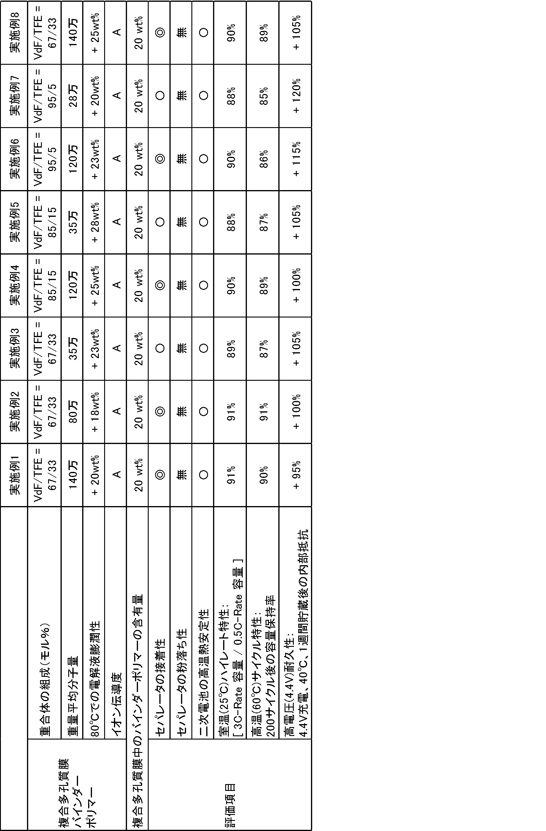

(実施例1~8、比較例1~10の評価)
表1及び2に示すように、本発明のセパレータは、ポリオレフィンセパレータ基材に対して複合多孔質膜が強固に接着して複合多孔質膜の粉落ちもなく、従来のポリオレフィンセパレータ(比較例10)に比べて高温での熱安定性も向上されたものであった。また、二次電池として使用した場合には、良好なハイレート特性と高温サイクル特性を発現し、高電圧保存条件下での耐久性にも優れたものであった(実施例1~8)。複合多孔質膜のバインダーとして、フッ化ビニリデン含有量が35モル%のフッ化ビニリデン-テトラフルオロエチレン共重合体を用いた場合、セパレータ基材に対する複合多孔質膜の接着性が弱く粉落ちが多かった(比較例1)。また、比較例2~4に示すように、重量平均分子量が低いフッ化ビニリデン-テトラフルオロエチレン共重合体を複合多孔質膜のバインダーに用いた場合にも、セパレータ基材に対する複合多孔質膜の接着が不十分であった。比較例1~4のようにセパレータ基材と複合多孔質膜の接着が弱いと、二次電池として充放電サイクルを繰り返した際の容量の低下も大きく、電池としての耐久性が劣っていた。
複合多孔質膜を形成するためのバインダーとしてフッ化ビニリデン-ヘキサフルオロプロピレン共重合体を用いた場合、120℃の高温環境下においてはバインダーポリマー自体がカーボネート系溶媒に溶解してしまうため、高温での熱安定性向上の効果が見られず、電池が短絡する結果となった。さらに、80℃の環境下においても、バインダーポリマーであるフッ化ビニリデン-ヘキサフルオロプロピレン共重合体が電解液に過度に膨潤してしまうことから、電池二次電池として使用した際の高温サイクル特性が著しく低い結果となった(比較例5~6)。
また、複合多孔質膜を形成するためのバインダーとして、ポリフッ化ビニリデンのホモポリマーを用いた場合、バインダー自体のイオン伝導度が本発明のポリフッ化ビニリデン共重合体に比べて低く、テトラフルオロエチレンユニットも導入されていないことから、得られる二次電池はハイレート放電特性および高電圧下での耐久性が劣る結果となった(比較例7)。
さらに、ポリアクリレートやポリアラミドのように極性官能基を含有する非フッ素ポリマーを複合多孔質膜のバインダーとして用いた場合、得られる二次電池は高電圧耐久性に劣るものであった(比較例8~9)。
表1及び2に示すように、本発明のセパレータは、ポリオレフィンセパレータ基材に対して複合多孔質膜が強固に接着して複合多孔質膜の粉落ちもなく、従来のポリオレフィンセパレータ(比較例10)に比べて高温での熱安定性も向上されたものであった。また、二次電池として使用した場合には、良好なハイレート特性と高温サイクル特性を発現し、高電圧保存条件下での耐久性にも優れたものであった(実施例1~8)。複合多孔質膜のバインダーとして、フッ化ビニリデン含有量が35モル%のフッ化ビニリデン-テトラフルオロエチレン共重合体を用いた場合、セパレータ基材に対する複合多孔質膜の接着性が弱く粉落ちが多かった(比較例1)。また、比較例2~4に示すように、重量平均分子量が低いフッ化ビニリデン-テトラフルオロエチレン共重合体を複合多孔質膜のバインダーに用いた場合にも、セパレータ基材に対する複合多孔質膜の接着が不十分であった。比較例1~4のようにセパレータ基材と複合多孔質膜の接着が弱いと、二次電池として充放電サイクルを繰り返した際の容量の低下も大きく、電池としての耐久性が劣っていた。
複合多孔質膜を形成するためのバインダーとしてフッ化ビニリデン-ヘキサフルオロプロピレン共重合体を用いた場合、120℃の高温環境下においてはバインダーポリマー自体がカーボネート系溶媒に溶解してしまうため、高温での熱安定性向上の効果が見られず、電池が短絡する結果となった。さらに、80℃の環境下においても、バインダーポリマーであるフッ化ビニリデン-ヘキサフルオロプロピレン共重合体が電解液に過度に膨潤してしまうことから、電池二次電池として使用した際の高温サイクル特性が著しく低い結果となった(比較例5~6)。
また、複合多孔質膜を形成するためのバインダーとして、ポリフッ化ビニリデンのホモポリマーを用いた場合、バインダー自体のイオン伝導度が本発明のポリフッ化ビニリデン共重合体に比べて低く、テトラフルオロエチレンユニットも導入されていないことから、得られる二次電池はハイレート放電特性および高電圧下での耐久性が劣る結果となった(比較例7)。
さらに、ポリアクリレートやポリアラミドのように極性官能基を含有する非フッ素ポリマーを複合多孔質膜のバインダーとして用いた場合、得られる二次電池は高電圧耐久性に劣るものであった(比較例8~9)。
(実施例9)
実施例1において複合多孔質膜中におけるアルミナ/含フッ素重合体A/カルボキシメチルセルロースの比率を88/10/2(質量%)とした以外は、実施例1と同様の操作を行って、複合多孔質膜スラリー、セパレータ及び二次電池を製造した。
実施例1において複合多孔質膜中におけるアルミナ/含フッ素重合体A/カルボキシメチルセルロースの比率を88/10/2(質量%)とした以外は、実施例1と同様の操作を行って、複合多孔質膜スラリー、セパレータ及び二次電池を製造した。
(実施例10)
実施例1において複合多孔質膜中におけるアルミナ/含フッ素重合体A/カルボキシメチルセルロースの比率を68/30/2(質量%)とした以外は、実施例1と同様の操作を行って、複合多孔質膜スラリー、セパレータ及び二次電池を製造した。
実施例1において複合多孔質膜中におけるアルミナ/含フッ素重合体A/カルボキシメチルセルロースの比率を68/30/2(質量%)とした以外は、実施例1と同様の操作を行って、複合多孔質膜スラリー、セパレータ及び二次電池を製造した。
(比較例11)
実施例1において複合多孔質膜中におけるアルミナ/含フッ素重合体A/カルボキシメチルセルロースの比率を38/60/2(質量%)とした以外は、実施例1と同様の操作を行って、複合多孔質膜スラリー、セパレータ及び二次電池を製造した。
実施例1において複合多孔質膜中におけるアルミナ/含フッ素重合体A/カルボキシメチルセルロースの比率を38/60/2(質量%)とした以外は、実施例1と同様の操作を行って、複合多孔質膜スラリー、セパレータ及び二次電池を製造した。
(比較例12)
実施例1において複合多孔質膜中におけるアルミナ/含フッ素重合体A/カルボキシメチルセルロースの比率を18/80/2(質量%)とした以外は、実施例1と同様の操作を行って、複合多孔質膜スラリー、セパレータ及び二次電池を製造した。
実施例1において複合多孔質膜中におけるアルミナ/含フッ素重合体A/カルボキシメチルセルロースの比率を18/80/2(質量%)とした以外は、実施例1と同様の操作を行って、複合多孔質膜スラリー、セパレータ及び二次電池を製造した。
(比較例13)
実施例1において複合多孔質膜中におけるアルミナ/含フッ素重合体A/カルボキシメチルセルロースの比率を8/90/2(質量%)とした以外は、実施例1と同様の操作を行って、複合多孔質膜スラリー、セパレータ及び二次電池を製造した。
実施例1において複合多孔質膜中におけるアルミナ/含フッ素重合体A/カルボキシメチルセルロースの比率を8/90/2(質量%)とした以外は、実施例1と同様の操作を行って、複合多孔質膜スラリー、セパレータ及び二次電池を製造した。
(比較例14)
実施例4において複合多孔質膜中における含フッ素重合体Dの割合を60質量%とした以外は、実施例4と同様の操作を行って、複合多孔質膜スラリー、セパレータ及び二次電池を製造した。
実施例4において複合多孔質膜中における含フッ素重合体Dの割合を60質量%とした以外は、実施例4と同様の操作を行って、複合多孔質膜スラリー、セパレータ及び二次電池を製造した。
(比較例15)
実施例4において複合多孔質膜中における含フッ素重合体Dの割合を80質量%とした以外は、実施例4と同様の操作を行って、複合多孔質膜スラリー、セパレータ及び二次電池を製造した。
実施例4において複合多孔質膜中における含フッ素重合体Dの割合を80質量%とした以外は、実施例4と同様の操作を行って、複合多孔質膜スラリー、セパレータ及び二次電池を製造した。
(比較例16)
実施例4において複合多孔質膜中における含フッ素重合体Dの割合を90質量%とした以外は、実施例4と同様の操作を行って、複合多孔質膜スラリー、セパレータ及び二次電池を製造した。
実施例4において複合多孔質膜中における含フッ素重合体Dの割合を90質量%とした以外は、実施例4と同様の操作を行って、複合多孔質膜スラリー、セパレータ及び二次電池を製造した。
実施例9及び10、比較例11~16のセパレータ及び二次電池について、実施例1と同様の項目で評価した。その結果を、実施例1及び実施例4とともに表3に示す。

(実施例1、実施例4、実施例9~10、比較例11~16の評価)
表3の比較例11~16に示すように、ポリオレフィンセパレータ基材上に形成された複合多孔質膜中におけるバインダーポリマー(フッ化ビニリデン-テトラフルオロエチレン共重合体)成分の含有量が50質量%よりも多くなると、120℃の高温環境下ではポリオレフィンセパレータ基材とともに複合多孔質膜も熱収縮を起こし、セパレータの熱安定性は向上しない結果となる。一方、実施例1、実施例4、実施例9ならびに実施例10のように、複合多孔質膜中におけるフッ化ビニリデン-テトラフルオロエチレン共重合体の割合を50質量%以下の範囲に設定した場合、高温環境下におけるセパレータの熱収縮を防ぎ、セパレータの熱安定性が向上されていることがわかる。
表3の比較例11~16に示すように、ポリオレフィンセパレータ基材上に形成された複合多孔質膜中におけるバインダーポリマー(フッ化ビニリデン-テトラフルオロエチレン共重合体)成分の含有量が50質量%よりも多くなると、120℃の高温環境下ではポリオレフィンセパレータ基材とともに複合多孔質膜も熱収縮を起こし、セパレータの熱安定性は向上しない結果となる。一方、実施例1、実施例4、実施例9ならびに実施例10のように、複合多孔質膜中におけるフッ化ビニリデン-テトラフルオロエチレン共重合体の割合を50質量%以下の範囲に設定した場合、高温環境下におけるセパレータの熱収縮を防ぎ、セパレータの熱安定性が向上されていることがわかる。
(実施例11)
実施例1の含フッ素重合体Aの作製において、乳化重合後の水性ディスパージョンAにノニオン性界面活性剤としてC13H27O(CH2CH2O)8H(HLB=13.3、曇点=60℃)を加えて、ノニオン性界面活性剤添加後の水性ディスパージョン100質量部に対するノニオンの濃度が0.5質量%の水性ディスパージョンA’を調製した(水性ディスパージョンA’の表面張力値:27mN/m、平均一次粒子径:110nm)。この水性ディスパージョンA’を用いた以外は、実施例1と同様の操作を行って、複合多孔質膜スラリー、セパレータ及び二次電池を製造した。
実施例1の含フッ素重合体Aの作製において、乳化重合後の水性ディスパージョンAにノニオン性界面活性剤としてC13H27O(CH2CH2O)8H(HLB=13.3、曇点=60℃)を加えて、ノニオン性界面活性剤添加後の水性ディスパージョン100質量部に対するノニオンの濃度が0.5質量%の水性ディスパージョンA’を調製した(水性ディスパージョンA’の表面張力値:27mN/m、平均一次粒子径:110nm)。この水性ディスパージョンA’を用いた以外は、実施例1と同様の操作を行って、複合多孔質膜スラリー、セパレータ及び二次電池を製造した。
(実施例12)
実施例1の含フッ素重合体Aの作製において、乳化重合後の水性ディスパージョンAにノニオン性界面活性剤としてC13H27O(CH2CH2O)8H(HLB=13.3、曇点=60℃)を加えて、ノニオン性界面活性剤添加後の水性ディスパージョン100質量部に対するノニオンの濃度が1.0質量%の水性ディスパージョンA’’を調製した(水性ディスパージョンA’’の表面張力値:22mN/m、平均一次粒子径:110nm)。この水性ディスパージョンA’’を用いた以外は、実施例1と同様の操作を行って、複合多孔質膜スラリー、セパレータ及び二次電池を製造した。
実施例1の含フッ素重合体Aの作製において、乳化重合後の水性ディスパージョンAにノニオン性界面活性剤としてC13H27O(CH2CH2O)8H(HLB=13.3、曇点=60℃)を加えて、ノニオン性界面活性剤添加後の水性ディスパージョン100質量部に対するノニオンの濃度が1.0質量%の水性ディスパージョンA’’を調製した(水性ディスパージョンA’’の表面張力値:22mN/m、平均一次粒子径:110nm)。この水性ディスパージョンA’’を用いた以外は、実施例1と同様の操作を行って、複合多孔質膜スラリー、セパレータ及び二次電池を製造した。
(実施例13)
<含フッ素重合体Lの作製>
内容積3Lの攪拌機付きSUS製重合槽に、F(CF2)5COONH4が3300ppmで、かつCH2=CFCF2OCF(CF3)CF2OCF(CF3)COONH4が200ppm濃度の水溶液を入れて密閉した。槽内を真空窒素置換後、真空引きし、連鎖移動剤としてのイソプロピルアルコールをシリンジで400cc相当量を真空吸引しながら仕込んだ。その後、70℃、450rpmで撹拌しながら、槽内にビニリデンフルオライド(VdF)/テトラフルオロエチレン(TFE)組成比が85/15モル%の混合ガスモノマーを、0.8MPaGまで仕込んだ。その後、100ppmに相当する量の過硫酸アンモニウムを溶かした水溶液を窒素で圧入することで反応を開始した。槽内圧力を保持するように、VdF/TFE組成比が85/15モル%の混合モノマーを追加で仕込んだ。追加モノマーが360gになった時点で攪拌を低速にし、槽内ガスを放出して、反応を終了した。槽内を冷却して、ポリマーの固分換算量が20質量%の水性ディスパージョンを得た。この水性ディスパージョンにノニオン性界面活性剤としてC13H27O(CH2CH2O)8H(HLB=13.3、曇点=60℃)を加えて、ノニオン性界面活性剤添加後の水性ディスパージョン100質量部に対するノニオンの濃度が1.0質量%の水性ディスパージョンLを調製した。
なお得られた水性ディスパージョンL中の含フッ素重合体Lは以下の組成及び重量平均分子量を有していた。
VdF/TFE=85.0/15.0(モル%)
重量平均分子量:1200000
融点:124℃
また得られた水性ディスパージョンLは以下の平均一次粒子径及び表面張力を有していた。
平均一次粒子径:115nm
表面張力:20mN/m
<含フッ素重合体Lの作製>
内容積3Lの攪拌機付きSUS製重合槽に、F(CF2)5COONH4が3300ppmで、かつCH2=CFCF2OCF(CF3)CF2OCF(CF3)COONH4が200ppm濃度の水溶液を入れて密閉した。槽内を真空窒素置換後、真空引きし、連鎖移動剤としてのイソプロピルアルコールをシリンジで400cc相当量を真空吸引しながら仕込んだ。その後、70℃、450rpmで撹拌しながら、槽内にビニリデンフルオライド(VdF)/テトラフルオロエチレン(TFE)組成比が85/15モル%の混合ガスモノマーを、0.8MPaGまで仕込んだ。その後、100ppmに相当する量の過硫酸アンモニウムを溶かした水溶液を窒素で圧入することで反応を開始した。槽内圧力を保持するように、VdF/TFE組成比が85/15モル%の混合モノマーを追加で仕込んだ。追加モノマーが360gになった時点で攪拌を低速にし、槽内ガスを放出して、反応を終了した。槽内を冷却して、ポリマーの固分換算量が20質量%の水性ディスパージョンを得た。この水性ディスパージョンにノニオン性界面活性剤としてC13H27O(CH2CH2O)8H(HLB=13.3、曇点=60℃)を加えて、ノニオン性界面活性剤添加後の水性ディスパージョン100質量部に対するノニオンの濃度が1.0質量%の水性ディスパージョンLを調製した。
なお得られた水性ディスパージョンL中の含フッ素重合体Lは以下の組成及び重量平均分子量を有していた。
VdF/TFE=85.0/15.0(モル%)
重量平均分子量:1200000
融点:124℃
また得られた水性ディスパージョンLは以下の平均一次粒子径及び表面張力を有していた。
平均一次粒子径:115nm
表面張力:20mN/m
水性ディスパージョンLを用いた以外は、実施例1と同様の操作を行って、複合多孔質膜スラリー、セパレータ及び二次電池を製造した。
<水性ディスパージョンA’、A’’、Lの振とう・貯蔵安定性評価>
水性ディスパージョンA’、A’’、L 各200ccを250ccのポリエチレン容器にそれぞれ入れて密栓した。恒温振とう機(ヤマト科学社製BT100)を用いて振とう速度120rpm、温度25℃の条件で前記のポリエチレン容器に対して1週間振とうを加えた後、水性ディスパージョン1ccをグラスプレート(4cm×4cm)上に滴下して粗大粒子が発生しているか観察してみたところ、いずれの水性ディスパージョンにおいても肉眼で視認できるような粗大粒子は確認されなかった。また、振とう試験後の水性ディスパージョンの粒子径を動的光散乱式粒子径測定装置(大塚電子株式会社製ELSZ1000)を用いて測定したが、いずれの水性ディスパージョンも1μm以上の粒子径を有する粒子の存在は観測されなかった。さらに、振とう試験後のサンプルを25℃で6ヶ月間静置保存した後に、前述のグラスプレート上へのディスパージョン滴下による目視観察ならびに動的光散乱による粒子径測定を行った場合においても、いずれのサンプルでも1μm以上の粗大粒子の凝集ならびに沈降は生じていないことを確認した。
これらの結果より、界面活性剤を添加した水性ディスパージョンは、振とう安定性に優れ、長期貯蔵時にも粗大粒子の凝集ならびに沈降を生じないことがわかる。
水性ディスパージョンA’、A’’、L 各200ccを250ccのポリエチレン容器にそれぞれ入れて密栓した。恒温振とう機(ヤマト科学社製BT100)を用いて振とう速度120rpm、温度25℃の条件で前記のポリエチレン容器に対して1週間振とうを加えた後、水性ディスパージョン1ccをグラスプレート(4cm×4cm)上に滴下して粗大粒子が発生しているか観察してみたところ、いずれの水性ディスパージョンにおいても肉眼で視認できるような粗大粒子は確認されなかった。また、振とう試験後の水性ディスパージョンの粒子径を動的光散乱式粒子径測定装置(大塚電子株式会社製ELSZ1000)を用いて測定したが、いずれの水性ディスパージョンも1μm以上の粒子径を有する粒子の存在は観測されなかった。さらに、振とう試験後のサンプルを25℃で6ヶ月間静置保存した後に、前述のグラスプレート上へのディスパージョン滴下による目視観察ならびに動的光散乱による粒子径測定を行った場合においても、いずれのサンプルでも1μm以上の粗大粒子の凝集ならびに沈降は生じていないことを確認した。
これらの結果より、界面活性剤を添加した水性ディスパージョンは、振とう安定性に優れ、長期貯蔵時にも粗大粒子の凝集ならびに沈降を生じないことがわかる。
実施例11~13のセパレータ及び二次電池について、実施例1と同様の項目で評価した。その結果を表4に示す。
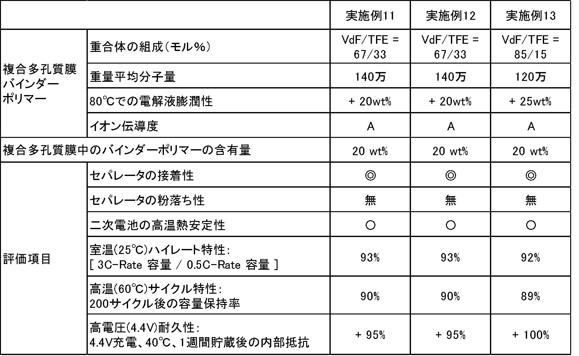
(実施例14)
<含フッ素重合体Mの作製>
内容積1.83Lの攪拌機付きSUS製重合槽に、2級アルカンスルホン酸ナトリウム塩を1.71gと純水を1070g入れて密閉した。槽内を真空窒素置換後、真空引きし、その後、70℃、400rpmで撹拌しながら、槽内にVdF/TFE組成比が65/35モル%の混合ガスモノマーを、0.8MPaGまで仕込んだ。その後、酢酸エチルを0.1g窒素で圧入した。ついで、636ppmに相当する過硫酸アンモニウムを溶かした水溶液を窒素で圧入することで反応を開始した。槽内圧力を保持するように、VdF/TFE組成比が65/35モル%の混合モノマーを追加で仕込んだ。さらに1.5時間ごとに初期の半分量の過硫酸アンモニウムを追加することで反応を継続した。追加モノマーが268gになった時点で攪拌を低速にし、槽内ガスを放出して、反応を終了した。槽内を冷却して、ポリマーの固分換算量が20質量%の水性ディスパージョンを得た。この水性ディスパージョンにアニオン性界面活性剤として2級アルカンスルホン酸ナトリウム塩、ノニオン性界面活性剤としてC13H27O(CH2CH2O)8H(HLB=13.3、曇点=60℃)を加えて、界面活性剤添加後の水性ディスパージョン100質量部に対するアニオンの濃度が0.3質量%、ノニオンの濃度が1.0質量%の水性ディスパージョンMを調製した。
なお得られた水性ディスパージョンM中の含フッ素重合体Mは以下の組成及び重量平均分子量を有していた。
VdF/TFE=67.0/33.0(モル%)
重量平均分子量:230000
また得られた水性ディスパージョンMは以下の平均一次粒子径及び表面張力を有していた。
平均一次粒子径:135nm
表面張力:24mN/m
<含フッ素重合体Mの作製>
内容積1.83Lの攪拌機付きSUS製重合槽に、2級アルカンスルホン酸ナトリウム塩を1.71gと純水を1070g入れて密閉した。槽内を真空窒素置換後、真空引きし、その後、70℃、400rpmで撹拌しながら、槽内にVdF/TFE組成比が65/35モル%の混合ガスモノマーを、0.8MPaGまで仕込んだ。その後、酢酸エチルを0.1g窒素で圧入した。ついで、636ppmに相当する過硫酸アンモニウムを溶かした水溶液を窒素で圧入することで反応を開始した。槽内圧力を保持するように、VdF/TFE組成比が65/35モル%の混合モノマーを追加で仕込んだ。さらに1.5時間ごとに初期の半分量の過硫酸アンモニウムを追加することで反応を継続した。追加モノマーが268gになった時点で攪拌を低速にし、槽内ガスを放出して、反応を終了した。槽内を冷却して、ポリマーの固分換算量が20質量%の水性ディスパージョンを得た。この水性ディスパージョンにアニオン性界面活性剤として2級アルカンスルホン酸ナトリウム塩、ノニオン性界面活性剤としてC13H27O(CH2CH2O)8H(HLB=13.3、曇点=60℃)を加えて、界面活性剤添加後の水性ディスパージョン100質量部に対するアニオンの濃度が0.3質量%、ノニオンの濃度が1.0質量%の水性ディスパージョンMを調製した。
なお得られた水性ディスパージョンM中の含フッ素重合体Mは以下の組成及び重量平均分子量を有していた。
VdF/TFE=67.0/33.0(モル%)
重量平均分子量:230000
また得られた水性ディスパージョンMは以下の平均一次粒子径及び表面張力を有していた。
平均一次粒子径:135nm
表面張力:24mN/m
水性ディスパージョンMを用いた以外は、実施例1と同様の操作を行って、複合多孔質膜スラリー、セパレータ及び二次電池を製造した。
(実施例15)
<含フッ素重合体Nの作製>
内容積1.83Lの攪拌機付きSUS製重合槽に、CH2=CFCF2OCF(CF3)CF2OCF(CF3)COONH4が200ppm濃度の水溶液とパラフィンワックスを10g入れて密閉した。槽内を真空窒素置換後、真空引きし、その後、80℃、400rpmで撹拌しながら、槽内にVdF/TFE組成比が65/35モル%の混合ガスモノマーを、1.15MPaGまで仕込んだ。その後、636ppmに相当する過硫酸アンモニウムを溶かした水溶液を窒素で圧入することで反応を開始した。反応開始より1.5時間ごとに初期の半分量の過硫酸アンモニウムを追加することで反応を継続した。さらに槽内圧力を保持するように、VdF/TFE組成比が65/35モル%の混合モノマーを追加で仕込んだ。追加モノマーが268gになった時点で攪拌を低速にし、槽内ガスをブローして、反応を終了した。槽内を冷却して、ポリマーの固分換算量が20質量%の水性ディスパージョンを得た。この水性ディスパージョンにアニオン性界面活性剤として2級アルカンスルホン酸ナトリウム塩、ノニオン性界面活性剤としてC13H27O(CH2CH2O)8H(HLB=13.3、曇点=60℃)を加えて、界面活性剤添加後の水性ディスパージョン100質量部に対するアニオンの濃度が0.3質量%、ノニオンの濃度が1.0質量%の水性ディスパージョンNを調製した。
なお得られた水性ディスパージョンN中の含フッ素重合体Nは以下の組成及び重量平均分子量を有していた。
VdF/TFE=67.0/33.0(モル%)
重量平均分子量:900000
また得られた水性ディスパージョンNは以下の平均一次粒子径及び表面張力を有していた。
平均一次粒子径:130nm
表面張力:24mN/m
<含フッ素重合体Nの作製>
内容積1.83Lの攪拌機付きSUS製重合槽に、CH2=CFCF2OCF(CF3)CF2OCF(CF3)COONH4が200ppm濃度の水溶液とパラフィンワックスを10g入れて密閉した。槽内を真空窒素置換後、真空引きし、その後、80℃、400rpmで撹拌しながら、槽内にVdF/TFE組成比が65/35モル%の混合ガスモノマーを、1.15MPaGまで仕込んだ。その後、636ppmに相当する過硫酸アンモニウムを溶かした水溶液を窒素で圧入することで反応を開始した。反応開始より1.5時間ごとに初期の半分量の過硫酸アンモニウムを追加することで反応を継続した。さらに槽内圧力を保持するように、VdF/TFE組成比が65/35モル%の混合モノマーを追加で仕込んだ。追加モノマーが268gになった時点で攪拌を低速にし、槽内ガスをブローして、反応を終了した。槽内を冷却して、ポリマーの固分換算量が20質量%の水性ディスパージョンを得た。この水性ディスパージョンにアニオン性界面活性剤として2級アルカンスルホン酸ナトリウム塩、ノニオン性界面活性剤としてC13H27O(CH2CH2O)8H(HLB=13.3、曇点=60℃)を加えて、界面活性剤添加後の水性ディスパージョン100質量部に対するアニオンの濃度が0.3質量%、ノニオンの濃度が1.0質量%の水性ディスパージョンNを調製した。
なお得られた水性ディスパージョンN中の含フッ素重合体Nは以下の組成及び重量平均分子量を有していた。
VdF/TFE=67.0/33.0(モル%)
重量平均分子量:900000
また得られた水性ディスパージョンNは以下の平均一次粒子径及び表面張力を有していた。
平均一次粒子径:130nm
表面張力:24mN/m
水性ディスパージョンNを用いた以外は、実施例1と同様の操作を行って、複合多孔質膜スラリー、セパレータ及び二次電池を製造した。また作製した分散液中のフッ素化界面活性剤の濃度は分散液に対して10ppb以下であった。
<水性ディスパージョンM、Nの振とう・貯蔵安定性評価>
水性ディスパージョンM、N 各200ccを250ccのポリエチレン容器にそれぞれ入れて密栓した。恒温振とう機(ヤマト科学社製BT100)を用いて振とう速度120rpm、温度25℃の条件で前記のポリエチレン容器に対して1週間振とうを加えた後、水性ディスパージョン1ccをグラスプレート(4cm×4cm)上に滴下して粗大粒子が発生しているか観察してみたところ、いずれの水性ディスパージョンにおいても肉眼で視認できるような粗大粒子は確認されなかった。また、振とう試験後の水性ディスパージョンの粒子径を動的光散乱式粒子径測定装置(大塚電子株式会社製ELSZ1000)を用いて測定したが、いずれの水性ディスパージョンも1μm以上の粒子径を有する粒子の存在は観測されなかった。さらに、振とう試験後のサンプルを25℃で6ヶ月間静置保存した後に、前述のグラスプレート上へのディスパージョン滴下による目視観察ならびに動的光散乱による粒子径測定を行った場合においても、いずれのサンプルでも1μm以上の粗大粒子の凝集ならびに沈降は生じていないことを確認した。
これらの結果より、F(CF2)5COONH4のようなパーフルオロアルキル系乳化剤を用いずに乳化重合して得られた水性ディスパージョンにおいても、振とう安定性に優れ、長期貯蔵時にも粗大粒子の凝集ならびに沈降を生じないことがわかる。
水性ディスパージョンM、N 各200ccを250ccのポリエチレン容器にそれぞれ入れて密栓した。恒温振とう機(ヤマト科学社製BT100)を用いて振とう速度120rpm、温度25℃の条件で前記のポリエチレン容器に対して1週間振とうを加えた後、水性ディスパージョン1ccをグラスプレート(4cm×4cm)上に滴下して粗大粒子が発生しているか観察してみたところ、いずれの水性ディスパージョンにおいても肉眼で視認できるような粗大粒子は確認されなかった。また、振とう試験後の水性ディスパージョンの粒子径を動的光散乱式粒子径測定装置(大塚電子株式会社製ELSZ1000)を用いて測定したが、いずれの水性ディスパージョンも1μm以上の粒子径を有する粒子の存在は観測されなかった。さらに、振とう試験後のサンプルを25℃で6ヶ月間静置保存した後に、前述のグラスプレート上へのディスパージョン滴下による目視観察ならびに動的光散乱による粒子径測定を行った場合においても、いずれのサンプルでも1μm以上の粗大粒子の凝集ならびに沈降は生じていないことを確認した。
これらの結果より、F(CF2)5COONH4のようなパーフルオロアルキル系乳化剤を用いずに乳化重合して得られた水性ディスパージョンにおいても、振とう安定性に優れ、長期貯蔵時にも粗大粒子の凝集ならびに沈降を生じないことがわかる。
実施例14~15のセパレータ及び二次電池について、実施例1と同様の項目で評価した。
その結果を表5に示す。F(CF2)5COONH4のような非反応性のフッ素系乳化剤を用いずに乳化重合して得られた水性ディスパージョンにおいても、セパレータの耐熱安定性を向上とともに、電池特性の向上も達成できることがわかる。
その結果を表5に示す。F(CF2)5COONH4のような非反応性のフッ素系乳化剤を用いずに乳化重合して得られた水性ディスパージョンにおいても、セパレータの耐熱安定性を向上とともに、電池特性の向上も達成できることがわかる。
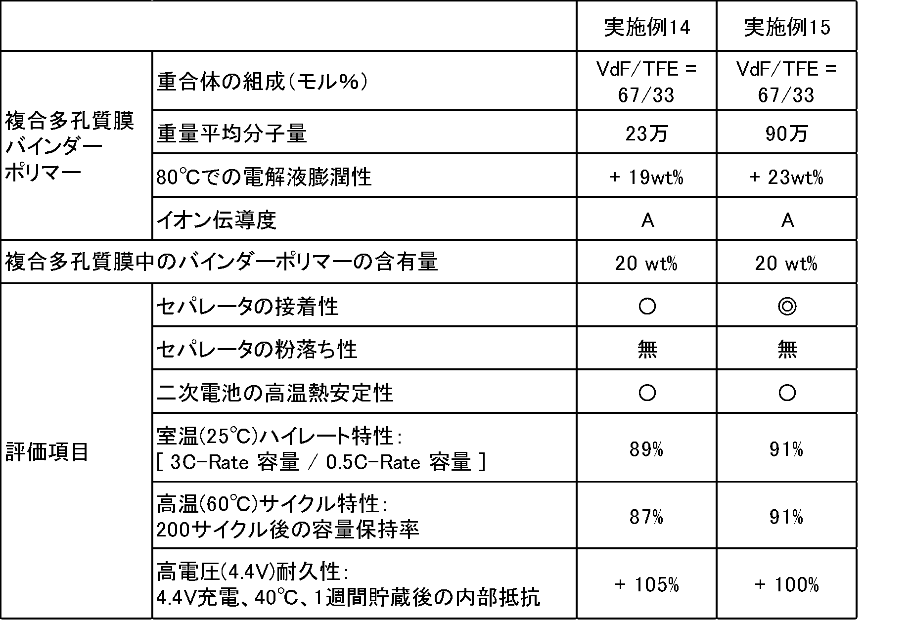
(実施例16)
実施例15で用いた高純度アルミナ粉末(平均粒子径0.013μm)の代わりに、高純度シリカ粉末(平均粒子径0.016μm)を用いたこと以外は、実施例15と同様の操作を行って、複合多孔質膜スラリー、セパレータ及び二次電池を製造した。
実施例15で用いた高純度アルミナ粉末(平均粒子径0.013μm)の代わりに、高純度シリカ粉末(平均粒子径0.016μm)を用いたこと以外は、実施例15と同様の操作を行って、複合多孔質膜スラリー、セパレータ及び二次電池を製造した。
(実施例17)
実施例15において、複合多孔質膜スラリー作製時に架橋ポリメタクリレート(平均粒子径:1μm)を加えて、複合多孔質膜スラリーにおけるアルミナ/架橋ポリメタクリレート(平均粒子径:1μm)/含フッ素重合体N/カルボキシメチルセルロースの比率を65/13/20/2(質量%)とした以外は、実施例15と同様の操作を行って、複合多孔質膜スラリー、セパレータ及び二次電池を製造した。
実施例15において、複合多孔質膜スラリー作製時に架橋ポリメタクリレート(平均粒子径:1μm)を加えて、複合多孔質膜スラリーにおけるアルミナ/架橋ポリメタクリレート(平均粒子径:1μm)/含フッ素重合体N/カルボキシメチルセルロースの比率を65/13/20/2(質量%)とした以外は、実施例15と同様の操作を行って、複合多孔質膜スラリー、セパレータ及び二次電池を製造した。
実施例16~17のセパレータ及び二次電池について、実施例1と同様の項目で評価した。
その結果を表6に示す。
その結果を表6に示す。

本発明の二次電池用セパレータは、多孔性基材と複合多孔質膜の接着性に優れ、電気特性と耐熱性に優れた二次電池を提供することができる。
Claims (5)
- 多孔性基材と、前記多孔性基材上に形成された複合多孔質膜とからなり、
前記複合多孔質膜は、ビニリデンフルオライドに基づく重合単位及びテトラフルオロエチレンに基づく重合単位を含む含フッ素重合体と、金属酸化物粒子および金属水酸化物粒子からなる群より選択される少なくとも1種の無機粒子とを含み、
前記含フッ素重合体は、ビニリデンフルオライドに基づく重合単位を全重合単位中40モル%以上含み、重量平均分子量が20万~200万であり、
前記含フッ素重合体の含有量が、複合多孔質膜中50質量%以下である
ことを特徴とする二次電池用セパレータ。 - 複合多孔質膜は、更に、有機系粒子を含む請求項1記載の二次電池用セパレータ。
- 多孔性基材は、ポリエチレン、ポリプロピレン、ポリイミド、ポリアミド、ポリエチレンテレフタレート、ポリエステルおよびポリアセタールからなる群より選択される少なくとも1種の樹脂からなる請求項1又は2記載の二次電池用セパレータ。
- 無機粒子の含有量は、複合多孔質膜中50~99質量%である請求項1、2又は3記載の二次電池用セパレータ。
- 請求項1、2、3又は4記載の二次電池用セパレータ、正極、負極及び非水電解液を備える二次電池。
Priority Applications (4)
| Application Number | Priority Date | Filing Date | Title |
|---|---|---|---|
| CN201480065508.8A CN105794019A (zh) | 2013-12-06 | 2014-12-04 | 二次电池用隔膜和二次电池 |
| PL14868376T PL3070764T3 (pl) | 2013-12-06 | 2014-12-04 | Separator do baterii akumulatorowej i bateria akumulatorowa |
| KR1020167012603A KR101957000B1 (ko) | 2013-12-06 | 2014-12-04 | 이차 전지용 세퍼레이터 및 이차 전지 |
| EP14868376.6A EP3070764B1 (en) | 2013-12-06 | 2014-12-04 | Separator for secondary battery, and secondary battery |
Applications Claiming Priority (8)
| Application Number | Priority Date | Filing Date | Title |
|---|---|---|---|
| JP2013-253241 | 2013-12-06 | ||
| JP2013253241 | 2013-12-06 | ||
| JP2014-019824 | 2014-02-04 | ||
| JP2014019824 | 2014-02-04 | ||
| JP2014-131691 | 2014-06-26 | ||
| JP2014131691 | 2014-06-26 | ||
| JP2014157052 | 2014-07-31 | ||
| JP2014-157052 | 2014-07-31 |
Publications (1)
| Publication Number | Publication Date |
|---|---|
| WO2015083790A1 true WO2015083790A1 (ja) | 2015-06-11 |
Family
ID=53273538
Family Applications (1)
| Application Number | Title | Priority Date | Filing Date |
|---|---|---|---|
| PCT/JP2014/082118 Ceased WO2015083790A1 (ja) | 2013-12-06 | 2014-12-04 | 二次電池用セパレータ及び二次電池 |
Country Status (7)
| Country | Link |
|---|---|
| EP (1) | EP3070764B1 (ja) |
| JP (1) | JP5757363B1 (ja) |
| KR (1) | KR101957000B1 (ja) |
| CN (2) | CN113067103A (ja) |
| HU (1) | HUE042435T2 (ja) |
| PL (1) | PL3070764T3 (ja) |
| WO (1) | WO2015083790A1 (ja) |
Cited By (6)
| Publication number | Priority date | Publication date | Assignee | Title |
|---|---|---|---|---|
| WO2018216348A1 (ja) * | 2017-05-26 | 2018-11-29 | ダイキン工業株式会社 | 二次電池用セパレータ及び二次電池 |
| US20190013504A1 (en) * | 2016-01-15 | 2019-01-10 | Samsung Sdi Co., Ltd. | Separator for secondary battery and lithium secondary battery comprising same |
| WO2019087652A1 (ja) * | 2017-10-30 | 2019-05-09 | ダイキン工業株式会社 | 二次電池用結着剤、二次電池用電極合剤、二次電池用電極及び二次電池 |
| WO2021002541A1 (ko) * | 2019-07-04 | 2021-01-07 | 삼성에스디아이 주식회사 | 이차 전지용 분리막 및 이를 포함하는 리튬 이차 전지 |
| WO2021161842A1 (ja) * | 2020-02-12 | 2021-08-19 | 日本ゼオン株式会社 | 電気化学素子用積層体及び電気化学素子 |
| CN116231229A (zh) * | 2019-03-18 | 2023-06-06 | 帝人株式会社 | 非水系二次电池用隔膜及非水系二次电池 |
Families Citing this family (25)
| Publication number | Priority date | Publication date | Assignee | Title |
|---|---|---|---|---|
| WO2018124176A1 (ja) * | 2016-12-27 | 2018-07-05 | 東レ株式会社 | 電池用セパレータ、電極体及び非水電解質二次電池 |
| JP6933478B2 (ja) | 2017-03-21 | 2021-09-08 | 株式会社クレハ | ゲル状電解質 |
| JP2018154802A (ja) | 2017-03-21 | 2018-10-04 | 株式会社クレハ | 樹脂組成物、二次電池のセパレータ、および二次電池 |
| WO2019151118A1 (ja) * | 2018-01-31 | 2019-08-08 | 日本ゼオン株式会社 | リチウムイオン二次電池セパレータ用組成物およびリチウムイオン二次電池セパレータ用2液性組成物、並びに、リチウムイオン二次電池用セパレータの製造方法およびリチウムイオン二次電池の製造方法 |
| CN108539095B (zh) * | 2018-04-03 | 2021-06-15 | 上海恩捷新材料科技有限公司 | 电池涂布膜浆料、电池隔膜、二次电池及其制备方法 |
| FR3079834B1 (fr) * | 2018-04-10 | 2021-09-10 | Arkema Inc | Fluoropolymeres fonctionnels |
| TWI803648B (zh) * | 2018-06-12 | 2023-06-01 | 南韓商Lg化學股份有限公司 | 含無機塗層的電化學裝置用之隔板及彼之製造方法 |
| CN112703619A (zh) * | 2018-10-03 | 2021-04-23 | 大金工业株式会社 | 正极结构体和二次电池 |
| TWI821458B (zh) * | 2018-11-19 | 2023-11-11 | 日商大金工業股份有限公司 | 組成物及拉伸體 |
| JP7178948B2 (ja) * | 2019-04-16 | 2022-11-28 | 住友化学株式会社 | 非水電解液二次電池用多孔質層 |
| US20220251251A1 (en) * | 2019-04-26 | 2022-08-11 | Daikin Industries, Ltd. | Fluoropolymer aqueous dispersion production method and fluoropolymer aqueous dispersion |
| WO2021029629A1 (ko) | 2019-08-14 | 2021-02-18 | 주식회사 엘지화학 | 개선된 전극접착력 및 저항 특성을 갖는 리튬이차전지용 분리막 및 상기 분리막을 포함하는 리튬이차전지 |
| JPWO2021172214A1 (ja) * | 2020-02-28 | 2021-09-02 | ||
| CN111192999A (zh) * | 2020-03-14 | 2020-05-22 | 东莞东阳光科研发有限公司 | 一种锂离子电池隔膜及其制备方法 |
| WO2021241689A1 (ja) | 2020-05-28 | 2021-12-02 | 帝人株式会社 | 非水系二次電池用セパレータ及び非水系二次電池 |
| CN116457394A (zh) * | 2020-10-30 | 2023-07-18 | 东京应化工业株式会社 | 聚酰亚胺多孔质膜制造用清漆 |
| JP6954499B1 (ja) * | 2020-11-18 | 2021-10-27 | 昭和電工マテリアルズ株式会社 | リチウムイオン二次電池及び分離膜 |
| JP7587403B2 (ja) * | 2020-11-30 | 2024-11-20 | 株式会社クレハ | フッ化ビニリデン重合体組成物およびその製造方法、樹脂組成物、電極合剤、ならびにこれらを含む電極およびその製造方法 |
| CN116507647B (zh) * | 2020-11-30 | 2025-06-03 | 株式会社吴羽 | 偏氟乙烯共聚物组合物及制造方法、聚合物分散液、非水电解质二次电池用电极、非水电解质二次电池用电解质层、非水电解质二次电池 |
| CN112701420A (zh) * | 2021-01-23 | 2021-04-23 | 山东天瀚新能源科技有限公司 | 锂电池用多功能隔膜、制备方法、应用 |
| JP7721937B2 (ja) * | 2021-03-24 | 2025-08-13 | 富士フイルムビジネスイノベーション株式会社 | ポリイミド多孔質膜、非水系二次電池用セパレータ、二次電池、及び二次電池の製造方法 |
| EP4357377B1 (en) * | 2021-06-18 | 2026-04-08 | Agc Inc. | Method for producing fluorine-containing copolymer |
| CN116144008A (zh) * | 2021-11-23 | 2023-05-23 | 中昊晨光化工研究院有限公司 | 一种稳定剂及其在制备含氟聚合物中的应用 |
| CN117625088A (zh) * | 2022-08-30 | 2024-03-01 | 宁德时代新能源科技股份有限公司 | 粘结剂、制备方法、正极浆料、二次电池及用电装置 |
| KR20260039832A (ko) * | 2024-09-13 | 2026-03-23 | 삼성에스디아이 주식회사 | 리튬 이차 전지용 분리막 및 이를 포함하는 리튬 이차 전지 |
Citations (9)
| Publication number | Priority date | Publication date | Assignee | Title |
|---|---|---|---|---|
| JPH06172452A (ja) | 1992-12-02 | 1994-06-21 | Kureha Chem Ind Co Ltd | フッ化ビニリデン系共重合体 |
| JPH07201316A (ja) | 1993-12-29 | 1995-08-04 | Sony Corp | 非水電解液二次電池 |
| JP2007188777A (ja) * | 2006-01-13 | 2007-07-26 | Sony Corp | セパレータおよび非水電解質電池 |
| JP2008524824A (ja) | 2004-12-22 | 2008-07-10 | エルジー・ケム・リミテッド | 有無機複合多孔性セパレータ膜及び該セパレータ膜を用いる電気化学素子 |
| JP2008266593A (ja) | 2007-03-23 | 2008-11-06 | Sumitomo Chemical Co Ltd | 多孔質フィルム |
| JP2011515799A (ja) | 2008-03-04 | 2011-05-19 | エルジー・ケム・リミテッド | 多孔性コーティング層がコートされたセパレータ及びこれを備えた電気化学素子 |
| WO2011096564A1 (ja) | 2010-02-05 | 2011-08-11 | ダイキン工業株式会社 | 二次電池用ゲル電解質複合フィルム、及び、二次電池 |
| WO2012176815A1 (ja) * | 2011-06-22 | 2012-12-27 | ダイキン工業株式会社 | フルオロポリマー、フルオロポリマーの製造方法、及び、高分子多孔質膜 |
| JP2013219016A (ja) * | 2012-01-24 | 2013-10-24 | Daikin Ind Ltd | 結着剤、正極合剤及び負極合剤 |
Family Cites Families (5)
| Publication number | Priority date | Publication date | Assignee | Title |
|---|---|---|---|---|
| JP5699576B2 (ja) * | 2010-12-08 | 2015-04-15 | ソニー株式会社 | 積層型微多孔膜、電池用セパレータおよび非水電解質電池 |
| US9269938B2 (en) * | 2011-04-08 | 2016-02-23 | Teijin Limited | Separator for nonaqueous secondary battery, and nonaqueous secondary battery |
| JP5853400B2 (ja) * | 2011-04-21 | 2016-02-09 | ソニー株式会社 | セパレータおよび非水電解質電池、ならびに電池パック、電子機器、電動車両、蓄電装置および電力システム |
| WO2013088929A1 (ja) * | 2011-12-16 | 2013-06-20 | 日本電気株式会社 | 二次電池 |
| WO2014065258A1 (ja) * | 2012-10-22 | 2014-05-01 | ダイキン工業株式会社 | セパレータ及び二次電池 |
-
2014
- 2014-12-04 EP EP14868376.6A patent/EP3070764B1/en active Active
- 2014-12-04 CN CN202110310142.8A patent/CN113067103A/zh active Pending
- 2014-12-04 KR KR1020167012603A patent/KR101957000B1/ko active Active
- 2014-12-04 PL PL14868376T patent/PL3070764T3/pl unknown
- 2014-12-04 JP JP2014245724A patent/JP5757363B1/ja active Active
- 2014-12-04 WO PCT/JP2014/082118 patent/WO2015083790A1/ja not_active Ceased
- 2014-12-04 HU HUE14868376A patent/HUE042435T2/hu unknown
- 2014-12-04 CN CN201480065508.8A patent/CN105794019A/zh active Pending
Patent Citations (9)
| Publication number | Priority date | Publication date | Assignee | Title |
|---|---|---|---|---|
| JPH06172452A (ja) | 1992-12-02 | 1994-06-21 | Kureha Chem Ind Co Ltd | フッ化ビニリデン系共重合体 |
| JPH07201316A (ja) | 1993-12-29 | 1995-08-04 | Sony Corp | 非水電解液二次電池 |
| JP2008524824A (ja) | 2004-12-22 | 2008-07-10 | エルジー・ケム・リミテッド | 有無機複合多孔性セパレータ膜及び該セパレータ膜を用いる電気化学素子 |
| JP2007188777A (ja) * | 2006-01-13 | 2007-07-26 | Sony Corp | セパレータおよび非水電解質電池 |
| JP2008266593A (ja) | 2007-03-23 | 2008-11-06 | Sumitomo Chemical Co Ltd | 多孔質フィルム |
| JP2011515799A (ja) | 2008-03-04 | 2011-05-19 | エルジー・ケム・リミテッド | 多孔性コーティング層がコートされたセパレータ及びこれを備えた電気化学素子 |
| WO2011096564A1 (ja) | 2010-02-05 | 2011-08-11 | ダイキン工業株式会社 | 二次電池用ゲル電解質複合フィルム、及び、二次電池 |
| WO2012176815A1 (ja) * | 2011-06-22 | 2012-12-27 | ダイキン工業株式会社 | フルオロポリマー、フルオロポリマーの製造方法、及び、高分子多孔質膜 |
| JP2013219016A (ja) * | 2012-01-24 | 2013-10-24 | Daikin Ind Ltd | 結着剤、正極合剤及び負極合剤 |
Non-Patent Citations (1)
| Title |
|---|
| See also references of EP3070764A4 |
Cited By (16)
| Publication number | Priority date | Publication date | Assignee | Title |
|---|---|---|---|---|
| US20190013504A1 (en) * | 2016-01-15 | 2019-01-10 | Samsung Sdi Co., Ltd. | Separator for secondary battery and lithium secondary battery comprising same |
| KR102261507B1 (ko) * | 2017-05-26 | 2021-06-07 | 다이킨 고교 가부시키가이샤 | 이차 전지용 세퍼레이터 및 이차 전지 |
| WO2018216348A1 (ja) * | 2017-05-26 | 2018-11-29 | ダイキン工業株式会社 | 二次電池用セパレータ及び二次電池 |
| KR20190127963A (ko) * | 2017-05-26 | 2019-11-13 | 다이킨 고교 가부시키가이샤 | 이차 전지용 세퍼레이터 및 이차 전지 |
| JPWO2018216348A1 (ja) * | 2017-05-26 | 2019-11-21 | ダイキン工業株式会社 | 二次電池用セパレータ及び二次電池 |
| US11394083B2 (en) | 2017-05-26 | 2022-07-19 | Daikin Industries, Ltd. | Secondary battery separator including porous film having fluorine-containing polymer of vinylidene fluoride, tetrafluoroethylene, and vinyl carboxylic acid or salt and secondary battery including the same |
| JPWO2019087652A1 (ja) * | 2017-10-30 | 2020-07-09 | ダイキン工業株式会社 | 二次電池用結着剤、二次電池用電極合剤、二次電池用電極及び二次電池 |
| WO2019087652A1 (ja) * | 2017-10-30 | 2019-05-09 | ダイキン工業株式会社 | 二次電池用結着剤、二次電池用電極合剤、二次電池用電極及び二次電池 |
| CN116231229A (zh) * | 2019-03-18 | 2023-06-06 | 帝人株式会社 | 非水系二次电池用隔膜及非水系二次电池 |
| KR102407048B1 (ko) * | 2019-07-04 | 2022-06-08 | 삼성에스디아이 주식회사 | 이차 전지용 분리막 및 이를 포함하는 리튬 이차 전지 |
| KR20210004424A (ko) * | 2019-07-04 | 2021-01-13 | 삼성에스디아이 주식회사 | 이차 전지용 분리막 및 이를 포함하는 리튬 이차 전지 |
| WO2021002541A1 (ko) * | 2019-07-04 | 2021-01-07 | 삼성에스디아이 주식회사 | 이차 전지용 분리막 및 이를 포함하는 리튬 이차 전지 |
| US12374754B2 (en) | 2019-07-04 | 2025-07-29 | Samsung Sdi Co., Ltd. | Separator for secondary battery and lithium secondary battery comprising same |
| JPWO2021161842A1 (ja) * | 2020-02-12 | 2021-08-19 | ||
| WO2021161842A1 (ja) * | 2020-02-12 | 2021-08-19 | 日本ゼオン株式会社 | 電気化学素子用積層体及び電気化学素子 |
| JP7746981B2 (ja) | 2020-02-12 | 2025-10-01 | 日本ゼオン株式会社 | 電気化学素子用積層体及び電気化学素子 |
Also Published As
| Publication number | Publication date |
|---|---|
| HUE042435T2 (hu) | 2019-07-29 |
| EP3070764A1 (en) | 2016-09-21 |
| CN113067103A (zh) | 2021-07-02 |
| PL3070764T3 (pl) | 2019-07-31 |
| JP2016033913A (ja) | 2016-03-10 |
| CN105794019A (zh) | 2016-07-20 |
| EP3070764B1 (en) | 2019-01-30 |
| KR20160071440A (ko) | 2016-06-21 |
| KR101957000B1 (ko) | 2019-03-11 |
| EP3070764A4 (en) | 2017-05-10 |
| JP5757363B1 (ja) | 2015-07-29 |
Similar Documents
| Publication | Publication Date | Title |
|---|---|---|
| JP5757363B1 (ja) | 二次電池用セパレータ及び二次電池 | |
| JP5733314B2 (ja) | 非水系二次電池用正極合剤、それを用いた非水系二次電池用正極および二次電池 | |
| JP6891346B2 (ja) | 接着性組成物、セパレータ構造体、電極構造体、非水電解質二次電池およびその製造方法 | |
| KR20190029653A (ko) | 하이드록실 기를 포함하는 비닐리덴 플루오라이드 공중합체의 플루오린화 계면활성제-무함유 수성 분산물 | |
| US11158907B2 (en) | Nonaqueous electrolyte secondary battery | |
| JPWO2019230140A1 (ja) | ポリマー溶液、これを用いたフィルムの製造方法、および非水電解質二次電池用樹脂組成物 | |
| JPWO2014065258A1 (ja) | セパレータ及び二次電池 | |
| WO2018179698A1 (ja) | コアシェル型粒子ならびにその用途および製造方法 | |
| WO2017110067A1 (ja) | 非水系二次電池多孔膜用バインダー組成物、非水系二次電池多孔膜用スラリー組成物、非水系二次電池用多孔膜、及び非水系二次電池 | |
| JP6874836B2 (ja) | 二次電池用セパレータ及び二次電池 | |
| WO2023182083A1 (ja) | 二次電池用組成物 | |
| JP7853599B2 (ja) | 組成物、ポリマーおよび積層体 | |
| US20190189990A1 (en) | Nonaqueous electrolyte secondary battery | |
| JP7817639B2 (ja) | ポリマー組成物、電気化学デバイス用バインダー、電極合剤、電極、及び、二次電池 | |
| KR102620641B1 (ko) | 비수 전해액 이차 전지 | |
| CN121753143A (zh) | 电化学器件用合剂片材、电化学器件、以及电化学器件用合剂片材的制造方法 | |
| WO2023223607A1 (ja) | 組成物、電気化学デバイス用セパレータ、電気化学デバイスおよび二次電池 | |
| JP2025050544A (ja) | 多孔性フィルム、二次電池用セパレータ、および二次電池 | |
| JP2019145531A (ja) | 非水電解液二次電池の製造方法 |
Legal Events
| Date | Code | Title | Description |
|---|---|---|---|
| 121 | Ep: the epo has been informed by wipo that ep was designated in this application |
Ref document number: 14868376 Country of ref document: EP Kind code of ref document: A1 |
|
| WWE | Wipo information: entry into national phase |
Ref document number: 1020167012603 Country of ref document: KR |
|
| NENP | Non-entry into the national phase |
Ref country code: DE |
|
| REEP | Request for entry into the european phase |
Ref document number: 2014868376 Country of ref document: EP |
|
| WWE | Wipo information: entry into national phase |
Ref document number: 2014868376 Country of ref document: EP |