WO2015087380A1 - Dispositif de radar laser - Google Patents
Dispositif de radar laser Download PDFInfo
- Publication number
- WO2015087380A1 WO2015087380A1 PCT/JP2013/082979 JP2013082979W WO2015087380A1 WO 2015087380 A1 WO2015087380 A1 WO 2015087380A1 JP 2013082979 W JP2013082979 W JP 2013082979W WO 2015087380 A1 WO2015087380 A1 WO 2015087380A1
- Authority
- WO
- WIPO (PCT)
- Prior art keywords
- light
- optical
- transmission
- signal
- pulse
- Prior art date
- Legal status (The legal status is an assumption and is not a legal conclusion. Google has not performed a legal analysis and makes no representation as to the accuracy of the status listed.)
- Ceased
Links
Images




Classifications
-
- G—PHYSICS
- G01—MEASURING; TESTING
- G01S—RADIO DIRECTION-FINDING; RADIO NAVIGATION; DETERMINING DISTANCE OR VELOCITY BY USE OF RADIO WAVES; LOCATING OR PRESENCE-DETECTING BY USE OF THE REFLECTION OR RERADIATION OF RADIO WAVES; ANALOGOUS ARRANGEMENTS USING OTHER WAVES
- G01S7/00—Details of systems according to groups G01S13/00, G01S15/00, G01S17/00
- G01S7/48—Details of systems according to groups G01S13/00, G01S15/00, G01S17/00 of systems according to group G01S17/00
- G01S7/481—Constructional features, e.g. arrangements of optical elements
- G01S7/4811—Constructional features, e.g. arrangements of optical elements common to transmitter and receiver
-
- G—PHYSICS
- G01—MEASURING; TESTING
- G01S—RADIO DIRECTION-FINDING; RADIO NAVIGATION; DETERMINING DISTANCE OR VELOCITY BY USE OF RADIO WAVES; LOCATING OR PRESENCE-DETECTING BY USE OF THE REFLECTION OR RERADIATION OF RADIO WAVES; ANALOGOUS ARRANGEMENTS USING OTHER WAVES
- G01S17/00—Systems using the reflection or reradiation of electromagnetic waves other than radio waves, e.g. lidar systems
- G01S17/02—Systems using the reflection of electromagnetic waves other than radio waves
- G01S17/50—Systems of measurement based on relative movement of target
- G01S17/58—Velocity or trajectory determination systems; Sense-of-movement determination systems
-
- G—PHYSICS
- G01—MEASURING; TESTING
- G01S—RADIO DIRECTION-FINDING; RADIO NAVIGATION; DETERMINING DISTANCE OR VELOCITY BY USE OF RADIO WAVES; LOCATING OR PRESENCE-DETECTING BY USE OF THE REFLECTION OR RERADIATION OF RADIO WAVES; ANALOGOUS ARRANGEMENTS USING OTHER WAVES
- G01S17/00—Systems using the reflection or reradiation of electromagnetic waves other than radio waves, e.g. lidar systems
- G01S17/88—Lidar systems specially adapted for specific applications
- G01S17/95—Lidar systems specially adapted for specific applications for meteorological use
-
- G—PHYSICS
- G01—MEASURING; TESTING
- G01S—RADIO DIRECTION-FINDING; RADIO NAVIGATION; DETERMINING DISTANCE OR VELOCITY BY USE OF RADIO WAVES; LOCATING OR PRESENCE-DETECTING BY USE OF THE REFLECTION OR RERADIATION OF RADIO WAVES; ANALOGOUS ARRANGEMENTS USING OTHER WAVES
- G01S7/00—Details of systems according to groups G01S13/00, G01S15/00, G01S17/00
- G01S7/48—Details of systems according to groups G01S13/00, G01S15/00, G01S17/00 of systems according to group G01S17/00
- G01S7/483—Details of pulse systems
-
- Y—GENERAL TAGGING OF NEW TECHNOLOGICAL DEVELOPMENTS; GENERAL TAGGING OF CROSS-SECTIONAL TECHNOLOGIES SPANNING OVER SEVERAL SECTIONS OF THE IPC; TECHNICAL SUBJECTS COVERED BY FORMER USPC CROSS-REFERENCE ART COLLECTIONS [XRACs] AND DIGESTS
- Y02—TECHNOLOGIES OR APPLICATIONS FOR MITIGATION OR ADAPTATION AGAINST CLIMATE CHANGE
- Y02A—TECHNOLOGIES FOR ADAPTATION TO CLIMATE CHANGE
- Y02A90/00—Technologies having an indirect contribution to adaptation to climate change
- Y02A90/10—Information and communication technologies [ICT] supporting adaptation to climate change, e.g. for weather forecasting or climate simulation
Definitions
- the present invention relates to a laser radar device that remotely measures, for example, the wind direction and wind speed in a weather space.
- pulsed transmission light is transmitted along the scanning optical axis, and the Doppler frequency optical signal included in the reception light based on the transmission light is analyzed to measure the wind speed and the like in the direction of the scanning optical axis.
- a laser radar device is disclosed. This laser radar device includes an analysis circuit that converts a Doppler frequency optical signal into a Doppler frequency electrical signal and analyzes the Doppler frequency electrical signal.
- a light intensity modulation unit is used in the transmitter in order to pulse transmission light.
- AO Acoustic Optic
- carrier leak light is generated due to reverberation of an ultrasonic signal for modulation.
- the carrier leak light induces an unnecessary beat signal in the optical heterodyne receiver. Since this unnecessary beat signal overlaps the Doppler signal to be measured in the frequency domain, there is a disadvantage that the Doppler frequency cannot be estimated correctly.
- Patent Document 1 As a countermeasure, in Patent Document 1, an optical circulator is installed in front of the input end of the light intensity modulation unit, and a total reflection mirror is installed in the rear stage of the output end of the light intensity modulation unit. Thereby, it is possible to reduce the carrier leak light during the pulse OFF period by reciprocating the light intensity modulation unit.
- an AO modulator having a frequency shift function is used for the light intensity modulation unit.
- This AO modulator excites and propagates ultrasonic waves in a medium by applying a high-frequency voltage to a transducer such as a piezo attached to the end face of a glass substrate or acousto-optic crystal.
- a transducer such as a piezo attached to the end face of a glass substrate or acousto-optic crystal.
- a periodic structure with a refractive index is formed and propagates at the velocity of the ultrasonic waves.
- the phase grating moves in a certain direction at the speed of ultrasonic waves.
- the traveling direction of the emitted light not only changes due to Bragg diffraction in the phase grating generated in the medium, but also undergoes Doppler shift as the phase grating moves.
- the high-frequency signal applied to the transducer By turning ON / OFF the high-frequency signal applied to the transducer, it can be cut into pulsed light and at the same time, a certain frequency shift can be added to the pulse ON period.
- Bragg angle ⁇ of the acoustooptic element, the wavelength of light lambda, the offset frequency f ofs, the moving speed v a of the ultrasonic wave in the acousto-optic device is expressed by the following equation.
- the AO modulator used in the above laser radar apparatus has a small Bragg diffraction angle of 1 degree or less. For this reason, in order to optically separate the 0th-order transmitted light and the 1st-order diffracted light, a propagation distance of at least about 30 [mm] is required, which is not suitable for miniaturization. In addition, it is necessary to precisely adjust each of the six axes (translational position and angle) so that the optical axes of the acousto-optic crystal and the incoming / outgoing light coincide with the Bragg diffraction angle, and it is difficult to reduce assembly adjustment costs. .
- the Bragg angle ⁇ changes depending on the light wavelength ⁇ . Further, in order to reduce the optical axis shift (and the accompanying increase in insertion loss) at the input / output end due to the Bragg angle change, it is necessary to control the center wavelength of the reference light source to be constant, which is costly.
- the present invention has been made to solve the above-described problems.
- the device can be reduced in size, integrated, and components.
- An object of the present invention is to provide a laser radar device capable of improving reliability and reducing cost by reducing the number of points.
- a laser radar device includes an optical transmission unit that outputs local oscillation light and transmission light, which are continuous wave light, and transmission light output by the optical transmission unit to space, and backscattered light with respect to the transmission light
- Optical heterodyne receiver that performs optical heterodyne detection using the local oscillation light output by the optical transmission unit and the received light received by the optical antenna, and the detection result by the optical heterodyne receiver
- a laser radar device including a signal processing unit for frequency analysis of the optical transmission unit, wherein the optical transmission unit converts the phase modulation of the continuous wave light into the light phase-modulated by the optical phase modulator.
- a light intensity modulation means that performs pulse modulation to transmit light and a pulse modulation drive signal that periodically repeats the ON / OFF period are generated.
- second signal generating means for driving the optical phase modulator.
- the frequency shift and pulsing necessary on the transmission side are performed without using the AO modulator, thereby reducing the size and integration of the device and reducing the number of components. Improvement and cost reduction can be achieved.
- the timing diagram of each light when the light intensity modulator has an insufficient ON / OFF extinction ratio and the second light intensity modulator is not provided.
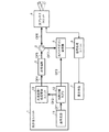
- FIG. 1 is a block diagram showing a configuration of a laser radar apparatus according to Embodiment 1 of the present invention.
- the laser radar apparatus includes an optical transmission unit 1, an optical amplifier 2, an optical circulator 3, an optical antenna unit (optical antenna) 4, an optical heterodyne receiver 5, a signal processing unit 6, and a display means 7.
- thick lines OF1 to OF7 indicate optical signal transmission paths, and thin lines indicate electrical signal transmission paths.
- the optical transmission unit 1 outputs local oscillation light that is continuous oscillation / constant polarization (continuous oscillation light) and transmission light that has been subjected to pulse modulation in which ON / OFF periods are periodically repeated.
- This optical transmission unit includes a reference light source 11, an optical path branching coupler 12, and an optical frequency / intensity modulation unit 13.
- the reference light source 11 generates light having a single wavelength (single frequency) and continuous oscillation and constant polarization.
- the light generated by the reference light source 11 is transmitted to the optical path branching coupler 12 through the transmission path OF1.
- the optical path branching coupler 12 branches the light from the reference light source 11 into two while maintaining the polarization state.
- One light branched into two by this optical path branching coupler 12 is transmitted as local oscillation light to the optical heterodyne receiver 5 via the transmission line OF3, and the other light is transmitted as light as a seed light for transmission via the transmission line OF2. It is transmitted to the frequency / intensity modulation unit 13.
- the optical frequency / intensity modulation unit 13 applies an offset frequency to the light from the optical path branching coupler 12 and performs pulse modulation in which the ON / OFF period is periodically repeated.
- the configuration of the optical frequency / intensity modulation unit 13 will be described later.
- the light subjected to frequency / intensity modulation by the optical frequency / intensity modulation unit 13 is transmitted as transmission light to the optical amplifier 2 through the transmission line OF4.
- the optical amplifier 2 optically amplifies transmission light from the optical frequency / intensity modulation unit 13 of the optical transmission unit 1. At this time, the optical amplifier 2 performs optical amplification by releasing the energy accumulated during the pulse OFF period of the transmission light during the pulse ON period using the accumulation action of the amplification medium.
- the transmission light optically amplified by the optical amplifier 2 is transmitted to the optical circulator 3 through the transmission line OF5.
- the optical circulator 3 switches an output destination transmission path according to input light (transmitted light or received light).
- the optical circulator 3 transmits the transmission light to the optical antenna unit 4 via the transmission path OF6.
- the optical circulator 3 transmits the received light to the optical heterodyne receiver 5 via the transmission path OF7.
- the optical antenna unit 4 emits transmission light transmitted by the optical circulator 3 to a space (observation space) and receives backscattered light from the space with respect to the transmission light as reception light.
- the beam emission direction is set to a specific direction while the transmission light is enlarged to a specific beam diameter, and then emitted to the space.
- the transmission light emitted into the space by the optical antenna unit 4 is backscattered by a scattering target (for example, aerosol moving at the same speed as the wind speed) in the observation space, and undergoes a Doppler frequency shift according to the moving speed of the scattering target. .
- the back scattered light from the scattering target is received by the optical antenna unit 4.
- the received light received by the optical antenna unit 4 is transmitted to the optical circulator 3 through the transmission path OF6.
- the optical heterodyne receiver 5 performs optical heterodyne detection using the local oscillation light from the optical path branching coupler 12 of the optical transmission unit 1 and the reception light from the optical antenna unit 4 via the optical circulator 3. That is, the optical heterodyne receiver 5 optically combines the locally oscillated light and the received light (backscattered light) to perform photoelectric conversion, thereby generating a beat signal having a difference frequency between the backscattered light and the locally oscillated light. Is output. The beat signal output by the optical heterodyne receiver 5 is transmitted to the signal processing unit 6.
- the signal processing unit 6 performs frequency analysis on the beat signal from the optical heterodyne receiver 5. At this time, the signal processing unit 6 first AD-converts the beat signal at a specific sampling rate. Then, the AD converted beat signal is divided for each reception gate (time gate) width corresponding to the pulse width of the transmission light. Then, the beak value, the spectrum width, the SNR, and the like of the power spectrum obtained for each reception gate are calculated by performing fast Fourier transform on the divided beat signals for each reception gate.
- time gate time gate
- the beak value, the spectrum width, the SNR, and the like of the power spectrum obtained for each reception gate are calculated by performing fast Fourier transform on the divided beat signals for each reception gate.
- each reception gate corresponds to the measurement distance, a distribution of Doppler frequency corresponding to the wind speed in the line-of-sight direction for each observation distance can be obtained by the above calculation.
- the signal processing unit 6 has a function of outputting a command value for the observation line of sight to the optical antenna unit 4. Therefore, by storing the measurement values of the observation distance and the wind speed for each line-of-sight direction obtained according to this command value, it is possible to estimate the three-dimensional distribution of the wind speed and obtain the wind direction and the wind speed distribution for each observation distance by vector calculation. .
- the analysis result by the signal processing unit 6 is transmitted to the display means 7.
- the display means 7 displays the analysis result by the signal processing unit 6.
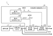
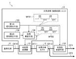
- the optical frequency / intensity modulation unit 13 includes an optical phase modulator 131, an optical intensity modulation unit 132, a first signal generation unit 133, and a second signal generation unit 134.
- the first signal generating unit 133 is connected to the light intensity modulating unit 132
- the second signal generating unit 134 is connected to the optical phase modulator 131.
- the optical phase modulator 131 performs phase modulation on the light from the optical path branching coupler 12 in accordance with the sawtooth drive signal WF02 generated by the second signal generating means 134 to give an offset frequency.
- the transmission light phase-modulated by the optical phase modulator 131 is transmitted to the light intensity modulation means 132 via the transmission line OF8.
- the light intensity modulation unit 132 performs pulse modulation on the light from the optical phase modulator 131 in accordance with the pulse modulation drive signal WF01 generated by the first signal generation unit 133 to generate transmission light.
- the light intensity modulation means 132 responds to the pulse width (several hundreds [ns] to 1 [ ⁇ s]) and the repetition frequency (several [kHz] to several tens [kHz]) required for the laser radar device. Anything is acceptable.
- intensity modulators such as Mach Zehnder type LN modulators and EA (Electro Absorption) modulators
- optical amplifiers such as semiconductor optical amplifiers and optical fiber amplifiers
- optical switches such as MEMS optical switches are conceivable. .
- the first signal generator 133 drives the light intensity modulator 132 by generating a pulse modulation drive signal WF01 that repeats the ON / OFF period periodically required for the transmission light of the pulse type laser radar device. is there.
- the second signal generation means 134 has an amplitude 2 mV ⁇ corresponding to an integral multiple (m times) of the driving voltage 2V ⁇ necessary for obtaining the modulation phase 2 ⁇ (360 °) of the optical phase modulator 131 and a constant period T.
- a sawtooth drive signal WF02 is generated to drive the optical phase modulator 131.
- the reference light source 11 generates light having a single wavelength of continuous oscillation and constant polarization
- the optical path branching coupler 12 converts the light into a polarization state.
- the other is transmitted to the optical heterodyne receiver 5 as local oscillation light, and the other is transmitted to the optical frequency / intensity modulation unit 13 as seed light for transmission.
- the optical frequency / intensity modulation unit 13 assigns an offset frequency f ofs to the light from the optical path branching coupler 12, and performs pulse modulation by periodically repeating the ON / OFF period, thereby transmitting light.
- the frequency ⁇ of light from the optical path branching coupler 12 is 195 [THz]
- the offset frequency f ofs is several tens [MHz] to several hundred ⁇ MHz]
- the pulse width is several hundreds. About [ns] to 1 [ ⁇ s] is used. Details of the operation of the optical frequency / intensity modulation unit 13 will be described later.
- the optical amplifier 2 optically amplifies the light from the optical frequency / intensity modulation unit 13, and the optical antenna unit 4 uses the light as transmission light and expands it to a specific beam diameter while setting the beam emission direction to a specific direction. Set and release into space.
- the transmission light emitted by the optical antenna unit 4 is backscattered by the scattering target in the observation space and undergoes a Doppler frequency shift corresponding to the moving speed of the scattering target.
- the optical antenna unit 4 receives the backscattered light as received light.
- the optical heterodyne receiver 5 performs optical heterodyne detection using the local oscillation light from the optical transmission unit 1 and the reception light from the optical antenna unit 4 via the optical circulator 3. That is, the optical heterodyne receiver 5 optically combines the locally oscillated light and the received light (backscattered light) to perform photoelectric conversion, thereby generating a beat signal having a difference frequency between the backscattered light and the locally oscillated light. Is output.
- the frequency f of the beat signal obtained by the optical heterodyne receiver 5 is expressed by the following equation (1).
- f ofs represents the offset frequency of the optical frequency / intensity modulation unit 13
- f DOP represents the Doppler frequency due to the wind speed.
- the beat signal has a center frequency of 100 [MHz] or less.
- This beat signal is continuously obtained immediately after the transmission light is emitted.
- the distance L to the scattering target can be calculated from the arrival time ⁇ t until the received light is received after the transmitted light is radiated, as shown in the following equation (2).
- c represents the speed of light.
- the signal processing unit 6 performs frequency analysis on the beat signal from the optical heterodyne receiver 5.
- the analysis result by the signal processing unit 6 is stored in a data storage unit (not shown) in the laser radar device, and necessary information is displayed and provided to the user by the display means 7.
- the second signal generating means 134 is an integral multiple (m times) of the drive voltage 2V ⁇ necessary for obtaining the modulation phase 2 ⁇ (360 °) of the optical phase modulator 131.
- a sawtooth drive signal WF02 having a constant period T and an amplitude of 2 mV ⁇ .
- the optical phase modulator 131 performs phase modulation on the transmission light from the optical path branching coupler 12 according to the sawtooth wave drive signal WF02, and gives an offset frequency.
- a phase ⁇ (t) having a constant rate of change 2m ⁇ / T [rad / s] with respect to time t is output from the optical phase modulator 131 as shown in the following equation (3).
- mod (t, T) indicates a remainder when time t is divided by period T.
- the frequency f can be defined by time differentiation of the phase ⁇ as in the following equation (4).
- the optical phase modulator 131 sets the reciprocal of the period T of the sawtooth drive signal WF02 as shown in the following equation (5).
- a proportional offset frequency f ofs can be obtained.
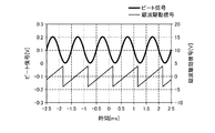
- FIG. 3 shows an actual measurement example of the sawtooth drive signal WF02 input to the optical phase modulator 131 and the beat signal obtained by the optical heterodyne receiver 5 in order to realize a frequency shift of 1 [kHz].
- the lower thin line shows the waveform of the sawtooth drive signal WF02
- the upper thick line shows the waveform of the beat signal.
- the amplitude of the sawtooth drive signal WF02 is set to 7 [V] which is the 2V ⁇ voltage (360 °) of the optical phase modulator 131, and the period T is set to 1 [ms].
- a sine wave having a constant period of 1 [ms] is obtained as a beat signal, and it can be seen that a desired frequency shift of 1 [kHz] is obtained.
- the first signal generating means 133 generates a pulse modulation drive signal WF01 that repeats the OF / OFF period periodically required for the transmission light of the pulse type laser radar device. Then, the light intensity modulation means 132 performs pulse modulation on the light from the optical phase modulator 131 in accordance with the pulse modulation drive signal WF01 to obtain transmission light.
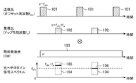
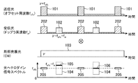
- FIG. 4 shows a timing diagram of each light in the laser radar apparatus according to the first embodiment.
- transmission light 101 having a specific pulse width and repetition period is output by optical phase modulator 131 and light intensity modulation means 132.
- the frequency of the transmission light 101 is represented by ⁇ + f ofs, where ⁇ is the output frequency of the reference light source 11 and f ofs is the offset frequency by the optical phase modulator 131.
- the received light 102 is backscattered light from an aerosol that moves by riding in the air in the atmosphere, and is continuously collected during the pulse OFF period of the transmitted light 101.
- FIG. 4 shows the received light 102 corresponding to a specific distance range for the sake of explanation, it is actually collected continuously during the pulse OFF period of the transmitted light 101.
- Frequency of the received light 102, since the Doppler frequency f w according to the wind velocity is applied is represented by ⁇ + f ofs + f w.
- the local oscillation light 103 is output as a continuous wave in time, and the frequency thereof matches the frequency ⁇ of the reference light source 11.
- the received light 102 and the local oscillation light 103 are optically combined, then photoelectrically converted, and a beat signal f ofs + f having a difference frequency between the reception light 102 and the local oscillation light 103 is obtained.
- Output w .
- the time-series data of the optical heterodyne signal (beat signal) spectrum is obtained as a spectrum detuned by Doppler frequency f w from the center frequency f ofs.
- the optical phase modulator 131 used in the present invention utilizes a change in the refractive index of the propagation optical path due to the electro-optic effect of the LN crystal. Therefore, the propagation effect for the spatial separation of the diffraction effect and the diffracted light as in the AO modulator is unnecessary, and it can contribute to miniaturization and low power consumption. Further, by shortening the propagation length, it is possible to integrate adjacent to the reference light source 11.
- optical phase modulator 131 and the optical intensity modulation means 132 are commercially available with high-speed response (cut-off frequency ⁇ several tens [GHz]) for optical communication. For this reason, it is possible to contribute to improvement in reliability and cost reduction as compared with a conventional configuration using an AO modulator and a modulation driving device that are not widely used for optical communication.
- the diffraction angle changes depending on the frequency (center wavelength) of the reference light source 11, resulting in a change in insertion loss and a line penalty.
- the allowable range for the wavelength variation and wavelength setting range of the reference light source 11 can be expanded. This eliminates the need for equipment for wavelength selection, testing, and stabilization of the reference light source 11 and contributes to cost reduction.
- the blocks inside the optical transmission unit 1 can be integrated into one module by butt joint connection without optical fiber connection.
- an optical circulator and a total reflection mirror for reciprocating the light intensity modulation unit have been required.
- the optical circulator and the total reflection mirror are not necessary, so that the number of parts can be reduced and the cost can be reduced.
- the center frequency of the observation signal matches the center frequency f ofs .
- the transmission light 101 is ideally turned ON / OFF and there is no leakage light during the pulse OFF period. For this reason, the optical heterodyne signal does not include an unnecessary beat signal associated with leaked light. Therefore, the signal processing unit 6, it is only necessary to signal processing by cutting out only the existence range 104 of the Doppler frequency f w filter. Note that the configuration in the case where leakage light in the pulse OFF period exists in the transmission light 101 will be described in detail in the second and subsequent embodiments.
- the optical phase modulator 131 and the light intensity modulator 132 are provided as means for realizing addition of an offset frequency and pulse modulation necessary as functions on the transmission side of the laser radar device. Since the frequency shift and pulsing required on the transmission side without using an AO modulator, the device can be reduced in size and integrated, and the reliability can be improved by reducing the number of parts. Cost reduction can be achieved.
- FIG. 5 is a block diagram showing the configuration of the optical transmission unit 1 according to the second embodiment of the present invention.
- the optical transmission unit 1 according to the second embodiment shown in FIG. 5 is subordinately connected to the optical frequency / intensity modulation unit 13 of the optical transmission unit 1 according to the first embodiment shown in FIG.
- the second light intensity modulation means 135 is added.
- Other configurations are the same, and the same reference numerals are given and only different portions will be described.
- the first signal generation means 133 generates a pulse modulation drive signal WF01 that repeats the OF / OFF period periodically required for the transmission light of the pulse type laser radar device to generate the light intensity modulation means 132 and the second light intensity modulation means 132.
- the light intensity modulating means 135 is driven.
- the second light intensity modulation means 135 performs pulse modulation on the transmission light from the light intensity modulation means 132 in accordance with the pulse modulation drive signal WF01 generated by the first signal generation means 133 to generate transmission light. is there. At this time, the second light intensity modulation unit 135 performs synchronous modulation together with the light intensity modulation unit 132 to suppress leakage light in the pulse OFF period of the transmission light.
- the second light intensity modulating means 135 has a pulse width (several hundreds [ns] to 1 [ ⁇ s]) and a repetition frequency (several [kHz] to several tens [kHz]) required for the laser radar device. Any means for responding can be used. For example, in addition to intensity modulators such as Mach Zehnder type LN modulators and EA modulators, optical amplifiers such as semiconductor optical amplifiers and optical fiber amplifiers, optical switches such as MEMS optical switches, and the like are conceivable.
- FIG. 6 shows a timing diaphragm of each light when the extinction characteristic of the pulse OFF period by the light intensity modulator 23 in the second embodiment is not ideal.
- transmission light 101 having a specific pulse width and repetition period is output during the pulse ON period, while leakage light 201 is output during the pulse OFF period.
- the leaked light 201 is then amplified by the optical amplifier 2. Then, the crosstalk from the transmission path OF5 of the optical circulator 3 to the transmission path OF7, and the reflection of the internal components of the optical antenna unit 4 at the rear stage of the transmission path OF6, the cross of the transmission light 101 (pulse ON period) to the reception optical path.
- the light 202 enters the optical heterodyne receiver 5 as leakage light 203 into the reception optical path of the talk 202 and leakage light 201 (pulse OFF period).
- the leakage light 203 to the reception optical path is a direct light leakage of the transmission light 101 or reflection from a fixed object, the leakage light 203 has the same frequency ⁇ + f ofs as the transmission light 101 (pulse ON period). For this reason, in the optical heterodyne receiver 5, the leakage light 203 to the reception optical path interferes with the local oscillation light 103 to generate an unnecessary beat signal 204.
- This unnecessary beat signal 204 has f ofs which is a difference frequency between the leakage light 203 and the local oscillation light 103 in the reception optical path, and this always exists in time.
- the leakage light 201 in the pulse OFF period is suppressed by synchronously modulating the light intensity modulation means 132 together with the second light intensity modulation means 135.
- FIG. 7 shows a timing diaphragm of each light when the second light intensity modulation unit 135 in the second embodiment is synchronously modulated together with the light intensity modulation unit 132.
- the second light intensity modulation means 135 is synchronously modulated together with the light intensity modulation means 132, so that the leakage light 201 of the transmission light 101 in the pulse OFF period is leaked. Is suppressed.
- the crosstalk 202 to the reception optical path of the transmission light 101 (pulse ON period) and the reception light 102 by wind speed Doppler are obtained as the reception light.
- the optical heterodyne signal spectrum includes the crosstalk 202 of the transmission light 101 (pulse ON period), the beat signal 205 of the local oscillation light 103, and the wind speed. Only the Doppler frequency f w (peak frequency 105, 106, existence range 104) by appears in the spectrum.
- the beat signal 205 between the crosstalk 202 of the transmission light 101 (pulse ON period) and the local oscillation light 103 corresponds to a signal at a distance of 0 m that is not necessary in the laser radar device, and therefore may be rejected in terms of time. .
- the unnecessary beat signal 205 can be suppressed from the optical heterodyne signal spectrum during the pulse OFF period in which wind speed observation is desired, so that accurate wind speed Doppler detection is possible.
- the center frequency increases as the number of stages increases. Therefore, it is necessary to increase the frequency of components used in the optical heterodyne receiver 5 and to increase the signal sampling rate in the signal processing unit 6.
- the center frequency does not change, so that the signal processing at the subsequent stage can be used without change.
- an optical amplifier such as a semiconductor optical amplifier or an optical fiber amplifier may be used for all or a part thereof.
- insertion loss optical path loss
- the laser radar apparatus since a plurality of light intensity modulation means 132 and 135 are connected in cascade to perform synchronous modulation, in addition to the effects of the first embodiment, the laser radar apparatus It is possible to realize a high pulse ON / OFF extinction ratio necessary as performance on the transmission side. Further, since both the light intensity modulation means 132 and the second light intensity modulation means 135 have no wavelength dependence, the tolerance for the wavelength variation of the reference light source 11 and the wavelength setting range compared to the configuration using the conventional AO modulator. The range can be expanded.
- FIG. 8 is a block diagram showing the configuration of the optical transmission unit 1 according to the third embodiment of the present invention.
- the optical transmission unit 1 according to the third embodiment shown in FIG. 8 has signal multiplying means (third signal generating means) added to the optical frequency / intensity modulation unit 13 of the optical transmission unit 1 according to the first embodiment shown in FIG. 136 is added.
- signal multiplying means third signal generating means
- the signal multiplication unit 136 includes a portion corresponding to the pulse ON period of the pulse modulation drive signal WF01 generated by the first signal generation unit 133 in the sawtooth drive signal WF02 generated by the second signal generation unit 134.
- the cut-out sawtooth wave drive signal WF03 is output, and the optical phase modulator 131 is driven in place of the second signal generating means 134.
- the optical phase modulator 131 performs phase modulation on the light from the optical path branching coupler 12 according to the burst-like sawtooth drive signal WF03 output from the signal multiplying unit 136 to give an offset frequency.
- transmission light output from the transmission path OF04 is the pulse ON period is added offset frequency f ofs, not added offset frequency in the pulse OFF periods.
- an offset frequency is added to the leakage light.
- the offset frequency is not added to the leaked light.
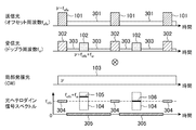
- FIG. 9 shows a timing diagram of each light in the laser radar device according to the third embodiment.
- transmission light 101 having a specific pulse width and repetition period is output during the pulse ON period, while leakage light 301 is output during the pulse OFF period.
- the leaked light 301 is then amplified by the optical amplifier 2. Then, the crosstalk from the transmission path OF5 of the optical circulator 3 to the transmission path OF7, and the reflection of the internal components of the optical antenna unit 4 at the rear stage of the transmission path OF6, the cross of the transmission light 101 (pulse ON period) to the reception optical path.
- the light 302 enters the optical heterodyne receiver 5 as leakage light 303 to the reception optical path of the talk 302 and leakage light 301 (pulse OFF period).
- the frequency of the crosstalk 302 during the pulse ON period is ⁇ + f ofs
- the frequency of the leakage light 303 to the reception optical path of the leakage light 301 (pulse OFF period) is ⁇ because no offset frequency is added to the pulse OFF period. is there.
- an unnecessary beat signal 304 generated by the crosstalk 302 and the local oscillation light 103 during the pulse ON period appears at the f ofs that is the center frequency only during the pulse ON period.
- an unnecessary beat signal 305 generated by the leakage light 303 and the local oscillation light 103 during the pulse OFF period appears in the baseband (frequency 0).
- the Doppler signal (peak frequency 105, the existence range 104) frequency f ofs + f w is away on unwanted beat signals 304, 305 and the spectrum of Therefore, both of them can be electrically separated.
- the pulse modulation drive signal WF01 generated by the first signal generation unit 133 is selected. Since a burst-like sawtooth drive signal cut out from the portion corresponding to the pulse ON period is output, a signal multiplier 136 for driving the optical phase modulator 131 is provided in place of the second signal generator 134.
- the Doppler signal due to the wind speed can be easily separated on the spectrum from the unnecessary beat signals 304 and 305, so that the light intensity modulation is performed.
- the performance requirement for the ON / OFF extinction ratio of the means 132 can be relaxed, which can contribute to cost reduction.
- the combination of burst frequency shift and pulse modulation in the third embodiment is that the conventional AO modulator has a spatial relationship between the output light with the frequency shift added and the output port with no output light added. Therefore, it cannot be realized as it is. That is, a separate means for switching the 0th-order optical output port (without frequency shift) and the first-order optical output port (with frequency shift) of the AO modulator in synchronization with the pulse output is necessary, and an increase in insertion loss or synchronization shift is required.
- the device has a large disadvantage and an increase in power consumption. Further, it is possible to prevent an increase in insertion loss due to the multi-stage light intensity modulation unit as in the conventional example, which contributes to a reduction in power consumption.
- both the light intensity modulation means 132 and the second light intensity modulation means 135 have no wavelength dependency, so that the wavelength of the reference light source 11 is larger than that of the conventional configuration using AO.
- the allowable range with respect to fluctuations and the wavelength setting range can be expanded.
- FIG. 10 is a block diagram showing the configuration of the optical transmission unit 1 according to Embodiment 4 of the present invention.
- the optical transmission unit 1 according to the fourth embodiment illustrated in FIG. 10 is configured such that the position of the optical phase modulator 131 of the optical transmission unit 1 according to the third embodiment illustrated in FIG. 8 is determined between the reference light source 11 and the optical path branching coupler 12. It was changed in between.
- Other configurations are the same, and the same reference numerals are given and only different portions will be described.
- the optical phase modulator 131 performs phase modulation on the light from the reference light source 11 according to the burst sawtooth drive signal WF03 output from the signal multiplier 136 to give an offset frequency.
- the light phase-modulated by the optical phase modulator 131 is transmitted to the optical path branching coupler 12 via the transmission path OF11.
- the optical path branching coupler 12 branches the light from the optical phase modulator 131 into two while maintaining the polarization state.
- the light intensity modulation unit 132 performs pulse modulation on the light from the optical path branching coupler 12 according to the pulse modulation drive signal WF01 generated by the first signal generation unit 133 to generate transmission light.
- the presence / absence change of the offset frequency corresponding to the pulse ON / OFF period is also added to the local oscillation light.
- FIG. 11 shows a timing diagram of each light in the laser radar apparatus according to the fourth embodiment.
- transmission light 101 having a specific pulse width and repetition period is output during the pulse ON period, while leakage light 301 is output during the pulse OFF period.
- the leaked light 301 is then amplified by the optical amplifier 2. Then, the crosstalk from the transmission path OF5 of the optical circulator 3 to the transmission path OF7, and the reflection of the internal components of the optical antenna unit 4 at the rear stage of the transmission path OF6, the cross of the transmission light 101 (pulse ON period) to the reception optical path.
- the light 302 enters the optical heterodyne receiver 5 as leakage light 303 to the reception optical path of the talk 302 and leakage light 301 (pulse OFF period).
- the frequency of the crosstalk 302 during the pulse ON period is ⁇ + f ofs
- the frequency of the leakage light 303 to the reception optical path of the leakage light 301 (pulse OFF period) is ⁇ because no offset frequency is added to the pulse OFF period. is there.
- the frequency of the local oscillation light 103 is ⁇ + f ofs (pulse ON period 401) during the pulse ON period and ⁇ during the pulse OFF period (pulse OFF period 402), as in the transmission light 101. ).
- an unnecessary beat signal 403 generated by the crosstalk 302 in the pulse ON period and the pulse ON period 401 of the local oscillation light 103, and the leaked light 303 and the local oscillation light in the pulse OFF period are generated.
- Any unnecessary beat signal 404 generated by the 103 pulse OFF period 402 appears in the baseband (frequency 0).
- the Doppler signal (peak frequencies 105, 106, existence range 104) due to the wind speed exists near the center frequency.
- the unnecessary beat signals 403 and 404 are separated from each other on the spectrum, so that the two can be electrically separated.
- the phase modulation by the burst-like sawtooth drive signal WF03 synchronized with the transmission light is performed on the transmission light and the local oscillation light.
- the Doppler signal due to the wind speed can be easily separated on the spectrum from the unnecessary beat signals 403 and 404.
- the performance requirement for the ON / OFF extinction ratio can be relaxed, which can contribute to cost reduction.
- the configuration of the fourth embodiment it is possible to shift the unnecessary beat signal 403 in the pulse ON period to the baseband as compared with the configuration of the third embodiment. Therefore, it is possible to avoid the leakage light from being mixed immediately after the pulse OFF period (closest distance range) in the case where a temporal jitter error exists in the pulse timing. For this reason, erroneous detection in wind speed estimation in the closest distance range can be avoided, and wind speed measurement accuracy can be improved.
- both the light intensity modulation means 132 and the second light intensity modulation means 135 have no wavelength dependence, so that the reference light source can be compared with a configuration using a conventional AO modulator.
- the allowable range for the 11 wavelength fluctuations and the wavelength setting range can be expanded.
- Embodiment 5 shows a case where one reference light source 11 and one optical antenna unit 4 are used.
- Embodiment 5 shows a case where the observation space is switched using a plurality of reference light sources 11a and 11b having different wavelengths and a plurality of optical antenna units 4a and 4b corresponding to the respective wavelengths.
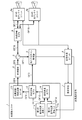
- FIG. 12 is a block diagram showing the configuration of the laser radar apparatus according to Embodiment 5 of the present invention.
- the laser radar device according to the fifth embodiment shown in FIG. 12 includes the reference light source 11 and the optical antenna unit 4 of the laser radar device according to the first embodiment shown in FIG.
- the wavelength branching coupler 8 and the wavelength multiplexing coupler 14 are added to the optical antenna units 4a and 4b.
- Other configurations are the same, and the same reference numerals are given and only different portions will be described.
- the first reference light source 11a generates light that is a continuous wave / constantly polarized light having a center wavelength (frequency) ⁇ 1.
- the light generated by the first reference light source 11a is transmitted to the wavelength multiplexing coupler 14 through the transmission line OF13.
- the second reference light source 11b generates light that is a continuous wave / constantly polarized light having a center wavelength (frequency) ⁇ 2.
- the light generated by the second reference light source 11b is transmitted to the wavelength multiplexing coupler 14 through the transmission line OF14.
- the wavelength multiplexing coupler 14 wavelength-multiplexes the light from the first and second reference light sources 11a and 11b.
- the light wavelength-multiplexed by the wavelength multiplexing coupler 14 is transmitted to the optical path branching coupler 12 via the transmission path OF15.
- the optical path branching coupler 12 branches the light from the wavelength multiplexing coupler 14 into two while maintaining the polarization state.
- the wavelength branching coupler 8 branches the transmission light from the optical circulator 3 for each wavelength.
- the transmission light branched for each wavelength by the wavelength branching coupler 8 is transmitted to the corresponding first and second optical antenna units 4a and 4b via the transmission lines OF17 and OF18.
- the first optical antenna unit 4a corresponds to the first reference light source 11a, emits the transmission light having the center wavelength ⁇ 1 from the wavelength branching coupler 8 into the space, and emits the backscattered light from the space with respect to the transmission light. It is received as received light.
- the received light received by the first optical antenna unit 4a is transmitted to the optical circulator 3 through the transmission lines OF16 and 17.
- the second optical antenna unit 4b corresponds to the second reference light source 11b, emits the transmission light having the center wavelength ⁇ 2 from the wavelength branching coupler 8 to the space, and emits the backscattered light from the space with respect to the transmission light. It is received as received light.
- the received light received by the second optical antenna unit 4b is transmitted to the optical circulator 3 through the transmission lines OF16 and 17.
- FIG. 12 shows an example of a configuration in which the position of the optical path branching coupler 12 is in front of the optical frequency / intensity modulation unit 13 and no frequency shift is given to local oscillation light.
- the present invention is not limited to this.
- the optical path branching coupler 12 is installed after the optical phase modulator 131 driven by the sawtooth drive signal WF03.
- the local oscillation light may be configured to add a frequency shift during the pulse ON period.
- the transmission light output from the optical transmission unit 1 via the transmission line OF4 is amplified by the optical amplifier 2 and passed through the optical circulator 3 as in the configuration of FIG. It is transmitted to the transmission line OF16.
- the transmission light is transmitted from the transmission line OF6 to the wavelength branching coupler 8, and the optical path is switched for each wavelength of the first and second reference light sources 11a and 11b, corresponding to the wavelength ⁇ 1 from the first reference light source 11a.
- the transmitted light is transmitted to the first optical antenna unit 4a, and the light corresponding to the wavelength ⁇ 2 from the second reference light source 11b is transmitted to the second optical antenna unit 4b.
- the observation space can be switched by wavelength switching and measurement can be performed.
- a time-series signal for wavelength selection indicating which one of the first reference light source 11a or the second reference light source 11b is selected at each time is the optical transmission unit 1. Sent to. At the same time, the signal processing unit 6 records and stores the wavelength selection time series signal together with the measured time series data of the Doppler signal. This data is used to identify which one of the first optical antenna unit 4a and the second optical antenna unit 4b is selected in the analysis of the Doppler signal.
- the observation spaces are switched using the plurality of reference light sources 11a and 11b having different wavelengths and the plurality of optical antenna units 4a and 4b corresponding to the respective wavelengths. Since configured, the plurality of optical antenna units 4a and 4b are installed and fixed in advance in different observation spaces, and the observation spaces can be switched by electrically switching the wavelengths. Thereby, the observation space can be switched at high speed without mechanical drive.
- optical antenna units 4a and 4b are fixed at different ground positions with the zenith direction as the center of the field of view, and the optical antenna units 4a and 4b are switched by wavelength switching, so that the height distribution of wind direction and wind speed at two points can be obtained by one laser. It can be measured with a radar device.
- the optical frequency / intensity modulation unit 13 is changed to the wavelength. It was necessary to install every.
- one optical frequency / intensity modulation unit 13 can be used in common. Therefore, the number of parts can be reduced, contributing to cost reduction.
- variable wavelength laser array that has been put into practical use in recent optical communication equipment
- a module in which 12 or more reference light sources and wavelength multiplexing couplers are already integrated is commercially available. Therefore, by using this variable wavelength laser array for optical communication, not only can the element be miniaturized, but also a component that has been tested for reliability as a communication component and has a cost reduction effect due to mass production can be used. Therefore, costs including development costs can be reduced.
- the invention of the present application can be freely combined with each embodiment, modified with any component in each embodiment, or omitted with any component in each embodiment. .
- the laser radar apparatus performs the frequency shift and pulsing necessary on the transmission side without using an AO modulator, thereby reducing the size and integration of the apparatus and improving the reliability and cost by reducing the number of parts.
- it is suitable for use in a laser radar device that remotely measures the wind direction and wind speed in a weather space.
Landscapes
- Engineering & Computer Science (AREA)
- Physics & Mathematics (AREA)
- Computer Networks & Wireless Communication (AREA)
- General Physics & Mathematics (AREA)
- Radar, Positioning & Navigation (AREA)
- Remote Sensing (AREA)
- Electromagnetism (AREA)
- Optical Radar Systems And Details Thereof (AREA)
Abstract
La présente invention concerne une unité de transmission de lumière (1) dotée : d'un modulateur de phase de lumière (131) destiné à une modulation de phase d'une lumière à ondes entretenues ; d'un moyen de modulation d'intensité de lumière (132) destiné à une modulation d'impulsion de la lumière modulée en phase pour générer une lumière de transmission ; d'un premier moyen générateur de signaux (133) destiné à générer un signal de commande modulé en impulsion, qui a des périodes d'activation et de désactivation se répétant de façon périodique, de façon à commander le moyen de modulation d'intensité de lumière (132) ; et d'un second moyen générateur de signaux (134) destiné à générer un signal de commande à ondes en dents de scie de façon à commander le modulateur de phase de lumière (131), ledit signal de commande à ondes en dents de scie ayant une période constante et une amplitude qui équivaut à un nombre entier multiple de la tension de commande nécessaire à l'acquisition d'une phase de modulation de 2n au niveau du modulateur de phase de lumière (131).
Priority Applications (6)
| Application Number | Priority Date | Filing Date | Title |
|---|---|---|---|
| PCT/JP2013/082979 WO2015087380A1 (fr) | 2013-12-09 | 2013-12-09 | Dispositif de radar laser |
| US15/036,252 US10234544B2 (en) | 2013-12-09 | 2014-12-08 | Laser radar device |
| JP2015552446A JP6005302B2 (ja) | 2013-12-09 | 2014-12-08 | レーザレーダ装置 |
| PCT/JP2014/082454 WO2015087842A1 (fr) | 2013-12-09 | 2014-12-08 | Dispositif radar laser |
| CN201480067155.5A CN105814452B (zh) | 2013-12-09 | 2014-12-08 | 激光雷达装置 |
| EP14870467.9A EP3081961B1 (fr) | 2013-12-09 | 2014-12-08 | Dispositif radar laser |
Applications Claiming Priority (1)
| Application Number | Priority Date | Filing Date | Title |
|---|---|---|---|
| PCT/JP2013/082979 WO2015087380A1 (fr) | 2013-12-09 | 2013-12-09 | Dispositif de radar laser |
Publications (1)
| Publication Number | Publication Date |
|---|---|
| WO2015087380A1 true WO2015087380A1 (fr) | 2015-06-18 |
Family
ID=53370729
Family Applications (2)
| Application Number | Title | Priority Date | Filing Date |
|---|---|---|---|
| PCT/JP2013/082979 Ceased WO2015087380A1 (fr) | 2013-12-09 | 2013-12-09 | Dispositif de radar laser |
| PCT/JP2014/082454 Ceased WO2015087842A1 (fr) | 2013-12-09 | 2014-12-08 | Dispositif radar laser |
Family Applications After (1)
| Application Number | Title | Priority Date | Filing Date |
|---|---|---|---|
| PCT/JP2014/082454 Ceased WO2015087842A1 (fr) | 2013-12-09 | 2014-12-08 | Dispositif radar laser |
Country Status (5)
| Country | Link |
|---|---|
| US (1) | US10234544B2 (fr) |
| EP (1) | EP3081961B1 (fr) |
| JP (1) | JP6005302B2 (fr) |
| CN (1) | CN105814452B (fr) |
| WO (2) | WO2015087380A1 (fr) |
Cited By (9)
| Publication number | Priority date | Publication date | Assignee | Title |
|---|---|---|---|---|
| CN105467376A (zh) * | 2016-01-14 | 2016-04-06 | 中国人民解放军空军工程大学 | 大调谐范围线性调频信号产生方法及其装置 |
| JPWO2017134821A1 (ja) * | 2016-02-05 | 2018-07-26 | 三菱電機株式会社 | レーザレーダ装置および風車制御システム |
| WO2019021735A1 (fr) * | 2017-07-28 | 2019-01-31 | 株式会社日立製作所 | Dispositif de production d'énergie éolienne et procédés de commande et de réparation de celui-ci |
| CN110456374A (zh) * | 2019-08-30 | 2019-11-15 | 上海禾赛光电科技有限公司 | 激光雷达的发射电路、激光雷达及激光雷达的测距方法 |
| WO2020079775A1 (fr) * | 2018-10-17 | 2020-04-23 | 日本電気株式会社 | Dispositif de télémétrie et procédé de télémétrie |
| JPWO2021176652A1 (fr) * | 2020-03-05 | 2021-09-10 | ||
| WO2022209789A1 (fr) * | 2021-03-29 | 2022-10-06 | 株式会社小糸製作所 | Dispositif générateur de faisceaux optiques et détecteur optique |
| JP2022173993A (ja) * | 2021-05-10 | 2022-11-22 | オプトウェイヴス インコーポレイテッド | 干渉時間光検出および測距装置 |
| WO2026009542A1 (fr) * | 2024-07-02 | 2026-01-08 | 浜松ホトニクス株式会社 | Dispositif de détection de vitesse du vent, procédé de détection de vitesse du vent et dispositif de commande d'objet volant |
Families Citing this family (47)
| Publication number | Priority date | Publication date | Assignee | Title |
|---|---|---|---|---|
| US9857176B2 (en) * | 2013-06-20 | 2018-01-02 | Tubitak (Turkiye Bilimsel Ve Teknolojik Arastirma Kurumu) | Dynamically monitoring the instantaneous zero rotation rate voltage of interferometric fiber optic gyroscope (IFOG) |
| WO2017009939A1 (fr) * | 2015-07-13 | 2017-01-19 | 三菱電機株式会社 | Dispositif radar à laser |
| WO2017077612A1 (fr) * | 2015-11-05 | 2017-05-11 | 三菱電機株式会社 | Dispositif de radar à laser |
| US10295672B2 (en) * | 2015-11-13 | 2019-05-21 | University Corporation For Atmospheric Research | System and method to measure an atmospheric thermodynamic profile with a compact, all-fiber and eye-safe Lidar |
| JP6544213B2 (ja) * | 2015-11-17 | 2019-07-17 | 株式会社デンソーウェーブ | 窓汚れ判別装置、窓汚れ判別方法、窓汚れ判別プログラム |
| US11204414B2 (en) | 2016-11-02 | 2021-12-21 | Mitsubishi Electric Corporation | Laser radar device |
| JP6223644B1 (ja) * | 2016-12-21 | 2017-11-01 | 三菱電機株式会社 | レーザレーダ装置 |
| JP6654155B2 (ja) * | 2017-01-10 | 2020-02-26 | Kddi株式会社 | 光伝送システム、ponシステムおよび伝送方法 |
| JP6505343B2 (ja) * | 2017-01-24 | 2019-04-24 | 三菱電機株式会社 | レーザレーダ装置 |
| EP3605140B1 (fr) * | 2017-04-13 | 2021-07-07 | Mitsubishi Electric Corporation | Dispositif radar laser |
| JP6743761B2 (ja) | 2017-05-29 | 2020-08-19 | 株式会社デンソー | 測距センサ |
| US10627492B2 (en) | 2017-08-01 | 2020-04-21 | Waymo Llc | Use of extended detection periods for range aliasing detection and mitigation in a light detection and ranging (LIDAR) system |
| CN107942342B (zh) * | 2017-09-29 | 2019-03-22 | 南京牧镭激光科技有限公司 | 测风激光雷达的数据处理方法、装置、系统及存储介质 |
| CN107966691A (zh) * | 2018-01-18 | 2018-04-27 | 北京径科技有限公司 | 一种光学相控阵发射装置 |
| WO2019180924A1 (fr) | 2018-03-23 | 2019-09-26 | 三菱電機株式会社 | Dispositif radar laser |
| US11933903B2 (en) | 2018-03-29 | 2024-03-19 | Mitsubishi Electric Corporation | Laser radar device |
| CN108646230B (zh) * | 2018-05-16 | 2020-12-29 | 北京观详光电技术有限公司 | 一种混合式多普勒激光雷达及其使用方法 |
| CN112236688B (zh) | 2018-06-12 | 2024-03-22 | 三菱电机株式会社 | 光测距装置以及加工装置 |
| US11536805B2 (en) | 2018-06-25 | 2022-12-27 | Silc Technologies, Inc. | Optical switching for tuning direction of LIDAR output signals |
| DE102019211832A1 (de) * | 2018-08-23 | 2020-02-27 | Mitutoyo Corporation | Messvorrichtung und messverfahren |
| US12535586B2 (en) | 2018-08-31 | 2026-01-27 | SiLC Technology, Inc. | Reduction of ADC sampling rates in LIDAR systems |
| US20200116842A1 (en) * | 2018-10-12 | 2020-04-16 | Silc Technologies, Inc. | Optical switching in lidar systems |
| US12015247B2 (en) * | 2018-12-25 | 2024-06-18 | Mitsubishi Electric Corporation | Optical transmission apparatus |
| US11366206B2 (en) * | 2019-03-18 | 2022-06-21 | Aeva, Inc. | Lidar apparatus with an optical amplifier in the return path |
| EP3948340B1 (fr) | 2019-03-29 | 2025-06-18 | Aurora Operations, Inc. | Réseau de pixels cohérents commutables pour la détection et la télémétrie de lumière à onde entretenue modulée en fréquence |
| US11838105B2 (en) * | 2019-05-07 | 2023-12-05 | Infinera Corporation | Bidirectional optical communications |
| US12429569B2 (en) | 2019-05-17 | 2025-09-30 | Silc Technologies, Inc. | Identification of materials illuminated by LIDAR systems |
| US11650317B2 (en) | 2019-06-28 | 2023-05-16 | Silc Technologies, Inc. | Use of frequency offsets in generation of LIDAR data |
| US10802120B1 (en) * | 2019-08-20 | 2020-10-13 | Luminar Technologies, Inc. | Coherent pulsed lidar system |
| GB2586499A (en) * | 2019-08-22 | 2021-02-24 | Thales Holdings Uk Plc | Multi-pixel coherent LIDAR imaging |
| DE102020200348A1 (de) * | 2020-01-14 | 2021-07-15 | Robert Bosch Gesellschaft mit beschränkter Haftung | LiDAR System |
| JP2021156713A (ja) * | 2020-03-26 | 2021-10-07 | 古河電気工業株式会社 | レーダ装置 |
| KR102146052B1 (ko) * | 2020-03-31 | 2020-08-20 | 국방과학연구소 | 채널별 순차 제어를 이용한 광위상배열 기반의 ladar 시스템 및 이의 제어 방법 |
| EP3916424B1 (fr) * | 2020-05-25 | 2024-10-09 | Scantinel Photonics GmbH | Dispositif et procédé de mesure par balayage de la distance à un objet |
| CN112904307A (zh) * | 2021-01-26 | 2021-06-04 | 宁波飞芯电子科技有限公司 | 一种获取距离信息的探测方法及探测系统 |
| EP4266081B1 (fr) * | 2021-01-28 | 2025-08-27 | Mitsubishi Electric Corporation | Dispositif lidar |
| CN116964488A (zh) * | 2021-02-26 | 2023-10-27 | 三菱电机株式会社 | 激光雷达装置 |
| EP4305452A1 (fr) * | 2021-03-10 | 2024-01-17 | Luminar Technologies, Inc. | Système lidar hybride à impulsions/cohérent |
| US11520023B2 (en) | 2021-05-10 | 2022-12-06 | Optowaves, Inc. | High-speed time-of-interference light detection and ranging apparatus |
| US12541009B2 (en) | 2021-06-17 | 2026-02-03 | Silc Technologies, Inc. | Scanning multiple LIDAR system output signals |
| US12411213B2 (en) | 2021-10-11 | 2025-09-09 | Silc Technologies, Inc. | Separation of light signals in a LIDAR system |
| US12553995B2 (en) | 2022-02-14 | 2026-02-17 | Silc Technologies, Inc. | Data refinement in optical systems |
| US12578443B2 (en) | 2022-04-23 | 2026-03-17 | Silc Technologies, Inc. | Data refinement in optical imaging systems |
| US11892566B1 (en) | 2022-09-22 | 2024-02-06 | Optowaves, Inc. | Multiplexed light detection and ranging apparatus |
| US12422618B2 (en) | 2022-10-13 | 2025-09-23 | Silc Technologies, Inc. | Buried taper with reflecting surface |
| US12578439B2 (en) | 2023-04-11 | 2026-03-17 | Silc Technologies, Inc. | Increasing resolution in imaging systems |
| JP2026007101A (ja) * | 2024-07-02 | 2026-01-16 | 浜松ホトニクス株式会社 | 風速検出装置、風速検出方法、及び飛行体制御装置 |
Citations (6)
| Publication number | Priority date | Publication date | Assignee | Title |
|---|---|---|---|---|
| JP2000028705A (ja) * | 1998-07-09 | 2000-01-28 | Mitsubishi Electric Corp | 気象レーダネットワークシステム |
| JP2000193558A (ja) * | 1998-12-28 | 2000-07-14 | Nec Corp | 波長分散測定装置 |
| WO2004061476A1 (fr) * | 2002-12-27 | 2004-07-22 | Mitsubishi Denki Kabushiki Kaisha | Radar laser |
| JP2009027517A (ja) * | 2007-07-20 | 2009-02-05 | Ntt Electornics Corp | 光送信回路 |
| JP2012129514A (ja) * | 2010-11-22 | 2012-07-05 | Canon Inc | 光源装置 |
| WO2013094431A1 (fr) * | 2011-12-21 | 2013-06-27 | 三菱電機株式会社 | Dispositif de radar laser |
Family Cites Families (8)
| Publication number | Priority date | Publication date | Assignee | Title |
|---|---|---|---|---|
| JPH04369421A (ja) | 1991-06-04 | 1992-12-22 | Tokimec Inc | 光ファイバジャイロ |
| JP3681865B2 (ja) * | 1997-03-31 | 2005-08-10 | 三菱電機株式会社 | 光パルス位置検出回路及び光パルス位置検出方法 |
| JP4785475B2 (ja) | 2005-09-20 | 2011-10-05 | 三菱電機株式会社 | レーザレーダ装置 |
| JP4465458B2 (ja) * | 2005-09-20 | 2010-05-19 | 独立行政法人情報通信研究機構 | 位相制御光fsk変調器 |
| US7974534B2 (en) * | 2006-08-11 | 2011-07-05 | Purdue Research Foundation | Wideband microwave and millimeter wave filters using photonic spectral filtering |
| US8558998B2 (en) * | 2008-06-16 | 2013-10-15 | The Regents Of The University Of Colorado, A Body Corporate | Fourier domain sensing |
| JP5542419B2 (ja) * | 2008-11-28 | 2014-07-09 | 三菱電機株式会社 | ドップラーレーダ用受信回路及びドップラーレーダ装置 |
| CN102798866B (zh) * | 2012-08-14 | 2014-05-28 | 哈尔滨工业大学 | 激光雷达系统及采用该系统的正弦调幅-脉冲相位编码调制的复合测距和测速方法 |
-
2013
- 2013-12-09 WO PCT/JP2013/082979 patent/WO2015087380A1/fr not_active Ceased
-
2014
- 2014-12-08 JP JP2015552446A patent/JP6005302B2/ja active Active
- 2014-12-08 US US15/036,252 patent/US10234544B2/en active Active
- 2014-12-08 EP EP14870467.9A patent/EP3081961B1/fr active Active
- 2014-12-08 WO PCT/JP2014/082454 patent/WO2015087842A1/fr not_active Ceased
- 2014-12-08 CN CN201480067155.5A patent/CN105814452B/zh active Active
Patent Citations (6)
| Publication number | Priority date | Publication date | Assignee | Title |
|---|---|---|---|---|
| JP2000028705A (ja) * | 1998-07-09 | 2000-01-28 | Mitsubishi Electric Corp | 気象レーダネットワークシステム |
| JP2000193558A (ja) * | 1998-12-28 | 2000-07-14 | Nec Corp | 波長分散測定装置 |
| WO2004061476A1 (fr) * | 2002-12-27 | 2004-07-22 | Mitsubishi Denki Kabushiki Kaisha | Radar laser |
| JP2009027517A (ja) * | 2007-07-20 | 2009-02-05 | Ntt Electornics Corp | 光送信回路 |
| JP2012129514A (ja) * | 2010-11-22 | 2012-07-05 | Canon Inc | 光源装置 |
| WO2013094431A1 (fr) * | 2011-12-21 | 2013-06-27 | 三菱電機株式会社 | Dispositif de radar laser |
Cited By (13)
| Publication number | Priority date | Publication date | Assignee | Title |
|---|---|---|---|---|
| CN105467376A (zh) * | 2016-01-14 | 2016-04-06 | 中国人民解放军空军工程大学 | 大调谐范围线性调频信号产生方法及其装置 |
| JPWO2017134821A1 (ja) * | 2016-02-05 | 2018-07-26 | 三菱電機株式会社 | レーザレーダ装置および風車制御システム |
| WO2019021735A1 (fr) * | 2017-07-28 | 2019-01-31 | 株式会社日立製作所 | Dispositif de production d'énergie éolienne et procédés de commande et de réparation de celui-ci |
| JPWO2020079775A1 (ja) * | 2018-10-17 | 2021-09-16 | 日本電気株式会社 | 測距装置及び測距方法 |
| WO2020079775A1 (fr) * | 2018-10-17 | 2020-04-23 | 日本電気株式会社 | Dispositif de télémétrie et procédé de télémétrie |
| CN110456374A (zh) * | 2019-08-30 | 2019-11-15 | 上海禾赛光电科技有限公司 | 激光雷达的发射电路、激光雷达及激光雷达的测距方法 |
| CN110456374B (zh) * | 2019-08-30 | 2021-07-06 | 上海禾赛科技股份有限公司 | 激光雷达的发射电路、激光雷达及激光雷达的测距方法 |
| JPWO2021176652A1 (fr) * | 2020-03-05 | 2021-09-10 | ||
| JP7472965B2 (ja) | 2020-03-05 | 2024-04-23 | 日本電気株式会社 | 光測定装置及び光測定方法 |
| WO2022209789A1 (fr) * | 2021-03-29 | 2022-10-06 | 株式会社小糸製作所 | Dispositif générateur de faisceaux optiques et détecteur optique |
| JP2022152115A (ja) * | 2021-03-29 | 2022-10-12 | 株式会社小糸製作所 | 光ビーム生成装置、および光探知機 |
| JP2022173993A (ja) * | 2021-05-10 | 2022-11-22 | オプトウェイヴス インコーポレイテッド | 干渉時間光検出および測距装置 |
| WO2026009542A1 (fr) * | 2024-07-02 | 2026-01-08 | 浜松ホトニクス株式会社 | Dispositif de détection de vitesse du vent, procédé de détection de vitesse du vent et dispositif de commande d'objet volant |
Also Published As
| Publication number | Publication date |
|---|---|
| WO2015087842A1 (fr) | 2015-06-18 |
| EP3081961A1 (fr) | 2016-10-19 |
| US20160291135A1 (en) | 2016-10-06 |
| JP6005302B2 (ja) | 2016-10-12 |
| CN105814452A (zh) | 2016-07-27 |
| CN105814452B (zh) | 2017-12-05 |
| JPWO2015087842A1 (ja) | 2017-03-16 |
| US10234544B2 (en) | 2019-03-19 |
| EP3081961A4 (fr) | 2017-08-30 |
| EP3081961B1 (fr) | 2021-02-17 |
Similar Documents
| Publication | Publication Date | Title |
|---|---|---|
| WO2015087380A1 (fr) | Dispositif de radar laser | |
| JP6223644B1 (ja) | レーザレーダ装置 | |
| CN110383009B (zh) | 光学感测系统及检测光学感测光纤中应力的方法 | |
| JP5738436B2 (ja) | レーザレーダ装置 | |
| JP5654891B2 (ja) | 光ファイバ特性測定装置及び方法 | |
| CN108873007B (zh) | 一种抑制振动效应的调频连续波激光测距装置 | |
| WO2004106971A1 (fr) | Radar a laser coherent | |
| CN116148874B (zh) | 基于光纤分光多视场调频连续波激光雷达测距测速系统 | |
| CN112762970A (zh) | 一种高性能的分布式光纤传感系统及方法 | |
| WO2017090516A1 (fr) | Système de détection de gaz | |
| CN111886513B (zh) | 激光雷达装置 | |
| CN116608936A (zh) | 一种可调分布式光纤传感性能提升装置、传感系统及方法 | |
| CN116106917A (zh) | 一种并行线性调频连续波激光雷达测距测速系统 | |
| CN109557557B (zh) | 一种软件自定义多功能激光雷达 | |
| WO2017077612A1 (fr) | Dispositif de radar à laser | |
| CN116087971B (zh) | 一种opa激光雷达 | |
| Liu et al. | Silicon photonic four-channel dual-polarization coherent receiver module for FMCW LiDAR application | |
| CN116908815A (zh) | 激光雷达及可移动设备 | |
| CN118311589A (zh) | 一种激光雷达 | |
| JP2022145268A (ja) | 距離、速度測定装置及び距離、速度測定方法 | |
| WO2018061106A1 (fr) | Dispositif radar laser | |
| de Chatellus et al. | Laser ranging with analog all-optical coherent pulse compression | |
| CN117368884A (zh) | 一种激光雷达 | |
| JP2013195070A (ja) | テラヘルツ波測定装置 |
Legal Events
| Date | Code | Title | Description |
|---|---|---|---|
| 121 | Ep: the epo has been informed by wipo that ep was designated in this application |
Ref document number: 13899133 Country of ref document: EP Kind code of ref document: A1 |
|
| NENP | Non-entry into the national phase |
Ref country code: DE |
|
| 122 | Ep: pct application non-entry in european phase |
Ref document number: 13899133 Country of ref document: EP Kind code of ref document: A1 |
|
| NENP | Non-entry into the national phase |
Ref country code: JP |