WO2015087706A1 - 誘導システム - Google Patents
誘導システム Download PDFInfo
- Publication number
- WO2015087706A1 WO2015087706A1 PCT/JP2014/081355 JP2014081355W WO2015087706A1 WO 2015087706 A1 WO2015087706 A1 WO 2015087706A1 JP 2014081355 W JP2014081355 W JP 2014081355W WO 2015087706 A1 WO2015087706 A1 WO 2015087706A1
- Authority
- WO
- WIPO (PCT)
- Prior art keywords
- illuminance
- emergency exit
- control device
- unit control
- light emitting
- Prior art date
- Legal status (The legal status is an assumption and is not a legal conclusion. Google has not performed a legal analysis and makes no representation as to the accuracy of the status listed.)
- Ceased
Links
Images


Classifications
-
- G—PHYSICS
- G08—SIGNALLING
- G08B—SIGNALLING SYSTEMS, e.g. PERSONAL CALLING SYSTEMS; ORDER TELEGRAPHS; ALARM SYSTEMS
- G08B7/00—Signalling systems according to two or more of groups G08B3/00 - G08B6/00
- G08B7/06—Signalling systems according to two or more of groups G08B3/00 - G08B6/00 using electric transmission, e.g. involving audible and visible signalling through the use of sound and light sources
- G08B7/066—Signalling systems according to two or more of groups G08B3/00 - G08B6/00 using electric transmission, e.g. involving audible and visible signalling through the use of sound and light sources guiding along a path, e.g. evacuation path lighting strip
-
- H—ELECTRICITY
- H05—ELECTRIC TECHNIQUES NOT OTHERWISE PROVIDED FOR
- H05B—ELECTRIC HEATING; ELECTRIC LIGHT SOURCES NOT OTHERWISE PROVIDED FOR; CIRCUIT ARRANGEMENTS FOR ELECTRIC LIGHT SOURCES, IN GENERAL
- H05B47/00—Circuit arrangements for operating light sources in general, i.e. where the type of light source is not relevant
- H05B47/10—Controlling the light source
- H05B47/105—Controlling the light source in response to determined parameters
-
- H—ELECTRICITY
- H05—ELECTRIC TECHNIQUES NOT OTHERWISE PROVIDED FOR
- H05B—ELECTRIC HEATING; ELECTRIC LIGHT SOURCES NOT OTHERWISE PROVIDED FOR; CIRCUIT ARRANGEMENTS FOR ELECTRIC LIGHT SOURCES, IN GENERAL
- H05B47/00—Circuit arrangements for operating light sources in general, i.e. where the type of light source is not relevant
- H05B47/20—Responsive to malfunctions or to light source life; for protection
-
- G—PHYSICS
- G06—COMPUTING OR CALCULATING; COUNTING
- G06Q—INFORMATION AND COMMUNICATION TECHNOLOGY [ICT] SPECIALLY ADAPTED FOR ADMINISTRATIVE, COMMERCIAL, FINANCIAL, MANAGERIAL OR SUPERVISORY PURPOSES; SYSTEMS OR METHODS SPECIALLY ADAPTED FOR ADMINISTRATIVE, COMMERCIAL, FINANCIAL, MANAGERIAL OR SUPERVISORY PURPOSES, NOT OTHERWISE PROVIDED FOR
- G06Q90/00—Systems or methods specially adapted for administrative, commercial, financial, managerial or supervisory purposes, not involving significant data processing
- G06Q90/20—Destination assistance within a business structure or complex
- G06Q90/205—Building evacuation
Definitions
- the present invention relates to a guidance system, and more particularly to a guidance system that can guide a person to be guided along a guidance path quickly and without anxiety.
- Patent Document 1 As a guidance system for guiding a guided person when a fire or the like occurs, a system disclosed in Patent Document 1 is known.
- an object of the present invention is to provide a guidance system that can guide a guided person quickly and without anxiety along a guidance path.
- the guidance system of the invention of claim 1 includes a plurality of light emitting devices arranged along a passage and a control device for individually controlling the illuminance of each of the plurality of light emitting devices.
- the control device sequentially controls the illuminance of the light emitting device related to the guidance of the plurality of light emitting devices so as to be different from the illuminance of other adjacent light emitting devices at the time of guidance, and the flow of light toward a desired guidance direction Guidance control means for producing
- the control device includes a normal-time control unit that controls the illuminance of the plurality of light emitting devices to a constant illuminance at a normal time. Changes the constant illuminance to another illuminance different from the constant illuminance at the time of guidance, and sets the illuminance of the light emitting device related to the guidance of the plurality of light emitting devices based on the changed illuminance as another reference Control is sequentially performed so as to be different from the illuminance of the light emitting device.
- the guidance control unit changes the constant illuminance to another illuminance lower than the constant illuminance, and the plurality of light emission based on the changed illuminance.
- the illuminance of the light emitting device related to the guidance of the device is sequentially controlled to be higher than the changed illuminance.
- the guidance control unit changes the constant illuminance to another illuminance higher than the constant illuminance, and the plurality of light emission based on the changed illuminance.
- the illuminance of the light emitting device related to the guidance of the device is sequentially controlled to an illuminance lower than the changed illuminance.
- the light-emitting device includes a plurality of light-emitting elements arranged in a line on the floor surface or side surface of the passage.
- the plurality of light emitting devices include a plurality of unit light emitting devices each including a predetermined number of light emitting devices, and the control device includes the unit.
- a plurality of unit control devices provided corresponding to the respective light emitting devices, the unit control device including a plurality of abnormality detection sensors for detecting abnormalities at the locations where the unit control devices are disposed, and an emergency exit when the power is turned on.
- the count values of the plurality of unit control devices along the route toward the vehicle are set and stored in correspondence with the identification information of the emergency exit, and when the abnormality detection sensor detects an abnormality, an abnormality occurrence point by the abnormality detection sensor is avoided.
- Count value setting means for setting and storing the count values of the plurality of unit control devices along the route toward the emergency exit corresponding to the identification information of the emergency exit, and an abnormality has occurred If not, the plurality of light emitting devices of the plurality of unit light emitting devices are controlled to be continuously lit at a constant illuminance, and when an abnormality occurs or when an abnormality is detected by the abnormality detection sensor, the count value setting means stores and stores the The plurality of light emitting devices are sequentially controlled so that the illuminance of each light emitting device related to the guidance of the plurality of light emitting devices of the unit light emitting device is different from the illuminance of another adjacent light emitting device based on the count value of the unit control device. And illuminance control means for generating a flow of light in a desired guiding direction.
- the invention of claim 7 is the invention of claim 6, wherein there are a plurality of the emergency exits, and the count value setting means sequentially receives the count signal from each emergency exit and the plurality of units along the shortest path toward the emergency exit.
- the count value of the control device is set and stored corresponding to the identification information of each emergency exit.
- the invention according to claim 8 is the invention according to claim 6 or 7, wherein the illuminance control means is the emergency exit information and the count value stored in the adjacent unit control device when the abnormality occurs or when the abnormality is detected by the abnormality detection sensor.
- the optical flow start unit control device is determined based on the optical flow start unit control device, the optical flow signal is transmitted from the determined optical flow start unit control device at a predetermined period, and each unit control device that has received the optical flow signal is based on the count value.
- the light flow is generated by sequentially transmitting the light flow signal to the next unit controller.
- the invention of claim 9 is the invention according to any one of claims 6 to 8, wherein the unit control device has buffer means for storing emergency exit information and a count value set and stored in an adjacent unit control device,
- the illuminance control means selects emergency exit information corresponding to the emergency exit having the smallest count value, and when the count value of the unit control device corresponding to the direction away from the emergency exit indicated by the selected emergency exit information is no longer minimum, the buffer means
- the unit control device having the determined illuminance control means is determined as the light flow start unit control device.
- the illuminance control means refers to the information stored in the buffer means if there is no unit control device in a direction away from the emergency exit corresponding to the selected emergency exit information.
- the unit control device having the determined illuminance control means is determined as the light flow start unit control device.
- the guidance system includes a plurality of light emitting devices arranged along a passage, and a control device that individually controls the illuminance of each of the plurality of light emitting devices.
- the guidance control means for sequentially controlling the illuminance of the light emitting device related to the guidance of the plurality of light emitting devices to be different from the illuminance of the other adjacent light emitting devices to generate a flow of light in a desired guidance direction, Since the light-emitting device is continuously lit, a light flow can be created and the guided person can be guided along the guide path quickly and without anxiety.
- FIG. 1 is a block diagram showing an embodiment of a guidance system to which the present invention is applied.
- FIG. 2 is a block diagram showing a configuration example of the unit control device shown in FIG.
- FIG. 3 is a block diagram illustrating a configuration example of the unit light emitting device illustrated in FIG.
- FIG. 4 is a diagram for explaining one operation of the guidance system shown in FIG.
- FIG. 5 is a diagram for explaining another operation of the guidance system shown in FIG.
- FIG. 6 is a diagram for explaining still another operation of the guidance system shown in FIG.
- FIG. 7 is a diagram for explaining still another operation of the guidance system shown in FIG.
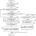
- FIG. 8 is a flowchart for explaining an example of the operation of the guidance system shown in FIG.
- FIG. 9 is a flowchart for explaining the detailed operation of the count value setting process shown in FIG.
- FIG. 10 is a flowchart for explaining the detailed operation of the sequential illuminance control processing shown in FIG.
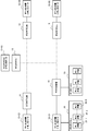
- FIG. 1 is a block diagram showing an embodiment of a guidance system to which the present invention is applied.
- the guidance system shown in FIG. 1 is applicable to, for example, large-scale stores, hospitals, theaters, various facilities, and the like.
- 1 includes a plurality of unit control devices 10, 10-01, 10-02, 10-03, 10-04, 10-05, and these unit control devices 10, 10-01, 10-. 02, 10-03, 10-04, and 10-05, each of which includes a plurality of unit light-emitting devices 20 whose illuminance is controlled.
- the unit control device 10-01 is arranged in the emergency exit in which the emergency exit number 01 is set.
- the unit control device 10-02 is arranged at the emergency exit set with the emergency exit number 02
- the unit control device 10-03 is arranged at the emergency exit set with the emergency exit number 03.
- the unit control device 10-04 is arranged at the emergency exit set with the emergency exit number 04
- the unit control device 10-05 is arranged at the emergency exit set with the emergency exit number 05. is there.
- the other unit control devices 10 are arranged between the unit control devices 10-01, 10-02, 10-03, 10-04, and 10-05 along the passages of the various facilities. is there.
- the unit light emitting device 20 is arranged corresponding to each of the unit control devices 10, 10-01, 10-02, 10-03, 10-04, 10-05, respectively. As shown in FIG.
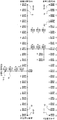
- the eight light emitting devices 20-1 to 20-8 each include a plurality of light emitting elements 21-11 to 1n and 21- 1 arranged in a line. 21-2n, 21-31-3n, 21-41-4n, 21-51-5n, 21-61-6n, 21-71-7n, 21-84-8n.
- These light emitting elements 21-11 to 1n, 21-21 to 2n, 21-31 to 3n, 21-41 to 4n, 21-51 to 5n, 21-61 to 6n, 21-71 to 7n, 21-84 to 8n are arranged in a line along a floor surface, a side surface, or a handrail attached to a side surface of a passage of various facilities, for example.
- 10, 10-01, 10-02, 10-03, 10-04, and 10-05 are mounted on the same substrate and have the same configuration.
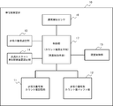
- FIG. 2 is a block diagram showing a configuration example of the unit control device 10 shown in FIG.
- the unit control device 10 includes an emergency exit number-specific count value storage unit 11 that stores a count value corresponding to an emergency exit number in a count value setting process, which will be described in detail later, An emergency exit number count value buffer unit 12 for storing each emergency exit number count value stored in the count value storage unit 11, an emergency exit number setting unit 13 for setting an emergency exit number of the unit control device 10 arranged in the emergency exit, and later
- the light flow start unit control device setting unit 14 for setting the light flow start unit control device determined by the sequential illuminance control processing described in detail, and each of the light emitting devices 20-1 to 20-8 provided in the unit light emitting device 20 are provided.
- the illuminance control unit 15 for controlling the illuminance, and abnormality detection for detecting an abnormality in the arrangement position of the unit control device 10
- a sensor 16 and a control unit 17 that performs overall control of the unit control device 10 are provided.
- the abnormality detection sensor 16 can be configured to include either a temperature detection sensor, a smoke detection sensor, or a combination thereof.
- the control unit 10 sets the count values of the plurality of unit control devices 10 along the path toward the emergency exit to the emergency exit number (identification information) when the power of the unit control device 10 is turned on.
- the setting is stored in the emergency exit number-specific count value storage unit 11, and when an abnormality is detected by the abnormality detection sensor 16 of any of the unit control devices 10, the abnormality detection sensor 16
- a count value setting process is executed for setting and storing the count values of the plurality of unit control devices 10 along the route toward the emergency exit while avoiding the occurrence of an abnormality in the emergency exit number-specific count value storage unit 11 corresponding to the emergency exit number. It has a count value setting means.
- the controller 10 emits light-emitting elements 21-11 to 21- of the plurality of light-emitting devices 20-1 to 20-8 of the plurality of unit display devices 20 when no abnormality has occurred. 1n, 21-21 to 21-2n, 21-31 to 21-3n, 21-41 to 21-4n, 21-51 to 21-5n, 21-61 to 21-6n, 21-71 to 21-7n, The illuminance of 21-81 to 21-8n is controlled to a constant illuminance by the illuminance control unit 15 (normal time control means).
- each light emitting element 21-11 to 21-1n of the plurality of light emitting devices 20-1 to 20-8 when an abnormality is detected by an external abnormality detection device or when an abnormality is detected by the ten abnormality detection sensors 16 of each unit control device, the light emitting elements 21-11 to 21-1n of the plurality of light emitting devices 20-1 to 20-8, 21-21 to 21-2n, 21-31 to 21-3n, 21-41 to 21-4n, 21-51 to 21-5n, 21-61 to 21-6n, 21-71 to 21-7n, 21- After changing all illuminances 81 to 21-8n to predetermined illuminance, each light emitting device 20- related to guidance is based on the count value set and stored in the count value storage unit 11 for each emergency exit number in the count value setting process.
- the illuminance of the light emitting elements 1 to 20-8 is sequentially controlled by the illuminance control unit 15 so as to be different from the illuminance of the other light emitting elements to generate a flow of light in a desired guiding direction.
- an emergency exit Controlling (guidance control unit).
- the control by this guidance control means is, for example, the light emitting elements 21-11 to 21-1n, 21-21 to 21-2n, 21-31 to 21-3n, 21-41 of the light emitting devices 20-1 to 20-8. 21-4n, 21-51 to 21-5n, 21-61 to 21-6n, 21-71 to 21-7n, 21-81 to 21-8n, all luminescence is attenuated to 30% Elements 21-11 to 21-1n, 21-21 to 21-2n, 21-31 to 21-3n, 21-41 to 21-4n, 21-51 to 21-5n, 21-61 to 21-6n, 21 This is done by sequentially controlling the illuminances of ⁇ 71 to 21-7n and 21-81 to 21-8n to 100% in this order. In this case, a light flow with 100% illuminance from the light emitting device 20-1 to the light emitting device 20-8 is formed.
- the illuminance of 21-61 to 21-1n is sequentially controlled to 100% in this order, a light flow with 100% illuminance can be formed from the light emitting device 20-8 to the light emitting device 20-1.
- the illuminance control cycle of 21-6n, 21-71 to 21-7n, 21-81 to 21-8n can be arbitrarily set.
- the illuminance at the time of attenuation of ⁇ 6n, 21-71 to 21-7n, 21-81 to 21-8n and the illuminance at the time of sequential control can be arbitrarily set.
- the illuminance is controlled to 100% sequentially.
- the light flow from the light emitting device 20-1 to the light emitting device 20-8 can be formed even if it is configured so as to be sequentially controlled to 30%.
- the light flow can be reversed as described above, and the light emitting elements 21-11 to 21-1n, 21-21 to 21-2n, 21-31 to 21-3n, 21-- 41 to 21-4n, 21-51 to 21-5n, 21-61 to 21-6n, 21-71 to 21-7n, 21-81 to 21-8n, control cycle of illuminance, increasing illuminance and sequential
- control cycle of illuminance, increasing illuminance and sequential can also be set arbitrarily.
- the illuminance control of 21-5n, 21-61 to 21-6n, 21-71 to 21-7n, 21-81 to 21-8n is controlled by the illuminance control means of the control unit 10.
- the unit control devices 10, 10-01, 10-02, 10-03, 10-04, and 10-05 are connected to each other via a communication line, and the unit control devices 10, 10 are communicated with each other.
- the light flow between ⁇ 01, 10-02, 10-03, 10-04, and 10-05 is configured to flow smoothly.
- FIG. 3 is a block diagram showing a configuration example of the unit light emitting device 20 shown in FIG.
- the unit light emitting device 20 includes, for example, eight light emitting devices 20-1 to 20-8, and each of the light emitting devices 20-1 to 20-8 includes a plurality of lines arranged in a line.
- the unit control device 10-05 transmits a count value “02” obtained by adding “1” to the count value corresponding to the emergency exit number to the adjacent unit control device 10 together with the emergency exit number.
- the adjacent unit control device 10 that has received the emergency exit number and the count value “02” stores the count value “02” in the emergency exit number-specific count value storage unit 11 corresponding to the emergency exit number, and the count value.
- the count value “03” obtained by adding “1” to “02” is transmitted to the next adjacent unit control device 10 together with the emergency exit number.
- the adjacent unit control device 10 that has received the emergency exit number and the count value “03” stores the count value “03” in the emergency exit number-specific count value storage unit 11 corresponding to the emergency exit number.
- the count value “04” obtained by adding “1” to the count value “03” is transmitted to the next adjacent unit control device 10 together with the emergency exit number, and the above operation is repeated.
- the unit controller A in FIG. 4 receives the count value “19” from the unit controller A-1, and receives the count value “21” from the unit controller A + 1. Since the value “19” is smaller than the count value “21”, the unit controller A leaves the count value “19”, discards the count value “21”, and the unit controller A + 1 has the count value “22”. Do not send.
- the minimum number of unit control devices 10 up to the emergency exit corresponding to each emergency exit number corresponds to each emergency exit number as the count value. Will be remembered.
- each unit controller 10 counts by emergency exit number stored in the emergency exit number count value storage unit 11 and the emergency unit number count of the adjacent unit control device 10 stored in the emergency exit number count value buffer unit 12. Based on the value, the light flow start unit control device 10 which is the start of the light flow for guiding the guided person to the emergency exit is determined.
- the determination of the light flow start unit controller 10 is performed as follows.
- this unit control device 10 is used as the light flow start unit control device 10 toward the emergency exit of the selected emergency exit number. decide.
- a unit controller indicated by a double circle indicates a unit controller determined as the light flow start unit controller (the same applies to FIGS. 5, 6, and 7).
- the emergency exit number “05” with the count value “12” is selected as the emergency exit number with the smallest count value, but the count value with the emergency exit number “05” is large. Since there is no adjacent unit control device in the direction, the unit control device S1 is determined as the light flow start unit control device toward the emergency exit whose emergency exit number is “05”.
- emergency exit numbers “01” and “05” having a count value of “11” are selected as the emergency exit number having the smallest count value.
- the selected emergency exit number “01” is selected.
- the count value in the adjacent unit control device in the direction in which the count value increases is “12”, which is less than the count value corresponding to the other emergency exit numbers.
- the light flow start unit control device toward the emergency exit of “01” is determined, and the count value of the adjacent unit control device in the direction in which the count value of the selected emergency exit number “05” increases is “12”.
- the unit control device S2 does not have a minimum value compared with the count value corresponding to the number, so that the unit controller S2 starts the light flow toward the emergency exit with the emergency exit number “05”. It is also determined as a control device.
- the emergency exit numbers “03”, “04”, and “05” with the count value “11” are selected as the emergency exit number with the smallest count value. Further, the count value in the adjacent unit control device in the direction in which the count value of the emergency exit number “03” increases is “12”, which is not minimum compared with the count values corresponding to the other emergency exit numbers.
- the unit control device S3 is determined as the light flow start unit control device toward the emergency exit of the emergency exit number “03”, and the count value in the adjacent unit control device in the direction in which the count value of the selected emergency exit number “04” increases is “ The unit control device S3 goes to the emergency exit whose emergency exit number is “04” because it is no smaller than the count value corresponding to the other emergency exit numbers at “12”. It is also determined as the light flow start unit control device, and the count value in the adjacent unit control device in the direction in which the count value of the selected emergency exit number “05” increases is “12”, which corresponds to another emergency exit number. The unit control device S3 is also determined as a light flow start unit control device toward the emergency exit whose emergency exit number is “05” because it is not minimum compared with the count value.
- the emergency exit numbers “02” and “05” with the count value “13” are selected as the emergency exit numbers with the smallest count value.
- the count value in the adjacent unit control device in the direction in which the count value of “02” increases is “14”, which is not minimum as compared with the count values corresponding to other emergency exit numbers.
- the count value in the adjacent unit control device in the direction in which the count value of the selected emergency exit number “05” increases is determined as “14” as the light flow start unit control device toward the emergency exit number “02”. Since the unit control device S4 becomes less than the count value corresponding to the other emergency exit number, the unit control device S4 performs the light flow flow toward the emergency exit with the emergency exit number “05”. It is also determined as over Units controller.
- emergency exit numbers “02” and “03” having a count value of “07” are selected as the emergency exit number having the smallest count value.
- the count value in the adjacent unit control device in the direction in which the count value of “02” increases is “08”, which is not minimum compared with the count values corresponding to other emergency exit numbers.
- the count value in the adjacent unit control device in the direction in which the count value of the selected emergency exit number “03” increases is “08”, determined as the light flow start unit control device toward the emergency exit number “02”. Since the unit control device S5 is not minimum compared with the count values corresponding to the other emergency exit numbers, the unit control device S5 performs the light flow scanning toward the emergency exit with the emergency exit number “03”. It is also determined as over Units controller.
- the emergency exit numbers “04” and “05” having the count value “08” are selected as the emergency exit number having the smallest count value.
- the count value in the adjacent unit control device in the direction in which the count value of “04” increases is “09”, which is not minimum compared with the count values corresponding to other emergency exit numbers.
- the count value in the adjacent unit control device in the direction in which the count value of the selected emergency exit number “05” increases is “09”, determined as the light flow start unit control device toward the emergency exit number “04”. Since the unit control device S5 is not minimum compared with the count values corresponding to other emergency exit numbers, the unit control device S5 performs the light flow scanning toward the emergency exit with the emergency exit number “05”. It is also determined as over Units controller.
- each unit control device 10 sequentially transfers this light flow signal to the unit control devices 10 adjacent in the direction toward each emergency exit, thereby forming a light flow that guides the person to be guided to the nearest emergency exit.
- the arrow described corresponding to each unit control device 10 indicates the direction of light flow that guides this person to the nearest emergency exit.
- FIG. 5 shows an operation when an abnormality occurs in any one of the plurality of unit control devices 10 and an abnormality is detected by the abnormality detection sensor 16 of the unit control device 10. is there.
- FIG. 5 shows an operation when an abnormality occurs in the unit control device P1 of the plurality of unit control devices 10 and an abnormality is detected by the abnormality detection sensor 16 of the unit control device P1.
- the abnormality detection signal detected by the abnormality detection sensor 16 of the unit control device P1 is transmitted to the unit control device 10 disposed at each emergency exit through each unit control device 10.
- the unit control unit 10 adjoins the count value “02” obtained by adding “1” to the count value corresponding to the emergency exit number together with the emergency exit number.
- Each unit control device 10 transmits the count value of the plurality of unit control devices 10 along the route to the emergency exit to the count value storage for each emergency exit number corresponding to the emergency exit number (identification information).
- the count value setting process set and stored in the unit 11 is executed again.
- the unit control device P1 since the unit control device P1 does not send the count value to the adjacent unit control device 10, the stored content of the count value storage unit 11 for each emergency exit number of each unit control device P1 is the count value shown in parentheses in FIG. To be rewritten.
- the emergency exit number-specific count value storage unit 11 of each unit control device 10 avoids the unit control device P1 in which an abnormality has occurred, and corresponds to each emergency exit number up to the emergency exit corresponding to each emergency exit number.
- the minimum number of unit control devices 10 is stored as a count value.
- each unit controller 10 counts by emergency exit number stored in the emergency exit number count value storage unit 11 and the emergency unit number count of the adjacent unit control device 10 stored in the emergency exit number count value buffer unit 12. Based on the value, the light flow start unit control device 10 which is the start of the light flow for guiding the guided person to the emergency exit is determined.
- the determination method of the light flow start unit control device 10 is the same as the method described in FIG.
- each unit control device 10 After the determination of the light flow start unit control device 10, a light flow signal directed from the light flow start unit control device to each emergency exit is transmitted. Accordingly, each unit control device 10 sequentially transfers this light flow signal to the unit control devices 10 adjacent in the direction toward each emergency exit, thereby each light emitting device of the unit light emitting device 20 corresponding to each unit control device 10.
- a plurality of light emitting elements 21-11 to 21-1n, 21-21 to 21-2n, 21-31 to 21-3n, 21-41 to 21-4n, 21-51 provided in 20-1 to 20-8 21-5n, 21-61 to 21-6n, 21-71 to 21-7n, 21-81 to 21-8n to control the illuminance in order to guide the person to the nearest emergency exit.
- the arrow described corresponding to each unit control device 10 indicates the direction of light flow that guides this person to the nearest emergency exit.
- a plurality of light emitting elements 21-11 to 21-1n, 21-21 to 21-2n, 21-31 to 21-3n, 21-41 to 21-4n, 21-51 to 21- 5n, 21-61 to 21-6n, 21-71 to 21-7n, 21-81 to 21-8n are continuously lit at a constant illuminance, but when an abnormality is detected by the abnormality detection sensor 16 of the unit controller P1, A plurality of light emitting elements 21-11 to 21-1n, 21-21 to 21-2n, 21-31 provided in each light emitting device 20-1 to 20-8 of the unit light emitting device 20 corresponding to each unit control device 10.
- FIG. 6 shows the operation when an abnormality occurs in the unit control device P2, and the abnormality detection sensor 16 of the unit control device P2 detects an abnormality.
- FIG. 6 An operation when an abnormality occurs in the control device P3 and an abnormality is detected by the abnormality detection sensor 16 of the unit control device P3 is shown.
- the operation of the specific example shown in FIG. 6 and the specific example shown in FIG. 7 is the same as the operation of the specific example shown in FIG. 5 except that the position of the abnormality occurrence unit control device 10 is different.
- FIG. 8 is a flowchart for explaining an example of the operation of the guidance system shown in FIG.
- step 801 it is checked whether the power of the evacuation guidance system is turned on. If the power is not turned on (NO in step 801), the process returns to step 801. If it is determined in step 801 that the power is turned on (YES in step 801), each light emission of the unit light emitting device 20 is performed.
- the plurality of light emitting elements 21-11 to 21-1n, 21-21 to 21-2n, 21-31 to 21-3n, 21-41 to 21-4n, 21- 1 provided in the devices 20-1 to 20-8 51 to 21-5n, 21-61 to 21-6n, 21-71 to 21-7n, 21-81 to 21-8n are continuously lit to operate as a night light (step 802).
- a count value setting process is executed (step 900).
- the count value from the emergency exit of each unit control device 10 along the path toward the emergency exit corresponds to the emergency exit number (identification information) and the count value storage unit 11 for each emergency exit number.
- the details of the count value setting process will be described later with reference to FIG.
- step 803 it is checked whether an external device (not shown) that is installed outside checks whether an abnormality is detected by the abnormality detection sensor 16 of the unit control device 10 (step 803). If it is determined that the abnormality detection sensor 16 of the unit control device 10 detects an abnormality (YES in step 803), the light emitting devices 21-11 to 21- of the unit light emitting device 20 corresponding to each unit control device 10 are detected. 1n, 21-21 to 21-2n, 21-31 to 21-3n, 21-41 to 21-4n, 21-51 to 21-5n, 21-61 to 21-6n, 21-71 to 21-7n, All illuminances 21-81 to 21-8n are attenuated to 30%, for example (step 805).
- the illuminance control processing is sequentially performed to form the flow of the above (Step 1000). Details of the sequential illuminance control processing will be described later in detail with reference to FIG.
- step 803 If it is determined in step 803 that no abnormality is detected by the abnormality detection sensor 16 of the unit control device 10 (NO in step 803), then an external device (not shown) installed outside detects the abnormality. It is checked whether it has been done (step 804). If it is determined that no abnormality is detected (NO in step 804), the process returns to step 803. If it is determined that an abnormality is detected (YES in step 804), the count value setting process is repeated. Perform (step 900). Thereafter, the attenuation process of the light emitting element is executed (step 804), and the illuminance control process is executed sequentially (step 1000).
- FIG. 9 is a flowchart for explaining the detailed operation of the count value setting process shown in FIG.
- step 901 it is checked whether the unit control device 10 is installed at the emergency exit (step 901). If the unit control device 10 is a unit control device 10 installed at an emergency exit (YES in step 901), the emergency exit number and count value “02” of the emergency exit are transmitted to the adjacent unit control device 10. (Step 902).
- step 901 If it is determined in step 901 that this unit control device 10 is not the unit control device 10 installed in the emergency exit (NO in step 901), it is checked whether an emergency exit number and a count value have been received from the adjacent unit control devices 10. (Step 903). If it is determined that the emergency exit number and the count value have not been received (NO in step 903), the process returns to step 903 to wait for the emergency exit number and the count value, but the emergency exit number and the count value have been received. Is determined (YES in step 903), it is next checked whether the received emergency exit number is the same as the already received emergency exit number (step 904).
- the count value corresponding to the received emergency exit number is stored in the emergency exit number-specific count value storage unit 11. To do. Then, “1” is added to the received count value and transmitted to the adjacent unit control device 10 (step 906).
- step 904 If it is determined in step 904 that the received emergency exit number is the same as the received emergency exit number (YES in step 904), the smaller count value is left in the emergency exit number-specific count value storage unit 11 ( Step 908) For the larger count value, the count value obtained by adding "1" to this count value is not sent to the next adjacent unit control apparatus 10.
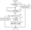
- FIG. 10 is a flowchart for explaining the detailed operation of the sequential illumination control process shown in FIG.
- each unit control device 10 selects the emergency exit number with the smallest count value (step 1001). Next, it is checked whether there is a next unit control device 10 adjacent to the next (step 1002). If there is no next unit control device 10 (NO in step 1002), this unit control device 10 is determined as the flow start unit control device corresponding to this emergency exit number (step 1004).
- step 1002 If it is determined in step 1002 that the next unit control device 10 is next adjacent (YES in step 1002), the emergency exit number-specific count value buffer unit 12 is referred to correspond to this emergency exit number. It is checked whether the count value in the next unit control device 10 is the minimum compared with the count values corresponding to other emergency exit numbers (step 1003). Here, if the count value in the next unit control device 10 is not minimum (NO in step 1003), this unit control device 10 is determined as the flow start unit control device corresponding to this emergency exit number (step 1004). ).
- step 1003 If it is determined in step 1003 that the count value in the next unit control device 10 corresponding to this emergency exit number is the minimum compared with the count values corresponding to other emergency exit numbers (YES in step 1003). Since this unit control device 10 is not a flow start unit control device, it checks whether an optical flow signal has been received from an adjacent unit control device 10 (step 1007). If the light flow signal is not received (NO in step 1007), the process returns to step 1007 to wait for the reception of the light flow signal, but if it is determined that the light flow signal is received (in step 1007).
- a plurality of light emitting elements 21-11 to 21-1n, 21-21 to 21-2n, 21-31 to 21- provided in the light emitting devices 20-1 to 20-8 corresponding to the unit control device 10 3n, 21-41 to 21-4n, 21-51 to 21-5n, 21-61 to 21-6n, 21-71 to 21-7n, 21-81 to 21-8n in order of decreasing count value Illuminance control is performed (step 1008). Then, this light flow signal is transferred to the adjacent unit control device 10 in the direction of decreasing the count value (step 1009).
- the unit control device 10 is configured to add “1” to its count value and transmit it to the next unit control device 10 in the count value setting process.
- the device 10 may be configured such that its own count value is transmitted as it is, and the addition of “1” is performed by the next unit control device 10.
- the number of light-emitting devices in each unit light-emitting device has been described as eight, but this number may be less than eight or more than eight.
- the number of light emitting elements in each light emitting device can be arbitrarily set.
- the number of each light-emitting device was made into the same number, respectively, you may set it so that it may each differ.
- the light-emitting element in the light-emitting device arranged in the passage that is not connected to the emergency exit and that has a dead end may be configured to be lit at, for example, 30% illuminance at the time of guidance. According to this configuration, it is possible to eliminate the inconvenience that the guided person gets lost in the passage by mistake.
- This invention can be used for evacuation guidance when an abnormality such as a fire occurs in a large-scale store, a hospital, an airport, or various exhibition halls.
- this invention has a plurality of light emitting devices arranged along a passage, and a control device that individually controls the illuminance of each of the plurality of light emitting devices, and the control device, when guiding, Comprising a guidance control means for sequentially controlling the illuminance of the light emitting device related to guiding of the plurality of light emitting devices to be different from the illuminance of the other adjacent light emitting devices to generate a flow of light in a desired guidance direction. Since it is comprised, the guidance system which can guide a to-be-guided person rapidly and without anxiety along a guidance path can be provided.
Landscapes
- Physics & Mathematics (AREA)
- General Physics & Mathematics (AREA)
- Circuit Arrangement For Electric Light Sources In General (AREA)
- Audible And Visible Signals (AREA)
- Alarm Systems (AREA)
- Fire Alarms (AREA)
Abstract
Description
11 非常口番号別カウント値記憶部
12 非常口番号別カウント値バッファ部
13 非常口番号設定部
14 光流れスタート単位制御装置設定部
15 照度制御部
16 異常検知センサ
17 制御部
20 単位発光装置
21-1~21-8 発光装置
Claims (10)
- 通路に沿って配列された複数の発光装置と、
前記複数の発光装置のそれぞれの照度を個別に制御する制御装置と、
を有し、
前記制御装置は、
誘導時に、前記複数の発光装置の誘導に係る発光装置の照度を隣接する他の発光装置の照度と異なるように順次制御して、所望の誘導方向に向かう光の流れを生じさせる誘導制御手段、
を具備することを特徴とする誘導システム。 - 前記制御装置は、
通常時は、前記複数の発光装置の照度を一定の照度に制御する通常時制御手段、
を具備し、
前記誘導制御手段は、
誘導時に、前記一定の照度を該一定の照度とは異なる他の照度に変化させ、該変化させた照度を基準として前記複数の発光装置の誘導に係る発光装置の照度を隣接する他の発光装置の照度と異なるように順次制御することを特徴とする請求項1に記載の誘導システム。 - 前記誘導制御手段は、
前記一定の照度を該一定の照度より低い他の照度に変化させ、該変化させた照度を基準として前記複数の発光装置の誘導に係る発光装置の照度を前記変化させた照度より高い照度に順次制御することを特徴とする請求項2に記載の誘導システム。 - 前記誘導制御手段は、
前記一定の照度を該一定の照度より高い他の照度に変化させ、該変化させた照度を基準として前記複数の発光装置の誘導に係る発光装置の照度を前記変化させた照度より低い照度に順次制御することを特徴とする請求項2に記載の誘導システム。 - 前記発光装置は、
前記通路の床面または側面にライン状に配置された複数の発光素子を有することを特徴とする請求項1乃至4のいずれか1項に記載の避難誘導システム。 - 前記複数の発光装置は、
所定数の発光装置からなる複数の単位発光装置、
を有し、
前記制御装置は、
前記単位発光装置にそれぞれ対応して設けられる複数の単位制御装置、
を有し、
前記単位制御装置は、
該単位制御装置の配置箇所における異常をそれぞれ検知する複数の異常検知センサと、
電源投入時に、非常口に向かう経路に沿った前記複数の単位制御装置のカウント値を該非常口の識別情報に対応して設定記憶するとともに、前記異常検知センサの異常検知時には、該異常検知センサによる異常発生箇所を避けた前記非常口に向かう経路に沿った前記複数の単位制御装置のカウント値を該非常口の識別情報に対応して設定記憶するカウント値設定手段と、
異常が発生していないときは、前記複数の単位発光装置の前記複数の発光装置を一定の照度で連続点灯制御し、異常発生時若しくは前記異常検知センサの異常検知時には、前記カウント値設定手段で設定記憶された前記単位制御装置のカウント値に基づき前記単位発光装置の前記複数の発光装置の誘導に係る各発光装置の照度を隣接する他の発光装置の照度と異なるように順次制御して、前記複数の発光装置により所望の誘導方向に向かう光の流れを生じさせる照度制御手段と、
を具備することを特徴とする請求項1乃至5のいずれか1項に記載の避難誘導システム。 - 前記非常口は、複数あり、
前記カウント値設定手段は、
各非常口からカウント信号を順次受信して非常口に向かう最短経路に沿った前記複数の単位制御装置のカウント値を各非常口の識別情報に対応して設定記憶することを特徴とする請求項6に記載の避難誘導システム。 - 前記照度制御手段は、
前記異常発生時若しくは前記異常検知センサの異常検知時に、隣接する単位制御装置に記憶された非常口情報及びカウント値に基づき光流れスタート単位制御装置を決定し、該決定した光流れスタート単位制御装置から所定周期で光流れ信号を送信し、該光流れ信号を受信した各単位制御装置は、前記カウント値に基づき該光流れ信号を次の単位制御装置に順次送信することにより前記光の流れを生じさせることを特徴とする請求項6または7に記載の避難誘導システム。 - 前記単位制御装置は、
隣接する単位制御装置に設定記憶された非常口情報及びカウント値を記憶するバッファ手段を有し、
前記照度制御手段は、
前記カウント値が最小の非常口に対応する非常口情報を選択し、該選択した非常口情報が示す非常口から離れる方向に対応する単位制御装置のカウント値が最小でなくなると前記バッファ手段の記憶情報を参照して判別すると、該判別した照度制御手段を有する単位制御装置を前記光流れスタート単位制御装置として決定することを特徴とする請求項6乃至8のいずれか1項に記載の避難誘導システム。 - 前記照度制御手段は、
前記選択した非常口情報に対応する非常口から離れる方向に前記単位制御装置がないと前記バッファ手段の記憶情報を参照して判別すると、該判別した照度制御手段を有する単位制御装置を前記光流れスタート単位制御装置として決定することを特徴とする請求項9に記載の避難誘導システム。
Priority Applications (4)
| Application Number | Priority Date | Filing Date | Title |
|---|---|---|---|
| CA2915003A CA2915003A1 (en) | 2013-12-11 | 2014-11-27 | Guidance system |
| US14/896,266 US9747764B2 (en) | 2013-12-11 | 2014-11-27 | Guidance system |
| EP14869331.0A EP3082116A4 (en) | 2013-12-11 | 2014-11-27 | Guidance system |
| AU2014362636A AU2014362636A1 (en) | 2013-12-11 | 2014-11-27 | Guidance system |
Applications Claiming Priority (2)
| Application Number | Priority Date | Filing Date | Title |
|---|---|---|---|
| JP2013-256217 | 2013-12-11 | ||
| JP2013256217A JP5781144B2 (ja) | 2013-12-11 | 2013-12-11 | 誘導システム |
Publications (1)
| Publication Number | Publication Date |
|---|---|
| WO2015087706A1 true WO2015087706A1 (ja) | 2015-06-18 |
Family
ID=53371018
Family Applications (1)
| Application Number | Title | Priority Date | Filing Date |
|---|---|---|---|
| PCT/JP2014/081355 Ceased WO2015087706A1 (ja) | 2013-12-11 | 2014-11-27 | 誘導システム |
Country Status (6)
| Country | Link |
|---|---|
| US (1) | US9747764B2 (ja) |
| EP (1) | EP3082116A4 (ja) |
| JP (1) | JP5781144B2 (ja) |
| AU (1) | AU2014362636A1 (ja) |
| CA (1) | CA2915003A1 (ja) |
| WO (1) | WO2015087706A1 (ja) |
Families Citing this family (7)
| Publication number | Priority date | Publication date | Assignee | Title |
|---|---|---|---|---|
| DE102016207705A1 (de) * | 2016-05-04 | 2017-11-09 | Robert Bosch Gmbh | Rauchdetektionsvorrichtung, Verfahren zur Detektion von Rauch eines Brandes sowie Computerprogramm |
| US11037416B2 (en) | 2018-07-20 | 2021-06-15 | Comcast Cable Communications, Llc | Methods and systems for path lighting |
| CN109714873B (zh) * | 2018-12-18 | 2020-04-24 | 中川电气科技有限公司 | 一种自动规划最短疏散逃生路径的应急照明控制器及方法 |
| CN110660222B (zh) * | 2019-11-01 | 2024-05-10 | 河北工业大学 | 一种智能环保道路黑烟车辆电子抓拍系统 |
| US11176788B2 (en) * | 2019-12-12 | 2021-11-16 | Johnson Controls Fire Protection LP | Emergency notification system and method |
| AU2021200002A1 (en) * | 2020-01-05 | 2021-07-22 | Mitchell Lee Lewis | Safety corridor arrangement |
| US10991216B1 (en) | 2020-12-04 | 2021-04-27 | Khaled Alali | Auditory and visual guidance system for emergency evacuation |
Citations (4)
| Publication number | Priority date | Publication date | Assignee | Title |
|---|---|---|---|---|
| JPS547898A (en) * | 1977-06-21 | 1979-01-20 | Nohmi Bosai Kogyo Co Ltd | Escape guide device |
| JPH04137097A (ja) * | 1990-09-28 | 1992-05-12 | Toshiba Lighting & Technol Corp | 避難誘導装置 |
| JPH05135286A (ja) | 1991-11-13 | 1993-06-01 | Fujitsu Ltd | 避難誘導システム |
| WO2009017628A2 (en) * | 2007-07-26 | 2009-02-05 | Zarian James R | Programmable, progressive guiding system: apparatus and method |
Family Cites Families (13)
| Publication number | Priority date | Publication date | Assignee | Title |
|---|---|---|---|---|
| US4347499A (en) * | 1981-01-02 | 1982-08-31 | Thomas F. Burkman, Sr. | Emergency guidance system |
| EP0882576B1 (en) | 1996-10-03 | 2004-04-14 | Teijin Limited | Release film |
| US6150943A (en) * | 1999-07-14 | 2000-11-21 | American Xtal Technology, Inc. | Laser director for fire evacuation path |
| DE10246033B4 (de) * | 2002-10-02 | 2006-02-23 | Novar Gmbh | Fluchtleitsystem |
| US20070103329A1 (en) * | 2005-11-09 | 2007-05-10 | Lin Ming H | Direction indicating device |
| JP2009017628A (ja) | 2007-07-02 | 2009-01-22 | Fuji Electric Systems Co Ltd | 配電盤のシャッタ装置 |
| US20090066522A1 (en) * | 2007-09-11 | 2009-03-12 | Il- Won Tech Co., Ltd | Emergency guidance lamp system for guiding to nearest exit in the event of fire |
| FI122351B (fi) * | 2008-06-19 | 2011-12-15 | Marimils Oy | Menetelmä, järjestelmä ja laite ohjaamiseksi, opastamiseksi ja varoittamiseksi |
| GB0820606D0 (en) * | 2008-11-11 | 2008-12-17 | Patterson Kieran | Route guidance and evacuation system |
| US8228176B2 (en) * | 2009-03-31 | 2012-07-24 | Timothy John Lewis | Electronic guides, incident response methods, incident response systems, and incident monitoring methods |
| EP2462783B1 (en) * | 2009-08-05 | 2013-04-17 | Koninklijke Philips Electronics N.V. | Light guiding system and a method for controlling the same |
| RU2617333C2 (ru) * | 2011-07-01 | 2017-04-24 | Филипс Лайтинг Холдинг Б.В. | Способ вывода человека в опорное место и световая система, содержащая множество источников света, для использования в таком способе |
| EP2881286B1 (en) * | 2012-08-06 | 2018-05-23 | Shindengen Electric Manufacturing Co., Ltd. | Direction-indication device |
-
2013
- 2013-12-11 JP JP2013256217A patent/JP5781144B2/ja not_active Expired - Fee Related
-
2014
- 2014-11-27 CA CA2915003A patent/CA2915003A1/en not_active Abandoned
- 2014-11-27 AU AU2014362636A patent/AU2014362636A1/en not_active Abandoned
- 2014-11-27 EP EP14869331.0A patent/EP3082116A4/en not_active Withdrawn
- 2014-11-27 WO PCT/JP2014/081355 patent/WO2015087706A1/ja not_active Ceased
- 2014-11-27 US US14/896,266 patent/US9747764B2/en not_active Expired - Fee Related
Patent Citations (4)
| Publication number | Priority date | Publication date | Assignee | Title |
|---|---|---|---|---|
| JPS547898A (en) * | 1977-06-21 | 1979-01-20 | Nohmi Bosai Kogyo Co Ltd | Escape guide device |
| JPH04137097A (ja) * | 1990-09-28 | 1992-05-12 | Toshiba Lighting & Technol Corp | 避難誘導装置 |
| JPH05135286A (ja) | 1991-11-13 | 1993-06-01 | Fujitsu Ltd | 避難誘導システム |
| WO2009017628A2 (en) * | 2007-07-26 | 2009-02-05 | Zarian James R | Programmable, progressive guiding system: apparatus and method |
Non-Patent Citations (1)
| Title |
|---|
| See also references of EP3082116A4 * |
Also Published As
| Publication number | Publication date |
|---|---|
| AU2014362636A1 (en) | 2016-01-21 |
| EP3082116A1 (en) | 2016-10-19 |
| EP3082116A4 (en) | 2017-08-02 |
| US9747764B2 (en) | 2017-08-29 |
| JP5781144B2 (ja) | 2015-09-16 |
| US20160275761A1 (en) | 2016-09-22 |
| CA2915003A1 (en) | 2015-06-18 |
| JP2015114829A (ja) | 2015-06-22 |
Similar Documents
| Publication | Publication Date | Title |
|---|---|---|
| WO2015087706A1 (ja) | 誘導システム | |
| JP7151835B2 (ja) | 情報処理装置、情報処理方法およびプログラム | |
| JP5902995B2 (ja) | Ledチューブを用いた移動システム、移動方法及びledチューブ | |
| CN103620656B (zh) | 用于将人引导至参考地点的方法和用在这种方法中的包括多个光源的照明系统 | |
| WO2012102219A1 (ja) | 照明装置および照明システム | |
| KR20200074627A (ko) | 바닥 매립형 led 피난 유도 장치 | |
| JP2015084188A (ja) | 避難誘導システム | |
| JP2011154706A (ja) | 避難誘導システムおよび誘導装置 | |
| JP4873723B2 (ja) | 避難誘導システムおよび誘導装置および視覚障害者案内装置 | |
| KR101618605B1 (ko) | 비상구 위치로 유도하는 효과를 극대화하기 위한 사운드 기반의 비상유도장치 | |
| JP2015135702A (ja) | 誘導システム | |
| WO2012073525A1 (ja) | 誘導経路表示システム | |
| KR200206904Y1 (ko) | 비상구등의 방향지시 유도장치 | |
| JP6169665B2 (ja) | 避難誘導システム | |
| JP6396750B2 (ja) | 火災感知器又は火災警報器 | |
| KR20170010346A (ko) | 대피안내 겸용 조명장치 | |
| JP4995607B2 (ja) | 熱線式ワイヤレス発信器 | |
| JP4631194B2 (ja) | 避難誘導システム | |
| JP5850578B2 (ja) | 避難誘導システム | |
| CN103024976A (zh) | 感测单元、带感测单元的发光装置、led驱动器、照明系统 | |
| JP5788204B2 (ja) | 照明装置および照明システム | |
| KR20180005165A (ko) | 역 또는 임의의 다른 공공장소 내의 주변환경을 동적으로 운영하기 위한 시스템 | |
| KR20220147979A (ko) | 피난경로 출력시스템 | |
| JP5490213B2 (ja) | 演出装置 | |
| JP5719616B2 (ja) | 照明装置 |
Legal Events
| Date | Code | Title | Description |
|---|---|---|---|
| 121 | Ep: the epo has been informed by wipo that ep was designated in this application |
Ref document number: 14869331 Country of ref document: EP Kind code of ref document: A1 |
|
| WWE | Wipo information: entry into national phase |
Ref document number: 14896266 Country of ref document: US |
|
| ENP | Entry into the national phase |
Ref document number: 2915003 Country of ref document: CA |
|
| ENP | Entry into the national phase |
Ref document number: 2014362636 Country of ref document: AU Date of ref document: 20141127 Kind code of ref document: A |
|
| NENP | Non-entry into the national phase |
Ref country code: DE |
|
| REEP | Request for entry into the european phase |
Ref document number: 2014869331 Country of ref document: EP |
|
| WWE | Wipo information: entry into national phase |
Ref document number: 2014869331 Country of ref document: EP |