WO2015097952A1 - Batterie, électrolyte, bloc-batterie, dispositif électronique, véhicule électrique, dispositif d'accumulation d'électricité, et système électrique - Google Patents
Batterie, électrolyte, bloc-batterie, dispositif électronique, véhicule électrique, dispositif d'accumulation d'électricité, et système électrique Download PDFInfo
- Publication number
- WO2015097952A1 WO2015097952A1 PCT/JP2014/005256 JP2014005256W WO2015097952A1 WO 2015097952 A1 WO2015097952 A1 WO 2015097952A1 JP 2014005256 W JP2014005256 W JP 2014005256W WO 2015097952 A1 WO2015097952 A1 WO 2015097952A1
- Authority
- WO
- WIPO (PCT)
- Prior art keywords
- battery
- particles
- electrolyte
- particle
- gel electrolyte
- Prior art date
- Legal status (The legal status is an assumption and is not a legal conclusion. Google has not performed a legal analysis and makes no representation as to the accuracy of the status listed.)
- Ceased
Links
Images




Classifications
-
- H—ELECTRICITY
- H01—ELECTRIC ELEMENTS
- H01M—PROCESSES OR MEANS, e.g. BATTERIES, FOR THE DIRECT CONVERSION OF CHEMICAL ENERGY INTO ELECTRICAL ENERGY
- H01M10/00—Secondary cells; Manufacture thereof
- H01M10/05—Accumulators with non-aqueous electrolyte
- H01M10/056—Accumulators with non-aqueous electrolyte characterised by the materials used as electrolytes, e.g. mixed inorganic/organic electrolytes
-
- B—PERFORMING OPERATIONS; TRANSPORTING
- B60—VEHICLES IN GENERAL
- B60L—PROPULSION OF ELECTRICALLY-PROPELLED VEHICLES; SUPPLYING ELECTRIC POWER FOR AUXILIARY EQUIPMENT OF ELECTRICALLY-PROPELLED VEHICLES; ELECTRODYNAMIC BRAKE SYSTEMS FOR VEHICLES IN GENERAL; MAGNETIC SUSPENSION OR LEVITATION FOR VEHICLES; MONITORING OPERATING VARIABLES OF ELECTRICALLY-PROPELLED VEHICLES; ELECTRIC SAFETY DEVICES FOR ELECTRICALLY-PROPELLED VEHICLES
- B60L53/00—Methods of charging batteries, specially adapted for electric vehicles; Charging stations or on-board charging equipment therefor; Exchange of energy storage elements in electric vehicles
- B60L53/20—Methods of charging batteries, specially adapted for electric vehicles; Charging stations or on-board charging equipment therefor; Exchange of energy storage elements in electric vehicles characterised by converters located in the vehicle
-
- B—PERFORMING OPERATIONS; TRANSPORTING
- B60—VEHICLES IN GENERAL
- B60L—PROPULSION OF ELECTRICALLY-PROPELLED VEHICLES; SUPPLYING ELECTRIC POWER FOR AUXILIARY EQUIPMENT OF ELECTRICALLY-PROPELLED VEHICLES; ELECTRODYNAMIC BRAKE SYSTEMS FOR VEHICLES IN GENERAL; MAGNETIC SUSPENSION OR LEVITATION FOR VEHICLES; MONITORING OPERATING VARIABLES OF ELECTRICALLY-PROPELLED VEHICLES; ELECTRIC SAFETY DEVICES FOR ELECTRICALLY-PROPELLED VEHICLES
- B60L58/00—Methods or circuit arrangements for monitoring or controlling batteries or fuel cells, specially adapted for electric vehicles
- B60L58/10—Methods or circuit arrangements for monitoring or controlling batteries or fuel cells, specially adapted for electric vehicles for monitoring or controlling batteries
- B60L58/12—Methods or circuit arrangements for monitoring or controlling batteries or fuel cells, specially adapted for electric vehicles for monitoring or controlling batteries responding to state of charge [SoC]
- B60L58/15—Preventing overcharging
-
- H—ELECTRICITY
- H01—ELECTRIC ELEMENTS
- H01M—PROCESSES OR MEANS, e.g. BATTERIES, FOR THE DIRECT CONVERSION OF CHEMICAL ENERGY INTO ELECTRICAL ENERGY
- H01M10/00—Secondary cells; Manufacture thereof
- H01M10/05—Accumulators with non-aqueous electrolyte
- H01M10/052—Li-accumulators
-
- H—ELECTRICITY
- H01—ELECTRIC ELEMENTS
- H01M—PROCESSES OR MEANS, e.g. BATTERIES, FOR THE DIRECT CONVERSION OF CHEMICAL ENERGY INTO ELECTRICAL ENERGY
- H01M10/00—Secondary cells; Manufacture thereof
- H01M10/05—Accumulators with non-aqueous electrolyte
- H01M10/056—Accumulators with non-aqueous electrolyte characterised by the materials used as electrolytes, e.g. mixed inorganic/organic electrolytes
- H01M10/0564—Accumulators with non-aqueous electrolyte characterised by the materials used as electrolytes, e.g. mixed inorganic/organic electrolytes the electrolyte being constituted of organic materials only
- H01M10/0565—Polymeric materials, e.g. gel-type or solid-type
-
- H—ELECTRICITY
- H01—ELECTRIC ELEMENTS
- H01M—PROCESSES OR MEANS, e.g. BATTERIES, FOR THE DIRECT CONVERSION OF CHEMICAL ENERGY INTO ELECTRICAL ENERGY
- H01M10/00—Secondary cells; Manufacture thereof
- H01M10/05—Accumulators with non-aqueous electrolyte
- H01M10/058—Construction or manufacture
- H01M10/0585—Construction or manufacture of accumulators having only flat construction elements, i.e. flat positive electrodes, flat negative electrodes and flat separators
-
- H—ELECTRICITY
- H01—ELECTRIC ELEMENTS
- H01M—PROCESSES OR MEANS, e.g. BATTERIES, FOR THE DIRECT CONVERSION OF CHEMICAL ENERGY INTO ELECTRICAL ENERGY
- H01M10/00—Secondary cells; Manufacture thereof
- H01M10/05—Accumulators with non-aqueous electrolyte
- H01M10/058—Construction or manufacture
- H01M10/0587—Construction or manufacture of accumulators having only wound construction elements, i.e. wound positive electrodes, wound negative electrodes and wound separators
-
- H—ELECTRICITY
- H01—ELECTRIC ELEMENTS
- H01M—PROCESSES OR MEANS, e.g. BATTERIES, FOR THE DIRECT CONVERSION OF CHEMICAL ENERGY INTO ELECTRICAL ENERGY
- H01M10/00—Secondary cells; Manufacture thereof
- H01M10/42—Methods or arrangements for servicing or maintenance of secondary cells or secondary half-cells
- H01M10/425—Structural combination with electronic components, e.g. electronic circuits integrated to the outside of the casing
- H01M10/4257—Smart batteries, e.g. electronic circuits inside the housing of the cells or batteries
-
- H—ELECTRICITY
- H01—ELECTRIC ELEMENTS
- H01M—PROCESSES OR MEANS, e.g. BATTERIES, FOR THE DIRECT CONVERSION OF CHEMICAL ENERGY INTO ELECTRICAL ENERGY
- H01M10/00—Secondary cells; Manufacture thereof
- H01M10/42—Methods or arrangements for servicing or maintenance of secondary cells or secondary half-cells
- H01M10/46—Accumulators structurally combined with charging apparatus
-
- H—ELECTRICITY
- H01—ELECTRIC ELEMENTS
- H01M—PROCESSES OR MEANS, e.g. BATTERIES, FOR THE DIRECT CONVERSION OF CHEMICAL ENERGY INTO ELECTRICAL ENERGY
- H01M10/00—Secondary cells; Manufacture thereof
- H01M10/42—Methods or arrangements for servicing or maintenance of secondary cells or secondary half-cells
- H01M10/48—Accumulators combined with arrangements for measuring, testing or indicating the condition of cells, e.g. the level or density of the electrolyte
-
- H—ELECTRICITY
- H01—ELECTRIC ELEMENTS
- H01M—PROCESSES OR MEANS, e.g. BATTERIES, FOR THE DIRECT CONVERSION OF CHEMICAL ENERGY INTO ELECTRICAL ENERGY
- H01M10/00—Secondary cells; Manufacture thereof
- H01M10/42—Methods or arrangements for servicing or maintenance of secondary cells or secondary half-cells
- H01M10/48—Accumulators combined with arrangements for measuring, testing or indicating the condition of cells, e.g. the level or density of the electrolyte
- H01M10/482—Accumulators combined with arrangements for measuring, testing or indicating the condition of cells, e.g. the level or density of the electrolyte for several batteries or cells simultaneously or sequentially
-
- H—ELECTRICITY
- H01—ELECTRIC ELEMENTS
- H01M—PROCESSES OR MEANS, e.g. BATTERIES, FOR THE DIRECT CONVERSION OF CHEMICAL ENERGY INTO ELECTRICAL ENERGY
- H01M10/00—Secondary cells; Manufacture thereof
- H01M10/42—Methods or arrangements for servicing or maintenance of secondary cells or secondary half-cells
- H01M10/48—Accumulators combined with arrangements for measuring, testing or indicating the condition of cells, e.g. the level or density of the electrolyte
- H01M10/486—Accumulators combined with arrangements for measuring, testing or indicating the condition of cells, e.g. the level or density of the electrolyte for measuring temperature
-
- H—ELECTRICITY
- H01—ELECTRIC ELEMENTS
- H01M—PROCESSES OR MEANS, e.g. BATTERIES, FOR THE DIRECT CONVERSION OF CHEMICAL ENERGY INTO ELECTRICAL ENERGY
- H01M4/00—Electrodes
- H01M4/02—Electrodes composed of, or comprising, active material
- H01M4/13—Electrodes for accumulators with non-aqueous electrolyte, e.g. for lithium-accumulators; Processes of manufacture thereof
-
- H—ELECTRICITY
- H01—ELECTRIC ELEMENTS
- H01M—PROCESSES OR MEANS, e.g. BATTERIES, FOR THE DIRECT CONVERSION OF CHEMICAL ENERGY INTO ELECTRICAL ENERGY
- H01M4/00—Electrodes
- H01M4/02—Electrodes composed of, or comprising, active material
- H01M4/13—Electrodes for accumulators with non-aqueous electrolyte, e.g. for lithium-accumulators; Processes of manufacture thereof
- H01M4/131—Electrodes based on mixed oxides or hydroxides, or on mixtures of oxides or hydroxides, e.g. LiCoOx
-
- H—ELECTRICITY
- H01—ELECTRIC ELEMENTS
- H01M—PROCESSES OR MEANS, e.g. BATTERIES, FOR THE DIRECT CONVERSION OF CHEMICAL ENERGY INTO ELECTRICAL ENERGY
- H01M4/00—Electrodes
- H01M4/02—Electrodes composed of, or comprising, active material
- H01M4/13—Electrodes for accumulators with non-aqueous electrolyte, e.g. for lithium-accumulators; Processes of manufacture thereof
- H01M4/133—Electrodes based on carbonaceous material, e.g. graphite-intercalation compounds or CFx
-
- H—ELECTRICITY
- H01—ELECTRIC ELEMENTS
- H01M—PROCESSES OR MEANS, e.g. BATTERIES, FOR THE DIRECT CONVERSION OF CHEMICAL ENERGY INTO ELECTRICAL ENERGY
- H01M4/00—Electrodes
- H01M4/02—Electrodes composed of, or comprising, active material
- H01M4/36—Selection of substances as active materials, active masses, active liquids
- H01M4/48—Selection of substances as active materials, active masses, active liquids of inorganic oxides or hydroxides
- H01M4/52—Selection of substances as active materials, active masses, active liquids of inorganic oxides or hydroxides of nickel, cobalt or iron
- H01M4/525—Selection of substances as active materials, active masses, active liquids of inorganic oxides or hydroxides of nickel, cobalt or iron of mixed oxides or hydroxides containing iron, cobalt or nickel for inserting or intercalating light metals, e.g. LiNiO2, LiCoO2 or LiCoOxFy
-
- H—ELECTRICITY
- H01—ELECTRIC ELEMENTS
- H01M—PROCESSES OR MEANS, e.g. BATTERIES, FOR THE DIRECT CONVERSION OF CHEMICAL ENERGY INTO ELECTRICAL ENERGY
- H01M4/00—Electrodes
- H01M4/02—Electrodes composed of, or comprising, active material
- H01M4/36—Selection of substances as active materials, active masses, active liquids
- H01M4/58—Selection of substances as active materials, active masses, active liquids of inorganic compounds other than oxides or hydroxides, e.g. sulfides, selenides, tellurides, halogenides or LiCoFy; of polyanionic structures, e.g. phosphates, silicates or borates
- H01M4/583—Carbonaceous material, e.g. graphite-intercalation compounds or CFx
- H01M4/587—Carbonaceous material, e.g. graphite-intercalation compounds or CFx for inserting or intercalating light metals
-
- H—ELECTRICITY
- H01—ELECTRIC ELEMENTS
- H01M—PROCESSES OR MEANS, e.g. BATTERIES, FOR THE DIRECT CONVERSION OF CHEMICAL ENERGY INTO ELECTRICAL ENERGY
- H01M4/00—Electrodes
- H01M4/02—Electrodes composed of, or comprising, active material
- H01M4/62—Selection of inactive substances as ingredients for active masses, e.g. binders, fillers
- H01M4/621—Binders
- H01M4/622—Binders being polymers
-
- H—ELECTRICITY
- H01—ELECTRIC ELEMENTS
- H01M—PROCESSES OR MEANS, e.g. BATTERIES, FOR THE DIRECT CONVERSION OF CHEMICAL ENERGY INTO ELECTRICAL ENERGY
- H01M4/00—Electrodes
- H01M4/02—Electrodes composed of, or comprising, active material
- H01M4/62—Selection of inactive substances as ingredients for active masses, e.g. binders, fillers
- H01M4/621—Binders
- H01M4/622—Binders being polymers
- H01M4/623—Binders being polymers fluorinated polymers
-
- H—ELECTRICITY
- H01—ELECTRIC ELEMENTS
- H01M—PROCESSES OR MEANS, e.g. BATTERIES, FOR THE DIRECT CONVERSION OF CHEMICAL ENERGY INTO ELECTRICAL ENERGY
- H01M4/00—Electrodes
- H01M4/02—Electrodes composed of, or comprising, active material
- H01M4/62—Selection of inactive substances as ingredients for active masses, e.g. binders, fillers
- H01M4/624—Electric conductive fillers
- H01M4/625—Carbon or graphite
-
- H—ELECTRICITY
- H01—ELECTRIC ELEMENTS
- H01M—PROCESSES OR MEANS, e.g. BATTERIES, FOR THE DIRECT CONVERSION OF CHEMICAL ENERGY INTO ELECTRICAL ENERGY
- H01M4/00—Electrodes
- H01M4/02—Electrodes composed of, or comprising, active material
- H01M4/64—Carriers or collectors
- H01M4/66—Selection of materials
- H01M4/661—Metal or alloys, e.g. alloy coatings
-
- H—ELECTRICITY
- H01—ELECTRIC ELEMENTS
- H01M—PROCESSES OR MEANS, e.g. BATTERIES, FOR THE DIRECT CONVERSION OF CHEMICAL ENERGY INTO ELECTRICAL ENERGY
- H01M4/00—Electrodes
- H01M4/02—Electrodes composed of, or comprising, active material
- H01M2004/026—Electrodes composed of, or comprising, active material characterised by the polarity
- H01M2004/027—Negative electrodes
-
- H—ELECTRICITY
- H01—ELECTRIC ELEMENTS
- H01M—PROCESSES OR MEANS, e.g. BATTERIES, FOR THE DIRECT CONVERSION OF CHEMICAL ENERGY INTO ELECTRICAL ENERGY
- H01M4/00—Electrodes
- H01M4/02—Electrodes composed of, or comprising, active material
- H01M2004/026—Electrodes composed of, or comprising, active material characterised by the polarity
- H01M2004/028—Positive electrodes
-
- H—ELECTRICITY
- H01—ELECTRIC ELEMENTS
- H01M—PROCESSES OR MEANS, e.g. BATTERIES, FOR THE DIRECT CONVERSION OF CHEMICAL ENERGY INTO ELECTRICAL ENERGY
- H01M10/00—Secondary cells; Manufacture thereof
- H01M10/42—Methods or arrangements for servicing or maintenance of secondary cells or secondary half-cells
- H01M10/425—Structural combination with electronic components, e.g. electronic circuits integrated to the outside of the casing
- H01M2010/4271—Battery management systems including electronic circuits, e.g. control of current or voltage to keep battery in healthy state, cell balancing
-
- H—ELECTRICITY
- H01—ELECTRIC ELEMENTS
- H01M—PROCESSES OR MEANS, e.g. BATTERIES, FOR THE DIRECT CONVERSION OF CHEMICAL ENERGY INTO ELECTRICAL ENERGY
- H01M10/00—Secondary cells; Manufacture thereof
- H01M10/42—Methods or arrangements for servicing or maintenance of secondary cells or secondary half-cells
- H01M10/425—Structural combination with electronic components, e.g. electronic circuits integrated to the outside of the casing
- H01M2010/4278—Systems for data transfer from batteries, e.g. transfer of battery parameters to a controller, data transferred between battery controller and main controller
-
- H—ELECTRICITY
- H01—ELECTRIC ELEMENTS
- H01M—PROCESSES OR MEANS, e.g. BATTERIES, FOR THE DIRECT CONVERSION OF CHEMICAL ENERGY INTO ELECTRICAL ENERGY
- H01M2220/00—Batteries for particular applications
- H01M2220/20—Batteries in motive systems, e.g. vehicle, ship, plane
-
- H—ELECTRICITY
- H01—ELECTRIC ELEMENTS
- H01M—PROCESSES OR MEANS, e.g. BATTERIES, FOR THE DIRECT CONVERSION OF CHEMICAL ENERGY INTO ELECTRICAL ENERGY
- H01M2220/00—Batteries for particular applications
- H01M2220/30—Batteries in portable systems, e.g. mobile phone, laptop
-
- H—ELECTRICITY
- H01—ELECTRIC ELEMENTS
- H01M—PROCESSES OR MEANS, e.g. BATTERIES, FOR THE DIRECT CONVERSION OF CHEMICAL ENERGY INTO ELECTRICAL ENERGY
- H01M2300/00—Electrolytes
- H01M2300/0017—Non-aqueous electrolytes
- H01M2300/0025—Organic electrolyte
- H01M2300/0028—Organic electrolyte characterised by the solvent
- H01M2300/0037—Mixture of solvents
- H01M2300/004—Three solvents
-
- H—ELECTRICITY
- H01—ELECTRIC ELEMENTS
- H01M—PROCESSES OR MEANS, e.g. BATTERIES, FOR THE DIRECT CONVERSION OF CHEMICAL ENERGY INTO ELECTRICAL ENERGY
- H01M2300/00—Electrolytes
- H01M2300/0085—Immobilising or gelification of electrolyte
-
- H—ELECTRICITY
- H01—ELECTRIC ELEMENTS
- H01M—PROCESSES OR MEANS, e.g. BATTERIES, FOR THE DIRECT CONVERSION OF CHEMICAL ENERGY INTO ELECTRICAL ENERGY
- H01M2300/00—Electrolytes
- H01M2300/0088—Composites
- H01M2300/0091—Composites in the form of mixtures
-
- H—ELECTRICITY
- H01—ELECTRIC ELEMENTS
- H01M—PROCESSES OR MEANS, e.g. BATTERIES, FOR THE DIRECT CONVERSION OF CHEMICAL ENERGY INTO ELECTRICAL ENERGY
- H01M4/00—Electrodes
- H01M4/02—Electrodes composed of, or comprising, active material
- H01M4/04—Processes of manufacture in general
- H01M4/0402—Methods of deposition of the material
- H01M4/0404—Methods of deposition of the material by coating on electrode collectors
-
- H—ELECTRICITY
- H01—ELECTRIC ELEMENTS
- H01M—PROCESSES OR MEANS, e.g. BATTERIES, FOR THE DIRECT CONVERSION OF CHEMICAL ENERGY INTO ELECTRICAL ENERGY
- H01M4/00—Electrodes
- H01M4/02—Electrodes composed of, or comprising, active material
- H01M4/13—Electrodes for accumulators with non-aqueous electrolyte, e.g. for lithium-accumulators; Processes of manufacture thereof
- H01M4/139—Processes of manufacture
- H01M4/1391—Processes of manufacture of electrodes based on mixed oxides or hydroxides, or on mixtures of oxides or hydroxides, e.g. LiCoOx
-
- H—ELECTRICITY
- H01—ELECTRIC ELEMENTS
- H01M—PROCESSES OR MEANS, e.g. BATTERIES, FOR THE DIRECT CONVERSION OF CHEMICAL ENERGY INTO ELECTRICAL ENERGY
- H01M4/00—Electrodes
- H01M4/02—Electrodes composed of, or comprising, active material
- H01M4/13—Electrodes for accumulators with non-aqueous electrolyte, e.g. for lithium-accumulators; Processes of manufacture thereof
- H01M4/139—Processes of manufacture
- H01M4/1393—Processes of manufacture of electrodes based on carbonaceous material, e.g. graphite-intercalation compounds or CFx
-
- H—ELECTRICITY
- H01—ELECTRIC ELEMENTS
- H01M—PROCESSES OR MEANS, e.g. BATTERIES, FOR THE DIRECT CONVERSION OF CHEMICAL ENERGY INTO ELECTRICAL ENERGY
- H01M50/00—Constructional details or processes of manufacture of the non-active parts of electrochemical cells other than fuel cells, e.g. hybrid cells
- H01M50/10—Primary casings; Jackets or wrappings
- H01M50/102—Primary casings; Jackets or wrappings characterised by their shape or physical structure
- H01M50/105—Pouches or flexible bags
-
- H—ELECTRICITY
- H01—ELECTRIC ELEMENTS
- H01M—PROCESSES OR MEANS, e.g. BATTERIES, FOR THE DIRECT CONVERSION OF CHEMICAL ENERGY INTO ELECTRICAL ENERGY
- H01M50/00—Constructional details or processes of manufacture of the non-active parts of electrochemical cells other than fuel cells, e.g. hybrid cells
- H01M50/10—Primary casings; Jackets or wrappings
- H01M50/172—Arrangements of electric connectors penetrating the casing
- H01M50/174—Arrangements of electric connectors penetrating the casing adapted for the shape of the cells
- H01M50/178—Arrangements of electric connectors penetrating the casing adapted for the shape of the cells for pouch or flexible bag cells
-
- H—ELECTRICITY
- H01—ELECTRIC ELEMENTS
- H01M—PROCESSES OR MEANS, e.g. BATTERIES, FOR THE DIRECT CONVERSION OF CHEMICAL ENERGY INTO ELECTRICAL ENERGY
- H01M50/00—Constructional details or processes of manufacture of the non-active parts of electrochemical cells other than fuel cells, e.g. hybrid cells
- H01M50/50—Current conducting connections for cells or batteries
- H01M50/543—Terminals
- H01M50/547—Terminals characterised by the disposition of the terminals on the cells
- H01M50/55—Terminals characterised by the disposition of the terminals on the cells on the same side of the cell
-
- H—ELECTRICITY
- H01—ELECTRIC ELEMENTS
- H01M—PROCESSES OR MEANS, e.g. BATTERIES, FOR THE DIRECT CONVERSION OF CHEMICAL ENERGY INTO ELECTRICAL ENERGY
- H01M50/00—Constructional details or processes of manufacture of the non-active parts of electrochemical cells other than fuel cells, e.g. hybrid cells
- H01M50/50—Current conducting connections for cells or batteries
- H01M50/543—Terminals
- H01M50/552—Terminals characterised by their shape
- H01M50/553—Terminals adapted for prismatic, pouch or rectangular cells
-
- Y—GENERAL TAGGING OF NEW TECHNOLOGICAL DEVELOPMENTS; GENERAL TAGGING OF CROSS-SECTIONAL TECHNOLOGIES SPANNING OVER SEVERAL SECTIONS OF THE IPC; TECHNICAL SUBJECTS COVERED BY FORMER USPC CROSS-REFERENCE ART COLLECTIONS [XRACs] AND DIGESTS
- Y02—TECHNOLOGIES OR APPLICATIONS FOR MITIGATION OR ADAPTATION AGAINST CLIMATE CHANGE
- Y02E—REDUCTION OF GREENHOUSE GAS [GHG] EMISSIONS, RELATED TO ENERGY GENERATION, TRANSMISSION OR DISTRIBUTION
- Y02E60/00—Enabling technologies; Technologies with a potential or indirect contribution to GHG emissions mitigation
- Y02E60/10—Energy storage using batteries
-
- Y—GENERAL TAGGING OF NEW TECHNOLOGICAL DEVELOPMENTS; GENERAL TAGGING OF CROSS-SECTIONAL TECHNOLOGIES SPANNING OVER SEVERAL SECTIONS OF THE IPC; TECHNICAL SUBJECTS COVERED BY FORMER USPC CROSS-REFERENCE ART COLLECTIONS [XRACs] AND DIGESTS
- Y02—TECHNOLOGIES OR APPLICATIONS FOR MITIGATION OR ADAPTATION AGAINST CLIMATE CHANGE
- Y02P—CLIMATE CHANGE MITIGATION TECHNOLOGIES IN THE PRODUCTION OR PROCESSING OF GOODS
- Y02P70/00—Climate change mitigation technologies in the production process for final industrial or consumer products
- Y02P70/50—Manufacturing or production processes characterised by the final manufactured product
-
- Y—GENERAL TAGGING OF NEW TECHNOLOGICAL DEVELOPMENTS; GENERAL TAGGING OF CROSS-SECTIONAL TECHNOLOGIES SPANNING OVER SEVERAL SECTIONS OF THE IPC; TECHNICAL SUBJECTS COVERED BY FORMER USPC CROSS-REFERENCE ART COLLECTIONS [XRACs] AND DIGESTS
- Y02—TECHNOLOGIES OR APPLICATIONS FOR MITIGATION OR ADAPTATION AGAINST CLIMATE CHANGE
- Y02T—CLIMATE CHANGE MITIGATION TECHNOLOGIES RELATED TO TRANSPORTATION
- Y02T10/00—Road transport of goods or passengers
- Y02T10/60—Other road transportation technologies with climate change mitigation effect
- Y02T10/70—Energy storage systems for electromobility, e.g. batteries
-
- Y—GENERAL TAGGING OF NEW TECHNOLOGICAL DEVELOPMENTS; GENERAL TAGGING OF CROSS-SECTIONAL TECHNOLOGIES SPANNING OVER SEVERAL SECTIONS OF THE IPC; TECHNICAL SUBJECTS COVERED BY FORMER USPC CROSS-REFERENCE ART COLLECTIONS [XRACs] AND DIGESTS
- Y02—TECHNOLOGIES OR APPLICATIONS FOR MITIGATION OR ADAPTATION AGAINST CLIMATE CHANGE
- Y02T—CLIMATE CHANGE MITIGATION TECHNOLOGIES RELATED TO TRANSPORTATION
- Y02T10/00—Road transport of goods or passengers
- Y02T10/60—Other road transportation technologies with climate change mitigation effect
- Y02T10/7072—Electromobility specific charging systems or methods for batteries, ultracapacitors, supercapacitors or double-layer capacitors
-
- Y—GENERAL TAGGING OF NEW TECHNOLOGICAL DEVELOPMENTS; GENERAL TAGGING OF CROSS-SECTIONAL TECHNOLOGIES SPANNING OVER SEVERAL SECTIONS OF THE IPC; TECHNICAL SUBJECTS COVERED BY FORMER USPC CROSS-REFERENCE ART COLLECTIONS [XRACs] AND DIGESTS
- Y02—TECHNOLOGIES OR APPLICATIONS FOR MITIGATION OR ADAPTATION AGAINST CLIMATE CHANGE
- Y02T—CLIMATE CHANGE MITIGATION TECHNOLOGIES RELATED TO TRANSPORTATION
- Y02T90/00—Enabling technologies or technologies with a potential or indirect contribution to GHG emissions mitigation
- Y02T90/10—Technologies relating to charging of electric vehicles
- Y02T90/14—Plug-in electric vehicles
Definitions
- This technology relates to batteries, electrolytes, battery packs, electronic devices, electric vehicles, power storage devices, and power systems.
- Lithium ion secondary batteries with excellent energy density and widespread use for portable devices are those that use a laminate film as the exterior member because they are lighter, have a higher energy density, and can be manufactured in extremely thin shapes. It has been put into practical use.
- an electrolyte and a polymer compound are used as an electrolyte for the purpose of leakage resistance and the like, which is known as a polymer battery.
- a battery using a gel electrolyte in which a electrolytic compound is held in a polymer compound to form a so-called gel is widely used.
- the polymer battery has greatly improved the degree of freedom of shape by using an aluminum laminate film for the exterior member, but on the other hand, the strength may not be sufficient, and it deforms when a strong force is applied due to misuse. It is easy to produce.
- Patent Document 1 proposes mixing particles such as alumina in the gel electrolyte to improve the gel strength.
- an object of the present technology is to provide a battery, an electrolyte, a battery pack, an electronic device, an electric vehicle, a power storage device, and a power system that can ensure safety without sacrificing capacity.
- the present technology includes a positive electrode, a negative electrode, a separator, particles, an electrolytic solution containing a solvent and an electrolyte salt, and an electrolyte containing a matrix polymer compound.
- the particle diameter D50 is 50 nm or more and 450 nm or less, or 750 nm or more and 10000 nm or less, the refractive index of the particles is 1.3 or more and less than 2.4, and the mass ratio of particles and matrix polymer compound (particle / matrix)
- the polymer compound) and one mass ratio of particles to electrolyte salt (particle / electrolyte salt) have a mass ratio of 15/85 or more and 90/10 or less.
- the particles include an electrolyte solution containing a solvent and an electrolyte salt, and a matrix polymer compound.
- the particle diameter D50 of the particles is 50 nm or more and 450 nm or less, or 750 nm or more and 10,000 nm or less, and the refractive index of the particles is 1 3 or more and less than 2.4, and the mass ratio between the particles and the matrix polymer compound (particle / matrix polymer compound) and the mass ratio between the particles and the electrolyte salt (particle / electrolyte salt). Is an electrolyte of 15/85 or more and 90/10 or less.
- the battery pack, electronic device, electric vehicle, power storage device, and power system of the present technology include the above-described battery.
- FIG. 1 is an exploded perspective view showing a configuration of a laminated film type nonaqueous electrolyte battery according to a first embodiment of the present technology.
- 2A is a cross-sectional view showing a cross-sectional configuration along the line II of the spirally wound electrode body shown in FIG.
- FIG. 2B is a schematic cross-sectional view showing a part of a cross section along a direction orthogonal to the line II of the spirally wound electrode body.
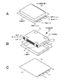
- 3A to 3C are exploded perspective views showing the configuration of a laminated film type non-aqueous electrolyte battery using a laminated electrode body.
- FIG. 4 is an exploded perspective view showing a configuration example of a simple battery pack.
- FIG. 1 is an exploded perspective view showing a configuration of a laminated film type nonaqueous electrolyte battery according to a first embodiment of the present technology.
- 2A is a cross-sectional view showing a cross-sectional configuration along the line II of the spirally wound electrode body
- FIG. 5A is a schematic perspective view showing the appearance of a simple battery pack.
- FIG. 5B is a schematic perspective view showing the appearance of a simple battery pack.
- FIG. 6 is a block diagram illustrating a circuit configuration example of the battery pack according to the embodiment of the present technology.
- FIG. 7 is a schematic view showing an example applied to a residential power storage system using the nonaqueous electrolyte battery of the present technology.
- FIG. 8 is a schematic diagram schematically illustrating an example of a configuration of a hybrid vehicle that employs a series hybrid system to which the present technology is applied.
- FIG. 9 is a schematic diagram for explaining the battery bending test.
- FIG. 10 is a schematic cross-sectional view for explaining the battery bending test.
- Patent Document 1 Japanese Patent Application Laid-Open No. 2010-198757 proposes mixing particles such as alumina in the gel electrolyte to improve the strength of the gel electrolyte. .
- a gel electrolyte (a gel electrolyte made into a sol with a solvent or dissolved in heat to form a hot melt) in advance is formed on an electrode (or a separator) and then solidified. Then, an electrode and a separator are laminated
- the gel electrolyte When forming the power generation element, the gel electrolyte is applied to at least the entire surface of the active material mixture layer (active material layer), and in particular, the gel electrolyte should be sufficiently applied to the cut end surface including the active material mixture layer of the electrode. is important. Insufficient electrolyte creates a part that cannot contribute to the charging reaction, causing capacity loss, but also causing burrs generated on the cut end face, dropped conductive agent, metal ion elution due to high potential application phenomenon, etc. It is because it becomes the cause of.
- a gel electrolyte mixed with particles such as alumina is sufficiently applied to the cut end surface of the electrode, a gel electrolyte layer having a width wider than the width of the electrode is formed, and the gel electrolyte layer is formed from both ends in the width direction of the electrode. Will protrude in the width direction. In this state after coating, the gel electrolyte mixed with particles such as alumina is clouded, making it difficult to distinguish the outline of the electrode viewed through the gel electrolyte.
- the present technology improves the transparency of the gel electrolyte, thereby ensuring safety without sacrificing capacity, battery, electrolyte, battery pack, electronic device, electric vehicle, power storage device And providing a power system.
- a laminated film type nonaqueous electrolyte battery (battery) will be described.
- This nonaqueous electrolyte battery is, for example, a nonaqueous electrolyte secondary battery that can be charged and discharged, and is, for example, a lithium ion secondary battery.
- two structural examples (a 1st example and a 2nd example) of a laminate film type nonaqueous electrolyte battery are explained.
- FIG. 1 shows the configuration of the nonaqueous electrolyte battery 62 according to the first embodiment.
- This non-aqueous electrolyte battery 62 is a so-called laminate film type, in which a wound electrode body 50 to which a positive electrode lead 51 and a negative electrode lead 52 are attached is housed in a film-like exterior member 60.
- the positive electrode lead 51 and the negative electrode lead 52 are led out from the inside of the exterior member 60 toward the outside, for example, in the same direction.
- the positive electrode lead 51 and the negative electrode lead 52 are made of, for example, a metal material such as aluminum, copper, nickel, or stainless steel, and each have a thin plate shape or a mesh shape.
- the exterior member 60 is made of, for example, a laminate film in which resin layers are formed on both surfaces of a metal layer.
- an outer resin layer is formed on the surface of the metal layer that is exposed to the outside of the battery, and an inner resin layer is formed on the inner surface of the battery facing the power generation element such as the wound electrode body 50.
- the metal layer plays the most important role in preventing moisture, oxygen and light from entering and protecting the contents.
- Aluminum (Al) is most often used because of its lightness, extensibility, price and ease of processing.
- the outer resin layer has a beautiful appearance, toughness, flexibility, and the like, and a resin material such as nylon or polyethylene terephthalate (PET) is used. Since the inner resin layer is a portion that melts and fuses with heat or ultrasonic waves, a polyolefin resin is appropriate, and unstretched polypropylene (CPP) is often used.
- An adhesive layer may be provided between the metal layer, the outer resin layer, and the inner resin layer as necessary.
- the exterior member 60 is provided with a recess that accommodates the wound electrode body 50 formed by, for example, deep drawing from the inner resin layer side toward the outer resin layer, and the inner resin layer serves as the wound electrode body 50. It is arrange
- the inner resin layers facing each other of the exterior member 60 are in close contact with each other by fusion or the like at the outer edge of the recess.
- the adhesion film 61 is made of a resin material having high adhesion to a metal material, and is made of, for example, polyethylene, polypropylene, or a polyolefin resin such as modified polyethylene or modified polypropylene obtained by modifying these materials.
- the exterior member 60 may be made of a laminated film having another structure, a polymer film such as polypropylene, or a metal film, instead of the aluminum laminated film whose metal layer is made of aluminum (Al).
- FIG. 2A shows a cross-sectional structure taken along line II of the spirally wound electrode body 50 shown in FIG.
- FIG. 2B is a schematic cross-sectional view showing a part of a cross section along a direction orthogonal to the line II of the wound electrode body 50.
- the wound electrode body 50 is formed by laminating a belt-like positive electrode 53 and a belt-like negative electrode 54 via a belt-like separator 55 and a gel electrolyte layer 56, and winding the outermost peripheral portion. Is protected by a protective tape 57 as necessary.
- the relationship between the width of the strip-shaped positive electrode 53, the width of the strip-shaped negative electrode 54, and the width of the strip-shaped separator 55 is typically, for example, the width of the strip-shaped positive electrode 53 ⁇ the strip-shaped negative electrode 54. Width ⁇ the width of the strip-shaped separator 55.
- the gel electrolyte layer 56 is formed with a width wider than the width of the strip-like positive electrode 53 and the width of the strip-like negative electrode 54, and at least a part of both end faces in the width direction of the strip-like positive electrode 53 and both ends of the strip-like negative electrode 54 in the width direction. Covers at least part of the surface.
- the gel electrolyte layer 56 preferably covers all of both end faces of the positive electrode 53 and both end faces of the negative electrode 54.
- the positive electrode 53, the negative electrode 54, and the separator 55 are formed between the ends of the positive electrode 53, the negative electrode 54, and the end of the separator 55 so as to have a predetermined appropriate clearance in the width direction.
- the gel electrolyte layers 56 are stacked.
- the positive electrode 53 has a structure in which a positive electrode active material layer 53B is provided on one or both surfaces of the positive electrode current collector 53A.
- the positive electrode 53 is obtained by forming a positive electrode active material layer 53B containing a positive electrode active material on both surfaces of a positive electrode current collector 53A.
- a positive electrode current collector 53A for example, a metal foil such as an aluminum (Al) foil, a nickel (Ni) foil, or a stainless steel (SUS) foil can be used.
- the positive electrode active material layer 53B includes, for example, a positive electrode active material, a conductive agent, and a binder.
- a positive electrode active material any one or more of positive electrode materials capable of inserting and extracting lithium can be used, and other materials such as a binder and a conductive agent can be used as necessary. May be included.
- a lithium-containing compound As the positive electrode material capable of inserting and extracting lithium, for example, a lithium-containing compound is preferable. This is because a high energy density can be obtained.
- the lithium-containing compound include a composite oxide containing lithium and a transition metal element, and a phosphate compound containing lithium and a transition metal element.
- the group which consists of cobalt (Co), nickel (Ni), manganese (Mn), and iron (Fe) as a transition metal element is preferable. This is because a higher voltage can be obtained.
- a lithium-containing compound represented by Li x M1O 2 or Li y M2PO 4 can be used as the positive electrode material.
- M1 and M2 represent one or more transition metal elements.
- the values of x and y vary depending on the charge / discharge state of the battery, and are generally 0.05 ⁇ x ⁇ 1.10 and 0.05 ⁇ y ⁇ 1.10.
- Examples of the composite oxide containing lithium and a transition metal element include lithium cobalt composite oxide (Li x CoO 2 ), lithium nickel composite oxide (Li x NiO 2 ), and lithium nickel cobalt composite oxide (Li x Ni).
- lithium nickel cobalt manganese composite oxide Li x Ni (1-vw) Co v Mn w O 2 (0 ⁇ v + w ⁇ 1, v> 0, w > 0)
- lithium manganese composite oxide LiMn 2 O 4
- lithium manganese nickel composite oxide LiMn 2 ⁇ t N t O 4 (0 ⁇ t ⁇ 2) having a spinel structure.
- a complex oxide containing cobalt is preferable. This is because a high capacity can be obtained and excellent cycle characteristics can be obtained.
- Examples of the phosphate compound containing lithium and a transition metal element include a lithium iron phosphate compound (LiFePO 4 ) or a lithium iron manganese phosphate compound (LiFe 1-u Mn u PO 4 (0 ⁇ u ⁇ 1). ) And the like.
- lithium composite oxide examples include lithium cobaltate (LiCoO 2 ), lithium nickelate (LiNiO 2 ), and lithium manganate (LiMn 2 O 4 ).
- LiCoO 2 lithium cobaltate
- LiNiO 2 lithium nickelate
- LiMn 2 O 4 lithium manganate
- a solid solution in which a part of the transition metal element is substituted with another element can also be used.
- nickel cobalt composite lithium oxide LiNi 0.5 Co 0.5 O 2 , LiNi 0.8 Co 0.2 O 2, etc.
- composite particles in which the surfaces of particles made of any of the above lithium-containing compounds are coated with fine particles made of any of the other lithium-containing compounds can be used. Good.
- positive electrode materials capable of inserting and extracting lithium include oxides such as vanadium oxide (V 2 O 5 ), titanium dioxide (TiO 2 ), manganese dioxide (MnO 2 ), and iron disulfide. (FeS 2 ), disulfides such as titanium disulfide (TiS 2 ) and molybdenum disulfide (MoS 2 ), and chalcogenides containing no lithium such as niobium diselenide (NbSe 2 ) (particularly layered compounds and spinel compounds) ), Lithium-containing compounds containing lithium, and conductive polymers such as sulfur, polyaniline, polythiophene, polyacetylene, or polypyrrole.
- the positive electrode material capable of inserting and extracting lithium may be other than the above. Further, two or more kinds of the series of positive electrode materials described above may be mixed in any combination.
- a carbon material such as carbon black or graphite
- the binder include resin materials such as polyvinylidene fluoride (PVdF), polytetrafluoroethylene (PTFE), polyacrylonitrile (PAN), styrene butadiene rubber (SBR), and carboxymethyl cellulose (CMC), and these resin materials. At least one selected from a copolymer or the like mainly composed of is used.
- the positive electrode 53 has a positive electrode lead 51 connected to one end of the positive electrode current collector 53A by spot welding or ultrasonic welding.
- the positive electrode lead 51 is preferably a metal foil or a mesh-like one, but there is no problem even if it is not a metal as long as it is electrochemically and chemically stable and can conduct electricity. Examples of the material of the positive electrode lead 51 include aluminum (Al) and nickel (Ni).
- the negative electrode 54 has a structure in which a negative electrode active material layer 54B is provided on one surface or both surfaces of a negative electrode current collector 54A, and the negative electrode active material layer 54B and the positive electrode active material layer 53B are arranged to face each other. Yes.
- the negative electrode active material layer 54B may be provided only on one surface of the negative electrode current collector 54A.
- the negative electrode current collector 54A is made of, for example, a metal foil such as a copper foil.
- the negative electrode active material layer 54B includes one or more negative electrode materials capable of occluding and releasing lithium as the negative electrode active material, and the positive electrode active material layer 53B as necessary. Other materials such as a binder and a conductive agent similar to those described above may be included.
- the electrochemical equivalent of the negative electrode material capable of inserting and extracting lithium is larger than the electrochemical equivalent of the positive electrode 53, and theoretically, the negative electrode 54 is in the middle of charging. Lithium metal is prevented from precipitating.
- the nonaqueous electrolyte battery 62 is designed such that the open circuit voltage (that is, the battery voltage) in the fully charged state is in the range of, for example, 2.80 V or more and 6.00 V or less.
- the open circuit voltage in a fully charged state is, for example, 4.20 V or more and 6. It is designed to be within the range of 00V or less.
- the open circuit voltage in the fully charged state is preferably 4.25V or more and 6.00V or less.
- the open circuit voltage in the fully charged state is 4.25 V or higher
- the amount of lithium released per unit mass is increased even with the same positive electrode active material as compared to the 4.20 V battery. Accordingly, the amounts of the positive electrode active material and the negative electrode active material are adjusted. Thereby, a high energy density can be obtained.
- Examples of the negative electrode material capable of inserting and extracting lithium include non-graphitizable carbon, graphitizable carbon, graphite, pyrolytic carbons, cokes, glassy carbons, and fired organic polymer compounds And carbon materials such as carbon fiber and activated carbon.
- examples of coke include pitch coke, needle coke, and petroleum coke.
- An organic polymer compound fired body is a carbonized material obtained by firing a polymer material such as a phenol resin or a furan resin at an appropriate temperature, and part of it is non-graphitizable carbon or graphitizable carbon.
- These carbon materials are preferable because the change in crystal structure that occurs during charge and discharge is very small, a high charge and discharge capacity can be obtained, and good cycle characteristics can be obtained.
- graphite is preferable because it has a high electrochemical equivalent and can provide a high energy density.
- non-graphitizable carbon is preferable because excellent cycle characteristics can be obtained.
- those having a low charge / discharge potential, specifically, those having a charge / discharge potential close to that of lithium metal are preferable because a high energy density of the battery can be easily realized.
- lithium can be inserted and extracted, and at least one of a metal element and a metalloid element can be used.
- a material containing as a constituent element is included. This is because a high energy density can be obtained by using such a material. In particular, the use with a carbon material is more preferable because a high energy density can be obtained and excellent cycle characteristics can be obtained.
- the negative electrode material may be a single element, alloy or compound of a metal element or metalloid element, or may have at least a part of one or more of these phases.
- the alloy includes an alloy including one or more metal elements and one or more metalloid elements in addition to an alloy composed of two or more metal elements.
- the nonmetallic element may be included.
- Examples of the metal element or metalloid element constituting the negative electrode material include a metal element or metalloid element capable of forming an alloy with lithium.
- a metal element or metalloid element capable of forming an alloy with lithium.
- the negative electrode material preferably includes a 4B group metal element or metalloid element in the short periodic table as a constituent element, and more preferably includes at least one of silicon (Si) and tin (Sn) as a constituent element. And particularly preferably those containing at least silicon. This is because silicon (Si) and tin (Sn) have a large ability to occlude and release lithium, and a high energy density can be obtained.
- Examples of the negative electrode material having at least one of silicon and tin include at least a part of a simple substance, an alloy or a compound of silicon, a simple substance, an alloy or a compound of tin, or one or more phases thereof. The material which has in is mentioned.
- tin alloys include silicon (Si), nickel (Ni), copper (Cu), iron (Fe), cobalt (Co), and manganese (Mn) as second constituent elements other than tin (Sn).
- tin (Sn) compound or silicon (Si) compound examples include those containing oxygen (O) or carbon (C).
- O oxygen
- C carbon
- the above-described compounds are used. Two constituent elements may be included.
- cobalt (Co), tin (Sn), and carbon (C) are included as constituent elements, and the carbon content is 9.9 mass% or more and 29.7 mass% or less.
- SnCoC containing material whose ratio of cobalt (Co) with respect to the sum total of tin (Sn) and cobalt (Co) is 30 mass% or more and 70 mass% or less is preferable. This is because a high energy density can be obtained in such a composition range, and excellent cycle characteristics can be obtained.
- This SnCoC-containing material may further contain other constituent elements as necessary.
- other constituent elements include silicon (Si), iron (Fe), nickel (Ni), chromium (Cr), indium (In), niobium (Nb), germanium (Ge), titanium (Ti), and molybdenum.
- Mo silicon
- Al aluminum
- phosphorus (P) gallium
- Ga bismuth
- This SnCoC-containing material has a phase containing tin (Sn), cobalt (Co), and carbon (C), and this phase has a low crystallinity or an amorphous structure. It is preferable.
- this SnCoC-containing material it is preferable that at least a part of carbon (C) as a constituent element is bonded to a metal element or a metalloid element as another constituent element.
- the decrease in cycle characteristics is considered to be due to aggregation or crystallization of tin (Sn) or the like.
- the combination of carbon (C) with other elements suppresses such aggregation or crystallization. Because it can.
- XPS X-ray photoelectron spectroscopy
- the peak of the carbon 1s orbital (C1s) appears at 284.5 eV in an energy calibrated apparatus so that the peak of the gold atom 4f orbital (Au4f) is obtained at 84.0 eV if it is graphite. .
- Au4f gold atom 4f orbital
- it will appear at 284.8 eV.
- the charge density of the carbon element increases, for example, when carbon is bonded to a metal element or a metalloid element, the C1s peak appears in a region lower than 284.5 eV.
- the peak of the synthetic wave of C1s obtained for the SnCoC-containing material appears in a region lower than 284.5 eV
- at least a part of the carbon contained in the SnCoC-containing material is a metal element or a half of other constituent elements. Combined with metal elements.
- the C1s peak is used to correct the energy axis of the spectrum.
- the C1s peak of the surface-contaminated carbon is set to 284.8 eV, which is used as an energy standard.
- the waveform of the C1s peak is obtained as a shape including the surface contamination carbon peak and the carbon peak in the SnCoC-containing material. Therefore, by analyzing using, for example, commercially available software, the surface contamination The carbon peak and the carbon peak in the SnCoC-containing material are separated. In the waveform analysis, the position of the main peak existing on the lowest bound energy side is used as the energy reference (284.8 eV).
- Examples of the negative electrode material capable of occluding and releasing lithium include metal oxides and polymer compounds capable of occluding and releasing lithium.
- Examples of the metal oxide include lithium titanium oxide containing titanium and lithium such as lithium titanate (Li 4 Ti 5 O 12 ), iron oxide, ruthenium oxide, or molybdenum oxide.
- Examples of the polymer compound include polyacetylene, polyaniline, polypyrrole, and the like.
- the separator 55 is a porous film made of an insulating film having a high ion permeability and a predetermined mechanical strength. A non-aqueous electrolyte is held in the pores of the separator 55.
- a polyolefin resin such as polypropylene or polyethylene, an acrylic resin, a styrene resin, a polyester resin, or a nylon resin is preferably used as the resin material constituting the separator 55.
- polyethylene such as low density polyethylene, high density polyethylene, linear polyethylene or the like, or a low molecular weight wax component thereof, or polyolefin resin such as polypropylene is suitable because it has an appropriate melting temperature and is easily available.
- a material including a porous film made of a polyolefin resin is excellent in separability between the positive electrode 53 and the negative electrode 54 and can further reduce a decrease in internal short circuit.
- the thickness of the separator 55 can be arbitrarily set as long as it is equal to or greater than the thickness that can maintain the required strength.
- the separator 55 insulates between the positive electrode 53 and the negative electrode 54 to prevent a short circuit and the like, and has ion permeability for suitably performing a battery reaction via the separator 55, and the battery reaction in the battery. It is preferable to set the thickness so that the volumetric efficiency of the active material layer contributing to the above can be as high as possible.
- the thickness of the separator 55 is preferably, for example, 4 ⁇ m or more and 20 ⁇ m or less.
- the gel electrolyte layer 56 includes a matrix polymer compound that is a filler and a resin, and a nonaqueous electrolytic solution (electrolytic solution) containing a solvent and an electrolyte salt.
- the gel electrolyte layer 56 is a layer made of a gel electrolyte in which a non-aqueous electrolyte is held by a matrix polymer compound.
- the gel electrolyte layer 56 has a so-called gel shape, for example, by impregnating a matrix polymer compound with an electrolytic solution and swelling the matrix polymer compound.
- the gel-like matrix polymer itself that absorbs and holds the electrolytic solution functions as an ionic conductor. Moreover, since the gel electrolyte layer 56 contains a filler, the strength and the like of the gel electrolyte layer 56 are improved, and characteristics such as safety can be improved.
- the filler included in the gel electrolyte layer 56 includes particles having a refractive index within a predetermined range and a particle diameter within a predetermined range, and At least one of the mass ratio of the gel electrolyte layer 56 to the resin (particle / resin) and the mass ratio of the particle to the electrolyte salt (particle / electrolyte salt) is within a predetermined range. Since the gel electrolyte layer 56 is transparent, it can be solved that the safety of the battery cannot be ensured without sacrificing the capacity due to the gel electrolyte layer 56 not being transparent.
- the gel electrolyte layer 56 is configured as described above in order to improve the transparency of the gel electrolyte layer 56 .
- white inorganic powders such as alumina particles are formed of colorless and transparent particles, but are white due to light scattering.
- the inventors of the present invention have a diameter in the range almost equal to the wavelength of visible light (visible light of blue, green, yellow, orange, red) (greater than 450 nm and less than 750 nm). It was found to occur on the particle surface. Then, it has been found that scattering can be avoided by selecting particles having a particle size smaller than the above wavelength range or by selecting particles having a particle size larger than the above wavelength range.
- particles in the range of 50 nm to 450 nm, or particles of 750 nm to 10000 nm are effective.
- the particle diameter is too small, the viscosity of the coating material is higher than that suitable for application, and thus it is preferably 50 nm or more.
- the particle diameter is larger than 10,000 nm, there are cases where the particle becomes larger than the thickness to be applied, and the thickness of the battery does not work as designed.
- the particle diameter of the particles contained in the gel electrolyte layer 56 can be defined by the value of the particle diameter D50. If the particle diameter D50 is in the above range (particles of 50 nm to 450 nm, or 750 nm to 10000 nm), for example, a part of the particle size distribution of D10, D90, etc. Even in the wavelength region (over 450 nm and less than 750 nm), the transparency as a whole is maintained. Even when the particles are aggregated to form secondary particles, the size of the surface irregularities of the secondary particles is equal to the wavelength of light scattering, so the particle diameter of one particle that is the basis of the irregularities is important. It is.
- Solid electrolytes contain many electrolyte components, so there are many cases in which the refractive index is 1.3 or more and 1.8 or less. (Preferably 2.1 or less), light advances straight when passing through the electrolyte (gel electrolyte) particles.
- the mass ratio of the gel electrolyte layer 56 to the resin (particle / resin) and the mass ratio of the particle to the electrolyte salt (particle / electrolyte salt) is within a predetermined range (15/85 or more). 90/10 or less). Since the refractive index of the gel electrolyte and the refractive index of the particles are not the same, the gel electrolyte layer can be formed by reducing the particle ratio by setting the above mass ratio range so that it does not become dark even if white turbidity occurs. The transparency of 56 can be ensured. In addition, from the viewpoint of ensuring the transparency of the gel electrolyte layer 56, the lower the ratio of the particles, the better. However, if the ratio of the particles is too low, the strength of the gel electrolyte layer 56 tends to decrease. A value is set.
- the content ratio of the electrolyte salt to the gel electrolyte is preferably within a predetermined range.
- the content ratio of the electrolyte salt is larger, the refractive index of the gel electrolyte approaches the refractive index of the particles.
- the content ratio of the electrolyte salt is too large, the ion migration resistance of the battery increases and the output becomes worse.
- “transparent” means that the outline of the electrode (the separator 55 when formed on the separator 55) can be visually recognized through the gel electrolyte layer 56 formed on the electrode (or the separator 55). It means transparency. The case where the outline of the electrode (or separator 55) can be clearly seen through the gel electrolyte layer 56, as well as the case where the outline of the electrode (or separator 55) can be seen slightly, is included in “transparent”. The state where the gel electrolyte layer 56 becomes translucent, colored, cloudy, etc., and the outline of the electrode (or separator 55) cannot be completely seen through the gel electrolyte layer 56 is not included in “transparent”. In addition, it is preferable that the outline of the electrode (or the separator 55) can be visually recognized more clearly (higher transparency) through the gel electrolyte layer 56 because it is easier to ensure safety.
- the thickness of the gel electrolyte layer 56 is, for example, preferably 1 ⁇ m to 15 ⁇ m, and more preferably 2 ⁇ m to 8 ⁇ m. Since scattering cannot be completely eliminated, the transparency is reduced when the thickness of the gel electrolyte layer 56 is thick. Therefore, in order to make the end of the electrode stand out, it is necessary to reduce the white turbidity on the electrode and ensure the contrast. . Therefore, it is preferable to form the gel electrolyte layer 56 thinly. However, when the thickness of the gel electrolyte layer 56 is smaller than 1 ⁇ m, the battery performance tends to be lowered. On the other hand, when the gel electrolyte layer 56 exceeds 15 ⁇ m, the distance between the electrodes increases, so that the energy density per volume tends to decrease.
- the nonaqueous electrolytic solution includes an electrolyte salt and a nonaqueous solvent that dissolves the electrolyte salt.
- the electrolyte salt contains, for example, one or more light metal compounds such as lithium salts.
- the lithium salt include lithium hexafluorophosphate (LiPF 6 ), lithium tetrafluoroborate (LiBF 4 ), lithium perchlorate (LiClO 4 ), lithium hexafluoroarsenate (LiAsF 6 ), lithium tetraphenylborate (LiB (C 6 H 5) 4), methanesulfonic acid lithium (LiCH 3 SO 3), lithium trifluoromethanesulfonate (LiCF 3 SO 3), tetrachloroaluminate lithium (LiAlCl 4), six Examples thereof include dilithium fluorosilicate (Li 2 SiF 6 ), lithium chloride (LiCl), and lithium bromide (LiBr).
- At least one selected from the group consisting of lithium hexafluorophosphate, lithium tetrafluoroborate, lithium perchlorate, and lithium hexafluoroarsenate is preferable, and lithium hexafluorophosphate is more preferable.
- Nonaqueous solvent examples include lactone solvents such as ⁇ -butyrolactone, ⁇ -valerolactone, ⁇ -valerolactone, and ⁇ -caprolactone, ethylene carbonate, propylene carbonate, butylene carbonate, vinylene carbonate, dimethyl carbonate, ethyl methyl carbonate, Carbonate ester solvents such as diethyl carbonate, ether solvents such as 1,2-dimethoxyethane, 1-ethoxy-2-methoxyethane, 1,2-diethoxyethane, tetrahydrofuran or 2-methyltetrahydrofuran, and nitriles such as acetonitrile
- Nonaqueous solvents such as solvents, sulfolane-based solvents, phosphoric acids, phosphate ester solvents, and pyrrolidones are exemplified. Any one type of solvent may be used alone, or two or more types may be mixed and used.
- a mixture of a cyclic carbonate and a chain carbonate as the non-aqueous solvent, and it may contain a compound in which a part or all of the hydrogen of the cyclic carbonate or the chain carbonate includes a fluorination.
- the fluorinated compounds include fluoroethylene carbonate (4-fluoro-1,3-dioxolan-2-one: FEC) and difluoroethylene carbonate (4,5-difluoro-1,3-dioxolan-2-one: DFEC) is preferably used.
- the negative electrode 54 containing a compound such as silicon (Si), tin (Sn), or germanium (Ge) is used as the negative electrode active material, charge / discharge cycle characteristics can be improved.
- difluoroethylene carbonate is preferably used as the non-aqueous solvent. This is because the cycle characteristic improvement effect is excellent.
- resin As the resin, it is possible to use a matrix polymer compound that retains the electrolytic solution and has a property compatible with a solvent.
- resins include fluorine-containing resins such as polyvinylidene fluoride and polytetrafluoroethylene, fluorine-containing rubbers such as vinylidene fluoride-tetrafluoroethylene copolymer and ethylene-tetrafluoroethylene copolymer, and styrene-butadiene copolymer.
- filler As the filler contained in the gel electrolyte layer 56, from the viewpoint of reducing light scattering and improving the transparency of the gel electrolyte layer 56, particles having a particle diameter within a predetermined range and a refractive index within a predetermined range are used. Use.
- the particle diameter D50 is set to 50 nm to 450 nm or 750 nm to 10000 nm. This is because the transparency of the entire electrolyte can be secured by using particles having a particle diameter in these ranges. Further, when the particle diameter is less than 50 nm, the particle diameter is too small and becomes higher than the paint viscosity appropriate for application. This is because when the particle diameter is larger than 10,000 nm, there are cases in which the particle becomes larger than the thickness to be applied, and the thickness of the battery does not go as designed.
- the upper limit of the particle diameter D50 in the range of 750 nm to 10,000 nm is 8000 nm or less, preferably 7000 nm or less, more preferably 5000 nm or less from the viewpoint of battery capacity.
- the lower limit of the above range of 750 nm or more and 10,000 nm or less is preferably 800 nm or more, more preferably 2000 nm or more, from the viewpoint of further improving the transparency of the gel electrolyte.
- the upper limit of the particle diameter D50 in the range of 50 nm to 450 nm is preferably 400 nm or less, and more preferably 300 nm or less, from the viewpoint of further improving the transparency of the gel electrolyte layer 56.
- the particle diameter of the particles is such that, in addition to the particle diameter D50, the particle diameter D40 and the particle diameter D60 are 50 nm or more and 450 nm or less, or 750 nm or more and 10,000 nm.
- the particle diameter D50 of the particles is preferably 50 nm to 450 nm
- the particle diameter D40 is 50 nm to 450 nm
- the particle diameter D60 is preferably 50 nm to 450 nm.
- the particle diameter D50 of the particles is preferably 750 nm or more and 10,000 nm or less
- the particle diameter D40 is 750 nm or more and 10,000 nm or less
- the particle diameter D60 is preferably 750 nm or more and 10,000 nm or less.
- the particle diameter D50 of the particles is, for example, a cumulative volume of 50% calculated from the particle side having a small particle diameter in the particle size distribution measured by laser diffractometry after removing the gel electrolyte component from the gel electrolyte layer 56.
- the particle size Further, from the measured particle size distribution, a particle diameter D40 value of 40% cumulative volume and a particle diameter D60 of 60% cumulative volume can be obtained.
- the shape of the particles is typically, for example, a spherical shape, a plate shape such as a scale shape or a flake shape, or a flat shape such as a needle shape (sometimes referred to as a flat shape), but is not limited thereto. Is not to be done.
- the shape of the particles is preferably a non-spherical shape other than a spherical shape from the viewpoint of reducing light scattering at the grain boundary and improving the transparency, and among the non-spherical shapes, a plate shape such as a scale shape or a flake shape, or a needle shape A flat shape such as is more preferable.
- grains which consist of a single crystal or a few single crystals are preferable rather than the secondary particle
- the spherical shape includes not only a true spherical shape but also a shape in which the true spherical shape is slightly flat or distorted, a shape in which irregularities are formed on the true spherical surface, or a shape in which these shapes are combined.
- the flat shape refers to a particle having a ratio (long side / short side) of the long side of the particle to the short side of the particle of 2/1 or more.
- a plate shape such as a scale shape or a flake shape and a needle shape are a kind of flat shape, and a thin and flat shape is referred to as a plate shape, and an elongated shape like a needle is referred to as a needle shape.
- Scale-like and flake-like shapes are types of plates.
- the inventors of the present application have selected at least one of the maximum value and the minimum value of the projected dimension from each direction of the particle when the flat shape particle is selected among these shapes. It has been found that transparency can be further maintained by entering 50 nm or more and 450 nm or less, or 750 nm or more and 10,000 nm or less.
- the maximum length of the main surface is preferably 750 nm or more and 10,000 nm or less, and the thickness is preferably in the range of 50 nm or more and 450 nm or less.
- the length is 50 nm or more and 10,000 nm or less, and the thickness is in the range of 50 nm or more and 450 nm or less, there is little light scattering.
- having spherical particles having a diameter of 350 nm or more and 850 nm or less, which is the visible light wavelength range is optimal for balancing the reduction in the effect of paint viscosity and battery characteristics and the improvement in strength with the electrolyte. . Therefore, if the volume per particle is set to the same range as the spherical particles having the diameter in the above range, selecting a plate-like or needle-like particle in the projected dimension range can obtain transparency without breaking the balance. It is suitable for.
- the refractive index of the particles is 1.3 or more and less than 2.4 and 1.3 or more and 2.1 or less from the viewpoint of suppressing light scattering and ensuring the transparency of the gel electrolyte layer 56. preferable. This is in order to suppress a decrease in transparency due to light refraction due to the difference in refractive index between the gel electrolyte and the particles (difference that the solid has a high refractive index and the liquid has a low refractive index).
- the lower refractive index is 1.3 or more and less than 2.4.
- particles in the range of 1.3 to 2.1 are used.
- the particles for example, at least one of inorganic particles and organic particles can be used.
- the inorganic particles include particles of metal oxide, sulfate compound, carbonate compound, metal hydroxide, metal carbide, metal nitride, metal fluoride, phosphate compound, mineral, and the like.
- particles having electrical insulation properties are typically used.
- the surface of the particles (fine particles) of the conductive material is electrically insulated by performing surface treatment with the electrical insulation material. Sedimented particles (fine particles) may be used.
- metal oxide examples include silicon oxide (SiO 2 , silica (silica powder, quartz glass, glass beads, diatomaceous earth, wet or dry synthetic products, etc.), wet synthetic products such as colloidal silica, and dry synthetic products such as fumed silica.
- Zinc oxide (ZnO), tin oxide (SnO), magnesium oxide (magnesia, MgO), antimony oxide (Sb 2 O 3 ), aluminum oxide (alumina, Al 2 O 3 ), etc. are preferably used. be able to.
- magnesium sulfate (MgSO 4 ), calcium sulfate (CaSO 4 ), barium sulfate (BaSO 4 ), strontium sulfate (SrSO 4 ) and the like can be suitably used.
- carbonate compound magnesium carbonate (MgCO 3 , magnesite), calcium carbonate (CaCO 3 , calcite), barium carbonate (BaCO 3 ), lithium carbonate (Li 2 CO 3 ) and the like can be suitably used.
- metal carbide boron carbide (B 4 C) or the like can be suitably used.
- metal nitride silicon nitride (Si 3 N 4 ), boron nitride (BN), aluminum nitride (AlN), titanium nitride (TiN), or the like can be suitably used.
- lithium fluoride LiF
- aluminum fluoride AlF 3
- calcium fluoride CaF 2
- barium fluoride BaF 2
- magnesium fluoride or the like
- phosphate compound trilithium phosphate (Li 3 PO 4 ), magnesium phosphate, magnesium hydrogen phosphate, ammonium polyphosphate, and the like can be suitably used.
- Examples of minerals include silicate minerals, carbonate minerals, and oxide minerals.
- Silicate minerals are classified into nesosilicate minerals, solosilicate minerals, cyclosilicate minerals, inosilicate minerals, layered (phyllo) silicate minerals, and tectosilicate minerals based on their crystal structures. . Some are classified into fibrous silicate minerals called asbestos based on a classification standard different from the crystal structure.
- the nesosilicate mineral is an island-like tetrahedral silicate mineral made of an independent Si—O tetrahedron ([SiO 4 ] 4 ⁇ ).
- Examples of the nesosilicate mineral include those corresponding to olivines and meteorites.
- olivine a continuous solid solution of Mg 2 SiO 4 (magnerite olivine) and Fe 2 SiO 4 (iron olivine)
- magnesium silicate forsterite (bitter) Earth olivine
- Mg 2 SiO 4 aluminum silicate
- Al 2 SiO 5 aluminum silicate
- Zn 2 SiO 4 zirconium silicate
- mullite 3Al 2 O 3 .2SiO 2 to 2Al 2 O 3 .SiO 2
- the solosilicate mineral is a group structure type silicate mineral composed of a Si—O tetrahedral double bond group ([Si 2 O 7 ] 6 ⁇ , [Si 5 O 16 ] 12 ⁇ ).
- Examples of the silicate mineral include those corresponding to vesuvite and chlorite.
- the cyclosilicate mineral is composed of a Si—O tetrahedral finite (3-6) ring ([Si 3 O 9 ] 6 ⁇ , [Si 4 O 12 ] 8 ⁇ , [Si 6 O 18 ] 12. - ) An annular silicate mineral.
- Examples of the cyclosilicate mineral include beryl and tourmaline.
- Inosilicate minerals have an infinite number of Si—O tetrahedral linkages, and are chain-like ([Si 2 O 6 ] 4 ⁇ ) and belt-like ([Si 3 O 9 ] 6 ⁇ , [Si 4 O 11 ] 6 - , [Si 5 O 15 ] 10- , [Si 7 O 21 ] 14- ).
- Examples of the inosilicate mineral include those corresponding to pyroxenes such as calcium silicate (wollastonite, CaSiO 3 ), and those corresponding to amphibole.
- the layered silicate mineral is a layered silicate mineral that forms a network bond of Si—O tetrahedra ([SiO 4 ] 4 ⁇ ).
- SiO 4 tetrahedra
- the specific example of a layered silicate mineral is mentioned later.
- the tectosilicate mineral is a three-dimensional network structure type silicate mineral in which a Si—O tetrahedron ([SiO 4 ] 4 ⁇ ) forms a three-dimensional network bond.
- the tectosilicates minerals, quartz, feldspars, zeolites, and the like, zeolite (M 2 / n O ⁇ Al 2 O 3 ⁇ xSiO 2 ⁇ yH 2 O, M is a metal element, n represents the valence of M, x ⁇ 2, y ⁇ 0) aluminosilicate zeolite such as (aM 2 O ⁇ bAl 2 O 3 ⁇ cSiO 2 ⁇ dH 2 O, M is as defined above .a, b, c, d are each 1 or more And the like.) And the like.
- Examples of asbestos include chrysotile, amosite and anthophinite.
- the carbonate minerals dolomite (dolomite, CaMg (CO 3) 2) , hydrotalcite (Mg 6 Al 2 (CO 3 ) (OH) 16 ⁇ 4 (H 2 O)) and the like.
- oxide mineral examples include spinel (MgAl 2 O 4 ).
- Examples of other minerals include barium titanate (BaTiO 3 ) and strontium titanate (SrTiO 3 ).
- the mineral may be a natural mineral or an artificial mineral.
- clay minerals include a crystalline clay mineral, an amorphous or quasicrystalline clay mineral, and the like.
- crystalline clay minerals include layered silicate minerals, those having a structure similar to layered silicates, silicate minerals such as other silicate minerals, and layered carbonate minerals.
- the layered silicate mineral includes a Si—O tetrahedral sheet and an octahedral sheet such as Al—O and Mg—O combined with the tetrahedral sheet.
- Layered silicates are typically classified by the number of tetrahedral and octahedral sheets, the number of cations in the octahedron, and the layer charge.
- the layered silicate mineral may be one obtained by substituting all or part of metal ions between layers with organic ammonium ions or the like.
- the layered silicate minerals include a kaolinite-serpentine group with a 1: 1 type structure, a pyrophyllite-talc group, a smectite group, a vermiculite group, a mica group with a 2: 1 type structure. And those corresponding to the brittle mica (brittle mica) family, chlorite (chlorite group), and the like.
- Examples of the kaolinite-serpentine family include chrysotile, antigolite, lizardite, kaolinite (Al 2 Si 2 O 5 (OH) 4 ), and dickite.
- Examples of the pyrophyllite-talc family include talc (Mg 3 Si 4 O 10 (OH) 2 ), willemsite, and granite (pyrophyllite, Al 2 Si 4 O 10 (OH) 2. ) And the like.
- smectite group examples include saponite [(Ca / 2, Na) 0.33 (Mg, Fe 2+ ) 3 (Si, Al) 4 O 10 (OH) 2 .4H 2 O], hectorite, Sauconite, montmorillonite ⁇ (Na, Ca) 0.33 (Al, Mg) 2Si 4 O 10 (OH) 2 .nH 2 O, where clay containing montmorillonite as a main component is called bentonite ⁇ , beidellite, nontrite, etc. .
- Examples of the mica (mica) family include, for example, moscovite (muscovite, KAl 2 (AlSi 3 ) O 10 (OH) 2 ) sericite (sericite), phlogopite (phlogopite), biotite, lipidite ( Lithia mica) and the like.
- Examples of those belonging to the brittle mica (brittle mica) family include margarite, clintonite, and anandite.
- Examples of the chlorite (chlorite) family include kukkeite, sudokuite, clinochlore, chamosite, and nimite.
- a hydrous magnesium silicate having a 2: 1 ribbon structure in which a tetrahedron sheet arranged in a ribbon shape is connected to a tetrahedron sheet arranged in an adjacent ribbon shape while reversing the apex.
- the hydrous magnesium silicate include sepiolite (foamstone: Mg 9 Si 12 O 30 (OH) 6 (OH 2 ) 4 .6H 2 O), palygorskite and the like.
- silicate minerals zeolites (M 2 / n O ⁇ Al 2 O 3 ⁇ xSiO 2 ⁇ yH 2 O, M is a metal element, n represents the valence of M, x ⁇ 2, y ⁇ 0) , etc.
- the layered carbonate minerals hydrotalcite (Mg 6 Al 2 (CO 3 ) (OH) 16 ⁇ 4 (H 2 O)) and the like.
- amorphous or quasicrystalline clay mineral examples include bingellite, imogolite (Al 2 SiO 3 (OH)), and allophane.
- inorganic particles may be used alone or in combination of two or more.
- the inorganic particles also have oxidation resistance.
- the gel electrolyte layer 56 is provided between the positive electrode 53 and the separator 55, the inorganic particles have strong resistance to an oxidizing environment in the vicinity of the positive electrode during charging.
- the particles may be organic particles.
- Materials constituting the organic particles include melamine, melamine cyanurate, melamine polyphosphate, cross-linked polymethyl methacrylate (cross-linked PMMA), polyethylene, polypropylene, polystyrene, polytetrafluoroethylene, polyvinylidene fluoride, polyamide, polyimide, melamine Resins, phenol resins, epoxy resins and the like can be mentioned. These materials may be used alone or in combination of two or more.
- the ratio of the particles the better. However, if the ratio of the particles is too low, the strength of the gel electrolyte layer 56 tends to decrease. A value is set.
- At least one of the mass ratio (particle / resin) and the mass ratio (particle / electrolyte salt) is within the above range (15/85 or more and 90/10 or less). ). If one of the mass ratio (particle / resin) and the mass ratio (particle / electrolyte salt) is within the above range, the transparency of the gel electrolyte layer 56 can be secured. If both the mass ratio (particle / resin) and the mass ratio (particle / electrolyte salt) are within the above range, it is preferable because the transparency can be further improved.
- the content of the particles is preferably 5.2% by mass or more and 50.0% by mass or less with respect to the mass of the electrolyte from the viewpoint that the refractive index of the gel electrolyte can be brought close to the particles and the transparency can be further improved. More preferably, the content is 5.2% by mass or more and 30.8% by mass or less.
- the content of the resin is preferably 5.6% by mass or more and 30.8% by mass or less with respect to the mass of the electrolyte, from the viewpoint that the refractive index of the gel electrolyte approaches the particles and the transparency can be further improved. More preferably, it is 7.7 mass% or more and 30.8 mass% or less. In addition, when there is more content of resin than 30.8 mass%, it exists in the tendency for the ion migration resistance of a battery to increase and for an output to fall.
- the content of the electrolyte salt is 5.6% by mass or more and 30.8% by mass or less with respect to the mass of the electrolyte from the viewpoint of making the refractive index of the gel electrolyte close to that of the filler particles and further improving the transparency. Preferably, it is 7.7 mass% or more and 30.8 mass% or less. In addition, when there is more content of electrolyte salt than 30.8 mass%, it exists in the tendency for the ion migration resistance of a battery to increase and for an output to fall.
- This nonaqueous electrolyte battery 62 can be manufactured as follows, for example.
- a positive electrode active material, a conductive agent, and a binder are mixed to prepare a positive electrode mixture, and the positive electrode mixture is dispersed in a solvent such as N-methyl-2-pyrrolidone to form a paste-like positive electrode mixture slurry Is made.
- the positive electrode mixture slurry is applied to the positive electrode current collector 53A, the solvent is dried, and the positive electrode active material layer 53B is formed by compression molding with a roll press or the like, and the positive electrode 53 is manufactured.
- a negative electrode active material and a binder are mixed to prepare a negative electrode mixture, and the negative electrode mixture is dispersed in a solvent such as N-methyl-2-pyrrolidone to prepare a paste-like negative electrode mixture slurry.
- this negative electrode mixture slurry is applied to the negative electrode current collector 54A, the solvent is dried, and the negative electrode active material layer 54B is formed by compression molding with a roll press machine or the like, and the negative electrode 54 is manufactured.
- the nonaqueous electrolytic solution is prepared by dissolving an electrolyte salt in a nonaqueous solvent.
- the positive electrode 53 on which the gel electrolyte layer 56 is formed and the negative electrode 54 on which the gel electrolyte layer 56 is formed are laminated through a separator 55 to form a laminate, and then the laminate is wound in the longitudinal direction.
- the wound electrode body 50 is formed by adhering the protective tape 57 to the outermost periphery.
- the wound electrode body 50 may be formed as follows. After applying the precursor solution to at least one side of both sides of the separator 55, the diluting solvent is volatilized. Thereby, the gel electrolyte layer 56 is formed on both surfaces of the separator 55.
- the positive lead 51 is attached to the end of the positive current collector 53A in advance by welding, and the negative lead 52 is attached to the end of the negative current collector 54A by welding.
- the positive electrode 53 and the negative electrode 54 are laminated through a separator 55 having a gel electrolyte layer 56 formed on both sides to form a laminated body, and then the laminated body is wound in the longitudinal direction to obtain a wound electrode body 50. .
- the accuracy of the clearance between the end of the positive electrode 53, the end of the negative electrode 54, and the end of the separator 55 with respect to an appropriate clearance is such that when the wound electrode body 50 is formed, the end of the electrode or the like is attached to a camera or the like Therefore, the gel electrolyte layer 56 is required to be transparent.
- the stacking and winding of the positive electrode 53, the negative electrode 54, and the separator 55 when forming the wound electrode body 50 typically involves, for example, a winding device (winder) for winding the positive electrode 53, the negative electrode 54, and the separator 55. And laminating and winding.
- a winding device for winding the positive electrode 53, the negative electrode 54, and the separator 55.
- laminating and winding At this time, a camera is installed in the winding device, the state of winding is photographed (for example, every rotation), and the photographed image data is sent to the image processing device.
- the edge position data of each electrode and / or separator is detected by image processing, and is wound between the positive electrode 53, the negative electrode 54, and the separator 55 based on, for example, the difference in edge position data of each member. Detect whether there is a shift.
- the feedback is fed back to the winding unit of the winding device, and the winding of the winding device is performed so that the edge positions of the positive electrode 53, the negative electrode 54, and the separator 55 coincide with the correct edge positions. Control part.
- photographing of the end portion of the coating object by photographing means such as a camera is performed through the gel electrolyte layer 56 formed on the coating object (the positive electrode 53, the negative electrode 54, or the separator 55).
- the gel electrolyte layer 56 is not transparent, the detection of the edge position to be applied is not successful, and winding deviation occurs.
- the edge position is detected only on one side on one side as a reference, and when winding misalignment occurs due to erroneous detection, the positive and negative edges on the opposite side of the reference one side may protrude from the separator, causing a short circuit. May occur.
- the gel electrolyte layer 56 formed on the application target is transparent, it is possible to eliminate the failure of detecting the edge position of the application target, and it is possible to suppress the occurrence of winding deviation. . Thereby, short circuit failure due to battery winding deviation can be avoided, and safety can be ensured.
- the wound electrode body 50 is sandwiched between the exterior members 60, and the outer edges of the exterior members 60 are sealed by thermal fusion or the like and sealed.
- an adhesion film 61 is inserted between the positive electrode lead 51 and the negative electrode lead 52 and the exterior member 60.
- the nonaqueous electrolyte battery 62 shown in FIGS. 1 and 2 is completed.
- FIG. 3A is an external view of the nonaqueous electrolyte battery 62 that houses the laminated electrode body 70.
- FIG. 3B is an exploded perspective view showing a state in which the laminated electrode body 70 is accommodated in the exterior member 60.
- 3C is an external view showing an external appearance of the nonaqueous electrolyte battery 62 shown in FIG. 3A from the bottom surface side.
- the laminated electrode body 70 uses a laminated electrode body 70 in which a rectangular positive electrode 73 and a rectangular negative electrode 74 are laminated via a rectangular separator 75 and fixed by a fixing member 76.
- the gel electrolyte layer is provided in contact with the positive electrode 73 and the negative electrode 74.
- a gel electrolyte layer (not shown) is provided between the positive electrode 73 and the separator 75 and between the negative electrode 74 and the separator 75. This gel electrolyte layer is the same as the gel electrolyte layer 56 of the first example.
- a positive electrode lead 71 connected to the positive electrode 73 and a negative electrode lead 72 connected to the negative electrode 74 are led out from the laminated electrode body 70, and the positive electrode lead 71, the negative electrode lead 72, and the exterior member 60 are in close contact with each other.
- a film 61 is provided.
- the ends of the four sides of the rectangular positive electrode 73, the four sides of the rectangular negative electrode 74, and the four sides of the rectangular separator 75 are each end.
- the positive electrode 73, the negative electrode 74, and the separator 75 are laminated via a gel electrolyte layer (not shown) formed therebetween so that there is a predetermined clearance therebetween.
- the gel electrolyte layer covers at least a part of the peripheral end surface of the positive electrode 73 and at least a part of the peripheral end surface of the negative electrode 74.
- the formation method of the gel electrolyte layer and the heat fusion method of the exterior member 60 are the same as in the first example.
- the edge position cannot be detected successfully, resulting in a laminating deviation.
- the detection of the edge position is performed only on two adjacent sides as a reference, and when a misalignment causes a stacking shift, the positive and negative edges on the opposite side of the two adjacent sides as a reference may protrude from the separator. There is a risk of short circuit.
- the gel electrolyte layer formed on the application target is transparent, it is possible to eliminate the failure of detecting the edge of the application target (electrode or separator 75). In addition, it is possible to suppress the occurrence of a deviation in the clearance (stacking deviation) between the edges of the positive electrode 73, the negative electrode 74, and the separator 75. Thereby, the short circuit defect of a battery can be avoided and safety
- Second Embodiment an example of a battery pack of a laminate film type battery (non-aqueous electrolyte battery) provided with the same gel electrolyte layer as in the first embodiment will be described.
- This battery pack is a simple battery pack (also referred to as a soft pack).
- a simple battery pack is built in an electronic device.
- a battery cell, a protection circuit, etc. are fixed with an insulating tape or the like, a part of the battery cell is exposed, and a connector is connected to the main body of the electronic device. are provided.
- FIG. 4 is an exploded perspective view showing a configuration example of a simple battery pack.
- FIG. 5A is a schematic perspective view showing an external appearance of a simple battery pack, and
- FIG. 5B is a schematic perspective view showing an external appearance of the simple battery pack.
- the simplified battery pack includes a battery cell 101, leads 102a and 102b derived from the battery cell 101, insulating tapes 103a to 103c, an insulating plate 104, A circuit board 105 on which a protection circuit (PCM (Protection Circuit Module)) is formed and a connector 106 are provided.
- the battery cell 101 is the same as the nonaqueous electrolyte secondary battery according to the first embodiment, for example.
- the insulating plate 104 and the circuit board 105 are disposed on the terrace portion 101 a at the front end of the battery cell 101, and the leads 102 a and the leads 102 b led out from the battery cell 101 are connected to the circuit board 105.
- a connector 106 for output is connected to the circuit board 105.
- Members such as the battery cell 101, the insulating plate 104, and the circuit board 105 are fixed by applying insulating tapes 103a to 103c to predetermined positions.
- FIG. 6 is a block diagram illustrating a circuit configuration example when the battery according to the first embodiment of the present technology (hereinafter appropriately referred to as a secondary battery) is applied to a battery pack.
- the battery pack includes a switch unit 304 including an assembled battery 301, an exterior, a charge control switch 302a, and a discharge control switch 303a, a current detection resistor 307, a temperature detection element 308, and a control unit 310.
- the battery pack includes a positive electrode terminal 321 and a negative electrode lead 322, and at the time of charging, the positive electrode terminal 321 and the negative electrode lead 322 are connected to the positive electrode terminal and the negative electrode terminal of the charger, respectively, and charging is performed. Further, when the electronic device is used, the positive electrode terminal 321 and the negative electrode lead 322 are connected to the positive electrode terminal and the negative electrode terminal of the electronic device, respectively, and discharge is performed.
- the assembled battery 301 is formed by connecting a plurality of secondary batteries 301a in series and / or in parallel.
- the secondary battery 301a is a secondary battery of the present technology.
- FIG. 6 a case where six secondary batteries 301a are connected in two parallel three series (2P3S) is shown as an example, but in addition, n parallel m series (n and m are integers) Any connection method may be used.
- the switch unit 304 includes a charge control switch 302a and a diode 302b, and a discharge control switch 303a and a diode 303b, and is controlled by the control unit 310.
- the diode 302b has a reverse polarity with respect to the charging current flowing from the positive electrode terminal 321 in the direction of the assembled battery 301 and the forward polarity with respect to the discharging current flowing from the negative electrode lead 322 in the direction of the assembled battery 301.
- the diode 303b has a forward polarity with respect to the charging current and a reverse polarity with respect to the discharging current.
- the switch unit 304 is provided on the + side, but may be provided on the-side.
- the charge control switch 302a is turned off when the battery voltage becomes the overcharge detection voltage, and is controlled by the charge / discharge control unit so that the charge current does not flow in the current path of the assembled battery 301. After the charging control switch 302a is turned off, only discharging is possible via the diode 302b. Further, it is turned off when a large current flows during charging, and is controlled by the control unit 310 so that the charging current flowing in the current path of the assembled battery 301 is cut off.
- the discharge control switch 303 a is turned off when the battery voltage becomes the overdischarge detection voltage, and is controlled by the control unit 310 so that the discharge current does not flow in the current path of the assembled battery 301. After the discharge control switch 303a is turned off, only charging is possible via the diode 303b. Further, it is turned off when a large current flows during discharging, and is controlled by the control unit 310 so as to cut off the discharging current flowing in the current path of the assembled battery 301.
- the temperature detection element 308 is, for example, a thermistor, is provided in the vicinity of the assembled battery 301, measures the temperature of the assembled battery 301, and supplies the measured temperature to the control unit 310.
- the voltage detection unit 311 measures the voltage of the assembled battery 301 and each secondary battery 301a constituting the assembled battery 301, performs A / D conversion on the measured voltage, and supplies the voltage to the control unit 310.
- the current measurement unit 313 measures the current using the current detection resistor 307 and supplies this measurement current to the control unit 310.
- the switch control unit 314 controls the charge control switch 302a and the discharge control switch 303a of the switch unit 304 based on the voltage and current input from the voltage detection unit 311 and the current measurement unit 313.
- the switch control unit 314 sends a control signal to the switch unit 304 when any voltage of the secondary battery 301a becomes equal to or lower than the overcharge detection voltage or overdischarge detection voltage, or when a large current flows rapidly. By sending, overcharge, overdischarge, and overcurrent charge / discharge are prevented.
- the overcharge detection voltage is determined to be 4.20 V ⁇ 0.05 V, for example, and the overdischarge detection voltage is determined to be 2.4 V ⁇ 0.1 V, for example. .
- the charge / discharge switch for example, a semiconductor switch such as a MOSFET can be used.
- the parasitic diode of the MOSFET functions as the diodes 302b and 303b.
- the switch control unit 314 supplies control signals DO and CO to the gates of the charge control switch 302a and the discharge control switch 303a, respectively.
- the charge control switch 302a and the discharge control switch 303a are P-channel type, they are turned on by a gate potential that is lower than the source potential by a predetermined value or more. That is, in normal charging and discharging operations, the control signals CO and DO are set to the low level, and the charging control switch 302a and the discharging control switch 303a are turned on.
- control signals CO and DO are set to a high level, and the charge control switch 302a and the discharge control switch 303a are turned off.
- the memory 317 includes a RAM and a ROM, and includes, for example, an EPROM (Erasable Programmable Read Only Memory) that is a nonvolatile memory.
- EPROM Erasable Programmable Read Only Memory
- the numerical value calculated by the control unit 310, the internal resistance value of the battery in the initial state of each secondary battery 301a measured in the manufacturing process, and the like are stored in advance, and can be appropriately rewritten. . (Also, by storing the full charge capacity of the secondary battery 301a, for example, the remaining capacity can be calculated together with the control unit 310.
- the temperature detection unit 318 measures the temperature using the temperature detection element 308, performs charge / discharge control at the time of abnormal heat generation, and performs correction in the calculation of the remaining capacity.
- the battery according to the first embodiment of the present technology described above and the battery pack according to the second embodiment and the third embodiment using the battery are mounted on devices such as an electronic device, an electric vehicle, and a power storage device, for example. Or it can be used to supply power.
- Examples of electronic devices include notebook computers, PDAs (personal digital assistants), mobile phones, cordless phones, video movies, digital still cameras, electronic books, electronic dictionaries, music players, radios, headphones, game consoles, navigation systems, Memory card, pacemaker, hearing aid, electric tool, electric shaver, refrigerator, air conditioner, TV, stereo, water heater, microwave oven, dishwasher, washing machine, dryer, lighting equipment, toy, medical equipment, robot, road conditioner, traffic light Etc.
- examples of the electric vehicle include a railway vehicle, a golf cart, an electric cart, an electric vehicle (including a hybrid vehicle), and the like, and these are used as a driving power source or an auxiliary power source.
- Examples of power storage devices include power storage power supplies for buildings such as houses or power generation facilities.
- the first power storage system is a power storage system in which a power storage device is charged by a power generation device that generates power from renewable energy.
- the second power storage system is a power storage system that includes a power storage device and supplies power to an electronic device connected to the power storage device.
- the third power storage system is an electronic device that receives power supply from the power storage device.
- the fourth power storage system includes an electric vehicle having a conversion device that receives power supplied from the power storage device and converts the power into a driving force of the vehicle, and a control device that performs information processing related to vehicle control based on information related to the power storage device. It is.
- the fifth power storage system is a power system that includes a power information transmission / reception unit that transmits / receives signals to / from other devices via a network, and performs charge / discharge control of the power storage device described above based on information received by the transmission / reception unit.
- the sixth power storage system is a power system that receives power from the power storage device described above or supplies power from the power generation device or the power network to the power storage device.
- the power storage system will be described.
- a power storage device using a battery of the present technology is applied to a residential power storage system
- a power storage system 400 for a house 401 power is stored from a centralized power system 402 such as a thermal power generation 402a, a nuclear power generation 402b, and a hydroelectric power generation 402c through a power network 409, an information network 412, a smart meter 407, a power hub 408, and the like.
- a power storage device 403 Supplied to the device 403.
- power is supplied to the power storage device 403 from an independent power source such as the power generation device 404 in the home.
- the electric power supplied to the power storage device 403 is stored. Electric power used in the house 401 is supplied using the power storage device 403.
- the same power storage system can be used not only for the house 401 but also for buildings.
- the house 401 is provided with a power generation device 404, a power consumption device 405, a power storage device 403, a control device 410 that controls each device, a smart meter 407, and a sensor 411 that acquires various types of information.
- Each device is connected by a power network 409 and an information network 412.
- a solar cell, a fuel cell, or the like is used as the power generation device 404, and the generated power is supplied to the power consumption device 405 and / or the power storage device 403.
- the power consuming device 405 is a refrigerator 405a, an air conditioner 405b, a television receiver 405c, a bath 405d, and the like.
- the electric power consumption device 405 includes an electric vehicle 406.
- the electric vehicle 406 is an electric vehicle 406a, a hybrid car 406b, and an electric motorcycle 406c.
- the battery of the present technology is applied to the power storage device 403.
- the battery of the present technology may be configured by, for example, the above-described lithium ion secondary battery.
- the smart meter 407 has a function of measuring the usage amount of commercial power and transmitting the measured usage amount to an electric power company.
- the power network 409 may be any one or a combination of DC power supply, AC power supply, and non-contact power supply.
- the various sensors 411 are, for example, human sensors, illuminance sensors, object detection sensors, power consumption sensors, vibration sensors, contact sensors, temperature sensors, infrared sensors, and the like. Information acquired by various sensors 411 is transmitted to the control device 410. Based on the information from the sensor 411, the weather condition, the condition of the person, and the like can be grasped, and the power consumption device 405 can be automatically controlled to minimize the energy consumption. Furthermore, the control apparatus 410 can transmit the information regarding the house 401 to an external electric power company etc. via the internet.
- the power hub 408 performs processing such as branching of power lines and DC / AC conversion.
- Communication methods of the information network 412 connected to the control device 410 include a method using a communication interface such as UART (Universal Asynchronous Receiver-Transceiver), wireless communication such as Bluetooth, ZigBee, Wi-Fi, etc.
- a communication interface such as UART (Universal Asynchronous Receiver-Transceiver), wireless communication such as Bluetooth, ZigBee, Wi-Fi, etc.
- Bluetooth method is applied to multimedia communication and can perform one-to-many connection communication.
- ZigBee uses the physical layer of IEEE (Institute of Electrical and Electronics Electronics) (802.15.4).
- IEEE802.15.4 is a name of a short-range wireless network standard called PAN (Personal Area Network) or W (Wireless) PAN.
- the control device 410 is connected to an external server 413.
- the server 413 may be managed by any one of the house 401, the power company, and the service provider.
- the information transmitted and received by the server 413 is, for example, information related to power consumption information, life pattern information, power charges, weather information, natural disaster information, and power transactions. These pieces of information may be transmitted / received from a power consuming device (for example, a television receiver) in the home, or may be transmitted / received from a device outside the home (for example, a mobile phone). Such information may be displayed on a device having a display function, for example, a television receiver, a mobile phone, a PDA (Personal Digital Assistant) or the like.
- the control device 410 that controls each unit includes a CPU (Central Processing Unit), a RAM (Random Access Memory), a ROM (Read Only Memory), and the like, and is stored in the power storage device 403 in this example.
- the control device 410 is connected to the power storage device 403, the domestic power generation device 404, the power consumption device 405, various sensors 411, the server 413 and the information network 412, and adjusts, for example, the amount of commercial power used and the amount of power generation It has a function to do. In addition, you may provide the function etc. which carry out an electric power transaction in an electric power market.
- the power generation device 404 (solar power generation, wind power generation) in the home is used as the power storage device 403. Can be stored. Therefore, even if the generated power of the power generation device 404 in the home fluctuates, it is possible to perform control such that the amount of power transmitted to the outside is constant or discharge is performed as necessary. For example, the power obtained by solar power generation is stored in the power storage device 403, and the nighttime power at a low charge is stored in the power storage device 403 at night, and the power stored by the power storage device 403 is discharged during a high daytime charge. You can also use it.
- control device 410 is stored in the power storage device 403 .
- control device 410 may be stored in the smart meter 407 or may be configured independently.
- the power storage system 400 may be used for a plurality of homes in an apartment house, or may be used for a plurality of detached houses.
- FIG. 8 schematically shows an example of the configuration of a hybrid vehicle that employs a series hybrid system to which the present technology is applied.
- a series hybrid system is a car that runs on an electric power driving force conversion device using electric power generated by a generator driven by an engine or electric power once stored in a battery.
- the hybrid vehicle 500 includes an engine 501, a generator 502, a power driving force conversion device 503, driving wheels 504 a, driving wheels 504 b, wheels 505 a, wheels 505 b, a battery 508, a vehicle control device 509, various sensors 510, and a charging port 511. Is installed.
- the battery of the present technology described above is applied to the battery 508.
- Hybrid vehicle 500 travels using power driving force conversion device 503 as a power source.
- An example of the power / driving force conversion device 503 is a motor.
- the electric power / driving force converter 503 is operated by the electric power of the battery 508, and the rotational force of the electric power / driving force converter 503 is transmitted to the driving wheels 504a and 504b.
- DC-AC DC-AC
- AC-DC conversion AC-DC conversion
- the power driving force converter 503 can be applied to either an AC motor or a DC motor.
- the various sensors 510 control the engine speed through the vehicle control device 509 and control the opening (throttle opening) of a throttle valve (not shown).
- Various sensors 510 include a speed sensor, an acceleration sensor, an engine speed sensor, and the like.
- the rotational force of the engine 501 is transmitted to the generator 502, and the electric power generated by the generator 502 by the rotational force can be stored in the battery 508.
- the resistance force at the time of deceleration is applied as a rotational force to the electric power driving force conversion device 503, and the regenerative electric power generated by the electric power driving force conversion device 503 by this rotational force becomes the battery 508. Accumulated in.
- the battery 508 is connected to an external power source of the hybrid vehicle 500, so that it can receive power from the external power source using the charging port 511 as an input port and store the received power.
- an information processing device that performs information processing related to vehicle control based on information related to the secondary battery may be provided.
- an information processing apparatus for example, there is an information processing apparatus that displays a battery remaining amount based on information on the remaining amount of the battery.
- the present technology is also effective for a parallel hybrid vehicle in which the engine and motor outputs are both driving sources, and the system is switched between the three modes of driving with only the engine, driving with the motor, and engine and motor. Applicable. Furthermore, the present technology can be effectively applied to a so-called electric vehicle that travels only by a drive motor without using an engine.
- Example 1-1 [Production of positive electrode] A positive electrode mixture obtained by mixing 91% by mass of lithium cobaltate (LiCoO 2 ) as a positive electrode active material, 6% by mass of carbon black as a conductive agent, and 3% by mass of polyvinylidene fluoride (PVdF) as a binder.
- the positive electrode mixture was dispersed in N-methyl-2-pyrrolidone (NMP) as a dispersion medium to obtain a positive electrode mixture slurry.
- NMP N-methyl-2-pyrrolidone
- This positive electrode mixture slurry was applied to both surfaces of a positive electrode current collector made of a strip-shaped aluminum foil having a thickness of 12 ⁇ m so that a part of the positive electrode current collector was exposed.
- the dispersion medium of the applied positive electrode mixture slurry was evaporated and dried, and compression-molded with a roll press to form a positive electrode active material layer.
- the positive electrode terminal was attached to the exposed portion of the positive electrode current collector to form the positive electrode.
- coated negative mix slurry was evaporated and dried, and the negative electrode active material layer was formed by compression molding with a roll press. Finally, the negative electrode terminal was attached to the exposed portion of the positive electrode current collector to form a negative electrode.
- EC ethylene carbonate
- PC propylene carbonate
- VC vinylene carbonate
- PVdF polyvinylidene fluoride
- DMC dimethyl carbonate
- the precursor solution is not added to the constituent components of the gel electrolyte layer (boehmite particles: 10% by mass, matrix polymer compound (PVdF): 10% by mass, LiPF 6 : 10% by mass, nonaqueous solvent: 70% by mass). It contains the same amount of diluent solvent (DMC) as the water solvent.
- DMC diluent solvent
- the mass ratio (particle / electrolyte salt) between boehmite particles and electrolyte salt (LiPF 6 ) is 50/50
- the mass ratio (particle / resin) between boehmite particles and resin (PVdF) is 50/50.
- the precursor solution is applied to both surfaces of the positive electrode and the negative electrode, dried to remove the diluting solvent (DMC), and a gel electrolyte layer is formed on the surfaces of the positive electrode and the negative electrode while adjusting the film thickness to 5 ⁇ m. did.
- DMC diluting solvent
- the winding device sends image data captured by the camera to the image processing device, detects the positions of the positive electrode, separator, and negative electrode edges from the image data, feeds back the detection results, and determines the positions of the positive electrode, separator, and negative electrode in the width direction. It has a function to control to the correct position.
- the positions of the edges of the positive electrode, the separator, and the negative electrode were detected only on one side as a reference. When winding misalignment occurs due to erroneous detection, the edge of the positive and negative electrodes on the opposite side of one side as a reference may protrude from the separator, and a short circuit may occur.
- the wound electrode body is covered with a laminate film having a soft aluminum layer, and the lead-out side of the positive electrode terminal and the negative electrode terminal around the wound electrode body and the other two sides are thermally fused under reduced pressure. Sealed and sealed.
- a laminated film type battery shown in FIG. 1 having a battery shape of 4.5 mm in thickness, 30 mm in width, and 50 mm in height was produced.
- Example 1-2 to Example 1-55 laminate film type batteries were produced in the same manner as in Example 1-1 except that the particles used were changed as shown in Table 1 below.
- Example 1-1 was performed except that the mass ratio (particle / resin) and the mass ratio (particle / electrolyte salt) were changed as shown in Table 1 below. In the same manner, a laminate film type battery was produced.
- Comparative Example 1-1 A laminated film type battery of Comparative Example 1-1 was produced in the same manner as in Example 1-1 except that the gel electrolyte layer containing no particles was formed without mixing the particles in the precursor solution.
- Comparative Example 1-2 to Comparative Example 1-10 ⁇ Comparative Example 1-2 to Comparative Example 1-10>
- the material type of the particles used was changed to one having a different refractive index or colored particles, and the shape of the particles was also changed to spherical or polyhedral. Except for this, a laminated film type battery was produced in the same manner as in Example 1-57.
- Comparative Example 1-11 was the same as Example 1-56 except that the material type of the particles used was changed to one having a different refractive index and the shape of the particles was changed to a polyhedron as shown in Table 1 below. Thus, a laminate film type battery was produced.
- Comparative Example 1-12 a positive electrode whose positive electrode width was 6% thinner than that of Example 1-57 was used as the positive electrode. Except for the above, a laminated film type battery was produced in the same manner as in Example 1-57.
- Comparative Example 1-13> A laminated film type battery was produced in the same manner as Comparative Example 1-7, except that the mass ratio (particle / resin) and the mass ratio (particle / electrolyte salt) were changed as shown in Table 1 below. .
- Example 1-14> A laminated film type battery was produced in the same manner as in Example 1-1 except that the mass ratio (particle / resin) and the mass ratio (particle / electrolyte salt) were changed as shown in Table 1 below. .
- Comparative Example 1-18> A laminated film type battery was fabricated in the same manner as Comparative Example 1-14, except that the material type of the particles was changed as shown in Table 1 below, and the particle diameter D50 of the particles was also changed to 600 nm.
- the particle diameter of 50% of the total volume calculated from the particle side of the small particle diameter is the particle diameter D50 of the particles. did.
- the value of the particle diameter D40 of the volume cumulative 40% and the value of the particle diameter D60 of the volume cumulative 60% were obtained from the measured particle size distribution as needed.
- the appearance of the gel electrolyte layer was observed by visual observation. The degree of transparency was further evaluated stepwise in the order of transparent, transparent, almost transparent, nearly transparent, and opaque. Furthermore, in the case of being transparent, transparent, almost transparent, or nearly transparent, the outline of the application target (electrode or separator) could be completely visually confirmed through the gel electrolyte layer. In the case of being opaque, the outline of the application target (electrode or separator) could not be visually recognized through the gel electrolyte layer 56.
- the battery was charged at a constant current of 1 C until the battery voltage reached 4.2 V in an atmosphere at 23 ° C., and then the total charging time was 2.5 hours at a constant voltage of 4.2 V. Until constant voltage charging.
- Battery evaluation measurement of battery capacity
- the battery capacity was measured as follows for the batteries in which the short circuit did not occur.
- the battery after charging was discharged at a constant current of 1 C to a battery voltage of 3.0 V, and the discharge capacity at this time was measured to obtain the battery capacity.
- the battery capacity it was determined whether or not the required battery capacity was satisfied with the required capacity of 1000 mAh required for the manufactured battery as a reference value.
- Comparative Example 1-2 to Comparative Example 1-11, Comparative Example 1-14 to Comparative Example 1-16, and Comparative Example 1-18 a short circuit occurred, and the battery capacity could not be measured.
- the battery in which the short circuit did not occur in the short circuit inspection was discharged under the same conditions as the battery capacity measurement, and then charged under the same conditions as the short circuit inspection.
- the charged battery CELL is arranged on two round bars S juxtaposed at an interval of 30 mm, and one battery from the upper side with respect to the center position of the battery CELL.
- the voltage of the battery CELL was confirmed with a voltmeter (tester) 600, and if a voltage drop of 1% or more was confirmed, the short circuit determination was rejected.
- those in which a short-circuit occurred were regarded as unmeasurable, and those other than unacceptable and unmeasurable were considered acceptable.
- the gel electrolyte includes particles having a particle diameter and a refractive index within a predetermined range, and has a mass ratio (particle / resin) and mass.
- the mass ratio of at least one of the ratio (particle / electrolyte salt) is set within a predetermined range.
- Comparative Examples 1-2 to 1-11 since the refractive index of the particles contained in the gel electrolyte is not within the predetermined range, the gel electrolyte is not transparent, and a short circuit is confirmed by the winding misalignment short circuit test, which is rejected. Therefore, both the battery capacity and the battery bending test could not be measured.
- Comparative Example 1-12 since the positive electrode width was 6% thinner than the positive electrode width of Example 1-57 as in the past, the winding deviation was large. Also, since the clearance between the ends of the separator was large, no short circuit occurred. However, the battery capacity did not reach the required capacity of 1000 mAh.
- Comparative Example 1-13 the transparency was improved by lowering the content ratio of the particles, but the strength of the gel electrolyte was reduced because the content ratio of the particles was small, and the battery bending test was unacceptable.
- Comparative Example 1-14 since the mass ratio of both the mass ratio (particle / resin) and the mass ratio (particle / electrolyte salt) is not within the predetermined range, the gel electrolyte is not transparent, and the winding deviation short circuit inspection Since the short circuit was confirmed and failed, the battery capacity and the battery bending test could not be measured.
- Comparative Example 1-15 since the particle diameter of the particles contained in the gel electrolyte was not within the predetermined range, the gel electrolyte was not transparent, and the short-circuiting in the winding misalignment short-circuit inspection was confirmed and failed. Both the battery bending test and the battery bending test were impossible to measure.
- Comparative Example 1-16 since the particle diameter of the particles contained in the gel electrolyte was too small, the viscosity of the gel electrolyte (coating solution) became too high to be applied on the electrode.
- Comparative Example 1-17 since the particle diameter of the particles contained in the gel electrolyte was too large, the distance between the electrodes increased depending on the particle size, and the dead space increased.
- the battery capacity did not reach the required capacity of 1000 mAh.
- none of the refractive index, particle diameter, mass ratio (particle / resin), and mass ratio (particle / electrolyte salt) of the particles are within the predetermined range, so the gel electrolyte is not transparent, and the winding Since the short circuit was confirmed and failed in the misalignment short circuit inspection, both the battery capacity and the battery bending test could not be measured.
- the maximum value of the amount of winding deviation is 0.2 mm in the embodiment in which the appearance of the gel electrolyte is further transparent, 0.4 mm in the transparent embodiment, 0.7 mm in the generally transparent embodiment, and the embodiment close to transparency.
- the winding accuracy of the electrode and the separator is double the accuracy of the transparent example, so the width of the negative electrode and the positive electrode can be made wider without changing the outer diameter.
- the battery capacity can be further increased.
- the electrode width is constant, and thus the above-described merit is not reflected in the measured value of the battery capacity.
- Example 1-1 ⁇ Example 2-1 to Example 2-8> Example 1-1, except that the amount of each component of boehmite particles, resin (PVdF), LiPF 6 and nonaqueous solvent (solvent), which are constituents of the gel electrolyte, was changed as shown in Table 2 below. In the same manner, a laminate film type battery was produced. In Table 2, the amount of each component of particles, PVdF, LiPF 6 , and solvent is expressed as a mass percentage with respect to the total amount of gel electrolyte (total amount of constituent components).
- Example 2-9 to Example 2-16> The amount of each component of talc particles (flat particles (flaky particles)), resin (PVdF), LiPF 6 and nonaqueous solvent (solvent), which are constituent components of the gel electrolyte, is changed as shown in Table 2 below.
- a laminated film type battery was produced in the same manner as in Example 1-2 except that.
- Table 2 the amount of each component of particles, PVdF, LiPF 6 , and solvent is expressed as a mass percentage with respect to the total amount of gel electrolyte (total amount of constituent components).
- the gel electrolyte contains particles having a particle diameter and a refractive index within a predetermined range, and the mass ratio (particle / resin) and mass The mass ratio of at least one of the ratio (particle / electrolyte salt) is set within a predetermined range.
- the external appearance of the gel electrolyte was transparent, the battery capacity was not impaired (required capacity of 1000 mAh or more), the winding slip short circuit inspection and the battery bending test were also passed, and safety was ensured.
- Example 3-1 to Example 3-13 the same procedure as in Example 1-1 was performed, except that the particle diameter D50 of boehmite particles, which are components of the gel electrolyte, was changed as shown in Table 3 below. Thus, a laminated film type battery was produced.
- Example 3-14 to Example 3-26 the same procedure as in Example 1-2 was performed, except that the particle diameter D50 of the talc particles, which are the components of the gel electrolyte, was changed as shown in Table 3 below. Thus, a laminated film type battery was produced.
- Examples 3-27 to 3-39 are the same as Example 1-8, except that the particle diameter D50 of the aluminum oxide particles that are the components of the gel electrolyte is changed as shown in Table 3 below. Thus, a laminate film type battery was produced.
- the gel electrolyte includes particles having a particle diameter and a refractive index within a predetermined range, and the mass ratio (particle / resin) and mass The mass ratio of at least one of the ratio (particle / electrolyte salt) is set within a predetermined range.
- Example 4-1 to Example 4-8 In Examples 4-1 to 4-8, except that the particle diameter D40, the particle diameter D50, and the particle diameter D60 of the boehmite particles that are constituents of the gel electrolyte were changed as shown in Table 4 below, A laminated film type battery was produced in the same manner as in Example 1-1.
- Table 4 shows the evaluation results.
- the gel electrolyte includes particles having a particle diameter and a refractive index within a predetermined range, and the mass ratio (particle / resin) and mass The mass ratio of at least one of the ratio (particle / electrolyte salt) is set within a predetermined range.
- Example 5-1 to Example 5-3 a laminated film type battery was manufactured in the same manner as in Example 1-2 except that plate-like talc particles shown in Table 5 below were used as the filler. Produced.
- Example 5-4 to Example 5-6 a laminated film type battery was obtained in the same manner as in Example 1-8, except that the acicular aluminum oxide particles shown in Table 5 below were used as the filler. Was made.
- the gel electrolyte includes particles having a particle diameter and a refractive index within a predetermined range, and the mass ratio (particle / resin) and mass The mass ratio of at least one of the ratio (particle / electrolyte salt) is set within a predetermined range.
- Example 6-1 to Example 6-29 As shown in Table 6 below, Example 1-1 was performed except that the type of the matrix polymer compound (resin) constituting the gel electrolyte layer was changed. In the same manner, a laminate film type battery was produced.
- the gel electrolyte includes particles having a particle diameter and a refractive index within a predetermined range, and the mass ratio (particle / resin) and mass The mass ratio of at least one of the ratio (particle / electrolyte salt) is set within a predetermined range.
- Example 7-1 to Example 7-6 Example 1-2 was used except that the same flat (flaky) talc particles as in Example 1-2 were used and the thickness of the gel electrolyte layer was changed. In the same manner, a laminate film type battery was produced.
- Table 7 shows the evaluation results.
- the gel electrolyte contains particles having a particle diameter and a refractive index within a predetermined range, and the mass ratio (particle / resin) and mass The mass ratio of at least one of the ratio (particle / electrolyte salt) is set within a predetermined range.
- the external appearance of the gel electrolyte was transparent, the battery capacity was not impaired (required capacity of 1000 mAh or more), the winding slip short circuit inspection and the battery bending test were also passed, and safety was ensured. It was also confirmed that the degree of transparency can be changed by changing the thickness of the gel electrolyte.
- Example 8-1 a laminated film type battery was produced in the same manner as in Example 1-1.
- Example 8-2> Instead of forming a gel electrolyte layer on both surfaces of the positive electrode and the negative electrode, a gel electrolyte was formed on both surfaces of the separator. That is, a laminated film type battery was produced in the same manner as in Example 8-1, except that the formation of the gel electrolyte layer was changed as follows.
- EC ethylene carbonate
- PC propylene carbonate
- VC vinylene carbonate
- PVdF polyvinylidene fluoride
- DMC dimethyl carbonate
- the precursor solution is not added to the constituent components of the gel electrolyte layer (boehmite particles: 10% by mass, matrix polymer compound (PVdF): 10% by mass, LiPF 6 : 10% by mass, nonaqueous solvent: 70% by mass). It contains the same amount of diluent solvent (DMC) as the water solvent.
- DMC diluent solvent
- the mass ratio (particle / electrolyte salt) between boehmite particles and electrolyte salt (LiPF 6 ) is 50/50
- the mass ratio (particle / resin) between boehmite particles and resin (PVdF) is 50/50.
- the precursor solution was applied to both sides of the separator and dried to remove the diluting solvent (DMC). Thereby, a gel electrolyte layer was formed on the surface of the separator.
- DMC diluting solvent
- a positive electrode, a negative electrode, and a separator having a gel electrolyte layer formed on both sides are laminated in the order of the positive electrode, the separator, the negative electrode, and the separator, and then a large number in the longitudinal direction using the winding device similar to that in Example 8-1. And rolled into a flat shape. Then, the winding electrode part was formed by fixing a winding end part with an adhesive tape.
- the wound electrode body is covered with a laminate film having a soft aluminum layer, and the lead-out side of the positive electrode terminal and the negative electrode terminal around the wound electrode body and the other two sides are heat-sealed under reduced pressure and sealed. Stopped and sealed.
- a laminated film type battery shown in FIG. 1 having a battery shape of 4.5 mm in thickness, 30 mm in width, and 50 mm in height was produced.
- Example 8-3 the configuration of each of the positive electrode, the negative electrode, the separator, and the gel electrolyte layer, and the application target of the gel electrolyte were the same as in Example 8-1, and a laminated film type battery in which the laminated electrode body was packaged with a laminated film Was made.
- the lamination of the positive electrode, the separator, and the negative electrode detects the positions of the edges of the four sides of the rectangular member by processing an image captured by the camera, and an appropriate clearance is provided between the four edges between the members. Then, after positioning in the horizontal direction, a sheet laminating apparatus that performs a laminating operation was performed. In the laminating apparatus, the position of the edge was detected only on two adjacent sides as a reference. When misalignment occurs due to erroneous detection, the positive and negative edges on the opposite sides of the two adjacent sides as a reference may protrude from the separator, and a short circuit may occur.
- the laminated electrode body is covered with a laminated film having a soft aluminum layer, and the lead-out side of the positive electrode terminal and the negative electrode terminal around the laminated electrode body and the other three sides are heat-sealed and sealed. did.
- a laminated film type battery shown in FIGS. 3A to 3C having a battery shape of 4.5 mm in thickness, 30 mm in width, and 50 mm in height was produced.
- Example 8-4 In Example 8-4, instead of forming a gel electrolyte layer on both sides of the positive electrode and the negative electrode, a gel electrolyte was formed on both sides of the separator.
- Example 8-5 a simple battery pack (soft pack) shown in FIG. 4, FIG. 5A and FIG. 5B using the same laminate film type battery as in Example 8-1 was produced.
- Winding misalignment or stacking misalignment short circuit inspection, battery capacity measurement, battery bending test, winding misalignment or stacking misalignment maximum measurement About the produced laminated film type battery of each example, in the same manner as in Example 1-1, winding deviation or lamination deviation short circuit inspection, battery capacity measurement, battery bending test, winding deviation amount or lamination deviation maximum value was measured.
- Table 8 shows the evaluation results.
- the gel electrolyte includes particles having a particle diameter and a refractive index within a predetermined range, and the mass ratio (particle / resin) and mass The mass ratio of at least one of the ratio (particle / electrolyte salt) is set within a predetermined range.
- the nonaqueous electrolyte battery may be a primary battery.
- the electrolyte layer of the present technology can be similarly applied to a case where it has another battery structure such as a cylindrical shape, a coin shape, a square shape, or a button shape.
- the particle diameter D50 of the particles is 50 nm or more and 450 nm or less, or 750 nm or more and 10,000 nm or less,
- the particle has a refractive index of 1.3 or more and less than 2.4
- the mass ratio between the particles and the matrix polymer compound (particle / matrix polymer compound) and the mass ratio between the particles and the electrolyte salt (particle / electrolyte salt) is 15/85 or more.
- the gel electrolyte in which the matrix polymer compound is impregnated with the electrolyte and the matrix polymer compound is swollen is at least one of both surfaces of at least one of the positive electrode and the negative electrode, or both surfaces of the separator.
- the mass ratio of both the mass ratio (particle / matrix polymer compound) and the mass ratio (particle / electrolyte salt) is 15/85 or more and 90/10 or less, according to any one of [1] to [2] Battery.
- the inorganic particles are silicon oxide, zinc oxide, tin oxide, magnesium oxide, antimony oxide, aluminum oxide, magnesium sulfate, calcium sulfate, barium sulfate, strontium sulfate, magnesium carbonate, calcium carbonate, barium carbonate, lithium carbonate, magnesium hydroxide.
- the organic particles include melamine, melamine cyanurate, melamine polyphosphate, cross-linked polymethyl methacrylate, polyethylene, polypropylene, polystyrene, polytetrafluoroethylene, polyvinylidene fluoride, polyamide, polyimide, melamine resin, phenol resin, and epoxy resin.
- the silicate mineral is talc, calcium silicate, zinc silicate, zirconium silicate, aluminum silicate, magnesium silicate, kaolinite, sepiolite, imogolite, sericite, pyrophyllite, mica, zeolite, mullite, saponite.
- the carbonate mineral is at least one selected from the group consisting of hydrotalcite and dolomite
- the matrix polymer compound includes polyvinylidene fluoride, polytetrafluoroethylene, vinylidene fluoride-tetrafluoroethylene copolymer, ethylene-tetrafluoroethylene copolymer, vinylidene fluoride-tetrafluoroethylene copolymer, ethylene-tetra Fluoroethylene copolymer, styrene-butadiene copolymer and its hydride, acrylonitrile-butadiene copolymer and its hydride, acrylonitrile-butadiene-styrene copolymer and its hydride, methacrylic acid ester-acrylic acid ester copolymer Polymer, styrene-acrylic acid ester copolymer, acrylonitrile-acrylic acid ester copolymer, ethylene propylene rubber, polyvinyl alcohol, polyvinyl acetate, ethyl cellulose, cellulose derivative , Polyphenyl alcohol
- the content of at least one of the content of the matrix polymer compound and the content of the electrolyte salt is 5.6% by mass or more and 30.8% by mass or less with respect to the mass of the electrolyte [1] to [ 10].
- Particles, and an electrolyte solution containing a solvent and an electrolyte salt, and a matrix polymer compound The particle diameter D50 of the particles is 50 nm or more and 450 nm or less, or 750 nm or more and 10,000 nm or less, The particle has a refractive index of 1.3 or more and less than 2.4, The mass ratio between the particles and the matrix polymer compound (particle / matrix polymer compound) and the mass ratio between the particles and the electrolyte salt (particle / electrolyte salt) is 15/85 or more. An electrolyte that is 90/10 or less.
- [16] [1] An electronic device comprising the battery according to any one of [13] and receiving power supply from the battery.
- An electric vehicle comprising: a control device that performs information processing related to vehicle control based on information related to the battery.
- a power storage device that has the battery according to [1] and supplies power to an electronic device connected to the battery.
- a power information control device that transmits and receives signals to and from other devices via a network, The power storage device according to [18], wherein charge / discharge control of the battery is performed based on information received by the power information control device.
Landscapes
- Chemical & Material Sciences (AREA)
- Engineering & Computer Science (AREA)
- Chemical Kinetics & Catalysis (AREA)
- Electrochemistry (AREA)
- General Chemical & Material Sciences (AREA)
- Manufacturing & Machinery (AREA)
- Inorganic Chemistry (AREA)
- Materials Engineering (AREA)
- Mechanical Engineering (AREA)
- Transportation (AREA)
- Power Engineering (AREA)
- Physics & Mathematics (AREA)
- Microelectronics & Electronic Packaging (AREA)
- Condensed Matter Physics & Semiconductors (AREA)
- General Physics & Mathematics (AREA)
- Dispersion Chemistry (AREA)
- Life Sciences & Earth Sciences (AREA)
- Sustainable Development (AREA)
- Sustainable Energy (AREA)
- Secondary Cells (AREA)
- Battery Mounting, Suspending (AREA)
Abstract
Priority Applications (4)
| Application Number | Priority Date | Filing Date | Title |
|---|---|---|---|
| KR1020167015635A KR102123719B1 (ko) | 2013-12-27 | 2014-10-16 | 전지, 전해질, 전지 팩, 전자 기기, 전동 차량, 축전 장치 및 전력 시스템 |
| JP2015554504A JP6489023B2 (ja) | 2013-12-27 | 2014-10-16 | 電池、電池の製造方法、電池パック、電子機器、電動車両、蓄電装置および電力システム |
| CN201480070053.9A CN105874642B (zh) | 2013-12-27 | 2014-10-16 | 电池、电解质、电池组、电子设备、电动车辆、电力存储设备和电力系统 |
| US15/026,483 US10270128B2 (en) | 2013-12-27 | 2014-10-16 | Battery, electrolyte, battery pack, electronic device, electric vehicle, power storage device, and power system |
Applications Claiming Priority (2)
| Application Number | Priority Date | Filing Date | Title |
|---|---|---|---|
| JP2013-273540 | 2013-12-27 | ||
| JP2013273540 | 2013-12-27 |
Publications (1)
| Publication Number | Publication Date |
|---|---|
| WO2015097952A1 true WO2015097952A1 (fr) | 2015-07-02 |
Family
ID=53477874
Family Applications (1)
| Application Number | Title | Priority Date | Filing Date |
|---|---|---|---|
| PCT/JP2014/005256 Ceased WO2015097952A1 (fr) | 2013-12-27 | 2014-10-16 | Batterie, électrolyte, bloc-batterie, dispositif électronique, véhicule électrique, dispositif d'accumulation d'électricité, et système électrique |
Country Status (5)
| Country | Link |
|---|---|
| US (1) | US10270128B2 (fr) |
| JP (1) | JP6489023B2 (fr) |
| KR (1) | KR102123719B1 (fr) |
| CN (1) | CN105874642B (fr) |
| WO (1) | WO2015097952A1 (fr) |
Cited By (11)
| Publication number | Priority date | Publication date | Assignee | Title |
|---|---|---|---|---|
| WO2018027200A1 (fr) * | 2016-08-05 | 2018-02-08 | Quantumscape Corporation | Séparateurs translucides et transparents |
| WO2018221670A1 (fr) * | 2017-06-01 | 2018-12-06 | 日立化成株式会社 | Composition d'électrolyte, cellule secondaire et procédé de fabrication de feuille d'électrolyte |
| WO2018220800A1 (fr) * | 2017-06-01 | 2018-12-06 | 日立化成株式会社 | Composition d'électrolyte, batterie secondaire et procédé de production de feuille électrolytique |
| JP2019516218A (ja) * | 2016-09-30 | 2019-06-13 | エルジー・ケム・リミテッド | リチウム二次電池 |
| WO2020040163A1 (fr) * | 2018-08-24 | 2020-02-27 | 日本ゼオン株式会社 | Composition de bouillie pour couche fonctionnelle de batterie secondaire non aqueuse, séparateur pour pour batterie secondaire non aqueuse, et batterie secondaire non aqueuse |
| CN111276683A (zh) * | 2020-02-14 | 2020-06-12 | 中南大学 | 一种富含铝羟基的二氧化硅硫正极及其制备方法 |
| JP2021026989A (ja) * | 2019-08-08 | 2021-02-22 | 株式会社豊田中央研究所 | 電極構造体、二次電池及び電極構造体の製造方法 |
| US11296356B2 (en) | 2017-04-21 | 2022-04-05 | Showa Denko Materials Co., Ltd. | Polymer electrolyte composition including polymer having a structural unit represented by formula (1), electrolyte salt, and molten salt, and polymer secondary battery including the same |
| US11462767B2 (en) | 2017-04-21 | 2022-10-04 | Showa Denko Materials Co., Ltd. | Electrochemical device electrode. method for producing electrochemical device electrode and electrochemical device |
| US11777137B2 (en) | 2017-04-21 | 2023-10-03 | Lg Energy Solution, Ltd. | Member for electrochemical devices, and electrochemical device |
| JP2024519057A (ja) * | 2022-01-14 | 2024-05-08 | エルジー エナジー ソリューション リミテッド | 電極アセンブリおよびこれを含む二次電池 |
Families Citing this family (27)
| Publication number | Priority date | Publication date | Assignee | Title |
|---|---|---|---|---|
| US9362546B1 (en) | 2013-01-07 | 2016-06-07 | Quantumscape Corporation | Thin film lithium conducting powder material deposition from flux |
| US10403931B2 (en) | 2013-10-07 | 2019-09-03 | Quantumscape Corporation | Garnet materials for Li secondary batteries and methods of making and using garnet materials |
| KR20240059640A (ko) | 2015-04-16 | 2024-05-07 | 퀀텀스케이프 배터리, 인코포레이티드 | 고체 전해질 제조를 위한 리튬 함유 가넷 세터 플레이트 |
| KR20250016485A (ko) | 2015-07-21 | 2025-02-03 | 퀀텀스케이프 배터리, 인코포레이티드 | 그린 가넷 박막의 캐스팅 및 소결을 위한 방법 및 재료 |
| US9966630B2 (en) | 2016-01-27 | 2018-05-08 | Quantumscape Corporation | Annealed garnet electrolyte separators |
| EP3514113A4 (fr) * | 2016-09-13 | 2020-05-27 | Morimura Sofc Technology Co., Ltd. | Élément constitué de mica, unité de réaction électrochimique, et empilement de cellules de réaction électrochimique |
| US10650621B1 (en) | 2016-09-13 | 2020-05-12 | Iocurrents, Inc. | Interfacing with a vehicular controller area network |
| US10707531B1 (en) | 2016-09-27 | 2020-07-07 | New Dominion Enterprises Inc. | All-inorganic solvents for electrolytes |
| WO2018062882A1 (fr) * | 2016-09-30 | 2018-04-05 | 주식회사 엘지화학 | Batterie secondaire au lithium |
| WO2018075809A1 (fr) | 2016-10-21 | 2018-04-26 | Quantumscape Corporation | Électrolytes de grenat remplis de lithium ayant une densité de défauts de surface réduite et procédés de fabrication et d'utilisation de ces derniers |
| WO2018139288A1 (fr) * | 2017-01-30 | 2018-08-02 | パナソニックIpマネジメント株式会社 | Batterie secondaire à électrolyte non aqueux |
| KR102148504B1 (ko) * | 2017-03-03 | 2020-08-26 | 주식회사 엘지화학 | 리튬 이차전지 |
| KR102081773B1 (ko) * | 2017-04-14 | 2020-02-26 | 주식회사 엘지화학 | 고분자 고체 전해질 및 이를 포함하는 리튬 이차전지 |
| US11489193B2 (en) | 2017-06-23 | 2022-11-01 | Quantumscape Battery, Inc. | Lithium-stuffed garnet electrolytes with secondary phase inclusions |
| US10347937B2 (en) | 2017-06-23 | 2019-07-09 | Quantumscape Corporation | Lithium-stuffed garnet electrolytes with secondary phase inclusions |
| US11600850B2 (en) | 2017-11-06 | 2023-03-07 | Quantumscape Battery, Inc. | Lithium-stuffed garnet thin films and pellets having an oxyfluorinated and/or fluorinated surface and methods of making and using the thin films and pellets |
| US10895606B1 (en) * | 2018-05-25 | 2021-01-19 | The United States Of America As Represented By The Secretary Of The Navy | Multi-short circuit mode electrochemical cell test method |
| CN108878968A (zh) * | 2018-06-25 | 2018-11-23 | 江苏大学 | 一种基于凹凸棒或硅灰石的有机/无机复合固态电解质 |
| CN110994078B (zh) * | 2019-11-22 | 2021-11-23 | 张德镇 | 镁电气石离子发电池 |
| JP7708766B2 (ja) | 2020-01-15 | 2025-07-15 | クアンタムスケープ バッテリー,インコーポレイテッド | 電池用の高グリーン密度セラミック |
| CN111952674B (zh) * | 2020-08-20 | 2021-06-25 | 陕西科技大学 | 一种氟掺杂氮化碳-聚合物复合型固态电解质和其制备方法及应用 |
| KR102771800B1 (ko) * | 2021-02-17 | 2025-02-24 | 주식회사 자이언트케미칼 | 알루미늄 실리케이트를 포함하는 이차전지 전해질용 첨가제 및 이의 제조방법 |
| WO2024030111A2 (fr) * | 2021-03-16 | 2024-02-08 | Alexander Kosyakov | Électrolyte solide composite |
| WO2023028897A1 (fr) * | 2021-08-31 | 2023-03-09 | 宁德时代新能源科技股份有限公司 | Procédé d'enroulement de batterie, système d'enroulement de batterie, batterie et dispositif électrique |
| CN114447130B (zh) * | 2022-01-27 | 2024-03-12 | 浙江合特光电有限公司 | 一种高透光柔性复合前板及其制备方法 |
| PL442034A1 (pl) * | 2022-08-18 | 2024-02-19 | Politechnika Poznańska | Żelowy elektrolit polimerowy |
| CN117080362B (zh) * | 2023-10-17 | 2024-08-30 | 宁德时代新能源科技股份有限公司 | 负极极片、二次电池及用电装置 |
Citations (5)
| Publication number | Priority date | Publication date | Assignee | Title |
|---|---|---|---|---|
| JP2000195491A (ja) * | 1998-12-25 | 2000-07-14 | Toshiba Battery Co Ltd | 電池用セパレ―タ―およびポリマ―電池 |
| JP2008210541A (ja) * | 2007-02-23 | 2008-09-11 | Hitachi Maxell Ltd | 電池用セパレータおよび非水電解質電池 |
| JP2010198757A (ja) * | 2009-02-23 | 2010-09-09 | Sony Corp | 非水電解質組成物及び非水電解質二次電池 |
| JP2011210433A (ja) * | 2010-03-29 | 2011-10-20 | Sony Corp | 非水電解質組成物および非水電解質電池 |
| JP2013114764A (ja) * | 2011-11-25 | 2013-06-10 | Sony Corp | リチウムイオン電池およびセパレータ、並びに電池パック、電子機器、電動車両、蓄電装置および電力システム |
Family Cites Families (10)
| Publication number | Priority date | Publication date | Assignee | Title |
|---|---|---|---|---|
| JPH10116513A (ja) * | 1996-10-14 | 1998-05-06 | Showa Denko Kk | 電極複合用高分子固体電解質及びその用途 |
| CN1449069A (zh) * | 2002-04-02 | 2003-10-15 | 株式会社日本触媒 | 电解质溶液用材料及其用途 |
| US8313853B2 (en) * | 2002-06-06 | 2012-11-20 | Kaun Thomas D | Flexible, porous ceramic composite film |
| JP2004014373A (ja) * | 2002-06-10 | 2004-01-15 | Tdk Corp | 固体電解質電池 |
| US20080138704A1 (en) * | 2004-05-10 | 2008-06-12 | Nippon Shokubai Co., Ltd. | Material for Electrolytic Solution, Ionic Material-Containing Composition and Use Thereof |
| FR2881275B1 (fr) * | 2005-01-24 | 2007-04-27 | Batscap Sa | Electrolyte bicouche pour batterie au lthium |
| US9065118B1 (en) * | 2008-12-01 | 2015-06-23 | Thomas D. Kaun | Thermal battery with polymer-based construction |
| KR101943647B1 (ko) * | 2009-02-23 | 2019-01-29 | 가부시키가이샤 무라타 세이사쿠쇼 | 비수 전해질 조성물, 비수 전해질 이차 전지 및 비수 전해질 이차 전지의 제조 방법 |
| JP5904363B2 (ja) * | 2011-12-27 | 2016-04-13 | 日産自動車株式会社 | 電気デバイス用負極活物質 |
| EP3125339B1 (fr) * | 2014-03-27 | 2019-03-13 | Nissan Motor Co., Ltd | Batterie secondaire à électrolyte non aqueux |
-
2014
- 2014-10-16 JP JP2015554504A patent/JP6489023B2/ja active Active
- 2014-10-16 WO PCT/JP2014/005256 patent/WO2015097952A1/fr not_active Ceased
- 2014-10-16 CN CN201480070053.9A patent/CN105874642B/zh active Active
- 2014-10-16 US US15/026,483 patent/US10270128B2/en active Active
- 2014-10-16 KR KR1020167015635A patent/KR102123719B1/ko active Active
Patent Citations (5)
| Publication number | Priority date | Publication date | Assignee | Title |
|---|---|---|---|---|
| JP2000195491A (ja) * | 1998-12-25 | 2000-07-14 | Toshiba Battery Co Ltd | 電池用セパレ―タ―およびポリマ―電池 |
| JP2008210541A (ja) * | 2007-02-23 | 2008-09-11 | Hitachi Maxell Ltd | 電池用セパレータおよび非水電解質電池 |
| JP2010198757A (ja) * | 2009-02-23 | 2010-09-09 | Sony Corp | 非水電解質組成物及び非水電解質二次電池 |
| JP2011210433A (ja) * | 2010-03-29 | 2011-10-20 | Sony Corp | 非水電解質組成物および非水電解質電池 |
| JP2013114764A (ja) * | 2011-11-25 | 2013-06-10 | Sony Corp | リチウムイオン電池およびセパレータ、並びに電池パック、電子機器、電動車両、蓄電装置および電力システム |
Cited By (22)
| Publication number | Priority date | Publication date | Assignee | Title |
|---|---|---|---|---|
| WO2018027200A1 (fr) * | 2016-08-05 | 2018-02-08 | Quantumscape Corporation | Séparateurs translucides et transparents |
| JP2019516218A (ja) * | 2016-09-30 | 2019-06-13 | エルジー・ケム・リミテッド | リチウム二次電池 |
| US11322777B2 (en) | 2016-09-30 | 2022-05-03 | Lg Energy Solution, Ltd. | Lithium secondary battery |
| US11296356B2 (en) | 2017-04-21 | 2022-04-05 | Showa Denko Materials Co., Ltd. | Polymer electrolyte composition including polymer having a structural unit represented by formula (1), electrolyte salt, and molten salt, and polymer secondary battery including the same |
| US11777137B2 (en) | 2017-04-21 | 2023-10-03 | Lg Energy Solution, Ltd. | Member for electrochemical devices, and electrochemical device |
| US11462767B2 (en) | 2017-04-21 | 2022-10-04 | Showa Denko Materials Co., Ltd. | Electrochemical device electrode. method for producing electrochemical device electrode and electrochemical device |
| KR20200014332A (ko) * | 2017-06-01 | 2020-02-10 | 히타치가세이가부시끼가이샤 | 전해질 조성물, 이차 전지, 및 전해질 시트의 제조 방법 |
| WO2018220800A1 (fr) * | 2017-06-01 | 2018-12-06 | 日立化成株式会社 | Composition d'électrolyte, batterie secondaire et procédé de production de feuille électrolytique |
| US12431532B2 (en) | 2017-06-01 | 2025-09-30 | Lg Energy Solution, Ltd. | Electrolyte composition, secondary cell, and method for manufacturing electrolyte sheet |
| WO2018221670A1 (fr) * | 2017-06-01 | 2018-12-06 | 日立化成株式会社 | Composition d'électrolyte, cellule secondaire et procédé de fabrication de feuille d'électrolyte |
| KR102316808B1 (ko) | 2017-06-01 | 2021-10-25 | 쇼와덴코머티리얼즈가부시끼가이샤 | 전해질 조성물, 이차 전지, 및 전해질 시트의 제조 방법 |
| EP4102610A1 (fr) * | 2017-06-01 | 2022-12-14 | Showa Denko Materials Co., Ltd. | Composition d'électrolyte, cellule secondaire et procédé de fabrication d'une feuille d'électrolyte |
| JPWO2018221670A1 (ja) * | 2017-06-01 | 2019-06-27 | 日立化成株式会社 | 電解質組成物、二次電池、及び電解質シートの製造方法 |
| WO2020040163A1 (fr) * | 2018-08-24 | 2020-02-27 | 日本ゼオン株式会社 | Composition de bouillie pour couche fonctionnelle de batterie secondaire non aqueuse, séparateur pour pour batterie secondaire non aqueuse, et batterie secondaire non aqueuse |
| JPWO2020040163A1 (ja) * | 2018-08-24 | 2021-08-12 | 日本ゼオン株式会社 | 非水系二次電池機能層用スラリー組成物、非水系二次電池用セパレータおよび非水系二次電池 |
| JP7517150B2 (ja) | 2018-08-24 | 2024-07-17 | 日本ゼオン株式会社 | 非水系二次電池機能層用スラリー組成物、非水系二次電池用セパレータおよび非水系二次電池 |
| US12119514B2 (en) | 2018-08-24 | 2024-10-15 | Zeon Corporation | Slurry composition for non-aqueous secondary battery functional layer, separator for non-aqueous secondary battery, and non-aqueous secondary battery |
| JP7500928B2 (ja) | 2019-08-08 | 2024-06-18 | 株式会社豊田中央研究所 | 電極構造体、二次電池及び電極構造体の製造方法 |
| JP2021026989A (ja) * | 2019-08-08 | 2021-02-22 | 株式会社豊田中央研究所 | 電極構造体、二次電池及び電極構造体の製造方法 |
| CN111276683A (zh) * | 2020-02-14 | 2020-06-12 | 中南大学 | 一种富含铝羟基的二氧化硅硫正极及其制备方法 |
| JP2024519057A (ja) * | 2022-01-14 | 2024-05-08 | エルジー エナジー ソリューション リミテッド | 電極アセンブリおよびこれを含む二次電池 |
| JP7693990B2 (ja) | 2022-01-14 | 2025-06-18 | エルジー エナジー ソリューション リミテッド | 電極アセンブリおよびこれを含む二次電池 |
Also Published As
| Publication number | Publication date |
|---|---|
| KR20160102409A (ko) | 2016-08-30 |
| US20160240887A1 (en) | 2016-08-18 |
| KR102123719B1 (ko) | 2020-06-16 |
| JP6489023B2 (ja) | 2019-03-27 |
| CN105874642A (zh) | 2016-08-17 |
| JPWO2015097952A1 (ja) | 2017-03-23 |
| CN105874642B (zh) | 2019-04-23 |
| US10270128B2 (en) | 2019-04-23 |
Similar Documents
| Publication | Publication Date | Title |
|---|---|---|
| JP6489023B2 (ja) | 電池、電池の製造方法、電池パック、電子機器、電動車両、蓄電装置および電力システム | |
| KR102101533B1 (ko) | 전지, 전해질, 전지 팩, 전자 기기, 전동 차량, 축전 장치 및 전력 시스템 | |
| JP6372491B2 (ja) | 電池、セパレータ、電極、電池パック、電子機器、電動車両、蓄電装置および電力システム | |
| JP6699171B2 (ja) | 電池、電解質、電池パック、電子機器、電動車両、蓄電装置および電力システム | |
| US9947964B2 (en) | Battery, battery pack, electronic equipment, electric vehicle, power storage device, and power system | |
| WO2015097953A1 (fr) | Batterie, séparateur, électrode, peinture, bloc-batterie, dispositif électronique, véhicule électrique, dispositif de stockage d'électricité et système d'alimentation | |
| JP6209973B2 (ja) | リチウムイオン二次電池、電池パック、電子機器、電動車両、蓄電装置および電力システム | |
| JPWO2017002288A1 (ja) | 負極、電池、電池パック、電子機器、電動車両、蓄電装置および電力システム | |
| JPWO2018066184A1 (ja) | 電池、電動車両および蓄電システム | |
| JP6540013B2 (ja) | 電池、電池パック、電子機器、電動車両、蓄電装置および電力システム | |
| JP2016119213A (ja) | 電池、電池パック、電子機器、電動車両、蓄電装置および電力システム | |
| JP2015156370A (ja) | 電池、電池パック、電子機器、電動車両、蓄電装置および電力システム | |
| JP6209974B2 (ja) | リチウムイオン二次電池、電池パック、電子機器、電動車両、蓄電装置および電力システム | |
| JP2016119211A (ja) | 電池、電池パック、電子機器、電動車両、蓄電装置および電力システム |
Legal Events
| Date | Code | Title | Description |
|---|---|---|---|
| 121 | Ep: the epo has been informed by wipo that ep was designated in this application |
Ref document number: 14874165 Country of ref document: EP Kind code of ref document: A1 |
|
| ENP | Entry into the national phase |
Ref document number: 2015554504 Country of ref document: JP Kind code of ref document: A |
|
| WWE | Wipo information: entry into national phase |
Ref document number: 15026483 Country of ref document: US |
|
| ENP | Entry into the national phase |
Ref document number: 20167015635 Country of ref document: KR Kind code of ref document: A |
|
| NENP | Non-entry into the national phase |
Ref country code: DE |
|
| 122 | Ep: pct application non-entry in european phase |
Ref document number: 14874165 Country of ref document: EP Kind code of ref document: A1 |