WO2015098031A1 - Dispositif de source de lumière - Google Patents
Dispositif de source de lumière Download PDFInfo
- Publication number
- WO2015098031A1 WO2015098031A1 PCT/JP2014/006223 JP2014006223W WO2015098031A1 WO 2015098031 A1 WO2015098031 A1 WO 2015098031A1 JP 2014006223 W JP2014006223 W JP 2014006223W WO 2015098031 A1 WO2015098031 A1 WO 2015098031A1
- Authority
- WO
- WIPO (PCT)
- Prior art keywords
- debris
- foil trap
- trap
- euv
- light source
- Prior art date
- Legal status (The legal status is an assumption and is not a legal conclusion. Google has not performed a legal analysis and makes no representation as to the accuracy of the status listed.)
- Ceased
Links
Images














Classifications
-
- H—ELECTRICITY
- H05—ELECTRIC TECHNIQUES NOT OTHERWISE PROVIDED FOR
- H05G—X-RAY TECHNIQUE
- H05G2/00—Apparatus or processes specially adapted for producing X-rays, not involving X-ray tubes, e.g. involving generation of a plasma
- H05G2/001—Production of X-ray radiation generated from plasma
- H05G2/009—Auxiliary arrangements not involved in the plasma generation
- H05G2/0094—Reduction, prevention or protection from contamination; Cleaning
-
- F—MECHANICAL ENGINEERING; LIGHTING; HEATING; WEAPONS; BLASTING
- F21—LIGHTING
- F21V—FUNCTIONAL FEATURES OR DETAILS OF LIGHTING DEVICES OR SYSTEMS THEREOF; STRUCTURAL COMBINATIONS OF LIGHTING DEVICES WITH OTHER ARTICLES, NOT OTHERWISE PROVIDED FOR
- F21V14/00—Controlling the distribution of the light emitted by adjustment of elements
- F21V14/04—Controlling the distribution of the light emitted by adjustment of elements by movement of reflectors
-
- G—PHYSICS
- G03—PHOTOGRAPHY; CINEMATOGRAPHY; ANALOGOUS TECHNIQUES USING WAVES OTHER THAN OPTICAL WAVES; ELECTROGRAPHY; HOLOGRAPHY
- G03F—PHOTOMECHANICAL PRODUCTION OF TEXTURED OR PATTERNED SURFACES, e.g. FOR PRINTING, FOR PROCESSING OF SEMICONDUCTOR DEVICES; MATERIALS THEREFOR; ORIGINALS THEREFOR; APPARATUS SPECIALLY ADAPTED THEREFOR
- G03F7/00—Photomechanical, e.g. photolithographic, production of textured or patterned surfaces, e.g. printing surfaces; Materials therefor, e.g. comprising photoresists; Apparatus specially adapted therefor
- G03F7/70—Microphotolithographic exposure; Apparatus therefor
-
- G—PHYSICS
- G03—PHOTOGRAPHY; CINEMATOGRAPHY; ANALOGOUS TECHNIQUES USING WAVES OTHER THAN OPTICAL WAVES; ELECTROGRAPHY; HOLOGRAPHY
- G03F—PHOTOMECHANICAL PRODUCTION OF TEXTURED OR PATTERNED SURFACES, e.g. FOR PRINTING, FOR PROCESSING OF SEMICONDUCTOR DEVICES; MATERIALS THEREFOR; ORIGINALS THEREFOR; APPARATUS SPECIALLY ADAPTED THEREFOR
- G03F7/00—Photomechanical, e.g. photolithographic, production of textured or patterned surfaces, e.g. printing surfaces; Materials therefor, e.g. comprising photoresists; Apparatus specially adapted therefor
- G03F7/70—Microphotolithographic exposure; Apparatus therefor
- G03F7/70008—Production of exposure light, i.e. light sources
- G03F7/70033—Production of exposure light, i.e. light sources by plasma extreme ultraviolet [EUV] sources
-
- G—PHYSICS
- G03—PHOTOGRAPHY; CINEMATOGRAPHY; ANALOGOUS TECHNIQUES USING WAVES OTHER THAN OPTICAL WAVES; ELECTROGRAPHY; HOLOGRAPHY
- G03F—PHOTOMECHANICAL PRODUCTION OF TEXTURED OR PATTERNED SURFACES, e.g. FOR PRINTING, FOR PROCESSING OF SEMICONDUCTOR DEVICES; MATERIALS THEREFOR; ORIGINALS THEREFOR; APPARATUS SPECIALLY ADAPTED THEREFOR
- G03F7/00—Photomechanical, e.g. photolithographic, production of textured or patterned surfaces, e.g. printing surfaces; Materials therefor, e.g. comprising photoresists; Apparatus specially adapted therefor
- G03F7/70—Microphotolithographic exposure; Apparatus therefor
- G03F7/708—Construction of apparatus, e.g. environment aspects, hygiene aspects or materials
- G03F7/70908—Hygiene, e.g. preventing apparatus pollution, mitigating effect of pollution or removing pollutants from apparatus
- G03F7/70916—Pollution mitigation, i.e. mitigating effect of contamination or debris, e.g. foil traps
-
- H—ELECTRICITY
- H01—ELECTRIC ELEMENTS
- H01J—ELECTRIC DISCHARGE TUBES OR DISCHARGE LAMPS
- H01J37/00—Discharge tubes with provision for introducing objects or material to be exposed to the discharge, e.g. for the purpose of examination or processing thereof
- H01J37/02—Details
- H01J37/16—Vessels; Containers
-
- H—ELECTRICITY
- H01—ELECTRIC ELEMENTS
- H01J—ELECTRIC DISCHARGE TUBES OR DISCHARGE LAMPS
- H01J37/00—Discharge tubes with provision for introducing objects or material to be exposed to the discharge, e.g. for the purpose of examination or processing thereof
- H01J37/32—Gas-filled discharge tubes
- H01J37/32431—Constructional details of the reactor
- H01J37/3244—Gas supply means
-
- H—ELECTRICITY
- H01—ELECTRIC ELEMENTS
- H01J—ELECTRIC DISCHARGE TUBES OR DISCHARGE LAMPS
- H01J37/00—Discharge tubes with provision for introducing objects or material to be exposed to the discharge, e.g. for the purpose of examination or processing thereof
- H01J37/32—Gas-filled discharge tubes
- H01J37/32431—Constructional details of the reactor
- H01J37/3266—Magnetic control means
-
- H—ELECTRICITY
- H05—ELECTRIC TECHNIQUES NOT OTHERWISE PROVIDED FOR
- H05G—X-RAY TECHNIQUE
- H05G2/00—Apparatus or processes specially adapted for producing X-rays, not involving X-ray tubes, e.g. involving generation of a plasma
- H05G2/001—Production of X-ray radiation generated from plasma
- H05G2/009—Auxiliary arrangements not involved in the plasma generation
-
- H—ELECTRICITY
- H01—ELECTRIC ELEMENTS
- H01J—ELECTRIC DISCHARGE TUBES OR DISCHARGE LAMPS
- H01J2237/00—Discharge tubes exposing object to beam, e.g. for analysis treatment, etching, imaging
- H01J2237/02—Details
- H01J2237/022—Avoiding or removing foreign or contaminating particles, debris or deposits on sample or tube
-
- H—ELECTRICITY
- H01—ELECTRIC ELEMENTS
- H01J—ELECTRIC DISCHARGE TUBES OR DISCHARGE LAMPS
- H01J2237/00—Discharge tubes exposing object to beam, e.g. for analysis treatment, etching, imaging
- H01J2237/02—Details
- H01J2237/026—Shields
-
- H—ELECTRICITY
- H01—ELECTRIC ELEMENTS
- H01J—ELECTRIC DISCHARGE TUBES OR DISCHARGE LAMPS
- H01J2237/00—Discharge tubes exposing object to beam, e.g. for analysis treatment, etching, imaging
- H01J2237/02—Details
- H01J2237/028—Particle traps
Definitions
- the present invention relates to a light source device using a foil trap that protects an optical element from debris emitted from high-temperature plasma as a light source.
- EUV extreme ultraviolet light
- EUV light source devices that emit extreme ultraviolet light or simply EUV
- the exposure optical system using EUV is a reflection projection optical system.
- the mask used in this optical system is, for example, on a mask blank in which a multilayer film for EUV reflection formed by alternately laminating a molybdenum (Mo) film and a silicon (Si) film on a low thermal expansion glass substrate is formed.
- the reflective mask is formed with an absorber pattern made of a material that absorbs EUV. In such a reflective mask, if fine particles or pits exist on the substrate (low thermal expansion glass substrate) constituting the mask blank, or if fine particles are present in a multilayer film (for example, Mo / Si film), the phase It becomes a defect.
- DUV deep UV light
- the inspection of the mask blank of the reflective mask for EUV exposure is an actinic inspection that uses exposure light (EUV) as inspection light. Therefore, the EUV light source device is also used as an inspection light source for mask blanks.
- EUV exposure light
- the EUV light source device is also used as an inspection light source for mask blanks.
- an inspection system for mask blanks for example, as described in Patent Document 1 (Japanese Patent No. 3728495), a dark field optical system is adopted, and EUV scattered light from a mask is collected by a Schwarzschild optical system.
- an ABI Actinic Blank Inspection
- EUV radiation species extreme ultraviolet light radiation species
- EUV light source devices employing such a method are classified into LPP (Laser Produced Plasma) type EUV light source devices and DPP (Discharge Produced Plasma) type EUV light source devices, depending on the high temperature plasma generation method. Broadly divided.
- DPP EUV light source device In the DPP method, for example, the inside of a discharge vessel in which electrodes are arranged is used as a gaseous high-temperature plasma raw material atmosphere, and discharge is generated between the electrodes in the atmosphere to generate initial plasma.
- the above-described initial plasma is contracted by the action of the self-magnetic field of the current flowing between the electrodes by the discharge.
- the density of the initial plasma increases and the plasma temperature rises rapidly.
- Such an action is hereinafter referred to as a “pinch effect”. Due to heating by the pinch effect, the ion density of the plasma that has become high reaches 10 17 to 10 20 cm ⁇ 3 and the electron temperature reaches about 20 to 30 eV, and EUV light is emitted from this high temperature plasma.
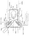
- FIG. 12 is a diagram for simply explaining a DPP type EUV light source device described in Patent Document 2 (Japanese Patent Publication No. 2007-505460).
- the EUV light source apparatus has a chamber 1 that is a discharge vessel.
- a discharge unit 1 a that houses a pair of disc-shaped discharge electrodes 2 a and 2 b, and an EUV collector that houses a foil trap 5, an EUV collector mirror that is a condensing optical means, and the like.
- Reference numeral 1c denotes a gas exhaust unit for exhausting the discharge unit 1a and the EUV condensing unit 1b to make the chamber 1 in a vacuum state.
- Reference numerals 2a and 2b are disk-shaped electrodes. The electrodes 2a and 2b are separated from each other by a predetermined interval, and rotate around the reference numerals 16c and 16d as the rotation motors 16a and 16b rotate, respectively.
- Reference numeral 14 denotes a high-temperature plasma raw material that emits EUV light having a wavelength of 13.5 nm.
- the high-temperature plasma raw material 14 is heated molten metal, for example, liquid tin (Sn), and is accommodated in the containers 15a and 15b.
- the electrodes 2a and 2b are arranged so that a part of the electrodes 2a and 2b is immersed in the containers 15a and 15b that contain the high-temperature plasma raw material 14.
- the liquid high-temperature plasma raw material 14 placed on the surfaces of the electrodes 2a and 2b is transported to the discharge space as the electrodes 2a and 2b rotate.
- the high temperature plasma raw material 14 transported to the discharge space is irradiated with laser light 17 from a laser source 17a.
- the high temperature plasma raw material 14 irradiated with the laser beam 17 is vaporized.
- the high-temperature plasma raw material 14 is vaporized by the irradiation of the laser beam 17, whereby a pulse discharge is started between the electrodes 2a and 2b.
- a plasma P is formed by the high temperature plasma raw material 14.
- the EUV light radiated from the high temperature plasma P is collected by the EUV collector mirror 9 at a condensing point (also referred to as an intermediate condensing point) f of the condensing mirror 9, and is emitted from the EUV light extraction unit 8 to the EUV light source device
- the light enters the exposure device 40 indicated by the connected dotted line.
- the EUV collector mirror 9 described above is an oblique incidence type collector mirror, and generally has a structure in which a plurality of thin concave mirrors are arranged in a nested manner with high accuracy.
- the shape of the reflecting surface of each concave mirror is, for example, a spheroidal shape, a rotating paraboloid shape, or a Walter shape, and each concave mirror is a rotating body shape.
- the Walter shape is a concave shape in which the light incident surface is composed of a rotation hyperboloid and a rotation ellipsoid, or a rotation hyperboloid and a rotation paraboloid in order from the light incidence side.
- the EUV collector mirror 9 includes a plurality of concave mirrors each having a reflecting surface having a spheroidal shape, a Walter shape, or the like, each having a rotating body shape having a different diameter. These concave mirrors constituting the EUV collector mirror are arranged on the same axis so that the rotation center axes are overlapped so that the focal positions substantially coincide with each other. By arranging the concave mirrors in a nested manner with high accuracy in this way, the EUV collector mirror can reflect EUV light with an oblique incident angle of 0 ° to 25 ° well and collect it at a single point. Composed.
- LDP Laser Assisted Gas Discharge Produced Plasma
- FIG. 13 is a diagram for simply explaining an LPP type EUV light source apparatus.
- the LPP type EUV light source apparatus has a light source chamber 1.
- the light source chamber 1 is provided with a raw material supply unit 10 and a raw material supply nozzle 20 for supplying a raw material (high temperature plasma raw material) that is an EUV radiation species. From the raw material supply nozzle 20, for example, droplet-shaped tin (Sn) is released as a raw material.
- the inside of the light source chamber 1 is maintained in a vacuum state by a gas exhaust unit 1c constituted by a vacuum pump or the like.
- a laser beam (laser beam) 22 from an excitation laser beam generator 21 which is a laser beam irradiation unit is introduced into the chamber 1 through a laser beam incident window 23 while being collected by a laser beam focusing unit 24.
- the raw material (for example, droplet-shaped tin) emitted from the raw material supply nozzle 20 is irradiated through a laser beam passage hole 25 provided at a substantially central portion of the EUV collector mirror 9.
- the excitation laser beam generation device 21 used here is, for example, a pulse laser device with a repetition frequency of several kHz, and a carbon dioxide (CO 2 ) laser, a YAG laser, or the like is used.
- the raw material supplied from the raw material supply nozzle 20 is heated and excited by irradiation with the laser light 22 to become high temperature plasma, and EUV light is emitted from this high temperature plasma.
- the emitted EUV light is reflected by the EUV collector mirror 9 toward the EUV light extraction unit 8, is collected at the condensing point (intermediate condensing point) of the EUV collector mirror 9, and is emitted from the EUV light extraction unit 8.
- the light is emitted and enters the exposure device 40 indicated by a dotted line connected to the EUV light source device.
- the EUV collector mirror 9 is a spherical reflecting mirror coated with, for example, a multilayer film of molybdenum and silicon.
- the laser light 22 for generating high temperature plasma may reach the EUV light extraction unit 8 as stray light. Therefore, a spectral purity filter (not shown) that transmits EUV light and does not transmit laser light 22 may be disposed in front of the EUV light extraction unit 8 (on the high-temperature plasma side).
- a foil trap 5 is installed between the discharge unit 1a and the EUV collector mirror 9 accommodated in the EUV light collector 1b in order to prevent damage to the EUV collector mirror 9. .
- the foil trap 5 functions to capture debris as described above and allow only EUV light to pass through. Examples of foil traps are shown in Patent Document 3 (Japanese Patent Publication No. 2002-504746), Patent Document 4 (Japanese Patent Publication No. 2004-214656), and Patent Document 5 (International Publication No. 2009/144609). Document 4 describes it as a “foil trap”.
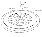
- FIG. 14 shows a schematic configuration of a foil trap as disclosed in Patent Document 3.
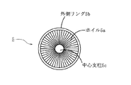
- the foil trap 5 is composed of a plurality of thin films (foil) or thin flat plates (plates) (hereinafter referred to as radial centers) that are radially arranged around the central axis of the foil trap 5 (in FIG. 14, coincident with the optical axis of EUV light).
- the thin film and the flat plate are collectively referred to as “foil 5a”), and concentrically arranged central struts 5c that support the plurality of foils 5a and an outer ring 5b that is a ring-shaped support.
- the foil 5a is arranged and supported so that its plane is parallel to the optical axis of the EUV light.
- the foil trap 5 when the foil trap 5 is viewed from the extreme ultraviolet light source (high temperature plasma) side, only the thickness of the foil 5a can be seen except for the support portions of the central support column 5c and the outer ring 5b. Therefore, most of the EUV light from the high temperature plasma P can pass through the foil trap 5.
- extreme ultraviolet light source high temperature plasma
- the plurality of foils 5a of the foil trap 5 function to increase the pressure by decreasing the conductance of the portion by finely dividing the arranged space. Therefore, the speed of debris from the high temperature plasma P decreases because the collision probability increases in a region where the pressure is increased by the foil trap 5. Some debris with reduced velocity is captured by the foil or foil support.
- light on the optical axis (light emitted from the high temperature plasma P at an angle of 0 ° (radiation angle is 0 °)) or the innermost part of the EUV collector mirror is used.
- the central support column 5c is generally shaped like a cone because it has a shape that shields light having a minimum incident angle determined from the configuration of the EUV collector mirror. Therefore, hereinafter, the central column 5c is also referred to as a cone.
- the foil trap 5 is arrange
- FIG. 15 shows a schematic configuration.
- the foil trap 4 closer to the high temperature plasma P has a function of rotating.
- the foil trap 4 having the rotation function is also referred to as a rotary foil trap
- the non-rotating fixed foil trap is also referred to as a fixed foil trap.
- the central column 4 c is connected coaxially with the rotation shaft of a rotation drive mechanism (not shown). When the rotary shaft of the rotary drive mechanism rotates, the rotary foil trap 4 rotates around the rotary shaft of the cone 4c.
- the rotary foil trap 4 captures debris flying from the plasma by rotating a plurality of foils 4a around the rotation axis of the central column 4c. For example, debris caused by Sn, which is a high-temperature plasma raw material, is captured by each foil 4a of the rotary foil trap 4, or deflected so that the traveling direction is different from the EUV mirror side. That is, accumulation of debris on each concave mirror of the EUV collector mirror 9 is suppressed by using the rotary foil trap 4.
- the fixed foil trap 5 captures high-speed debris that could not be captured by the rotary foil trap 4. Since the debris collision probability increases in the region where the pressure is increased by the fixed foil trap 5, the speed of the debris moving at a high speed decreases. Some debris with reduced speed is captured by the foil 5a or the foil support. That is, sputtering by high-speed debris of each concave mirror of the EUV collector mirror 9 is suppressed by using a fixed foil trap.
- the above-described foil trap is often used mainly in EUV light source devices of the DPP method and the LDP method.
- the collision direction to the EUV collector mirror is controlled by controlling the debris traveling direction by a magnetic field, or the debris adhering to the EUV collector mirror is removed by a cleaning gas such as hydrogen gas. is doing.
- the foil trap 5 as described above may be disposed between the high temperature plasma P and the EUV collector mirror 9. That is, the foil trap can be employed not only in a DPP or LDP EUV light source device but also in an LPP EUV light source device.
- the stable supply refers to supplying EUV light in a state where the decrease and fluctuation of the EUV light source output with time are suppressed.
- EUV light is irradiated on the mask blank to detect scattered light from the mask blank. Therefore, in order to reduce the measurement error, it is desirable that the output of EUV light supplied from the EUV light source is as small as possible in terms of output reduction and fluctuation.
- One of the causes of a decrease in the EUV light output emitted from the EUV light source is a decrease in EUV transmittance in a foil trap or an EUV collector mirror constituting the debris trap.
- debris caused by Sn generated from high-temperature plasma obtains large kinetic energy through plasma contraction and expansion processes.
- Such debris caused by Sn is ions or neutral atoms that move at high speed, and collides with the foil trap foil before reaching the EUV collector mirror, and part of the debris adheres to and accumulates on the foil trap foil. To do.
- a part of the gap between the foil traps becomes narrow, and as a result, the EUV transmittance with respect to the foil trap decreases.
- the foil trap (in the example shown in FIG. 15, the rotary foil trap 4) disposed to face the high temperature plasma is heated by the high temperature plasma.
- the debris as described above is also heated by colliding with the foil trap. That is, the heat load received by the foil trap is high. For this reason, a part of the foil constituting the foil trap is deformed, and the EUV transmittance with respect to the foil trap decreases with this deformation. Further, it is known that a high melting point material such as molybdenum constituting the foil becomes brittle as the recrystallization proceeds when the recrystallization temperature is exceeded. Depending on the degree of the above-mentioned heat load, the temperature of a part of the foil constituting the foil trap may be higher than the recrystallization temperature, and the recrystallization of the foil may progress and become brittle and break.
- some of the debris may reach the EUV collector mirror without being captured by the foil trap.
- Sn neutral atoms may adhere to and deposit on the reflective surface of the EUV collector mirror.
- the irradiated EUV light is absorbed and the EUV light is hardly reflected.
- Sn fast ions may scrape part of the reflective surface of the EUV collector mirror.
- the present invention has been made in view of the above circumstances, and a first object thereof is to provide a light source device capable of suppressing a decrease in light transmittance caused by debris in a debris trap. It is in.
- the second object of the present invention is to suppress a decrease in reflectivity in the condensing mirror, which occurs when debris caused by the high temperature plasma raw material released from the high temperature plasma moves at high speed and reaches the condensing mirror. It is in providing the light source device which can be performed.
- a shielding member having an opening for reducing the solid angle of light emitted from the high temperature plasma is interposed between the debris trap (foil trap) and the high temperature plasma P.
- the aperture member may be made of a material having high heat resistance.
- the light that has passed through the opening of the shielding member is irradiated to a part of the opening on the high temperature plasma side of the fixed foil trap, and the debris (Sn) that adheres to and accumulates on the foil of the foil trap constituting the debris trap.
- the amount is reduced, and the occurrence of thermal deformation of the foil due to heat input from the high temperature plasma P is also suppressed.
- a drive mechanism for driving the foil trap constituting the debris trap is provided, and the foil trap is driven so that the debris adhering portion of the foil trap is removed from the position facing the opening of the shielding member. Configured to do. As a result, a region on the foil trap where the debris is not attached or has a relatively small degree of adhesion can be opposed to the opening of the shielding member, and a decrease in light transmittance in the foil trap is suppressed. be able to.
- a drive mechanism is provided in the condensing mirror that collects the light emitted from the high-temperature plasma, and the condensing mirror is driven so that the debris adhering portion of the condensing mirror deviates from the position facing the opening of the shielding member. You may make it do.
- the light source device As a result, it is possible to reduce the decrease in the light transmittance of the condensing mirror, and the light source device as a whole suppresses the decrease in the light transmittance due to adhesion of debris, etc., and is stable from the light source device over a long period of time. Light can be output.
- a light source device including a container, a debris trap that captures at least part of debris from plasma that is generated in the container and emits light, and a condensing mirror that is disposed on the light emission side of the debris trap
- a shielding member having an opening for limiting a solid angle of the light so that an irradiation region of light emitted from the plasma is smaller than an opening on the plasma side of the debris trap between the plasma and the debris trap.
- the debris trap is provided with a drive mechanism for driving the debris trap so that the debris adhering portion of the debris trap is removed from the position facing the opening.
- the debris trap includes a plurality of radially extending foils, and includes at least one foil trap that passes the light but captures debris from the plasma.
- the driving operation of the foil trap may be a rotating operation.
- the debris trap includes a plurality of foils arranged substantially in parallel at a certain interval, and the foil trap through which the light passes but captures debris from the plasma. At least one of the foil trap driving operations may be a linear motion operation.
- the condensing mirror includes a drive mechanism that drives the condensing mirror so that a debris adhesion portion of the condensing mirror is removed from a position facing the opening.
- the condensing mirror is a grazing incidence condensing mirror having a structure in which a plurality of rotating body-shaped concave mirrors are arranged in a nested manner.
- the driving operation may be a rotation operation.
- the condensing mirror includes a region where EUV is reflected from a grazing incidence condensing mirror having a structure in which a plurality of rotating body-shaped concave mirrors are arranged in a nested manner.
- a plurality of collecting mirror section aggregates obtained by cutting out a plurality of sections are arranged in series, and the driving operation of the EUV focusing mirror may be a linear operation.
- the shielding member may be made of molybdenum or tungsten.
- the following effects can be obtained. (1) Since a shielding member having an opening that restricts the solid angle of light emitted from the plasma is arranged between the plasma and the debris trap, the amount of debris that adheres to and accumulates on the foil of the foil trap is reduced. The occurrence of thermal deformation of the foil due to heat input from the high temperature plasma can be suppressed. In addition, since the debris trap is driven so that the debris adhering portion of the debris trap deviates from the position facing the opening, the decrease in light transmittance in the foil trap due to the debris adhesion is suppressed (or recovered). ), The service life of the foil trap can be extended, and a stable light output can be obtained over a long period of time.
- the condensing mirror for condensing the light from the plasma is provided with a drive mechanism for driving the condensing mirror so that the debris adhering portion of the condensing mirror deviates from the position facing the opening. It is possible to suppress (or recover) the decrease in the reflectance of light in the condensing mirror due to the adhesion of the light, to prolong the service life of the condensing mirror and to obtain a stable light output over a long period of time. it can. In particular, it is possible to suppress (or recover) a decrease in light reflectivity in the condensing mirror caused by debris adhesion while maintaining the pressure in the chamber at a low pressure state (vacuum state). It is possible to obtain the same effect as exchanging the optical mirror, and it is possible to significantly reduce the downtime of the light source device associated with the conventional exchanging of the condensing mirror.
- the shielding member disposed between the plasma and the debris trap is made of a high heat-resistant material such as molybdenum or tungsten, the deterioration of the shielding member disposed near the high temperature plasma and receiving a large thermal load is reduced. be able to.
- the shielding member is made of a conductive metal, the shielding member can have the same potential as the debris trap and the chamber, and the occurrence of discharge in the chamber can be prevented.
- FIG. 1A is a diagram showing a first embodiment of a light source device of the present invention.
- FIG. 1B is a diagram showing a first embodiment of the light source device of the present invention.
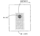
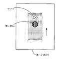
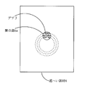
- FIG. 2A is a view of the rotary fixed foil trap seen through the opening of the shielding member in the light source device of FIG. 1A.
- FIG. 2B is a view of the rotary fixed foil trap seen through the opening of the shielding member in the light source device of FIG. 1A.
- FIG. 2C is a view of the rotation type fixed foil trap seen through the opening of the shielding member in the light source device of FIG. 1A.
- FIG. 2D is a view of the rotary fixed foil trap seen through the opening of the shielding member in the light source device of FIG. 1A.
- FIG. 1A is a diagram showing a first embodiment of a light source device of the present invention.
- FIG. 1B is a diagram showing a first embodiment of the light source device of the present invention.
- FIG. 2A
- FIG. 3A is a view showing a second embodiment of the present invention using a direct-acting fixed foil trap.
- FIG. 3B is a view showing a second embodiment of the present invention using a direct-acting fixed foil trap.
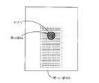
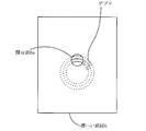
- 4A is a view of the direct-acting fixed foil trap seen through the opening of the shielding member in the light source device of FIG. 3A.
- 4B is a view of the direct-acting fixed foil trap seen through the opening of the shielding member in the light source device of FIG. 3A.
- 4C is a view of the direct-acting fixed foil trap seen through the opening of the shielding member in the light source device of FIG. 3A.
- 4D is a view of the direct-acting fixed foil trap seen through the opening of the shielding member in the light source device of FIG.
- FIG. 5 is a view showing a third embodiment of the present invention provided with a rotary fixed foil trap and a rotary foil trap.
- FIG. 6 is a view showing a fourth embodiment of the present invention in which only a rotary foil trap is provided as a debris trap.
- FIG. 7A is a diagram showing a fifth embodiment that employs a rotating EUV collector mirror.
- FIG. 7B is a diagram showing a fifth embodiment in which a rotating EUV collector mirror is employed.
- FIG. 8A is a view of the rotary EUV collector mirror viewed through the opening of the shielding member in the light source device of FIG. 7A.
- FIG. 8B is a view of the rotary EUV collector mirror viewed through the opening of the shielding member in the light source device of FIG. 7A.
- FIG. 8C is a view of the rotary EUV collector mirror viewed through the opening of the shielding member in the light source device of FIG. 7A.
- FIG. 8D is a view of the rotary EUV collector mirror viewed through the opening of the shielding member in the light source device of FIG. 7A.
- FIG. 9 is a view showing a sixth embodiment of the present invention which employs a rotating EUV collector mirror and is provided with a rotating fixed foil trap and a rotating foil trap.
- FIG. 10A is a diagram showing a seventh embodiment of the present invention using a direct-acting EUV collector mirror.
- FIG. 10B is a diagram showing a seventh embodiment of the present invention using a direct-acting EUV collector mirror.
- FIG. 10A is a diagram showing a seventh embodiment of the present invention using a direct-acting EUV collector mirror.
- FIG. 11A is a view of the direct-acting EUV collector mirror viewed from the opening of the shielding member in the light source device of FIG. 10A.
- FIG. 11B is a view of the direct-acting EUV collector mirror viewed from the opening of the shielding member in the light source device of FIG. 10A.
- FIG. 11C is a view of the direct-acting EUV collector mirror viewed from the opening of the shielding member in the light source device of FIG. 10A.
- FIG. 11D is a view of the direct-acting EUV collector mirror viewed from the opening of the shielding member in the light source device of FIG. 10A.
- FIG. 12 is a diagram for simply explaining a DPP type EUV light source apparatus.
- FIG. 12 is a diagram for simply explaining a DPP type EUV light source apparatus.
- FIG. 13 is a diagram for simply explaining an LPP type EUV light source apparatus.
- FIG. 14 is a diagram showing a configuration example of a foil trap.
- FIG. 15 is a diagram showing a schematic configuration of a light source device in which two foil traps are provided in series and one of the foil traps is rotated.
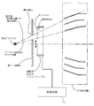
- FIG. 1A and 1B show a first embodiment of an EUV light source apparatus for mask blank inspection according to the present invention.
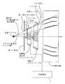
- FIG. 1A is a cross-sectional view (a cross-sectional view cut along the optical axis of EUV light) showing the arrangement of the shielding member 6, the rotary fixed foil trap 5, and the EUV collector mirror 9 in the light source device of this embodiment.
- FIG. 1B shows the rotation type fixed foil trap 5 as viewed from the shielding member 6 side. As shown in FIG.
- a shielding member 6 having an opening 6a is disposed between the high temperature plasma P and a rotary fixed foil trap 5 shown in FIG.
- An EUV collector mirror that condenses EUV light is provided at the subsequent stage of the type foil trap 5.
- EUV light emitted from the EUV light source device irradiates a relatively large irradiation area on a workpiece (wafer). Therefore, the etendue of the EUV light (the product of the size of the high temperature plasma P and the solid angle of extraction of EUV light from the plasma) also increases to some extent.
- EUV light emitted from the EUV light source device irradiates a considerably small irradiation area of a work (on the mask blank) as compared with that used as an exposure light source. Is done. That is, the EUV light emitted from the EUV light source device used as the mask blank inspection light source can make the etendue relatively small. Therefore, the EUV irradiation light irradiated onto the mask blank has a small etendue and thus has high brightness and sharp light.
- the EUV light source device for mask blank inspection pays attention to the characteristic that the etendue of the EUV light emitted from the EUV light source device can be reduced, and the solid angle of the EUV light emitted from the high temperature plasma P.
- the aperture member (shielding member 6) having an opening 6a for reducing the solid angle of the EUV light extracted from the high temperature plasma P is restricted between the debris trap (fixed foil trap 5) and the high temperature plasma P.
- the aperture member (shielding member 6) is made of a material having high heat resistance.
- the shielding member 6 having an opening 6a for extracting EUV light having a predetermined solid angle is provided between the high temperature plasma P and the debris trap.
- the opening 6a of the shielding member 6 limits the solid angle of the light so that the irradiation area of the light emitted from the plasma P is smaller than the size of the opening of the foil trap 5 on the plasma side.
- the EUV light that has passed through the opening 6a of the shielding member 6 is irradiated to a part of the opening on the high temperature plasma P side of the fixed foil trap 5 as shown in FIG. 1A.
- a debris trap having a fixed foil trap 5 and a shielding member 6 having an opening 6 a between the debris trap and the high temperature plasma P are provided.
- the shielding member 6 is made of a high melting point material such as molybdenum (Mo) or tungsten (W), for example.
- Mo molybdenum
- W tungsten
- the shielding member 6 Since the debris reducing device main body and the chamber (vacuum vessel) in which these are housed are normally grounded and at a ground potential, the shielding member 6 is electrically connected to the debris reducing device main body and the chamber in which these are housed and grounded. By setting the potential, they can be set to the same potential, and discharge between them can be prevented. For the above reasons, it is desirable that the shielding member 6 is composed of a conductive member.
- the fixed foil trap 5 is similar to the one shown in FIG. 14 described above.
- the foil 5a is arranged radially in the radial direction, and the concentric center arranged to support the plurality of foils 5a. It is comprised from the support
- the shielding member 6 as shown in FIGS.
- the temperature of the shielding member 6 is adjusted to a melting point of 230 ° C. or higher of tin (Sn), which is a high-temperature plasma P raw material, by a temperature control mechanism (not shown) if necessary.
- tin tin
- the temperature of the shielding member 6 is preferably adjusted to be equal to or lower than the boiling point of Sn.
- the fixed foil trap 5 constituting the debris trap is configured to be rotatable as described above. That is, the fixed foil trap 5 of this embodiment is provided with a drive mechanism 7 and is rotated about the rotation axis by the drive mechanism 7 (in such a fixed foil trap, it is configured to be rotatable. Here, this is referred to as a rotation-type fixed foil trap 5).
- the rotary foil trap 4 shown in FIG. 15 captures debris flying from the plasma P by a rotating operation, and rotates at a predetermined rotational speed that effectively captures debris flying from the plasma.
- the rotation type fixed foil trap 5 shown in FIGS. 1A and 1B rotates so that the debris adhering portion is removed from the position facing the opening 6a. If attached, the foil trap 5 is rotated stepwise. Instead of rotating in a stepped manner, the debris adhering portion may be rotated relatively slowly so as to deviate from the position facing the opening 6a. In this case, the debris flying through the opening 6a of the shielding member will be dispersed and attached to the entire foil 5a of the foil trap 5, so that a decrease in light transmittance can be suppressed. In this case, the foil trap 5 is always moving. In order to clarify the difference from the rotary foil trap 4, the foil trap rotating in this way is also a rotary fixed foil. This is a trap.
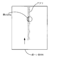
- FIG. 2A to 2D are views of the rotating fixed foil trap 5 of FIG. 1A through the opening 6a of the shielding member 6 when the foil trap 5 is rotated stepwise.
- the shielding member 6 is provided as described above. Therefore, as shown in FIG. 2A, the EUV light beam passes through a part of the fixed foil trap 5.
- debris (Sn ions and neutral Sn atoms moving at high speed) emitted from the high temperature plasma P is expected to reach only a part of the fixed foil trap 5, the fixed foil trap. Even if debris (Sn) adheres to 5, the Sn adhesion region becomes a partial region of the fixed foil trap 5 as shown in FIG. 2B.
- the rotary type fixed foil trap 5 that is configured so that the fixed type foil trap 5 can rotate, the debris of the rotary type fixed foil trap 5 is deviated from the position facing the opening of the shielding member 6.
- the attached area can be moved.
- the rotary fixed foil trap 5 is rotated by the driving means (not shown) until the debris adhesion region is not visible from the position facing the opening of the shielding member 6, and then the illustration is shown.
- the rotation type fixed foil trap 5 is fixed by the omitted fixing means.
- the rotating type fixed foil trap 5 is rotated and fixed by the fixing means.
- the solid angle of EUV light emitted from the high temperature plasma P can be limited by the opening of the shielding member 6.
- the fixed-type foil trap 5 is configured so that the fixed-type foil trap 5 can be rotated, and the fixed-type foil trap 5 can be rotated according to the degree of debris adhering to the fixed-type foil trap 5.
- a shielding member having an opening is disposed between the high temperature plasma and the debris trap (fixed foil trap).
- a rotating type fixed foil trap is used in which a fixed type foil trap having a plurality of foils extending radially from the main shaft (center support column) is configured to be rotatable.
- the configuration of the fixed foil trap is not limited to the above.
- the second embodiment shows a modification of the fixed foil trap in the first embodiment.
- 3A and 3B show a second embodiment of the present invention, and FIG.
- FIG. 3A shows the arrangement of the shielding member 6, the direct-acting fixed foil trap 51, and the EUV collector mirror 9 in the light source device of the present embodiment.
- FIG. 3B shows the fixed foil trap of the present embodiment viewed from the shielding member 6 side.
- FIG. 3B is a sectional view (cross-sectional view cut along the optical axis of EUV light).
- the fixed foil trap 51 provided between the shielding member 6 having the opening 6a and the EUV collector mirror 9 includes a plurality of foils 51a as shown in FIG. 3B.
- This is a fixed foil trap 51 that is arranged substantially in parallel at a predetermined interval (for example, at equal intervals).
- the fixed foil trap 51 in the second embodiment employs a structure in which a plurality of foils 51a are fixed inside a rectangular fixed frame 51b so as to be arranged substantially in parallel with a predetermined interval. Yes.
- FIG. 4A to 4D are views of the direct-acting fixed foil trap 51 viewed through the opening 6a of the shielding member 6 when the foil trap is linearly moved.
- the solid angle of the EUV light emitted from the high-temperature plasma P can be reduced. Therefore, as shown in FIG. It will pass through some area of.
- debris (Sn ions and neutral Sn atoms moving at high speed) emitted from the high temperature plasma P is expected to reach only a part of the fixed foil trap 51, the fixed foil trap Even if debris (Sn) adheres to 51, the Sn adhesion region becomes a partial region of the fixed foil trap 51 as shown in FIG. 4B.
- the fixed foil trap 51 of the present embodiment is configured to be movable in a straight line. That is, the fixed foil trap 51 of the present embodiment is provided with a drive mechanism 71 and moves linearly by the drive mechanism 71 (this operation is referred to as a linear movement here, and the fixed foil trap of the present embodiment The trap is referred to as a direct-acting fixed foil trap 51). Then, by adopting the direct-acting fixed foil trap 51 in which the fixed-type foil trap 51 having such a structure is configured to be capable of linear motion, the direct-acting fixed foil can be moved from the position facing the opening 6a of the shielding member 6. It becomes possible to move the area where the debris of the trap 51 adheres. That is, as shown in FIG.
- the linear motion type fixed foil trap 51 is linearly moved by the driving means 71 until the debris adhesion region is not visible from the position facing the opening 6a of the shielding member 6, and then the illustration is made.
- the direct-acting fixed foil trap 51 is fixed by the omitted fixing means.
- the direct acting fixing is performed until the region where the debris is attached cannot be seen from the opening 6a.
- the type foil trap 51 is linearly moved by the driving means 71 and fixed by the fixing means.
- a direct-acting fixed foil trap 51 in which a fixed foil trap, in which a plurality of foils 51a are arranged substantially in parallel at predetermined intervals (for example, equal intervals), is configured so as to be linearly movable is adopted.
- the direct-acting fixed foil trap 51 is directly moved and fixed, so that EUV in the direct-acting fixed foil trap 51 caused by debris adhesion
- the decrease in light transmittance can be recovered.
- the service life of the direct-acting fixed foil trap 51 can be extended, and EUV light can be stably supplied to the inspection optical system side of the mask blank inspection apparatus over a long period of time. Is possible.
- the linear motion / fixing operation of the linear motion type fixed foil trap 51 can be performed while the pressure in the chamber is maintained in a low pressure state (vacuum state).
- the downtime of the EUV light source device associated with the replacement of the fixed foil trap 51 can be greatly reduced.
- the direction in which each foil 51a of the direct-acting fixed foil trap 51 extends coincides with the direct-acting direction of the direct-acting fixed foil trap 51. There is no need to match.
- the direction in which each foil 51 a of the direct acting fixed foil trap 51 extends may be substantially perpendicular to the direct acting direction of the direct acting fixed foil trap 51.
- the direct acting fixed foil trap 51 is moved stepwise each time debris adheres to a certain extent, but it is similar to the rotating fixed foil trap 5 of the first embodiment.
- the direct-acting fixed foil trap 51 may be moved slowly and continuously in a straight line.
- FIG. 5 shows an embodiment in which a rotary fixed foil trap 5 and a rotary foil trap 4 are provided between the shielding member 6 and the EUV collector mirror 9.
- the rotary fixed foil trap 5 includes a foil 5a arranged radially in the radial direction, a central column 5c and a ring arranged concentrically to support the plurality of foils 5a.
- the stationary foil trap 5 is provided with a drive mechanism 7, and the drive mechanism 7 allows the debris adhering portion to be removed from the position facing the opening 6 a of the shielding member 6. To turn.
- Debris flying from the high temperature plasma P through the opening 6a of the shielding member is captured by the rotating fixed foil trap 5 as described above, but is not captured by the rotating fixed foil trap 5. Is captured or deflected by a rotary foil trap 4 provided in the subsequent stage.
- the rotary foil trap 4 captures debris flying from the plasma P when the plurality of foils 4a rotate around the rotation axis of the central support column 4c, and is Sn that is a high temperature plasma raw material.
- the debris resulting from is trapped by each foil 4a of the rotary foil trap 4 or deflected so that the traveling direction is different from the EUV collector mirror 9 side.
- the rotation type fixed foil trap 5 rotates so that the debris adhering portion is disengaged from the position facing the opening 6a of the shielding member 6, so that the decrease in EUV light transmittance is suppressed (recovered). And the service life can be extended. Further, since the rotary foil trap 4 is always rotating, the debris flying through the opening 6a of the shielding member is dispersed and attached to the entire foil 4a of the foil trap 4, and the rotary fixed foil trap 5 Similarly to the above, a decrease in EUV light transmittance is suppressed, and the service life can be extended.
- the rotating type fixed foil trap 5 and the rotating type foil trap 4 shown in FIGS. 1A and 1B are used has been described.
- the direct acting fixed type shown in FIGS. 3A and 3B is used.
- the rotary foil trap 4 may be added to the embodiment using the foil trap 51.
- the rotating fixed foil trap 5 is interposed through the opening 6 a of the shielding member 6.
- the rotary foil trap 4 is disposed so as to face the high temperature plasma P through the opening 6 a of the shielding member 6, and the rotary fixed foil trap 5 is disposed on the light emitting side of the rotary foil trap 4. You may comprise.
- the rotary fixed foil trap 5 may be disposed on both the light incident side and the light emitting side of the rotary foil trap 4.
- the rotary foil trap 4 may be added to the embodiment using the direct acting fixed foil trap 51 shown in FIG. 3B.
- the rotary foil trap 4 Since the rotary foil trap 4 is always rotating, as described above, the debris flying through the opening 6a of the shielding member 6 is dispersed and adhered to the entire foil 4a of the foil trap 4, and is fixed to the rotary type. As with the foil trap 5, a decrease in EUV light transmittance is suppressed. Therefore, when the amount of debris (Sn) is relatively small, even if only the rotary foil trap 4 is provided as shown in FIG. 6, the service life of the foil trap 4 can be extended. For a long period of time, it becomes possible to stably supply EUV light to the inspection optical system side of the mask blank inspection apparatus.
- the solid angle of the EUV light emitted from the high temperature plasma P is limited to restrict the solid angle of the EUV light.
- An aperture member having an opening for reducing the solid angle of EUV light taken out from the lens is disposed between the debris trap and the high temperature plasma P, and the aperture member is made of a material having high heat resistance.
- the EUV light flux passes through a partial region of the debris trap (the fixed foil trap 5 and the rotary foil trap 4) and is similarly emitted from the high temperature plasma P.
- Debris Sn ions and neutral Sn atoms moving at high speed
- the debris (Sn) adhesion region also becomes a part of the debris trap.
- the service life of the fixed foil trap 5 and the rotary foil trap 4 is increased. That is, the fixed foil trap 5 is rotated and moved linearly, or the rotary foil trap 4 is used to debris adhesion regions of the fixed foil trap 5 and the rotary foil trap 4 from the position facing the opening of the shielding member 6. I moved it.
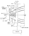
- FIG. 7A is a cross-sectional view (a cross-sectional view cut along the optical axis of EUV light) showing the arrangement of the shielding member 6, the rotary foil trap 4, and the EUV collector mirror 91 in the light source device of the present embodiment.
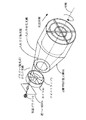
- 7B is a perspective view showing the arrangement of the high temperature plasma, the rotary foil trap 4, the EUV collector mirror 91, and the like.
- the EUV light reflected by the oblique-incidence type EUV collector mirror 91 having a structure in which the concave mirrors of the rotating body are arranged in a nested manner with high precision is reflected only in a part of the EUV collector mirror reflecting surface. By utilizing this, the service life of the EUV collector mirror 91 is extended.
- a rotation type EUV collector mirror 91 is employed in which the EUV collector mirror 9 having the above structure is configured to be rotatable. That is, the EUV collector mirror 91 is provided with a drive mechanism 79, and the drive mechanism 79 rotates the EUV collector mirror 91 about its rotation axis (optical axis).
- the rotary foil trap 4 is used as a debris trap.
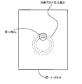
- FIGS. 8A to 8D are views of the rotary EUV collector mirror 91 as viewed from the opening 6a of the shielding member 6.
- FIG. 8A Note that the foil trap 4 is omitted in FIGS. 8A to 8D.
- the EUV light beam incident through the opening 6a of the shielding member 6 and the rotary foil trap 4 enters the rotary EUV collector mirror 91 and is reflected by a partial region of the reflection surface. Is done.
- debris Sn ions and neutral Sn atoms moving at high speed
- the region where the debris on the reflection surface of the rotation type EUV collector mirror 91 is attached is moved from the position facing the opening of the shielding member 6. Is possible. That is, as shown in FIG. 8C, the rotating EUV collector 91 is omitted from the position facing the opening of the shielding member 6 until the debris adhesion region is not visible (with the driving mechanism 79 in FIG. 7A). Then, the rotation type EUV collector mirror 91 is fixed by fixing means (not shown). Similarly, when debris adheres to some extent in the position shown in FIG. 8C in the rotating EUV collector mirror 91, as shown in FIG. The rotating EUV collector mirror 91 is rotated and fixed by the fixing means.
- the solid angle of EUV light emitted from the high temperature plasma P can be limited by the opening 6a of the shielding member 6.
- the rotation type EUV collector mirror 91 configured so that the EUV collector mirror 91 can be rotated is used, and the EUV collector mirror 91 rotates according to the degree of debris adhesion to the reflecting surface of the rotation type EUV collector mirror 91.
- the service life of the type EUV collector mirror 91 can be extended, and EUV light can be stably supplied to the inspection optical system side of the mask blank inspection apparatus over a long period of time.
- the rotary foil trap 4 is used as the debris trap, the debris flying through the opening 6a of the shielding member 6 is dispersed throughout the foil 4a of the foil trap 4 as described above. And the decrease in the transmittance of EUV light is suppressed.
- rotation / fixing operation of the rotation type EUV collector mirror 91 can be performed while maintaining the pressure in the chamber in a low pressure state (vacuum state). That is, it is possible to obtain an action equivalent to replacing the EUV collector mirror 9 with a new one having substantially no debris on the reflecting surface without breaking the vacuum. It is possible to greatly reduce the downtime of the EUV light source device accompanying the replacement of the condenser mirror 9.
- FIGS. 7A and 7B In the embodiment shown in FIGS. 7A and 7B, the case where the rotary foil trap 4 is provided between the shielding member 6 and the rotary EUV collector mirror 91 has been described.
- a rotating fixed foil trap 5 may be provided.
- FIG. 9 shows an embodiment in which a rotary fixed foil trap 5 and a rotary foil trap 4 are provided between the shielding member and the EUV collector mirror.
- FIG. 9 is a cross-sectional view (along the optical axis of EUV light) showing the arrangement of the shielding member 5, the rotary fixed foil trap 5, the rotary foil trap 4, and the EUV collector mirror 91 in the light source device of this embodiment. It is a cut sectional view).
- the rotary fixed foil trap 5 includes a foil 5a arranged radially in the radial direction, a central column 5c and a ring arranged concentrically to support the plurality of foils 5a.
- the stationary foil trap 5 is provided with a drive mechanism 7, and the drive mechanism 7 allows the debris adhering portion to be removed from the position facing the opening 6 a of the shielding member 6.
- the direct acting fixed foil trap 51 shown in FIG. 3 may be used. Debris flying from the high temperature plasma P through the opening 6a of the shielding member is captured by the rotating fixed foil trap 5 as described above with reference to FIG. The debris that has not been captured is captured by the rotary foil trap 4 provided at the subsequent stage, or deflected so that the traveling direction is different from the EUV collector 91 side.
- the debris that has passed through the rotary foil trap 4 reaches the rotary EUV collector mirror 91 provided at the subsequent stage.
- the debris since the debris has come through the opening 6a of the shielding member, it is expected to reach only a part of the reflecting surface of the rotary EUV collector mirror 91 as described above. Even if debris (Sn) adheres to the dynamic EUV collector mirror 91, it becomes a partial region of the reflecting surface. For this reason, the fall of the reflectance of EUV light is suppressed (recovered) by moving the region where the debris on the reflecting surface of the rotary EUV collector mirror 91 is attached from the position facing the opening of the shielding member 6. The service life can be extended.
- the rotary fixed foil trap 5 and the rotary foil trap 4 are provided as described above, so that debris reaching the rotary EUV collector mirror 91 can be reduced more effectively. it can.
- the rotating EUV collector mirror 91 since the rotating EUV collector mirror 91 is used, the EUV light reflected by the rotating EUV collector mirror 91 is moved by moving the region where the debris on the reflecting surface of the rotating EUV collector mirror 91 is attached. The decrease in rate can be suppressed (recovered), and the service life can be extended.
- the rotation type fixed foil trap 5 rotates so that the debris adhering portion is disengaged from the position facing the opening 6a of the shielding member 6, so that the decrease in EUV light transmittance is suppressed (recovered). And the service life can be extended. Further, since the rotary foil trap 4 is always rotating, the debris flying through the opening 6a of the shielding member is dispersed and attached to the entire foil 4a of the foil trap 4, and the rotary fixed foil trap 5 Similarly to the above, a decrease in EUV light transmittance is suppressed, and the service life can be extended.
- the rotary fixed foil trap 5 is disposed so as to face the high-temperature plasma P through the opening 6a of the shielding member 6, but as described above, the rotary foil The trap 4 may be disposed so as to face the high temperature plasma P through the opening 6 a of the shielding member 6, and the rotary fixed foil trap 5 may be disposed on the light emitting side of the rotary foil trap 4.
- the shielding member 6 having an opening is formed of a high temperature plasma P and a debris trap (fixed foil trap 5). And / or a rotating foil trap), and an oblique incidence type EUV collector mirror having a structure in which a plurality of thin concave rotating mirrors are arranged with high precision in a nested manner.
- a rotating type EUV collector mirror 91 configured to be rotatable is employed.
- the seventh embodiment shows a modification of the EUV collector mirror in the fifth and sixth embodiments.
- FIG. 10A and 10B show a seventh embodiment of the present invention
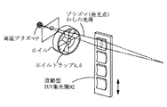
- FIG. 10A shows a shielding member 6 and a debris trap (rotary fixed foil trap 5, rotating foil trap 4) in the light source device of the present embodiment
- FIG. 10B is a perspective view showing the arrangement of the high-temperature plasma P, the debris trap, the direct-acting EUV collector mirror 92, and the like. In FIG. 10B, only one foil trap constituting the debris trap is shown for easy understanding.
- the oblique incidence type EUV light condensing structure in which the plurality of rotating body-shaped concave mirrors of the fifth and sixth embodiments are arranged in a nested manner.
- a plurality of sections including a portion where EUV light reaches the reflecting surface (region where EUV is reflected) are cut out to form an EUV collector mirror section assembly 92a, and the EUV collector mirror assembly 92a
- An EUV collector mirror 92 having a structure in which a plurality of these are arranged in series is employed.
- the EUV collector mirror 92 is provided with a drive mechanism 78.
- the drive mechanism 78 causes the EUV collector mirror 92 to move linearly in the arrangement direction of the EUV collector mirror assembly 92a (such as Here, the operation is referred to as a linear motion, and the EUV collector mirror of this embodiment is referred to as a direct-acting EUV collector mirror 92).
- each EUV collector mirror section 92a is composed of a plurality of collector mirror sections arranged in a nested manner, and a plurality of these sections are attached to the collector mirror section holder 92b.
- the EUV collector mirror 92 may be configured.
- FIGS. 11A to 11D are views of the direct-acting EUV collector mirror 92 viewed from the opening 6a of the shielding member 6.
- FIG. 11D the debris trap is omitted.
- the solid angle of EUV light emitted from the high temperature plasma P can be reduced, as shown in FIG. 11A, from the opening 6a of the shielding member 6 All incident EUV light fluxes are reflected by the reflecting surface of the segment (condenser mirror assembly) 92a of the direct-acting EUV collector mirror 92.
- the Sn attachment region has a plurality of EUVs constituting the EUV collector mirror 92 of the seventh embodiment. It is at least a part of the reflecting surface of the collector mirror section 92a.
- the direct-acting EUV condensing mirror 92 configured so that the EUV condensing mirror having such a structure can be moved linearly, the direct-acting EUV condensing mirror is positioned from the position facing the opening 6a of the shielding member 6. It is possible to move the area where 92 debris is attached. That is, as shown in FIG. 11C, the direct-acting EUV collector mirror 92 is moved from the position facing the opening 6a of the shielding member 6 until the EUV collector mirror section adjacent to the EUV collector mirror section 92a to which debris has adhered is exposed. After positioning by direct movement by the driving means 78, the direct-acting EUV collector mirror 92 is fixed by fixing means (not shown).
- a direct-acting EUV condensing mirror 92 in which an EUV condensing mirror having a structure in which a plurality of EUV condensing mirror segment aggregates are arranged in series is configured to be directly movable is employed.
- the direct-acting EUV condensing mirror 92 is linearly moved and fixed in accordance with the degree of debris adhering to the EUV condensing mirror section aggregate, thereby causing the direct-acting EUV condensing mirror resulting from the debris adhesion.
- the decrease in EUV light reflectance at 92 can be recovered.
- the service life of the direct-acting EUV collector mirror 92 can be extended, and the EUV light can be stably supplied to the inspection optical system side of the mask blank inspection apparatus for a long period of time. Is possible.
- the linear movement / fixing operation of such a direct-acting EUV collector mirror can be performed while maintaining the pressure in the chamber at a low pressure state (vacuum state). It becomes possible to significantly reduce the downtime of the EUV light source apparatus associated with the replacement of the EUV collector mirror 9 as in the prior art.
- the rotary foil trap 4 or the rotary fixed foil trap 5 and the rotary foil trap 4 are used.
- the rotary fixed foil trap is used. 5 or only the direct-acting fixed foil trap 51 may be provided.
Landscapes
- Physics & Mathematics (AREA)
- Engineering & Computer Science (AREA)
- Plasma & Fusion (AREA)
- Optics & Photonics (AREA)
- General Physics & Mathematics (AREA)
- Chemical & Material Sciences (AREA)
- Analytical Chemistry (AREA)
- Atmospheric Sciences (AREA)
- Health & Medical Sciences (AREA)
- Epidemiology (AREA)
- Public Health (AREA)
- Life Sciences & Earth Sciences (AREA)
- Environmental & Geological Engineering (AREA)
- General Engineering & Computer Science (AREA)
- Exposure And Positioning Against Photoresist Photosensitive Materials (AREA)
- Exposure Of Semiconductors, Excluding Electron Or Ion Beam Exposure (AREA)
- X-Ray Techniques (AREA)
Abstract
L'invention porte sur un dispositif de source de lumière qui réduit à un minimum des diminutions du facteur de réflexion d'un miroir de condensation ou du facteur de transmission d'un piège de débris en raison de débris. Dans ce dispositif, un élément de masquage (6) qui possède une ouverture (6a) est disposé à l'avant d'un piège à feuille fixe (5) afin de limiter l'angle solide sous-tendu par une lumière émise par un plasma à haute température (P). Le piège à feuille fixe (5) est également pourvu d'un mécanisme de pilotage (7) et est tourné à l'opposé d'un emplacement dans lequel une section du piège à feuille, auquel un débris est attaché, est tournée vers l'ouverture susmentionnée (6a). Ceci rend possible la réduction à un minimum (ou l'inversion) des diminutions du facteur de transmission en raison de débris attachés, ce qui mène à une durée de vie d'utilisation plus longue. Le piège à feuille peut également être un piège à feuille rotatif (4) qui piège des débris provenant du plasma par rotation. Un miroir de condensation EUV (9) peut également être tourné afin de réduire à un minimum des diminutions de facteur de réflexion en raison de débris attachés.
Priority Applications (1)
| Application Number | Priority Date | Filing Date | Title |
|---|---|---|---|
| US15/107,824 US9572240B2 (en) | 2013-12-25 | 2014-12-12 | Light source apparatus |
Applications Claiming Priority (2)
| Application Number | Priority Date | Filing Date | Title |
|---|---|---|---|
| JP2013-266669 | 2013-12-25 | ||
| JP2013266669A JP5983594B2 (ja) | 2013-12-25 | 2013-12-25 | 光源装置 |
Publications (1)
| Publication Number | Publication Date |
|---|---|
| WO2015098031A1 true WO2015098031A1 (fr) | 2015-07-02 |
Family
ID=53477937
Family Applications (1)
| Application Number | Title | Priority Date | Filing Date |
|---|---|---|---|
| PCT/JP2014/006223 Ceased WO2015098031A1 (fr) | 2013-12-25 | 2014-12-12 | Dispositif de source de lumière |
Country Status (3)
| Country | Link |
|---|---|
| US (1) | US9572240B2 (fr) |
| JP (1) | JP5983594B2 (fr) |
| WO (1) | WO2015098031A1 (fr) |
Families Citing this family (8)
| Publication number | Priority date | Publication date | Assignee | Title |
|---|---|---|---|---|
| KR102122484B1 (ko) * | 2012-11-15 | 2020-06-15 | 에이에스엠엘 네델란즈 비.브이. | 리소그래피를 위한 방법 및 방사선 소스 |
| US9870612B2 (en) * | 2016-06-06 | 2018-01-16 | Taiwan Semiconductor Manufacturing Co., Ltd. | Method for repairing a mask |
| WO2019003284A1 (fr) * | 2017-06-26 | 2019-01-03 | ギガフォトン株式会社 | Dispositif de génération de lumière ultraviolette extrême |
| KR102539528B1 (ko) * | 2020-06-12 | 2023-06-02 | 우시오덴키 가부시키가이샤 | 극단 자외광 광원 장치 |
| JP7468246B2 (ja) * | 2020-08-21 | 2024-04-16 | ウシオ電機株式会社 | 極端紫外光光源装置 |
| JP7347402B2 (ja) * | 2020-11-25 | 2023-09-20 | ウシオ電機株式会社 | 回転式ホイルトラップおよび光源装置 |
| JP7491245B2 (ja) * | 2021-03-11 | 2024-05-28 | ウシオ電機株式会社 | ホイルトラップ及びこれを備えた光源装置 |
| CN118002555A (zh) * | 2024-01-23 | 2024-05-10 | 上海大学 | 一种用于z箍缩放电等离子体源的碎屑清除装置及其应用 |
Citations (4)
| Publication number | Priority date | Publication date | Assignee | Title |
|---|---|---|---|---|
| JP2010232150A (ja) * | 2009-03-30 | 2010-10-14 | Ushio Inc | 極端紫外光光源装置 |
| JP2011515022A (ja) * | 2008-02-28 | 2011-05-12 | コーニンクレッカ フィリップス エレクトロニクス エヌ ヴィ | 回転フォイルトラップ及び駆動装置を持つデブリ低減装置 |
| JP2011187875A (ja) * | 2010-03-11 | 2011-09-22 | Ushio Inc | 集光鏡アッセンブリおよびこの集光鏡アッセンブリを用いた極端紫外光光源装置 |
| JP2013187098A (ja) * | 2012-03-09 | 2013-09-19 | Lasertec Corp | プラズマシールド装置及びプラズマ光源装置 |
Family Cites Families (6)
| Publication number | Priority date | Publication date | Assignee | Title |
|---|---|---|---|---|
| NL1008352C2 (nl) | 1998-02-19 | 1999-08-20 | Stichting Tech Wetenschapp | Inrichting, geschikt voor extreem ultraviolet lithografie, omvattende een stralingsbron en een verwerkingsorgaan voor het verwerken van de van de stralingsbron afkomstige straling, alsmede een filter voor het onderdrukken van ongewenste atomaire en microscopische deeltjes welke door een stralingsbron zijn uitgezonden. |
| JP3728495B2 (ja) | 2001-10-05 | 2005-12-21 | 独立行政法人産業技術総合研究所 | 多層膜マスク欠陥検査方法及び装置 |
| CN100476585C (zh) | 2002-12-23 | 2009-04-08 | Asml荷兰有限公司 | 具有可扩展薄片的杂质屏蔽 |
| DE10342239B4 (de) | 2003-09-11 | 2018-06-07 | Fraunhofer-Gesellschaft zur Förderung der angewandten Forschung e.V. | Verfahren und Vorrichtung zum Erzeugen von Extrem-Ultraviolettstrahlung oder weicher Röntgenstrahlung |
| WO2009144609A1 (fr) | 2008-05-28 | 2009-12-03 | Philips Intellectual Property & Standards Gmbh | Dispositif d’atténuation de débris |
| NL2003610A (en) | 2008-12-22 | 2010-06-23 | Asml Netherlands Bv | A lithographic apparatus, a radiation system, a device manufacturing method and a radiation generating method. |
-
2013
- 2013-12-25 JP JP2013266669A patent/JP5983594B2/ja active Active
-
2014
- 2014-12-12 WO PCT/JP2014/006223 patent/WO2015098031A1/fr not_active Ceased
- 2014-12-12 US US15/107,824 patent/US9572240B2/en active Active
Patent Citations (4)
| Publication number | Priority date | Publication date | Assignee | Title |
|---|---|---|---|---|
| JP2011515022A (ja) * | 2008-02-28 | 2011-05-12 | コーニンクレッカ フィリップス エレクトロニクス エヌ ヴィ | 回転フォイルトラップ及び駆動装置を持つデブリ低減装置 |
| JP2010232150A (ja) * | 2009-03-30 | 2010-10-14 | Ushio Inc | 極端紫外光光源装置 |
| JP2011187875A (ja) * | 2010-03-11 | 2011-09-22 | Ushio Inc | 集光鏡アッセンブリおよびこの集光鏡アッセンブリを用いた極端紫外光光源装置 |
| JP2013187098A (ja) * | 2012-03-09 | 2013-09-19 | Lasertec Corp | プラズマシールド装置及びプラズマ光源装置 |
Also Published As
| Publication number | Publication date |
|---|---|
| US9572240B2 (en) | 2017-02-14 |
| JP5983594B2 (ja) | 2016-08-31 |
| US20160330826A1 (en) | 2016-11-10 |
| JP2015122260A (ja) | 2015-07-02 |
Similar Documents
| Publication | Publication Date | Title |
|---|---|---|
| JP5983594B2 (ja) | 光源装置 | |
| US10887973B2 (en) | High brightness laser-produced plasma light source | |
| CN111406303B (zh) | 高亮度lpp源和用于产生辐射并减少碎屑的方法 | |
| JP5075389B2 (ja) | 極端紫外光源装置 | |
| JP5001055B2 (ja) | 極端紫外光源装置 | |
| JP2008108945A (ja) | 極端紫外光光源装置 | |
| CN104345569B (zh) | 极紫外光刻机光源系统及极紫外曝光方法 | |
| JP5103976B2 (ja) | ホイルトラップ及びこのホイルトラップを用いた極端紫外光光源装置 | |
| CN104345570B (zh) | 极紫外光刻机光源系统及极紫外曝光方法 | |
| JP2009518853A (ja) | 放射システムおよびリソグラフィ装置 | |
| US12028958B2 (en) | High-brightness laser produced plasma source and method of generation and collection radiation | |
| JP6176138B2 (ja) | デブリ低減装置 | |
| JP7798274B2 (ja) | 高輝度レーザ生成プラズマ源,ならびに放射生成および収集方法 | |
| KR102896070B1 (ko) | Euv 방사선을 생성하기 위한 타겟 재료, 고휘도 euv 소스 및 방법 | |
| JP2008041742A (ja) | 極端紫外光光源装置 | |
| NL2003819A (en) | Extreme ultraviolet light source device. | |
| JP2014154271A (ja) | ホイルトラップおよびこのホイルトラップを用いた光源装置 | |
| CN101868764A (zh) | 增加设置在照射设备中的聚集器光学器件的操作寿命的方法及相应的照射设备 | |
| JP6036785B2 (ja) | ホイルトラップ及びマスク検査用極端紫外光光源装置 | |
| JP2010062422A (ja) | 極端紫外光光源装置 | |
| WO2021251046A1 (fr) | Dispositif source de lumière ultraviolette extrême | |
| JP7107334B2 (ja) | 極端紫外光光源装置 | |
| JP6065710B2 (ja) | 回転式ホイルトラップ及びこのホイルトラップを用いた光源装置 | |
| JP7264119B2 (ja) | 極端紫外光光源装置 | |
| JP6107694B2 (ja) | ホイルトラップ用櫛状中間リング |
Legal Events
| Date | Code | Title | Description |
|---|---|---|---|
| 121 | Ep: the epo has been informed by wipo that ep was designated in this application |
Ref document number: 14874329 Country of ref document: EP Kind code of ref document: A1 |
|
| WWE | Wipo information: entry into national phase |
Ref document number: 15107824 Country of ref document: US |
|
| NENP | Non-entry into the national phase |
Ref country code: DE |
|
| 122 | Ep: pct application non-entry in european phase |
Ref document number: 14874329 Country of ref document: EP Kind code of ref document: A1 |