WO2015098044A1 - スピニング成形装置 - Google Patents
スピニング成形装置 Download PDFInfo
- Publication number
- WO2015098044A1 WO2015098044A1 PCT/JP2014/006279 JP2014006279W WO2015098044A1 WO 2015098044 A1 WO2015098044 A1 WO 2015098044A1 JP 2014006279 W JP2014006279 W JP 2014006279W WO 2015098044 A1 WO2015098044 A1 WO 2015098044A1
- Authority
- WO
- WIPO (PCT)
- Prior art keywords
- heater
- plate material
- rotating shaft
- core
- coil portion
- Prior art date
- Legal status (The legal status is an assumption and is not a legal conclusion. Google has not performed a legal analysis and makes no representation as to the accuracy of the status listed.)
- Ceased
Links
Images






Classifications
-
- B—PERFORMING OPERATIONS; TRANSPORTING
- B21—MECHANICAL METAL-WORKING WITHOUT ESSENTIALLY REMOVING MATERIAL; PUNCHING METAL
- B21D—WORKING OR PROCESSING OF SHEET METAL OR METAL TUBES, RODS OR PROFILES WITHOUT ESSENTIALLY REMOVING MATERIAL; PUNCHING METAL
- B21D22/00—Shaping without cutting, by stamping, spinning, or deep-drawing
- B21D22/14—Spinning
- B21D22/18—Spinning using tools guided to produce the required profile
-
- B—PERFORMING OPERATIONS; TRANSPORTING
- B21—MECHANICAL METAL-WORKING WITHOUT ESSENTIALLY REMOVING MATERIAL; PUNCHING METAL
- B21D—WORKING OR PROCESSING OF SHEET METAL OR METAL TUBES, RODS OR PROFILES WITHOUT ESSENTIALLY REMOVING MATERIAL; PUNCHING METAL
- B21D22/00—Shaping without cutting, by stamping, spinning, or deep-drawing
- B21D22/14—Spinning
-
- B—PERFORMING OPERATIONS; TRANSPORTING
- B21—MECHANICAL METAL-WORKING WITHOUT ESSENTIALLY REMOVING MATERIAL; PUNCHING METAL
- B21D—WORKING OR PROCESSING OF SHEET METAL OR METAL TUBES, RODS OR PROFILES WITHOUT ESSENTIALLY REMOVING MATERIAL; PUNCHING METAL
- B21D37/00—Tools as parts of machines covered by this subclass
- B21D37/16—Heating or cooling
-
- H—ELECTRICITY
- H05—ELECTRIC TECHNIQUES NOT OTHERWISE PROVIDED FOR
- H05B—ELECTRIC HEATING; ELECTRIC LIGHT SOURCES NOT OTHERWISE PROVIDED FOR; CIRCUIT ARRANGEMENTS FOR ELECTRIC LIGHT SOURCES, IN GENERAL
- H05B6/00—Heating by electric, magnetic or electromagnetic fields
- H05B6/02—Induction heating
- H05B6/10—Induction heating apparatus, other than furnaces, for specific applications
- H05B6/101—Induction heating apparatus, other than furnaces, for specific applications for local heating of metal pieces
- H05B6/102—Induction heating apparatus, other than furnaces, for specific applications for local heating of metal pieces the metal pieces being rotated while induction heated
-
- H—ELECTRICITY
- H05—ELECTRIC TECHNIQUES NOT OTHERWISE PROVIDED FOR
- H05B—ELECTRIC HEATING; ELECTRIC LIGHT SOURCES NOT OTHERWISE PROVIDED FOR; CIRCUIT ARRANGEMENTS FOR ELECTRIC LIGHT SOURCES, IN GENERAL
- H05B6/00—Heating by electric, magnetic or electromagnetic fields
- H05B6/02—Induction heating
- H05B6/36—Coil arrangements
- H05B6/42—Cooling of coils
Definitions
- the present invention relates to a spinning forming apparatus that forms a desired shape while rotating a plate material.
- a spinning molding apparatus that deforms a plate material by pressing the processing tool against the plate material while rotating the plate material.
- a spinning molding apparatus usually has a mandrel (molding die) attached to a rotating shaft, and molding is performed by pressing a plate material against the mandrel by a processing tool.
- Patent Document 1 discloses a spinning molding apparatus that heats a portion pressed against a mandrel by a spatula (processing tool) in a plate material by high-frequency induction heating as a spinning molding apparatus for a titanium alloy.
- the inventors of the present invention have found that if a plate material is locally heated by induction heating, the plate material can be deformed in accordance with the final shape in the atmosphere without using a mandrel. From this point of view, the applicant of the present application, in the application prior to the present application (Japanese Patent Application No. 2012-178269), uses a spinning molding apparatus that uses a receiving jig that supports the center of the plate material instead of the mandrel. Proposed. In this spinning forming apparatus, the deformation target portion of the plate material is heated by the heater and pressed by the processing tool at a position away from the receiving jig.
- the inventors of the present invention have devised a heater having a double arc-shaped coil portion as a heater suitable for the spinning molding apparatus using the receiving jig.
- the coil portion is a part of a conducting tube through which the coolant flows, and a large current can be passed through the conducting tube by circulating the coolant through the conducting tube.
- an object of the present invention is to provide a spinning molding apparatus that can prevent contact between a plate material and a heater.
- the present invention provides, from one side, a receiving jig that supports a central portion of a plate material to be molded, a rotating shaft to which the receiving jig is attached, and a deformation target in the plate material.
- a processing tool that presses a part to deform the plate material, and a heater that locally heats the deformation target part by induction heating, and the heater is a conductive tube through which a coolant flows.
- a conductive tube having a double arc-shaped coil portion along the plate material extending in the circumferential direction of the rotating shaft, and a pair of lead portions extending radially outward of the rotating shaft from the coil portion,
- the pair of lead portions provide a spinning forming apparatus that is retracted so as to be farther from the plate member than the coil portion at the end portion on the coil portion side.
- the receiving jig for supporting the center portion of the plate material to be molded, the rotating shaft to which the receiving jig is attached, and the deformation target portion of the plate material are pressed to A processing tool for deforming a plate material, and a front side heater disposed on the same side as the processing tool with respect to the plate material, which locally heats the deformation target portion by induction heating, A conductive tube through which a coolant flows, the conductive tube having a double arc-shaped coil portion extending along a circumferential direction of the rotating shaft, and an inner circular arc portion of the coil portion as the plate material.
- the shape that the part becomes thinner toward the tip To, or the first is thinner than the outer wall portion located radially outward of said inner arc portion in the core, to provide a spinning molding device.
- the present invention presses a receiving jig that supports a central portion of a plate material to be molded, a rotating shaft to which the receiving jig is attached, and a deformation target portion of the plate material.
- a processing tool for deforming the plate material a front heater disposed on the same side as the processing tool with respect to the plate material, which locally heats the deformation target portion by induction heating, and induction heating of the deformation target portion
- a back side heater disposed on the opposite side of the processing tool across the plate material, and an axial movement mechanism for moving the front side heater and the back side heater in the axial direction of the rotating shaft
- a first radial movement mechanism that moves the backside heater in the radial direction of the rotary shaft, and a second diameter that moves the front side heater in the radial direction of the rotary shaft at a faster speed than the backside heater.
- Each of the front side heater and the back side heater is a conductive pipe through which a coolant flows, and has a double arc-shaped coil part extending along the circumferential direction of the rotating shaft.
- a spinning molding apparatus comprising: a tube; a first core that covers an inner arc portion of the coil portion from the side opposite to the plate material; and a second core that covers an outer arc portion of the coil portion from the side opposite to the plate material.
- the contact between the plate material and the heater can be prevented.
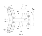
- FIG. 4 is a plan view of the front heater at a position along line IV-IV in FIG. 2.
- FIG. 5 is a plan view of the front heater at a position along the line VV in FIG. 2.
- It is a cross-sectional side view of the front side heater and back side heater in the modification of 1st Embodiment.
- It is a cross-sectional side view of the front side heater and back side heater in another modification of 1st Embodiment.
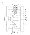
- FIG. 1 It is a schematic block diagram of the spinning shaping
- a heater that heats the deformation target portion of the plate member may be configured to have a pair of lead portions that extend from the coil portion outward in the radial direction of the rotation shaft.
- the first embodiment is mainly intended to prevent contact between the plate material and the lead portion.
- the processing tool presses the deformation target portion of the plate material in the axial direction of the rotating shaft while being moved radially outward of the rotating shaft. That is, as the deformation target portion moves radially outward, the diameter of the conical portion (the so-called portion immediately after molding) formed immediately inside the deformation target portion gradually increases.
- the radius of the coil part of the heater that heats the deformation target part is usually constant.
- the heater generally has a core for concentrating magnetic flux that covers the coil portion from the side opposite to the plate material. Therefore, when the heater is disposed on the same side as the processing tool, there is a possibility that the portion immediately after the plate material is formed contacts the core of the heater.
- the second and third embodiments are mainly intended to prevent contact between the immediately after molding of the plate material and the core.
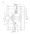
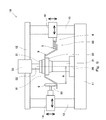
- FIG. 1 shows a spinning molding apparatus 1A according to the first embodiment of the present invention.
- the spinning molding apparatus 1 ⁇ / b> A includes a rotating shaft 21, a receiving jig 22 attached to the rotating shaft 21, and a fixing jig 31.
- the receiving jig 22 supports the central portion 91 of the plate material 9 to be molded, and the fixing jig 31 holds the plate material 9 together with the receiving jig 22.
- the spinning forming apparatus 1A includes a front side heater 5 and a back side heater 4 that locally heat a deformation target portion 92 that is a predetermined distance R away from the axis 20 of the rotating shaft 21 of the plate member 9 by induction heating, A processing tool 8 for pressing the target portion 92 to deform the plate material 9 is provided.
- the deformation target portion 92 changes from the molding start position Ps to the molding end position Pf so that the predetermined distance R gradually increases.
- the axial direction of the rotating shaft 21 (the direction in which the axis 20 extends) is the vertical direction in this embodiment.
- the axial direction of the rotating shaft 21 may be a horizontal direction or an oblique direction.
- a lower portion of the rotating shaft 21 is supported by the base 11, and a motor (not shown) that rotates the rotating shaft 21 is disposed in the base 11.
- the upper surface of the rotating shaft 21 is flat, and a receiving jig 22 is fixed to the upper surface.
- the plate material 9 is, for example, a flat circular plate.
- the shape of the plate member 9 may be a polygonal shape or an elliptical shape.
- the plate 9 does not necessarily need to be flat over the entire surface.
- the thickness of the central portion 91 is greater than the thickness of the peripheral portion 93, or the whole or a part thereof is processed into a tapered shape in advance. Also good.
- plate material 9 is not specifically limited, For example, it is a titanium alloy.
- the receiving jig 22 has a size that fits in a circle defined by the molding start position Ps in the plate material 9.
- the diameter of the receiving jig 22 is equal to or less than the diameter of a circle defined by the molding start position Ps in the plate material 9.
- the plate member 9 is not deformed by being pressed against the radially outward side surface of the receiving jig 22.
- the fixing jig 31 is attached to the pressure rod 32.
- the pressure rod 32 is driven in the vertical direction by the drive unit 33, thereby receiving the plate material 9 through the fixing jig 31 and pressing it against the jig 22.
- the pressure rod 32 and the drive unit 33 are hydraulic cylinders, and the drive unit 33 is fixed to the frame 12 disposed above the rotation shaft 21, and the pressure rod 32 is rotatably supported by the drive unit 33. Built-in bearing.
- the fixing jig 31 may be fixed to the receiving jig 22 together with the plate material 9 by a fastening member such as a bolt or a clamp.
- the fixing jig 31 may be omitted, and the plate material 9 may be received and fixed directly to the jig 22 by, for example, bolts.
- the processing tool 8 that presses the deformation target portion 92 of the plate material 9 is arranged above the plate material 9, and the plate material 9 is processed by the processing tool 8 into a shape that opens downward so as to receive the receiving jig 22. Is done. That is, the upper surface of the plate material 9 is the front surface, and the lower surface of the plate material 9 is the back surface.
- the processing tool 8 may be disposed below the plate material 9, and the processing tool 8 may process the plate material 9 so as to open upward so as to accommodate the fixing jig 31. That is, the lower surface of the plate material 9 may be the front surface, and the upper surface of the plate material 9 may be the back surface.
- the processing tool 8 is moved in the radial direction of the rotating shaft 21 by the radial moving mechanism 14 and is moved in the axial direction of the rotating shaft 21 by the axial moving mechanism 13 via the radial moving mechanism 14.
- the axial movement mechanism 13 extends so as to bridge the base 11 and the frame 12 described above.
- a roller that rotates following the rotation of the plate 9 is used as the processing tool 8.
- the processing tool 8 is not limited to a roller, and may be a spatula, for example.
- the front side heater 5 is disposed on the same side as the processing tool 8 with respect to the plate material 9, and the back side heater 4 is disposed on the opposite side of the processing tool 8 with the plate material 9 interposed therebetween.
- the front side heater 5 and the back side heater 4 are connected to the same heat station 6.
- the front side heater 5 and the back side heater 4 are arranged so as to face each other in the axial direction of the rotary shaft 21, and the heat station 6 is arranged outside the heaters 5, 4 in the radial direction of the rotary shaft 21. ing.
- the front-side heater 5 and the back-side heater 4 are moved in the radial direction of the rotary shaft 21 by the radial movement mechanism 16 via the heat station 6 and rotated by the axial movement mechanism 15 via the radial movement mechanism 16. It is moved in the axial direction of the shaft 21.
- the axial movement mechanism 15 extends so as to bridge the base 11 and the frame 12 described above.
- a displacement meter (not shown) for measuring the distance to the deformation target portion 92 of the plate material 9 is attached to either the front side heater 5 or the back side heater 4.
- the front side heater 5 and the back side heater 4 are moved in the axial direction and the radial direction of the rotary shaft 21 so that the measured value of the displacement meter becomes constant.
- the relative positions of the front side heater 5 and the back side heater 4 and the processing tool 8 are not particularly limited as long as they are located on substantially the same circumference around the axis 20 of the rotating shaft 21. Absent.
- the front side heater 5 and the back side heater 4 may be 180 degrees away from the processing tool 8 in the circumferential direction of the rotating shaft 21.
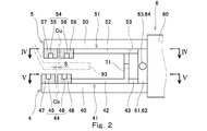
- the heat station 6 to which the front side heater 5 and the back side heater 4 are connected includes a box-shaped main body 60 and a pair of connection boxes 61 and 62 fixed to the side surface of the main body 60 facing the rotation shaft 21.
- An AC power supply circuit is formed inside the main body 60.
- the connection boxes 61 and 62 are made of a conductive member and are adjacent to each other with the insulating plate 72 interposed therebetween.
- Each of the connection boxes 61 and 62 is electrically connected to a power supply circuit in the main body 60.
- the junction boxes 61 and 62 extend in the vertical direction so as to straddle the front side heater 5 and the back side heater 4.
- connection boxes 61 and 62 are electrically connected to each other via a conductive pipe 51 of the front heater 5 and a conductive pipe 41 of the back heater 4 which will be described later. That is, an alternating current flows from one of the connection boxes 61, 62 to the other through the conduits 51, 41.
- the frequency of the alternating current is not particularly limited, but is preferably a high frequency of 5 k to 400 kHz. That is, the induction heating by the front side heater 5 and the back side heater 4 is desirably high frequency induction heating.
- connection boxes 61 and 62 are provided with coolant ports 63 and 64, respectively. Then, a coolant is supplied into one of the connection boxes 61 and 62 through a coolant port (63 or 64), and after this coolant circulates through electric pipes 51 and 41 described later, It is discharged from the other inside through the coolant port (64 or 63).
- a large current (for example, 1000 to 4000 A) can be passed through the conduits 51 and 41 by circulating the coolant through the conduits 51 and 41.
- the front side heater 5 includes a conductive pipe 51 through which a coolant flows and a support plate 50.
- the cross-sectional shape of the electrical conduit 51 is a square shape in the present embodiment, but may be another shape (for example, a circular shape).
- the support plate 50 is made of, for example, a heat resistant material (for example, a ceramic fiber material), and supports the conductive tube 51 via an insulating member (not shown).
- the support plate 50 is fixed to the main body 60 of the heat station 6 via an insulating member (not shown).
- the support plate 50 may be made of an insulating resin. In this case, the support plate 50 may directly support the conductive pipe 51, or the support plate 50 may be directly fixed to the main body 60 of the heat station 6.
- the conductive tube 51 includes a double arc-shaped coil portion 54 along the plate 9 that extends in the circumferential direction of the rotating shaft 21 and a pair of lead portions 52 and 53 that extend from the coil portion 54 outward in the radial direction of the rotating shaft 21.
- the pair of lead portions 52 and 53 are parallel to each other on a plane perpendicular to the axis 20 of the rotating shaft 21 (in this embodiment, a horizontal plane), and extend from the approximate center of the coil portion 54. That is, the coil portion 54 includes one inner arc portion 55 and two outer arc portions 56 that spread on both sides of the lead portions 52 and 53.
- the inner arc portion 55 and the outer arc portion 56 are separated from each other in the radial direction of the rotating shaft 21.
- the opening angle of the coil portion 54 (angle between both end portions) is, for example, 60 to 120 degrees.
- the lead portion 52 on one side (left side from the heat station 6 toward the rotating shaft 21 in FIG. 4) is connected to the connection box 61 described above, and the inside of the lead portion 52 communicates with the inside of the connection box 61.
- the other lead part 53 (on the right side from the heat station 6 toward the rotating shaft 21) is connected to the relay pipe 71.
- the front heater 5 includes one first core 57 that covers the inner arc portion 55 of the coil portion 54 from the side opposite to the plate material 9, and two second cores 58 that cover the outer arc portion 56 from the side opposite to the plate material 9. including.
- the first core 57 and the second core 58 are for collecting magnetic flux generated around the inner arc portion 55 and the outer arc portion 56, and a slight amount is provided between the first core 57 and the second core 58. A gap is secured.
- the first core 57 and the second core 58 are supported by the support plate 50 via an insulating member (not shown).
- the first core 57 and the second core 58 are, for example, those in which metal magnetic powder is dispersed in a resin.
- the first core 57 and the second core 58 may be made of ferrite, silicon steel, or the like.
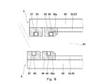
- the lead parts 52 and 53 are receded so as to be farther from the plate material 9 than the coil part 54 at the end part on the coil part 54 side. In other words, a step is formed between the coil portion 54 and the portion of the lead portions 52 and 53 parallel to the radial direction of the rotating shaft 21.
- the lead portions 52 and 53 retreat in the axial direction of the rotary shaft 21 by the thickness of the groove bottom of the cores 57 and 58 (the portion between the arc portion (55 or 56) and the support plate 50). is doing. That is, the end portions of the lead portions 52 and 53 on the coil portion 54 side are bent upward at 90 degrees in the horizontal direction after extending upward from the central end portion of the outer arc portion 56.
- the shape in which the lead portions 52 and 53 are retracted is not limited to this.
- the end portions of the lead portions 52 and 53 on the coil portion 54 side may be bent in the horizontal direction after extending obliquely upward from the central end portion of the outer arc portion 56.
- the backside heater 4 includes a conductive tube 41 through which a coolant flows and a support plate 40.
- the cross-sectional shape of the electrical conduit 41 is a square shape in the present embodiment, but may be another shape (for example, a circular shape).
- the support plate 40 is made of, for example, a heat-resistant material (for example, a ceramic fiber material), and supports the conductive tube 41 via an insulating member (not shown).
- the support plate 40 is fixed to the main body 60 of the heat station 6 via an insulating member (not shown).
- the support plate 40 may be made of an insulating resin. In this case, the support plate 40 may directly support the conductive tube 41 or may be directly fixed to the main body 60 of the heat station 6.
- the conductive tube 41 has a double arc-shaped coil portion 44 along the plate 9 that extends in the circumferential direction of the rotating shaft 21, and a pair of lead portions 42 and 43 that extend from the coil portion 44 outward in the radial direction of the rotating shaft 21.
- the pair of lead portions 42 and 43 are parallel to each other on a plane (horizontal plane in the present embodiment) perpendicular to the axis 20 of the rotating shaft 21, and extend from substantially the center of the coil portion 44. That is, the coil portion 44 includes one inner arc portion 45 and two outer arc portions 46 that spread on both sides of the lead portions 42 and 43.
- the inner arc portion 45 and the outer arc portion 46 are separated from each other in the radial direction of the rotating shaft 21.
- the opening angle of the coil portion 44 (angle between both end portions) is, for example, 60 to 120 degrees.
- the lead part 42 on one side (on the right side from the heat station 6 toward the rotating shaft 21 in FIG. 5) is connected to the connection box 62 described above, and the inside of the lead part 42 communicates with the inside of the connection box 62.
- the other lead portion 43 (on the left side from the heat station 6 toward the rotating shaft 21) is connected to the relay pipe 71.
- the back heater 4 includes one first core 47 that covers the inner arc portion 45 of the coil portion 44 from the side opposite to the plate material 9, and two second cores 48 that cover the outer arc portion 46 from the side opposite to the plate material 9. including.
- the first core 47 and the second core 48 are for collecting magnetic flux generated around the inner arc portion 45 and the outer arc portion 46, and a slight amount is provided between the first core 47 and the second core 48. A gap is secured.
- the first core 47 and the second core 48 are supported by the support plate 40 via an insulating member (not shown).
- the first core 47 and the second core 48 are, for example, ones in which metal magnetic powder is dispersed in a resin.
- the first core 47 and the second core 48 may be made of ferrite, silicon steel, or the like.
- the lead parts 42 and 43 are receded so as to be farther from the plate material 9 than the coil part 44 at the end part on the coil part 44 side.
- a step is formed between the coil portion 44 and a portion of the lead portions 42 and 43 parallel to the radial direction of the rotating shaft 21.
- the lead portions 42 and 43 retreat in the axial direction of the rotary shaft 21 by the thickness of the groove bottoms of the cores 47 and 48 (the portion between the arc portion (45 or 46) and the support plate 40). is doing. That is, the end portions of the lead portions 42 and 43 on the coil portion 44 side extend downward from the central end portion of the outer arc portion 46 and then bend in the horizontal direction by 90 degrees.
- the shape in which the lead portions 42 and 43 retreat is not limited to this.
- the end portions of the lead portions 42 and 43 on the coil portion 44 side may be bent in the horizontal direction after extending obliquely downward from the central end portion of the outer arc portion 46.
- the above-described right lead portion 53 of the front heater 5 and the left lead portion 42 of the back heater 4 are connected to each other by a relay pipe 71 that is bent in a crank shape. In other words, not the lead portions at the same position in the front heater 5 and the back heater 4 but the lead portions at different positions are connected. As a result, the coolant and current flow in the same direction through the coil portion 54 of the front heater 5 and the coil portion 44 of the back heater 4. However, it is also possible to connect the lead portions at the same position in the front side heater 5 and the back side heater 4.
- the lead portions 42 and 43 of the back side heater 4 are retracted so as to be farther from the plate material 9 than the coil portion 44 at the end portion on the coil portion 44 side.
- the lead parts 52 and 53 of the front heater 5 are retracted so as to be farther from the plate material 9 than the coil part 54 at the end part on the coil part 54 side. For this reason, even if the peripheral edge portion 93 of the plate material 1 is deformed so as to hang down or warped upward, the peripheral edge portion 93 of the plate material 9 is in contact with the lead portions 42, 43, 52, 53. Can be prevented.
- the lead portion is retracted by only one of the back side heater 4 and the front side heater 5.
- the lead part (42, 43 or 52, 53) may extend straight from the coil part (44 or 54) in the radial direction of the rotary shaft 21. . That is, on the other side of the back side heater 4 and the front side heater 5, no step may be formed between the lead portion and the coil portion.
- the position of the center Cu of the coil part 54 of the front side heater 5 is radially outside of the rotary shaft 21 from the position of the center Cb of the coil part 44 of the back side heater 4. Is shifted by a predetermined distance S.
- the relationship between the predetermined distance S, the radius of curvature Ru of the center Cu of the coil portion 54 of the front heater 5 (see FIG. 4), and the radius of curvature Rb of the center Cb of the coil portion 44 of the back heater 4 (see FIG. 5). Is the following equation 1, 0.5S ⁇ Ru ⁇ Rb ⁇ 1.5S (Formula 1) It is desirable to satisfy.
- the processing tool 8 presses the deformation target portion 92 of the plate 9 in the axial direction of the rotating shaft 21 while being moved radially outward of the rotating shaft 21. For this reason, the diameter of the conical part (the so-called part immediately after molding) formed immediately inside the deformation target part 92 is gradually increased.
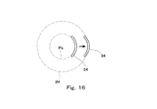
- the radius of the coil portion 54 of the front heater 5 that heats the deformation target portion 92 is constant. Accordingly, as shown in FIG. 16, if the radius of the coil portion 54 is made to coincide with the radius of the molding start position Ps, both ends of the coil portion 54 are more than the molding end position Pf in plan view at the end of molding.
- the portion immediately after the molding of the plate material 9 comes into contact with the first core 57. If it is the structure which satisfy
- filling said Formula 1 may correspond with the radius of the shaping
- the lead portions (42, 43, 52, 53) of the back-side heater 4 and the front-side heater 5 are separated from the plate material 9 in one step at the end portions on the coil portion (44, 54) side.
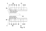
- at least one lead part of the back side heater 4 and the front side heater 5 may be retracted so as to move away from the plate material 9 in at least two stages at the end on the coil part side. According to this configuration, contact between the peripheral edge portion 93 of the plate member 9 and the lead portion can be more effectively prevented.
- a spacer 59 is inserted between the first core 57 and the second core 58 of the front heater 5 and the support plate 50, and the first step is the same as in the first embodiment,
- the lead portions 52 and 53 may be moved backward by the thickness of the spacer 59.
- a spacer 49 is inserted between the first core 47 and the second core 48 of the back side heater 4 and the support plate 40, and the first step is the same as the first embodiment, and the second step is the reverse.
- the lead portions 42 and 43 may be retracted by the thickness of the spacer 49.
- the lead parts 52 and 53 may be retracted by one stage with the front side heater 5, and the lead parts 42 and 43 may be retracted in two stages with the back side heater 4.
- the lead portions 42 and 43 may be retracted by one stage with the back side heater 4, and the lead portions 52 and 53 may be retracted in two stages with the front side heater 5.
- the lead part (42, 43 and / or 52, 53) is retracted so as to be smoothly curved as shown in FIG. May be. According to this configuration, the coolant can flow smoothly over the entire length of the conducting pipe (41 and / or 51), and air bubbles can be prevented from remaining in the conducting pipe. Accordingly, good cooling performance can be obtained, and melting of the electrical conduit can be prevented.
- At least one of the front side heater 5 and the back side heater 4 is an outer wall portion (in the radial outer side of the outer arc portion (56, 46) in the second core (58, 48)) ( 58a, 48a) may have a shape that narrows toward the tip.
- the outer wall portion may have a shape in which the radially outer tip corner portion is cut obliquely.
- an inclined surface is formed on the outer wall portion so that a part of the flat tip surface on the same surface as the surface facing the plate member 9 in the outer arc portion remains or no tip surface remains at all. May be. According to this configuration, contact between the peripheral edge portion 93 of the plate member 9 and the second core can also be prevented.
- the spinning molding apparatus 1A does not necessarily have both the front side heater 5 and the back side heater 4, and may have only one of them. However, if the spinning molding apparatus 1A has at least the back-side heater 4, the back-side heater 4 can be positioned in the vicinity of the deformation target portion 92 of the plate 9 regardless of the shape of the plate 9 being processed. it can. Thereby, the deformation
- the spinning molding apparatus 1B has only the front heater 5.
- the spinning molding apparatus 1B may also have the back heater 4 as in the first embodiment.
- the front side heater 5 and the back side heater 4 may be connected to the same heat station 6, or may be connected to different heat stations 6A and 6B (see FIG. 15) as in the third embodiment described later. It may be connected.
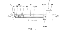
- the pair of lead portions 52 and 53 of the conducting tube 51 extends straight from the coil portion 54 in the radial direction of the rotary shaft 21 and is connected to the connection boxes 61 and 62.
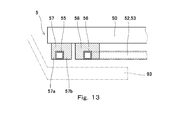
- the first core 57 that covers the inner arc portion 55 of the coil portion 54 from the side opposite to the plate member 9 includes an inner wall portion 57 a that is located on the radially inner side of the inner arc portion 55, and the inner arc portion 55. And an outer wall portion 57b located on the radially outer side.
- the outer wall portion 57b has a certain width (dimension in the radial direction of the rotating shaft 21) from the base portion to the tip end.
- at least a part of the inner wall portion 57a has a shape that narrows toward the tip.
- the inner wall portion 57a has a shape such that the radially inner tip corner portion is cut obliquely.
- the inclined surface is formed on the inner wall portion 57a so that a part of the flat front end surface on the same surface as the surface facing the plate member 9 in the inner circular arc portion 55 remains.
- the inclined surface may be formed so that the tip surface of the inner wall portion 57a does not remain at all.
- the processing tool 8 presses the deformation target portion 92 of the plate 9 in the axial direction of the rotating shaft 21 while being moved radially outward of the rotating shaft 21. For this reason, the diameter of the conical part (the so-called part immediately after molding) formed immediately inside the deformation target part 92 is gradually increased.
- the radius of the coil portion 54 of the front heater 5 that heats the deformation target portion 92 is constant. Accordingly, as shown in FIG. 16, if the radius of the coil portion 54 is made to coincide with the radius of the molding start position Ps, both ends of the coil portion 54 are more than the molding end position Pf in plan view at the end of molding. Since it enters the inside in the radial direction, there is a possibility that the portion immediately after the molding of the plate material 9 comes into contact with the first core 57.
- the inner wall portion 57a of the first core 57 has a shape that narrows toward the tip as in the spinning molding apparatus 1B of the present embodiment, the portion immediately after molding of such a plate material 9 and the front side Contact with the first core 57 of the heater 5 can be suppressed.
- the radius of the coil part 54 may correspond with the radius of the shaping
- the first core 57 may have any shape as long as the shape of the inner wall portion 57a becomes narrower toward the tip.
- the outline of the cross-sectional shape of the first core 57 is a shape obtained by linearly cutting a part of a circle (eg, 1/10 to 1/3 of the diameter). May be.
- the shape of the inner wall portion 57a does not necessarily need to be narrowed toward the tip.
- the inner wall portion 57a may be thinner than the outer wall portion 57b. Even with this configuration, the same effect as in the second embodiment can be obtained.
- the position of the center Cu of the coil part 54 of the front side heater 5 is the center of the coil part 44 of the back side heater 4 as in the first embodiment.
- the position may be shifted by a predetermined distance S from the position of Cb to the outside in the radial direction of the rotating shaft 21.
- the predetermined distance S, the radius of curvature Ru (see FIG. 4) of the center Cu of the coil portion 54 of the front side heater 5, and the radius of curvature Rb (see FIG. 5) of the center Cb of the coil portion 44 of the back side heater 4 The relation of 0.5S ⁇ Ru ⁇ Rb ⁇ 1.5S (Formula 1) It is desirable to satisfy. If it is this structure, the contact with the 1st core 57 of the front heater 5 and the part immediately after shaping
- FIG. 15 a spinning forming apparatus 1C according to a third embodiment of the present invention will be described.
- this embodiment it is comprised so that the front side heater 5 and the back side heater 4 can move to radial direction separately.
- the front side heater 5 and the back side heater 4 are connected to separate heat stations 6A and 6B.
- the back side heater 4 is moved in the radial direction of the rotary shaft 21 by the first radial direction moving mechanism 17 via the heat station 6A.
- the front heater 5 is moved in the radial direction of the rotating shaft 21 by the second radial moving mechanism 18 via the heat station 6B.
- the front side heater 5 and the back side heater 4 are moved in the axial direction of the rotary shaft 21 by the axial direction moving mechanism 15 via the radial direction moving mechanisms 17 and 18.
- the second radial movement mechanism 18 is configured so that the front side heater 5 is faster in the radial direction of the rotary shaft 21 than the first radial movement mechanism 17 moves the back side heater 4 in the radial direction of the rotary shaft 21. Move to. That is, as the molding of the plate material 9 proceeds, the front side heater 5 moves further away from the axis 20 of the rotating shaft 21 than the back side heater 4.
- each of the heat stations 6A and 6B includes a main body 60 (see FIG. 2) in which an AC power supply circuit is formed, and the conduction pipe 41 of the back side heater 4 and the conduction pipe 51 of the front side heater 5 include Independent current and coolant flow.
- the processing tool 8 presses the deformation target portion 92 of the plate 9 in the axial direction of the rotating shaft 21 while being moved radially outward of the rotating shaft 21. For this reason, the diameter of the conical part (the so-called part immediately after molding) formed immediately inside the deformation target part 92 is gradually increased.
- the radius of the coil portion 54 of the front heater 5 that heats the deformation target portion 92 is constant. Accordingly, as shown in FIG. 16, if the radius of the coil portion 54 is made to coincide with the radius of the molding start position Ps, both ends of the coil portion 54 are more than the molding end position Pf in plan view at the end of molding. Since it enters the inside in the radial direction, there is a possibility that the portion immediately after the molding of the plate material 9 comes into contact with the first core 57.
- the front side heater 5 moves in the radial direction of the rotating shaft 21 at a faster speed than the back side heater 4 as in the spinning molding apparatus 1C of the present embodiment, a portion immediately after the molding of the plate material 9 is performed. And contact with the first core 57 of the front heater 5 can be suppressed.
- the radius of the coil part 54 may correspond with the radius of the shaping
- the present invention is useful when spinning a plate made of various materials.
Landscapes
- Engineering & Computer Science (AREA)
- Mechanical Engineering (AREA)
- Physics & Mathematics (AREA)
- Electromagnetism (AREA)
- Shaping Metal By Deep-Drawing, Or The Like (AREA)
- General Induction Heating (AREA)
- Lining Or Joining Of Plastics Or The Like (AREA)
Abstract
Description
図1に、本発明の第1実施形態に係るスピニング成形装置1Aを示す。このスピニング成形装置1Aは、回転軸21と、回転軸21に取り付けられた受け治具22と、固定治具31を備えている。受け治具22は、成形されるべき板材9の中心部91を支持し、固定治具31は、受け治具22と共に板材9を挟持する。さらに、スピニング成形装置1Aは、板材9における回転軸21の軸心20から所定距離Rだけ離れた変形対象部位92を誘導加熱により局所的に加熱する表側加熱器5および裏側加熱器4と、変形対象部位92を押圧して板材9を変形させる加工具8を備えている。
0.5S≦Ru-Rb≦1.5S ・・・(式1)
を満たすことが望ましい。
第1実施形態では、裏側加熱器4および表側加熱器5のリード部(42,43,52,53)が、コイル部(44,54)側の端部で、一段で板材9から遠ざかるように後退している。しかし、裏側加熱器4および表側加熱器5の少なくとも一方のリード部が、コイル部側の端部で、少なくとも二段で板材9から遠ざかるように後退していてもよい。この構成によれば、板材9の周縁部93とリード部との接触をより効果的に防止することができる。
次に、図9~12を参照して、本発明の第2実施形態に係るスピニング成形装置1Bを説明する。なお、本実施形態および後述する第3実施形態において、第1実施形態と同一構成要素には同一符号を付し、重複した説明は省略する。
第1コア57は、内壁部57aの形状が先端に向かって細くなっていれば、どのような形状を有していてもよい。例えば、図14に示すように、第1コア57の断面形状の輪郭は、円の一部(例えば、直径の1/10~1/3の部分)を直線的に切断したような形状であってもよい。
0.5S≦Ru-Rb≦1.5S ・・・(式1)
を満たすことが望ましい。この構成であれば、板材9の成形直後部分と表側加熱器5の第1コア57との接触をより効果的に抑制できる。
次に、図15を参照して、本発明の第3実施形態に係るスピニング成形装置1Cを説明する。本実施形態では、表側加熱器5と裏側加熱器4が別々に径方向に移動できるように構成されている。
13,15 軸方向移動機構
14,16 径方向移動機構
17 第1径方向移動機構
18 第2径方向移動機構
21 回転軸
22 受け治具
4 裏側加熱器
5 表側加熱器
41,51 電通管
42,43,52,53 リード部
44,54 コイル部
45,55 内側円弧部
46,56 外側円弧部
47,57 第1コア
48,58 第2コア
57a 内壁部
57b,48a 外壁部
8 加工具
9 板材
91 中心部
92 変形対象部位
Claims (9)
- 成形されるべき板材の中心部を支持する受け治具と、
前記受け治具が取り付けられた回転軸と、
前記板材における変形対象部位を押圧して前記板材を変形させる加工具と、
前記変形対象部位を誘導加熱により局所的に加熱する加熱器と、を備え、
前記加熱器は、内部に冷却液が流れる電通管であって、前記回転軸の周方向に延びる、前記板材に沿った二重円弧状のコイル部、および前記コイル部から前記回転軸の径方向外向きに延びる一対のリード部を有する電通管を含み、
前記一対のリード部は、前記コイル部側の端部で、前記コイル部よりも前記板材から遠ざかるように後退している、スピニング成形装置。 - 前記一対の前記リード部は、少なくとも二段で前記板材から遠ざかるように後退している、請求項1に記載のスピニング成形装置。
- 前記加熱器は、前記板材を挟んで前記加工具と反対側に配置された裏側加熱器である、請求項1または2に記載のスピニング成形装置。
- 前記加熱器は、前記板材を挟んで前記加工具と反対側に配置された裏側加熱器と、前記板材に対して前記加工具と同じ側に配置された表側加熱器の両方である、請求項1または2に記載のスピニング成形装置。
- 前記裏側加熱器は、前記コイル部の内側円弧部を前記板材と反対側から覆う第1コアと、前記コイル部の外側円弧部を前記板材と反対側から覆う第2コアと、を含み、
前記第2コアにおける前記外側円弧部の径方向外側に位置する外壁部の少なくとも一部が、先端に向かって細くなる形状を有している、請求項3または4に記載のスピニング成形装置。 - 成形されるべき板材の中心部を支持する受け治具と、
前記受け治具が取り付けられた回転軸と、
前記板材における変形対象部位を押圧して前記板材を変形させる加工具と、
前記変形対象部位を誘導加熱により局所的に加熱する、前記板材に対して前記加工具と同じ側に配置された表側加熱器と、を備え、
前記表側加熱器は、内部に冷却液が流れる電通管であって、前記回転軸の周方向に延びる、前記板材に沿った二重円弧状のコイル部を有する電通管と、前記コイル部の内側円弧部を前記板材と反対側から覆う第1コアと、前記コイル部の外側円弧部を前記板材と反対側から覆う第2コアと、を含み、
前記第1コアにおける前記内側円弧部の径方向内側に位置する内壁部の少なくとも一部が、先端に向かって細くなる形状を有する、または第1コアにおける前記内側円弧部の径方向外側に位置する外壁部よりも細くなっている、スピニング成形装置。 - 前記板材における変形対象部位を誘導加熱により局所的に加熱する、前記板材を挟んで前記加工具と反対側に配置された裏側加熱器をさらに備え、
前記裏側加熱器は、内部に冷却液が流れる電通管であって、前記回転軸の周方向に延びる、前記板材に沿った二重円弧状のコイル部を有する電通管を含む、請求項6に記載のスピニング成形装置。 - 前記表側加熱器のコイル部の中心位置は、前記裏側加熱器のコイル部の中心位置から前記回転軸の径方向外側に所定距離だけずれており、
前記所定距離をS、前記表側加熱器のコイル部の中心の曲率半径をRu、前記裏側加熱器のコイル部の中心の曲率半径をRbとしたとき、以下の式
0.5S≦Ru-Rb≦1.5S
を満たす、請求項4または7に記載のスピニング成形装置。 - 成形されるべき板材の中心部を支持する受け治具と、
前記受け治具が取り付けられた回転軸と、
前記板材における変形対象部位を押圧して前記板材を変形させる加工具と、
前記変形対象部位を誘導加熱により局所的に加熱する、前記板材に対して前記加工具と同じ側に配置された表側加熱器と、
前記変形対象部位を誘導加熱により局所的に加熱する、前記板材を挟んで前記加工具と反対側に配置された裏側加熱器と、
前記表側加熱器および前記裏側加熱器を前記回転軸の軸方向に移動させる軸方向移動機構と、
前記裏側加熱器を前記回転軸の径方向に移動させる第1径方向移動機構と、
前記表側加熱器を前記裏側加熱器よりも速い速度で前記回転軸の径方向に移動させる第2径方向移動機構と、を備え、
前記表側加熱器および前記裏側加熱器のそれぞれは、内部に冷却液が流れる電通管であって、前記回転軸の周方向に延びる、前記板材に沿った二重円弧状のコイル部を有する電通管と、前記コイル部の内側円弧部を前記板材と反対側から覆う第1コアと、前記コイル部の外側円弧部を前記板材と反対側から覆う第2コアと、を含む、スピニング成形装置。
Priority Applications (5)
| Application Number | Priority Date | Filing Date | Title |
|---|---|---|---|
| EP14874203.4A EP3095535B1 (en) | 2013-12-24 | 2014-12-16 | Spinning forming device |
| EP18197307.4A EP3446802B1 (en) | 2013-12-24 | 2014-12-16 | Spinning forming device |
| US15/108,121 US10092939B2 (en) | 2013-12-24 | 2014-12-16 | Spinning forming device |
| CN201480066393.4A CN105764626B (zh) | 2013-12-24 | 2014-12-16 | 旋压成形装置 |
| KR1020167017197A KR101852095B1 (ko) | 2013-12-24 | 2014-12-16 | 스피닝 성형 장치 |
Applications Claiming Priority (2)
| Application Number | Priority Date | Filing Date | Title |
|---|---|---|---|
| JP2013265535A JP6259656B2 (ja) | 2013-12-24 | 2013-12-24 | スピニング成形装置 |
| JP2013-265535 | 2013-12-24 |
Publications (1)
| Publication Number | Publication Date |
|---|---|
| WO2015098044A1 true WO2015098044A1 (ja) | 2015-07-02 |
Family
ID=53477949
Family Applications (1)
| Application Number | Title | Priority Date | Filing Date |
|---|---|---|---|
| PCT/JP2014/006279 Ceased WO2015098044A1 (ja) | 2013-12-24 | 2014-12-16 | スピニング成形装置 |
Country Status (7)
| Country | Link |
|---|---|
| US (1) | US10092939B2 (ja) |
| EP (2) | EP3446802B1 (ja) |
| JP (1) | JP6259656B2 (ja) |
| KR (1) | KR101852095B1 (ja) |
| CN (1) | CN105764626B (ja) |
| TW (1) | TWI568517B (ja) |
| WO (1) | WO2015098044A1 (ja) |
Families Citing this family (5)
| Publication number | Priority date | Publication date | Assignee | Title |
|---|---|---|---|---|
| DE102015113869A1 (de) * | 2015-08-20 | 2017-02-23 | Thyssenkrupp Ag | Verfahren zum Herstellen eines Formteils und Formteil |
| CN105583304B (zh) * | 2016-03-01 | 2017-09-22 | 芜湖同创模具机械有限公司 | 一种汽车铝件成型模具 |
| CN106392499A (zh) * | 2016-12-02 | 2017-02-15 | 中国航天科技集团公司长征机械厂 | 一种等壁厚曲母线零件精确成形方法 |
| CN106862316B (zh) * | 2017-01-13 | 2018-07-24 | 大楚神驰车轮股份有限公司 | 一种用于车轮轮辐的整圆装置 |
| CN114798917A (zh) * | 2020-07-31 | 2022-07-29 | 郑雷 | 一种冷却效果优异的冲压模具及其冲压工艺 |
Citations (9)
| Publication number | Priority date | Publication date | Assignee | Title |
|---|---|---|---|---|
| JPS4841965A (ja) * | 1971-09-29 | 1973-06-19 | ||
| JPH0279594U (ja) * | 1988-12-08 | 1990-06-19 | ||
| JP2006294396A (ja) * | 2005-04-11 | 2006-10-26 | Shimada Phys & Chem Ind Co Ltd | 誘導加熱装置 |
| JP2008276974A (ja) * | 2007-04-25 | 2008-11-13 | Shimadzu Corp | 高周波誘導加熱装置 |
| JP2011218427A (ja) | 2010-04-13 | 2011-11-04 | Society Of Japanese Aerospace Co Inc | 成形方法および成形装置 |
| JP2012178269A (ja) | 2011-02-25 | 2012-09-13 | Toyota Industries Corp | リチウムイオン二次電池用負極活物質、および、その負極活物質を用いたリチウムイオン二次電池 |
| WO2014024384A1 (ja) * | 2012-08-10 | 2014-02-13 | 川崎重工業株式会社 | スピニング成形装置および成形方法 |
| WO2014034140A1 (ja) * | 2012-09-03 | 2014-03-06 | 川崎重工業株式会社 | スピニング成形方法及びスピニング成形装置 |
| WO2014097551A1 (ja) * | 2012-12-18 | 2014-06-26 | 川崎重工業株式会社 | スピニング成形装置 |
Family Cites Families (5)
| Publication number | Priority date | Publication date | Assignee | Title |
|---|---|---|---|---|
| US5687599A (en) * | 1996-01-04 | 1997-11-18 | Reynolds Metals Company | Method of forming a can with an electromagnetically formed contoured sidewall and necked end |
| JP2013161767A (ja) * | 2012-02-09 | 2013-08-19 | Kansai Electric Power Co Inc:The | Ih式加熱調理器 |
| CN203209511U (zh) * | 2012-12-31 | 2013-09-25 | 常州旷达威德机械有限公司 | 热旋压机 |
| CN103394575B (zh) * | 2013-08-12 | 2015-07-01 | 赤壁苍龙管件有限责任公司 | 一种波形炉胆旋压成形工艺 |
| JP6445776B2 (ja) * | 2014-04-11 | 2018-12-26 | 川崎重工業株式会社 | スピニング成形方法 |
-
2013
- 2013-12-24 JP JP2013265535A patent/JP6259656B2/ja active Active
-
2014
- 2014-12-16 EP EP18197307.4A patent/EP3446802B1/en active Active
- 2014-12-16 EP EP14874203.4A patent/EP3095535B1/en active Active
- 2014-12-16 WO PCT/JP2014/006279 patent/WO2015098044A1/ja not_active Ceased
- 2014-12-16 CN CN201480066393.4A patent/CN105764626B/zh not_active Expired - Fee Related
- 2014-12-16 KR KR1020167017197A patent/KR101852095B1/ko not_active Expired - Fee Related
- 2014-12-16 US US15/108,121 patent/US10092939B2/en active Active
- 2014-12-19 TW TW103144463A patent/TWI568517B/zh not_active IP Right Cessation
Patent Citations (9)
| Publication number | Priority date | Publication date | Assignee | Title |
|---|---|---|---|---|
| JPS4841965A (ja) * | 1971-09-29 | 1973-06-19 | ||
| JPH0279594U (ja) * | 1988-12-08 | 1990-06-19 | ||
| JP2006294396A (ja) * | 2005-04-11 | 2006-10-26 | Shimada Phys & Chem Ind Co Ltd | 誘導加熱装置 |
| JP2008276974A (ja) * | 2007-04-25 | 2008-11-13 | Shimadzu Corp | 高周波誘導加熱装置 |
| JP2011218427A (ja) | 2010-04-13 | 2011-11-04 | Society Of Japanese Aerospace Co Inc | 成形方法および成形装置 |
| JP2012178269A (ja) | 2011-02-25 | 2012-09-13 | Toyota Industries Corp | リチウムイオン二次電池用負極活物質、および、その負極活物質を用いたリチウムイオン二次電池 |
| WO2014024384A1 (ja) * | 2012-08-10 | 2014-02-13 | 川崎重工業株式会社 | スピニング成形装置および成形方法 |
| WO2014034140A1 (ja) * | 2012-09-03 | 2014-03-06 | 川崎重工業株式会社 | スピニング成形方法及びスピニング成形装置 |
| WO2014097551A1 (ja) * | 2012-12-18 | 2014-06-26 | 川崎重工業株式会社 | スピニング成形装置 |
Non-Patent Citations (1)
| Title |
|---|
| See also references of EP3095535A4 |
Also Published As
| Publication number | Publication date |
|---|---|
| JP6259656B2 (ja) | 2018-01-10 |
| JP2015120184A (ja) | 2015-07-02 |
| KR101852095B1 (ko) | 2018-04-25 |
| TW201536445A (zh) | 2015-10-01 |
| EP3095535A1 (en) | 2016-11-23 |
| EP3446802A1 (en) | 2019-02-27 |
| CN105764626B (zh) | 2017-11-03 |
| EP3446802B1 (en) | 2022-03-02 |
| CN105764626A (zh) | 2016-07-13 |
| EP3095535A4 (en) | 2018-04-04 |
| US10092939B2 (en) | 2018-10-09 |
| KR20160091407A (ko) | 2016-08-02 |
| TWI568517B (zh) | 2017-02-01 |
| US20160325335A1 (en) | 2016-11-10 |
| EP3095535B1 (en) | 2021-04-28 |
Similar Documents
| Publication | Publication Date | Title |
|---|---|---|
| JP6259656B2 (ja) | スピニング成形装置 | |
| JP6118406B2 (ja) | スピニング増肉成形方法およびスピニング増肉成形装置 | |
| CN105980074B (zh) | 旋压成型方法 | |
| JP6383540B2 (ja) | スピニング成形装置 | |
| EP3095536B1 (en) | Spin forming device | |
| JP6352703B2 (ja) | スピニング成形装置 | |
| EP3130411B1 (en) | Spinning forming device | |
| JP6445779B2 (ja) | 予備成形体および軸対称部品の製造方法 | |
| CN202174175U (zh) | 一种弯管接头的冲压模具 | |
| CN109414744B (zh) | 旋压成型方法 | |
| JPH11299144A (ja) | 高速回転機の回転子構造と溝の加工方法 | |
| WO2015166634A1 (ja) | スピニング成形装置 | |
| JPWO2022244083A5 (ja) | ||
| WO2014192349A1 (ja) | 誘導回転電機用ロータの製造方法 | |
| JP2014236573A (ja) | 誘導回転電機用ロータの製造方法 |
Legal Events
| Date | Code | Title | Description |
|---|---|---|---|
| 121 | Ep: the epo has been informed by wipo that ep was designated in this application |
Ref document number: 14874203 Country of ref document: EP Kind code of ref document: A1 |
|
| NENP | Non-entry into the national phase |
Ref country code: DE |
|
| WWE | Wipo information: entry into national phase |
Ref document number: 15108121 Country of ref document: US |
|
| ENP | Entry into the national phase |
Ref document number: 20167017197 Country of ref document: KR Kind code of ref document: A |
|
| REEP | Request for entry into the european phase |
Ref document number: 2014874203 Country of ref document: EP |
|
| WWE | Wipo information: entry into national phase |
Ref document number: 2014874203 Country of ref document: EP |