WO2015099159A1 - 蓄電システム、及び蓄電方法 - Google Patents
蓄電システム、及び蓄電方法 Download PDFInfo
- Publication number
- WO2015099159A1 WO2015099159A1 PCT/JP2014/084646 JP2014084646W WO2015099159A1 WO 2015099159 A1 WO2015099159 A1 WO 2015099159A1 JP 2014084646 W JP2014084646 W JP 2014084646W WO 2015099159 A1 WO2015099159 A1 WO 2015099159A1
- Authority
- WO
- WIPO (PCT)
- Prior art keywords
- storage battery
- voltage
- power
- threshold
- switching unit
- Prior art date
- Legal status (The legal status is an assumption and is not a legal conclusion. Google has not performed a legal analysis and makes no representation as to the accuracy of the status listed.)
- Ceased
Links
Images







Classifications
-
- H—ELECTRICITY
- H10—SEMICONDUCTOR DEVICES; ELECTRIC SOLID-STATE DEVICES NOT OTHERWISE PROVIDED FOR
- H10F—INORGANIC SEMICONDUCTOR DEVICES SENSITIVE TO INFRARED RADIATION, LIGHT, ELECTROMAGNETIC RADIATION OF SHORTER WAVELENGTH OR CORPUSCULAR RADIATION
- H10F77/00—Constructional details of devices covered by this subclass
- H10F77/95—Circuit arrangements
- H10F77/953—Circuit arrangements for devices having potential barriers
- H10F77/955—Circuit arrangements for devices having potential barriers for photovoltaic devices
-
- H—ELECTRICITY
- H01—ELECTRIC ELEMENTS
- H01M—PROCESSES OR MEANS, e.g. BATTERIES, FOR THE DIRECT CONVERSION OF CHEMICAL ENERGY INTO ELECTRICAL ENERGY
- H01M14/00—Electrochemical current or voltage generators not provided for in groups H01M6/00 - H01M12/00; Manufacture thereof
- H01M14/005—Photoelectrochemical storage cells
-
- H—ELECTRICITY
- H02—GENERATION; CONVERSION OR DISTRIBUTION OF ELECTRIC POWER
- H02J—ELECTRIC POWER NETWORKS; CIRCUIT ARRANGEMENTS OR SYSTEMS FOR SUPPLYING OR DISTRIBUTING ELECTRIC POWER; SYSTEMS FOR STORING ELECTRIC ENERGY
- H02J7/00—Circuit arrangements for charging or discharging batteries or for supplying loads from batteries
- H02J7/34—Parallel operation in networks using both storage and other DC sources, e.g. providing buffering
- H02J7/35—Parallel operation in networks using both storage and other DC sources, e.g. providing buffering with light sensitive cells
-
- H—ELECTRICITY
- H02—GENERATION; CONVERSION OR DISTRIBUTION OF ELECTRIC POWER
- H02J—ELECTRIC POWER NETWORKS; CIRCUIT ARRANGEMENTS OR SYSTEMS FOR SUPPLYING OR DISTRIBUTING ELECTRIC POWER; SYSTEMS FOR STORING ELECTRIC ENERGY
- H02J9/00—Circuit arrangements for emergency or stand-by power supply, e.g. for emergency lighting
- H02J9/04—Circuit arrangements for emergency or stand-by power supply, e.g. for emergency lighting in which the distribution system is disconnected from the normal source and connected to a standby source
- H02J9/06—Circuit arrangements for emergency or stand-by power supply, e.g. for emergency lighting in which the distribution system is disconnected from the normal source and connected to a standby source with automatic change-over, e.g. UPS systems
- H02J9/061—Circuit arrangements for emergency or stand-by power supply, e.g. for emergency lighting in which the distribution system is disconnected from the normal source and connected to a standby source with automatic change-over, e.g. UPS systems for DC powered loads
-
- H—ELECTRICITY
- H02—GENERATION; CONVERSION OR DISTRIBUTION OF ELECTRIC POWER
- H02S—GENERATION OF ELECTRIC POWER BY CONVERSION OF INFRARED RADIATION, VISIBLE LIGHT OR ULTRAVIOLET LIGHT, e.g. USING PHOTOVOLTAIC [PV] MODULES
- H02S40/00—Components or accessories in combination with PV modules, not provided for in groups H02S10/00 - H02S30/00
- H02S40/30—Electrical components
- H02S40/38—Energy storage means, e.g. batteries, structurally associated with PV modules
-
- H—ELECTRICITY
- H01—ELECTRIC ELEMENTS
- H01G—CAPACITORS; CAPACITORS, RECTIFIERS, DETECTORS, SWITCHING DEVICES, LIGHT-SENSITIVE OR TEMPERATURE-SENSITIVE DEVICES OF THE ELECTROLYTIC TYPE
- H01G9/00—Electrolytic capacitors, rectifiers, detectors, switching devices, light-sensitive or temperature-sensitive devices; Processes of their manufacture
- H01G9/20—Light-sensitive devices
-
- H—ELECTRICITY
- H01—ELECTRIC ELEMENTS
- H01M—PROCESSES OR MEANS, e.g. BATTERIES, FOR THE DIRECT CONVERSION OF CHEMICAL ENERGY INTO ELECTRICAL ENERGY
- H01M2220/00—Batteries for particular applications
- H01M2220/10—Batteries in stationary systems, e.g. emergency power source in plant
-
- Y—GENERAL TAGGING OF NEW TECHNOLOGICAL DEVELOPMENTS; GENERAL TAGGING OF CROSS-SECTIONAL TECHNOLOGIES SPANNING OVER SEVERAL SECTIONS OF THE IPC; TECHNICAL SUBJECTS COVERED BY FORMER USPC CROSS-REFERENCE ART COLLECTIONS [XRACs] AND DIGESTS
- Y02—TECHNOLOGIES OR APPLICATIONS FOR MITIGATION OR ADAPTATION AGAINST CLIMATE CHANGE
- Y02E—REDUCTION OF GREENHOUSE GAS [GHG] EMISSIONS, RELATED TO ENERGY GENERATION, TRANSMISSION OR DISTRIBUTION
- Y02E10/00—Energy generation through renewable energy sources
- Y02E10/50—Photovoltaic [PV] energy
-
- Y—GENERAL TAGGING OF NEW TECHNOLOGICAL DEVELOPMENTS; GENERAL TAGGING OF CROSS-SECTIONAL TECHNOLOGIES SPANNING OVER SEVERAL SECTIONS OF THE IPC; TECHNICAL SUBJECTS COVERED BY FORMER USPC CROSS-REFERENCE ART COLLECTIONS [XRACs] AND DIGESTS
- Y02—TECHNOLOGIES OR APPLICATIONS FOR MITIGATION OR ADAPTATION AGAINST CLIMATE CHANGE
- Y02E—REDUCTION OF GREENHOUSE GAS [GHG] EMISSIONS, RELATED TO ENERGY GENERATION, TRANSMISSION OR DISTRIBUTION
- Y02E60/00—Enabling technologies; Technologies with a potential or indirect contribution to GHG emissions mitigation
- Y02E60/10—Energy storage using batteries
-
- Y—GENERAL TAGGING OF NEW TECHNOLOGICAL DEVELOPMENTS; GENERAL TAGGING OF CROSS-SECTIONAL TECHNOLOGIES SPANNING OVER SEVERAL SECTIONS OF THE IPC; TECHNICAL SUBJECTS COVERED BY FORMER USPC CROSS-REFERENCE ART COLLECTIONS [XRACs] AND DIGESTS
- Y02—TECHNOLOGIES OR APPLICATIONS FOR MITIGATION OR ADAPTATION AGAINST CLIMATE CHANGE
- Y02E—REDUCTION OF GREENHOUSE GAS [GHG] EMISSIONS, RELATED TO ENERGY GENERATION, TRANSMISSION OR DISTRIBUTION
- Y02E70/00—Other energy conversion or management systems reducing GHG emissions
- Y02E70/30—Systems combining energy storage with energy generation of non-fossil origin
Definitions
- the present invention relates to a power storage system and a power storage method for storing power generated by a power generation element that performs environmental power generation in a storage battery and supplying power to an external load device.
- Patent Document 1 discloses a power generation system that obtains an appropriate power generation amount required for a solar cell based on a power demand amount and adjusts the power generation amount of the solar cell in accordance with the required power generation amount. Yes.
- Patent Documents 2 and 3 in a solar cell for outdoor use with a large generated voltage, when the voltage of the generated voltage of the solar cell is larger than the voltage of the storage battery, power is supplied to the storage battery without going through the boost converter. It is disclosed that the conversion loss in the boost converter is reduced.
- Patent Document 4 discloses that power generated by a dye-sensitized solar cell is stabilized by a regulator circuit, a booster circuit, or the like and then fed to a storage battery.
- Japanese Unexamined Patent Publication No. 2012-108829 Japanese Unexamined Patent Publication No. 2011-211885 Japanese Unexamined Patent Publication No. 62-154122 Japanese Laid-Open Patent Publication No. 2012-079322
- the present invention has been made in view of the above circumstances, and an object of the present invention is to provide a power storage system and a power storage method capable of advancing the power storage time in the storage battery in a state where the voltage of the storage battery is low. It is in.
- a power storage system includes a power generation element that performs environmental power generation, a storage battery that is supplied with power generated by the power generation element, and an output voltage of the power generation element that is a predetermined voltage.
- a DC / DC converter that converts the output voltage of the power generation element, a first switch unit that switches between supplying power directly to the storage battery or supplying power via the DC / DC converter, and the DC / DC converter
- the voltage equal to or higher than the voltage of the storage battery in the main boost mode is set as the first threshold value
- the voltage of the storage battery is compared with the voltage of the first threshold value, and the switch unit is controlled according to the comparison result.
- a first switching unit When the voltage equal to or higher than the voltage of the storage battery in the main boost mode is set as the first threshold value, the voltage of the storage battery is compared with the voltage of the first threshold value, and the switch unit is controlled according to the comparison result.
- the first switching unit controls the first switch unit to directly supply power from the power generation element to the storage battery when the voltage of the storage battery is equal to or lower than the voltage of the first threshold.
- the first switching unit is configured to supply power from the power generation element to the storage battery via the DC / DC converter when the voltage of the storage battery exceeds the voltage of the first threshold.
- a switch unit is provided that switches between supplying power directly from the power generation element to the storage battery or supplying power via the DC / DC converter. Then, the switching unit determines whether or not the voltage of the storage battery exceeds a first threshold voltage that is a predetermined voltage, and when the storage battery voltage is equal to or lower than the first threshold voltage, the power generation element directly supplies power to the storage battery.
- the switch unit is controlled to perform The switching unit controls the switch unit to charge the storage battery via the DC / DC converter when the voltage of the storage battery exceeds the first threshold voltage. Furthermore, in the power storage system according to the above aspect, when the voltage equal to or higher than the voltage of the storage battery in which the DC / DC converter is in the main boost mode is the first threshold value and the voltage of the storage battery is equal to or lower than the voltage of the first threshold value, Direct power supply to And when the voltage of a storage battery rises and exceeds the voltage of a 1st threshold value, the electrical storage system which concerns on the said aspect supplies electric power to a storage battery via a DC / DC converter.
- the voltage is boosted by the DC / DC converter.
- the battery voltage can be quickly raised without being affected by the conversion loss.
- the storage battery includes a first storage battery and a second storage battery having a capacity larger than that of the first storage battery.
- the voltage of the storage battery is the second storage battery.
- Below the threshold value only the first storage battery may be fed from the power generation element. Thereby, since the power generation element is connected only to the storage battery having a small capacity, it is possible to set the voltage to the first threshold value or more with a small amount of power, and the main boost mode can be set early.
- the electrical storage system which concerns on the said aspect WHEREIN: The 2nd switch part which switches the electrical connection state between the said 1st storage battery and the said 2nd storage battery, and a disconnection state, The voltage of the said 1st storage battery, and the said 2nd threshold value And a second switching unit that controls the second switch unit according to the comparison result, wherein the first storage battery and the second storage battery respectively supply power to the external load device.
- the second threshold value is equal to or higher than a voltage at which the external load device can be operated, and the second switching unit is configured so that the voltage of the first storage battery is equal to or lower than the voltage of the second threshold value.
- the second switch unit is controlled such that the first storage battery and the second storage battery are disconnected, and the generated power of the power generation element is supplied only to the first storage battery.
- the voltage of the first storage battery is the second threshold When the voltage exceeds the first storage battery, the second storage battery is connected to the second storage battery, and the second switch unit is controlled so that power is supplied from the first storage battery to the second storage battery. May be.
- power can be supplied from each storage battery to the external load device using two types of storage batteries having different capacities.
- the first switching unit controls the second switch unit so that the generated power of the power generation element is fed only to the first storage battery until the voltage charged in the first storage battery reaches the second threshold voltage. .
- a 2nd switching part controls a 2nd switch part so that electric power feeding is performed from a 1st storage battery to a 2nd storage battery. To do.
- the power storage system can quickly start up the output voltage that supplies power to the external load device.
- the output voltage supplied to the external load device can be raised even before the second storage battery having a large capacity is charged.
- the power storage system includes a third switch unit that switches between an electrically connected state and a disconnected state between the first storage battery and the second storage battery and the external load device, and a voltage of the first storage battery. And a third switching unit that controls the third switch unit according to the comparison result, and the voltage of the first storage battery is higher than the voltage of the third threshold value.
- the third switching unit controls the third switch unit so that the first storage battery, the second storage battery, and the external load device are connected to each other, and the first storage battery When the voltage of the third storage unit is lower than the third threshold voltage, the third switching unit is configured to disconnect the first storage battery, the second storage battery, and the external load device from each other.
- the switch unit may be controlled.
- a third switch unit that switches an electrical connection state and a disconnection state between the first storage battery and the second storage battery and the external load device is provided. Then, when the voltage of the first storage battery is higher than the third threshold voltage, the third switching unit supplies power from the power storage system to the external load device with the third switch unit connected. The third switching unit disconnects the external load device from the power storage system by setting the third switch unit in a disconnected state when the voltage of the first storage battery is lower than the third threshold voltage. Accordingly, the power storage system stops the power supply to the external load device to suppress wasteful power consumption when the voltage of the first storage battery is low, such as when the power storage device is initially charged, thereby reducing the first power storage battery. Can speed up charging.
- the voltage of the third threshold value may be set higher by a predetermined voltage than the operating voltage at which the external load device can operate and lower than the voltage of the second threshold value. Accordingly, the power storage system can reliably operate the external load device when supplying power to the external load device.
- the second switching unit has a hysteresis characteristic, and compares the voltage of the first storage battery with the voltage of the second threshold value using the hysteresis characteristic, and the second switching unit is configured to compare the first storage battery with the first storage battery.
- the second switch unit is controlled so that the first storage battery and the second storage battery are connected to each other, and the second switching unit is The first storage battery and the second storage battery are connected, and the voltage of the first storage battery is lower than the second threshold voltage by a predetermined voltage and is lower than the first threshold value.
- the second switch unit may be controlled so that the first storage battery and the second storage battery are disconnected when the voltage drops below a fourth threshold voltage higher by a voltage.
- the second switching unit when the second switching unit detects that the voltage of the first storage battery exceeds the voltage of the second threshold, the second switching unit connects between the first storage battery and the second storage battery. Thereafter, power is supplied from the first storage battery to the second storage battery, whereby the voltage of the first storage battery decreases.
- the voltage of the first storage battery is lower than the first threshold voltage by a predetermined voltage and lower than the fourth threshold voltage which is higher than the first threshold by a predetermined voltage.
- the connection between the first storage battery and the second storage battery is disconnected. That is, the second switching unit is used with hysteresis characteristics to control opening and closing of the second switch unit. Accordingly, the power storage system can supply power from the first storage battery to the second storage battery, and can prevent the voltage of the first storage battery from dropping to a voltage equal to or lower than the first threshold value. Can be made difficult to enter the cold start mode.
- the power generation element may be configured by connecting power generation element cells in series. Thereby, in the electrical storage system which concerns on the said aspect, the electric power generation element can output the required voltage.
- the power generation element may be a solar cell for low illuminance that can be used in an environment having a predetermined illuminance or less.
- the power storage system can quickly raise the output voltage to be output externally even when the power output from the low-illuminance solar battery is stored using a storage battery having a large capacity.
- a power storage method includes a storage battery that is fed by the generated power of a power generation element that performs environmental power generation, a DC / DC converter that converts an output voltage of the power generation element into a predetermined voltage, and A switch unit that switches whether the output voltage of the power generation element is directly supplied to the storage battery or the power supply via the DC / DC converter, and the voltage of the storage battery that is higher than the voltage of the storage battery in which the DC / DC converter enters the main boost mode.
- the voltage is the first threshold value
- a storage system is provided that includes a switching unit that compares the voltage of the storage battery with the voltage of the first threshold value and controls the switch unit according to the comparison result.
- the switching unit controls the switch unit to directly supply power from the power generation element to the storage battery, and
- the switching unit controls the switching unit so as to supply power to the battery via the DC / DC converter from the power generating element.
- the storage time for the storage battery can be shortened when the voltage of the storage battery is low.
- FIG. 1 is a configuration diagram illustrating a configuration example of a power storage system 101.
- FIG. It is a block diagram which shows the example which comprises storage battery A121 and storage battery B122 with a some storage battery. It is explanatory drawing which shows the aspect of charge operation to storage battery A121 and storage battery B122. It is explanatory drawing which shows the image of the change of the voltage of storage battery A121 and storage battery B122.
- FIG. 3 is a flowchart showing a flow of processing in the power storage system 101. It is an image figure which shows the example which operates the electrical storage system 101 weekly. 6 is a configuration diagram illustrating a modification of the power storage system 101.
- FIG. 2 is a configuration diagram illustrating a configuration example of a power storage system 102.
- FIG. 4 is explanatory drawing which shows the aspect of charge operation to the storage battery. 4 is a flowchart showing a flow of processing in the power storage system 102.
- 3 is a configuration diagram illustrating a configuration example of a power storage system 103.
- FIG. 1 is a configuration diagram illustrating a schematic configuration of an environment monitoring system in which a power storage system according to an embodiment of the present invention is used.
- the environmental monitoring system 1 includes a power storage system 100 that stores generated power of a power generation element that performs environmental power generation in a storage battery, and an external load device 200 that is fed from the power storage system 100.
- the external load device 200 include an environment monitoring device 210 that functions as a wireless sensor that operates without wiring or battery replacement.
- the environment monitoring device 210 includes a temperature sensor 211 that measures the temperature in a room such as an office, and a humidity sensor 212 that measures the humidity in the room.
- the environmental monitoring device 210 periodically wirelessly transmits the indoor temperature information measured by the temperature sensor 211 and the indoor humidity information measured by the humidity sensor 212 to the external monitoring system 300 by the wireless communication unit 213. To do.
- the power storage system 100 that supplies power to the external load device 200 includes a solar battery 110 that is a power generation element, a power storage device 120, and a DC / DC converter 130.
- the solar cell 110 is a solar cell for low illuminance, and is used at an illuminance of 10000 Lux or less, for example.
- the power generated by the solar battery 110 is supplied to the power storage device 120 via the DC / DC converter 130 and the power is stored in the power storage device 120.
- the power storage system 100 supplies power stored in the power storage device 120 to the external load device 200. Details of the configuration and operation of the power storage system 100 will be described later.
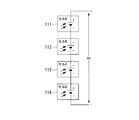
- FIGS. 2A and 2B are explanatory diagrams showing an overview of a solar cell (power generation element) and a connection state of solar cells (power generation element cells).
- a solar cell power generation element
- FIG. 2A four solar cells A111, B112, C113, and D114 are arranged in a planar shape on the light receiving surface of the solar cell 110.
- FIG. 2B the four solar cells A111, B112, C113, and D114 are connected in series to obtain a predetermined output voltage Vs.
- the solar cell 110 shown in FIGS. 2A and 2B is an example in which four solar cells are connected in series, but the number of solar cells connected in series is not limited.
- the number of solar cells is selected so that the voltage output toward the DC / DC converter 130 is a voltage at which the DC / DC converter 130 can perform a boosting operation with a predetermined efficiency or more.
- the solar cell is a low illuminance dye-sensitized solar cell, it is desirable that the number of solar cells connected in series is, for example, at least 3 or more.
- the solar battery 110 when used as an input power source, if the external load device 200 is continuously driven, it is necessary to store in the storage battery the power consumption at night when the illumination is not applied. Furthermore, when considering indoor use such as in an office, it is necessary to accumulate power consumption such as weekends and holidays. In order to increase the electric power stored in the storage battery, it is possible to cope with such a method as increasing the capacity of the storage battery or charging the storage battery to a high voltage. However, in either method, since it takes time to charge the storage battery, the time until the external load device 200 can be driven becomes longer.
- two types of storage batteries A121 and B122 having different capacities and a switch unit 140 as a switching mechanism are used to solve the above problem.
- FIG. 3 is a configuration diagram showing the configuration of the power storage system 101. 3 includes a solar battery 110 (power generation element), a power storage device 120, a DC / DC converter 130, a switch unit 140 (second switch unit), a voltage detection unit 150, and a switching unit 160. (Second switching unit).
- the solar cell 110 is a solar cell for low illuminance shown in FIGS. 2A and 2B.
- the power storage device 120 is configured by a secondary battery, a capacitor, or the like corresponding to an energy harvesting application, and is configured by a storage battery A121 having a small capacity and a storage battery B122 having a large capacity.
- the capacity of the storage battery A (first storage battery) 121 is determined based on the time from when power is supplied from the solar battery 110 to the voltage at which the external load device 200 can be driven, and when power is supplied from the storage battery A121 to the storage battery B122. Is set in consideration of the degree of voltage drop of the storage battery A121 and the time during which the external load device 200 can be continuously driven from the storage battery A121. Moreover, the magnitude
- Each of storage battery A121 and storage battery B122 may be constituted by a single storage battery, or may be constituted by a plurality of storage batteries as shown in FIG.
- the storage battery A ⁇ b> 121 includes two storage batteries, that is, the storage battery 1211 and the storage battery 1212
- the storage battery B ⁇ b> 122 includes the storage battery 1221, the storage battery 1222.
- it is composed of n storage batteries 122n. That is, each of the storage battery A121 and the storage battery B122 can be configured by an arbitrary number of storage batteries.
- the input side of a DC / DC converter (boost converter) 130 is connected to the output side of the solar cell 110 via a feeder line DCL ⁇ b> 0.
- the DC / DC converter 130 is configured by a DC / DC converter device or the like, receives the output voltage Vs of the solar cell 110, boosts the voltage Vs to a predetermined voltage, and outputs the voltage to the feeder line DCL1.
- the DC / DC converter 130 is provided to boost the voltage.
- the DC / DC converter 130 may be used to step down the voltage as necessary.
- the output side of the DC / DC converter 130 is connected to the storage battery A121 via the feeder line DCL1 and to one terminal a of the switch unit 140.
- the other terminal b of the switch unit 140 is connected to the storage battery B122 via the feeder line DCL2.
- the switch unit 140 turns the internal switch SW1 ON (on: closed state) or OFF (off: open state) in accordance with the instruction content of the control signal CNT1 input from the switching unit 160, thereby supplying the power supply line DCL1. And the electrical connection state and the disconnection state between the power supply line DCL2 are switched. That is, by turning on the switch SW1, the storage battery A121 and the storage battery B122 are electrically connected in parallel via the switch SW1. Further, by turning off the switch SW1, the storage battery A121 and the storage battery B122 are electrically disconnected.
- FIG. 3 shows an example in which the switch unit 140 includes a switch SW1 using a mechanical contact.
- the switch SW1 includes a semiconductor switch using a semiconductor switching element such as a MOSFET (Metal Oxide Semiconductor Field Effect Transistor) or an IGBT (Insulated Gate Bipolar Transistor).
- the power supply line DCL0, the power supply line DCL1, and the power supply line DCL2 are shown as single lines, but actually includes a positive-side power supply line and a negative-side power supply line (or a ground line). It is out.
- the switch SW1 of the switch unit 140 is also a one-circuit switch that switches between a connected state and a disconnected state of only the positive-side power supply line, for example, the positive-side power supply line and the negative-side power supply line. Alternatively, it may be a two-circuit switch that switches between a connected state and a disconnected state of both the positive-side power supply line and the negative-side power supply line. The same applies to FIGS. 9, 10 and 13 described later.
- the voltage detection unit 150 is configured using, for example, a resistance voltage dividing circuit, and detects the voltage of the power supply line DCL1.
- the voltage of the feeder line DCL1 is the same voltage as the voltage Va of the storage battery A121. Therefore, the voltage detection unit 150 detects the voltage Va of the storage battery A121 as a result by detecting the voltage of the power supply line DCL1.
- the voltage detection unit 150 outputs the detection signal Vf of the voltage Va of the storage battery A121 toward the switching unit 160.
- the switching unit 160 includes a comparator 161.
- the comparator 161 compares a predetermined reference voltage Ref1 generated by a reference voltage generation circuit (not shown) with the detection signal Vf of the voltage Va of the storage battery A121 input from the voltage detection unit 150.
- the reference voltage Ref1 corresponds to the voltage V1 (second threshold voltage) of the storage battery A121, and is used when determining whether or not the voltage Va of the storage battery A121 exceeds the voltage V1 that can supply power to the storage battery B122.
- the switching unit 160 outputs a control signal CNT1 for turning on / off (opening / closing) the switch SW1 of the switch unit 140 to the switch unit 140 according to the comparison result in the comparator 161.
- the switch unit 140 opens and closes the switch SW1 based on the control signal CNT1. That is, when the voltage Va of the storage battery A121 is lower than the voltage V1, the switching unit 160 turns off the switch SW1 of the switch unit 140 by the control signal CNT1 to electrically disconnect the storage battery A121 and the storage battery B122. Thereby, the electric power generated by the solar battery 110 is fed only to the storage battery A121 via the DC / DC converter 130.
- the switching unit 160 turns on the switch SW1 to connect the storage battery A121 and the storage battery B122 in parallel.
- power is supplied to the storage battery B122 by the electric charge stored in the storage battery A121, or by both the output power of the DC / DC converter 130 and the electric charge stored in the storage battery A121.
- the storage battery A121 mainly supplies power to the storage battery B122 because the output power of the DC / DC converter 130 is small. For this reason, in the following description, power supply to storage battery B122 is demonstrated as what is performed from storage battery A121.
- the switching unit 160 detects that the voltage Va of the storage battery A121 exceeds the voltage V1, outputs the control signal CNT1 for turning on the switch SW1 once, and then the voltage Va becomes the voltage V1 ′ (fourth threshold value).
- the control signal CNT1 for turning on SW1 is continued to be output until the voltage decreases to the voltage (1).
- the voltage V1 ′ is set lower than the voltage V1 by a predetermined voltage and higher than the driveable voltage VL of the external load device 200 by a predetermined voltage (V1 ′> VL). That is, the voltage V1 is also set to a voltage higher than the drivable voltage VL of the external load device 200 (V1> V1 ′> VL). This makes it difficult for the DC / DC converter to enter the cold start mode.
- FIG. 5 is an explanatory diagram showing a mode of charging operation to the storage battery A121 and the storage battery B122.
- the aspect of charge operation to storage battery A121 and storage battery B122 is demonstrated.
- the switch SW1 of the switch unit 140 is turned on as shown in the state (2). Thereby, the charging current Iab is supplied from the storage battery A121 to the storage battery B122 by the electric charge stored in the storage battery A121 to supply power to the storage battery B122.
- the switching part 160 is the case where the voltage Va of the storage battery A121 falls below the drivable voltage VL of the external load device 200, that is, the voltage of the storage battery A121 decreases to the voltage V1 ′ (V1> V1 ′> VL).
- the switch SW1 of the switch unit 140 is turned OFF to electrically disconnect the storage battery B122 from the storage battery A121.
- the power storage system 101 After that, by repeating the state (2) and the state (3), the power storage system 101 causes the current IL to flow through the external load device 200 to drive the external load device 200 and advance the power storage in the storage battery B122. Can do. In this way, in the power storage system 101, power storage in the storage battery B122 is advanced by repeating the state (2) and the state (3). Thereby, the storage battery B122 can be charged so that the external load device 200 can be continuously driven even at night or on holidays.
- FIG. 6 is explanatory drawing which shows the image of the change of the voltage of storage battery A121 and storage battery B122.
- the horizontal axis indicates the passage of time t
- the vertical axis indicates the voltage
- the time variation mode of the voltage Va of the storage battery A121 and the time variation mode of the voltage Vb of the storage battery B122 are illustrated. It is assumed that charging of the power storage device 120 is started from the solar battery 110 via the DC / DC converter 130 at time t0 in FIG. At the start of charging at time t0, as shown in the state (1) of FIG. 5, the switching unit 160 turns off the switch SW1 of the switch unit 140 and starts supplying power only to the storage battery A121.
- the voltage Va of the storage battery A121 gradually increases from time t0 to time t1, and when the voltage VL that can drive the external load device 200 is reached at time t1, the external load device 200 is activated.
- the external load device 200 is, for example, the environment monitor device 210 described above, and the environment monitor device 210 periodically wirelessly transmits temperature information, humidity information, and the like to the outside.
- the switching unit 160 turns on the switch SW1 of the switch unit 140 to turn on the storage battery A121. Power is supplied to the storage battery B122 by the electric charge accumulated in the battery.
- the switching unit 160 is before the voltage Va of the storage battery A121 falls below the drivable voltage VL of the external load device 200, that is, when the voltage of the storage battery A121 decreases to the voltage V1 ′ (V1> V1 ′> VL). Then, the switch SW1 is turned off to electrically disconnect the storage battery B122 from the storage battery A121.
- the switching unit 160 turns on the switch SW1 again to supply power from the storage battery A121 to the storage battery B122.
- the switching unit 190 supplies power from the storage battery A121 to the storage battery B122 while repeating ON / OFF operation of the switch SW1.
- the voltage Va of the storage battery A121 becomes a voltage that varies between the voltage V1 and the voltage V1 ′, as shown in an enlarged manner by a portion E surrounded by a broken line in FIG.
- charging of the storage battery B122 proceeds, and the voltage Vb of the storage battery B122 gradually increases.
- the voltage Vb of the storage battery B122 is charged until it becomes substantially equal to the voltage of the storage battery A121.
- power supply to the external load device 200 can be performed from the storage battery A121 and the storage battery B122.
- the DC / DC converter 130 stops the output to prevent overcharge to the storage battery A121 and the storage battery B122, and supplies power to the storage battery A121 and the storage battery B122. Stop.
- FIG. 7 is a flowchart showing a flow of processing in the power storage system 101, and shows a flow of operation in the power storage system 101 described above.
- the processing flow will be described with reference to FIG. First, it is assumed that the storage battery A121 and the storage battery B122 are in an uncharged state.
- the switching unit 160 turns off the switch SW1 of the switch unit 140 (step S12).
- the solar cell 110 starts electric power feeding only to the storage battery A121 via the DC / DC converter 130 (step S13).
- step S14 when it determines with the voltage Va of storage battery A121 exceeding the voltage V1 (step S14: Yes), it transfers to the process of step S15.
- step S15 the switching unit 160 turns on the switch SW1 of the switch unit 140, and power supply from the storage battery A121 to the storage battery B122 is started. By supplying power from the storage battery A121 to the storage battery B122, the voltage Va of the storage battery A121 decreases.
- the power storage system 101 can quickly raise the voltage output to the external load device 200 even when a large-capacity storage battery is used. Moreover, in the electrical storage system 101, the electrical storage to storage battery B122 can be advanced, driving the external load apparatus 200. FIG.
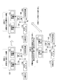
- FIG. 8 is an image diagram illustrating an example in which the power storage system 101 is operated on a weekly basis.
- the example shown in FIG. 8 shows the passage of time t on the horizontal axis, the voltage on the vertical axis, and the state of voltage transition between the voltage Va of the storage battery A121 and the voltage Vb of the storage battery B122.
- FIG. 8 conceptually shows a mode of charging the storage battery A121 and the storage battery B122, not the detailed change characteristics of the voltages of the storage battery A121 and the storage battery B122.
- FIG. 8 shows that a “bright” period in which the office room becomes brighter due to illumination or the incidence of external light and a “dark” period in which the room lighting turns off and dark at night etc.
- FIG. 2 conceptually shows a voltage change tendency between the storage battery A121 and the storage battery B122 on a weekly basis (Monday to Sunday).
- FIG. 8 the outline
- both the storage battery A121 and the storage battery B122 are in an uncharged state at the first time point (time t10) on the first day. Then, at time t10, the office room is brightened by illumination and external light, and power supply from the solar battery 110 to the storage battery A121 is started after time t10. Subsequently, when the voltage Va of the storage battery A121 gradually increases and reaches the time t11, and the voltage Va of the storage battery A121 becomes the voltage Va1, power supply to the storage battery B122 is started, and the voltage Vb of the storage battery B122 starts to increase.
- the power supply to the storage battery A121 and the storage battery B122 is continued from time t11 to time t12, that is, until the office lighting is turned off at time t12 and the “dark” period starts, and at time t12, the storage battery A121 is turned on.
- the voltage Va rises to the voltage Va2
- the voltage of the storage battery B122 rises to the voltage Vb1.
- the storage battery A121 is set so that the voltage Va1 can be fed to the external load device 200 and the external load device 200 can be continuously driven. That is, the charging capacity of the storage battery A121 is set so that the external load device 200 can be driven during a “dark” period in which the office lighting is turned off and darkens.
- the power supply to the storage battery A121 and the power supply to the storage battery B122 are performed during the “light” period, and the power is supplied from the storage battery A121 to the external load device 200 during the “dark” period. While being performed, power supply to the storage battery B122 is stopped.
- the “dark” period from the time t52 on the fifth day the period from the time t52 to the time t61 on the fifth day, the period from the time t61 to the time t71 on the sixth day, which is a holiday, and the holiday.
- the period from the time t71 on the seventh day to the time t72 is a “dark” period.
- power is supplied to the external load device 200 from both the storage battery A121 and the storage battery B122.
- the voltage Va of the storage battery A121 is equal to the voltage drop (for example, about 0.3 V) due to the semiconductor element constituting the switch SW1 of the switch unit 140, than the voltage of the storage battery B122. Also gets higher. Conversely, when power is supplied from the storage battery B122 to the power supply line DCL1, the voltage Va of the storage battery A121 is lower than the voltage Vb of the storage battery B122 by the voltage drop due to the semiconductor elements that constitute the switch SW1.
- the switch SW1 of the switch unit 140 is in the ON state, if the voltage Va of the storage battery A121 is higher than the voltage of the storage battery B122, the charge of the storage battery A121 is preferentially supplied to the external load device 200. Become. And if the electric charge accumulate
- FIG. 9 is a configuration diagram illustrating a modified example of the power storage system 101.
- the power storage system 101A illustrated in FIG. 9 is different from the power storage system 101 illustrated in FIG. 3 in that it includes a switching unit 170 (third switching unit) and a switch unit 180 (third switch unit).
- voltage detection unit 150 outputs detection signal Vf of voltage Va of storage battery A ⁇ b> 121 to switching unit 160 and also outputs to switching unit 170.
- the switch unit 180 has one terminal a connected to the power supply line DCL1 and the other terminal b connected to the external load device 200 via the power supply line DCL10.
- the switch unit 180 turns on or off the internal switch SW2 in accordance with the instruction content of the control signal CNT2 input from the switching unit 170, thereby electrically connecting the power supply line DCL1 and the power supply line DCL10. Switch between state and disconnected state. That is, by turning on the switch SW2, the power supply line DCL1 and the power supply line DCL10 are connected, and power is supplied from the power storage system 101A to the external load device 200.
- the switching unit 170 includes a comparator 171.
- the comparator 171 compares a predetermined reference voltage RefL generated by a reference voltage generation circuit (not shown) with the detection signal Vf of the voltage Va of the storage battery A121 input from the voltage detection unit 150.
- the reference voltage RefL corresponds to the drivable voltage VL (third threshold voltage) of the external load device 200, and determines whether or not the voltage Va of the storage battery A121 exceeds the voltage VL that can drive the external load device 200. Used when.
- the switching unit 170 outputs the control signal CNT2 toward the switch unit 180 in accordance with the comparison result in the comparator 171.
- the control signal CNT2 controls ON / OFF of the switch SW2 of the switch unit 180.
- the switch unit 180 opens and closes the switch SW2 based on the instruction content of the control signal CNT2.
- Switching unit 170 turns off switch SW2 of switch unit 180 when voltage Va of storage battery A121 is equal to or lower than voltage VL. Thereby, the power supply line DCL1 and the power supply line DCL10 are electrically disconnected, and the power of the power storage system 101A is prevented from being supplied to the external load device 200.
- the switching unit 170 turns on the switch SW2 when the voltage Va of the storage battery A121 exceeds the voltage VL. Thereby, the feeder line DCL1 and the feeder line DCL10 are connected, and the power of the power storage system 101A is supplied to the external load device 200. Accordingly, the power storage system 101A can supply power to the external load device 200 only when the voltage according to the input power supply specification (input voltage range) of the external load device 200 can be supplied.
- the storage battery A121 and the storage battery B122 are used.
- a third storage battery C (not shown) having a capacity larger than that of the storage battery B122 may be further provided.
- the storage battery C is also fed.
- the storage battery C can be used as an emergency battery or a storage battery corresponding to long periods, such as a monthly unit.
- the power storage system 101 includes the storage battery A121 (first storage battery), the storage battery B122 (second storage battery), the switch unit 140, and the switching unit 160.
- the storage battery A121 is supplied with power generated by the solar battery.
- the storage battery B122 has a larger capacity than the storage battery A121.
- the switch unit 140 switches between an electrical connection state and a disconnection state between the storage battery A121 and the storage battery B122.
- the switching unit 160 compares the voltage Va of the storage battery A121 with the voltage V1 (second threshold voltage), and controls the switch unit 140 according to the comparison result.
- the switching unit 160 switches the storage battery A121 and the storage battery B122 to a disconnected state when the voltage Va of the storage battery A121 is equal to or lower than the voltage V1, so that the generated power of the solar battery 110 is fed only to the storage battery A121. 140 is controlled. Further, the switching unit 160 connects the storage battery A121 and the storage battery B122 when the voltage of the storage battery A121 exceeds the voltage V1, and switches the switch unit 140 so that power is supplied from the storage battery A121 to the storage battery B122. Control.
- the electrical storage system 101 two types of storage batteries A121 and B122 having different capacities and the switch unit 140 are used. Then, the first storage battery A121 is preferentially supplied with power up to the voltage VL that can drive the external load device 200 (more precisely, the voltage V1 that enables power supply to the storage battery B122). When the voltage Va of the storage battery A121 exceeds the voltage V1, power is supplied from the storage battery A121 to the storage battery B122. Thereby, even when a large capacity storage battery is used, the output voltage of the power storage system 101 can be quickly raised. For this reason, the electrical storage system 101 can start the external load apparatus 200 early.
- FIG. 10 is a configuration diagram illustrating a configuration example of the power storage system 102.
- the power storage system 102 shown in FIG. 10 differs from the power storage system 101 shown in FIG. 3 in the following points.
- the power storage system 102 does not include the switch unit 140 illustrated in FIG. 3 but includes a switch unit 141 (first switch unit).
- the power storage device 120 includes a single storage battery 123.
- the comparator 191 of the switching unit 190 compares the detection signal Vf of the voltage Va of the storage battery A121 with a predetermined reference voltage Refm output from a reference voltage generation circuit (not shown).
- the contact c is connected to the solar cell 110 via the feed line DCL0, the contact a is connected to the feed line DCL1, and the contact b is connected to the DC / DC converter 130 via the feed line DCL3.
- Other configurations are the same as those of the power storage system 101 shown in FIG. For this reason, the same code
- a general DC / DC converter when charging from a low voltage state in which the voltage of the storage battery 123 is close to 0 V (zero volts), a general DC / DC converter can boost the voltage only with very low efficiency. Conversion loss increases. Such a state is called a start-up mode or a cold start mode, and becomes a big problem when storing weak power such as energy harvest. That is, the DC / DC converter 130 can perform a high-efficiency boosting operation called main boost only after the storage battery 123 is charged to a predetermined voltage.
- the conversion efficiency of the DC / DC converter 130 is about 10 to 40% in the startup mode and the cold start mode, which are modes with low conversion efficiency, and 70 to 90% in the main boost mode, which is a mode with high conversion efficiency.
- the voltage Va of the storage battery 123 at which the conversion efficiency in the DC / DC converter 130 is equal to or higher than a predetermined value is referred to as a main boost voltage Vm.
- the main boost voltage Vm that is, the voltage at which the DC / DC converter 130 is in the main boost mode is preferably the voltage of the storage battery 123 at which the conversion efficiency of the DC / DC converter 130 is 70% or more.
- the comparator 191 of the switching unit 190 compares the detection signal Vf of the voltage Va of the storage battery 123 with a predetermined reference voltage Refm, and the voltage Va of the storage battery 123 exceeds the main boost voltage Vm. It is determined whether or not.
- the reference voltage Refm corresponds to the voltage Vm of the storage battery 123, and whether or not the value of the voltage Va of the storage battery 123 exceeds a predetermined voltage Vc (first threshold voltage) that is equal to or higher than the main boost voltage Vm. It is used when judging.
- the voltage Vm that can be main boosted and the predetermined voltage Vc in the present embodiment is 1.8 V
- the predetermined voltage Vc (first threshold voltage) is 2. It is mentioned that it is 0V.
- the switching unit 190 causes the contact point a and the contact point c of the switch SW3 to be electrically connected so that the solar battery 110 directly supplies power to the storage battery 123.
- the predetermined voltage Vc (first threshold) may be set so that power is supplied to the DC / DC converter 130 after the DC / DC converter 130 enters the main boost mode.
- the threshold value Vc may be equal to the voltage Vm at which the DC / DC converter 130 enters the main boost mode.
- FIG. 11 is an explanatory diagram showing a mode of a charging operation for the storage battery 123.
- the switching unit 190 makes the contact a and the contact c of the switch SW3 of the switch unit 141 conductive until the voltage Va of the storage battery 123 reaches a predetermined voltage Vc. Then, the current Ia is allowed to flow from the solar battery 110 to the storage battery 123 to directly supply power.
- the switching unit 190 conducts the contact b and the contact c of the switch SW3 of the switch unit 141 so that power is supplied from the solar cell 110 to the DC / DC converter 130. Done. Further, power is supplied by flowing a current Ib from the DC / DC converter 130 to the storage battery 123.
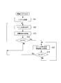
- FIG. 12 is a flowchart showing a flow of processing in the power storage system 102, and shows a flow of operation in the power storage system 102 described above.
- the flow of the process will be described with reference to FIG. First, it is assumed that the storage battery 123 is in an uncharged state.
- the switching unit 190 first sends a control signal CNT3 to the switch unit 140 to make the contact a and the contact c of the switch SW3 of the switch unit 141 conductive. b and contact c are made non-conductive (step S101). Thereby, the switching part 190 starts the direct electric power feeding from the solar cell 110 to the storage battery 123 (step S102).
- step S103 when it determines with the voltage Va of the storage battery 123 not exceeding the voltage Vc (step S103: No), it returns to the process of step S101.
- the switching unit 190 makes the contact a and the contact c of the switch SW3 of the switch unit 141 conductive and makes the contact b and contact c non-conductive, and continues the direct power supply from the solar battery 110 to the storage battery 123. .
- step S104 the switching unit 190 makes the contact a and the contact c of the switch SW3 of the switch unit 141 non-conductive, and makes the contact b and the contact c conductive (step S104). Thereby, the switching unit 190 supplies power to the storage battery 123 from the DC / DC converter 130 (step S105). Subsequently, the switching unit 190 returns to the process of step S103 and starts the process from step S103 again.
- the power storage system 102 supplies power directly from the solar battery 110 to the storage battery 123 until the voltage Va of the storage battery 123 reaches the predetermined voltage Vc.
- the voltage Va of the storage battery 123 exceeds the predetermined voltage Vc
- power can be supplied from the solar battery 110 to the storage battery 123 via the DC / DC converter 130. That is, in the power storage system 101A, when power is supplied to the storage battery 123 in a state where the charging voltage is low, power can be supplied without being affected by conversion loss at the time of voltage boost by the DC / DC converter. For this reason, in the state where the voltage Va charged in the storage battery 123 is low, the storage time in the storage battery 123 can be shortened.
- the power storage system 102 it is determined whether to supply power to the storage battery 123 via the DC / DC converter 130 only from the voltage Va of the storage battery 123.
- a low illuminance dye-sensitized solar cell for low illuminance is used as the storage battery 123, and the generated power is small.
- the DC / DC converter 130 that is electrically connected to the storage battery 123 is in a mode of low conversion efficiency until the voltage Va of the storage battery 123 becomes equal to or higher than the voltage Vm.
- the DC / DC converter 130 enters the main boost mode with high conversion efficiency. Therefore, the power storage system 102 is particularly effective in an environment with a predetermined illuminance or less.
- the power storage system 102 includes the storage battery 123, the DC / DC converter 130, the switch unit 141, and the switching unit 190.
- the storage battery 123 is supplied with power generated by the solar battery 110.
- the DC / DC converter 130 boosts the output voltage of the solar battery 110 to a predetermined voltage.
- the switch unit 141 switches whether the output voltage of the solar battery 110 is directly supplied to the storage battery 123 or is supplied via the DC / DC converter 130.
- the switching unit 190 compares the voltage of the storage battery 123 with the voltage Vc of the first threshold value, The switch unit 141 is controlled according to the comparison result. Further, the switching unit 190 controls the switch unit 141 to directly supply power from the solar cell 110 to the storage battery 123 when the voltage of the storage battery 123 is equal to or lower than the first threshold voltage Vc. Furthermore, the switching unit 190 controls the switch unit 141 to supply power to the storage battery 123 from the solar battery 110 via the DC / DC converter 130 when the voltage of the storage battery 123 exceeds the first threshold voltage Vc. To do.
- a switch unit 141 that switches between supplying power directly from the solar battery 110 to the storage battery 123 or supplying power via the DC / DC converter 130 is provided. Then, the switching unit 190 determines whether or not the voltage Va of the storage battery 123 exceeds the predetermined voltage Vc. When the voltage Va of the storage battery 123 is equal to or lower than the predetermined voltage Vc, the switching unit 190 directly transfers from the solar battery 110 to the storage battery 123. The switch unit 141 is controlled to supply power. In addition, the switching unit 190 controls the switch unit 141 to supply power to the storage battery 123 from the solar battery 110 via the DC / DC converter 130 when the voltage Va of the storage battery 123 exceeds the predetermined voltage Vc.
- the electrical storage system 102 in the state where the voltage Va of the storage battery 123 is low, power can be directly supplied from the solar battery 110 to the storage battery 123 without being affected by the conversion loss at the time of boosting of the DC / DC converter 130.
- the storage time for the storage battery 123 can be shortened when the voltage Va of the storage battery 123 is low. Therefore, the voltage of the storage battery 123 can be raised quickly.
- FIG. 13 is a configuration diagram illustrating a configuration example of the power storage system 103.
- the power storage system 103 illustrated in FIG. 13 differs from the power storage system 101 illustrated in FIG. 3 only in that it further includes a switch unit 141 (first switch unit) and a switching unit 190 (first switching unit).
- Other configurations are the same as those of the power storage system 101 shown in FIG. For this reason, the same code
- the switching unit 160 switches the switch SW1 of the switch unit 140 as in the power storage system 101. Is turned off to supply power only to the storage battery A121.
- the switching unit 190 makes the contact a and the contact c of the switch SW3 of the switch unit 141 conductive and makes the contact b and the contact c non-conductive. That is, in the power storage system 103, when the storage battery A121 is not charged or the voltage Va of the storage battery A121 is low, power is directly supplied from the solar battery 110 to the storage battery A121 without passing through the DC / DC converter 130.
- the switching unit 190 is connected to the contact b of the switch SW3 of the switch unit 141.
- c is made conductive (contact point a and contact point c are made non-conductive), and power is supplied to storage battery A121 via DC / DC converter 130.
- the power storage system 103 at the start of charging, first, only the storage battery A121 having a small capacity is preferentially supplied with power. Further, while the voltage Va of the storage battery A121 is lower than the voltage Vc of the main boost, power is directly supplied from the solar battery 110 to the storage battery A121 without passing through the DC / DC converter 130. Thereby, in the electrical storage system 103, while being able to select and supply electric power to storage battery A121 with a small capacity, it is possible to supply electric power to storage battery A121 without being affected by conversion loss during boosting in the DC / DC converter. For this reason, the voltage Va of the storage battery A121 can be raised quickly.
- the power storage system 103 may further include a switching unit 170 and a switch unit 180 as shown in FIG. 9 (power storage system 101A).
Landscapes
- Engineering & Computer Science (AREA)
- Power Engineering (AREA)
- Chemical & Material Sciences (AREA)
- Chemical Kinetics & Catalysis (AREA)
- Electrochemistry (AREA)
- General Chemical & Material Sciences (AREA)
- Business, Economics & Management (AREA)
- Emergency Management (AREA)
- Charge And Discharge Circuits For Batteries Or The Like (AREA)
- Secondary Cells (AREA)
- Computer Networks & Wireless Communication (AREA)
- Life Sciences & Earth Sciences (AREA)
- Sustainable Development (AREA)
- Sustainable Energy (AREA)
Abstract
Description
本願は、2013年12月27日に、日本に出願された特願2013-272146号に基づき優先権を主張し、その内容をここに援用する。
なお、特許文献1には、電力需要量に基づいて太陽電池に要求される適正発電量を求め、この要求される発電量に応じて、太陽電池の発電量を調整する発電システムが開示されている。
また、特許文献2及び3には、発電電圧の大きな屋外用の太陽電池において、太陽電池の発電電圧の電圧が蓄電池の電圧よりも大きい場合には、昇圧コンバータを介さずに蓄電池に給電して、昇圧コンバータでの変換ロスを低減することが開示されております。
特許文献4には、色素増感型太陽電池の発電電力を、レギュレータ回路や昇圧回路等によって安定化してから蓄電池に給電することが開示されている。
すなわち、発電素子を入力に用いた場合、その間放電圧以上の電圧に蓄電することができないために、通常、DC/DCコンバータ装置などの昇圧コンバータを用いることになる。しかしながら、蓄電池の電圧が低い状態では昇圧コンバータにおける電圧昇圧時の変換ロスが大きくなり、蓄電池の蓄電に多くの時間がかかってしまうという問題がある。
上記特許文献1~4に記載の発電システムは、上記問題に対応できていない。特に、特許文献2及び3では、発電電圧が大きな屋外用の太陽電池が用いられており、蓄電池の電圧が低い状態を考慮する必要がない。
上記態様に係る蓄電システムにおいては、発電素子から蓄電池に直接給電するか、DC/DCコンバータを介して給電するかを切り換えるスイッチ部を設ける。そして、切換部は、蓄電池の電圧が所定の電圧である第1閾値の電圧を超えているか否かを判定し、蓄電池の電圧が第1閾値の電圧以下の場合、発電素子から蓄電池に直接給電を行うようにスイッチ部を制御する。また、切換部は、蓄電池の電圧が第1閾値の電圧を超えている場合に、DC/DCコンバータを介して蓄電池に充電を行うようにスイッチ部を制御する。
さらに、上記態様に係る蓄電システムにおいて、DC/DCコンバータがメインブーストモードになる蓄電池の電圧以上の電圧が第1閾値であり、蓄電池の電圧が第1閾値の電圧以下の場合に発電素子から蓄電池に直接給電を行う。そして、蓄電池の電圧が上昇し、第1閾値の電圧を超えた場合、上記態様に係る蓄電システムは、DC/DCコンバータを介して蓄電池に給電を行う。
これにより、上記態様に係る蓄電システムでは、所定の照度以下の環境において低照度色素増感発電素子から出力される発生電力が小さく、蓄電池の電圧が低い場合でも、DC/DCコンバータによる電圧昇圧時の変換ロスに影響されることなく、蓄電池の電圧を早く立ち上げることができる。
これにより、容量が小さい蓄電池のみに発電素子が接続されているので、少ない電力で、第1闘値以上の電圧にすることが可能であり、早期にメインブーストモードにすることができる。
上記態様に係る蓄電システムにおいては、容量の異なる2種類の蓄電池を用いる、それぞれの蓄電池から外部負荷装置に電力を供給できる。そして、第1切換部は、第1蓄電池に充電される電圧が第2閾値の電圧になるまで、この第1蓄電池だけに発電素子の発電電力が給電されるように第2スイッチ部を制御する。そして、第1蓄電池の電圧が所定の電圧である第2閾値の電圧を超えた場合に、第2切換部は、第1蓄電池から第2蓄電池へ給電が行われるように第2スイッチ部を制御する。
これにより、蓄電システムは、大きな容量の蓄電池を用いた場合においても、外部負荷装置に給電する出力電圧を早く立ち上げることができる。特に、第1蓄電池が外部負荷装置に接続されているため、容量の大きな第2蓄電池が充電される前でも外部負荷装置に供給する出力電圧を立ち上げることができる。
上記態様に係る蓄電システムにおいては、第1蓄電池及び第2蓄電池と、外部負荷装置との間の電気的な接続状態及び切断状態を切り替える第3スイッチ部を設ける。そして、第3切換部は、第1蓄電池の電圧が第3閾値の電圧よりも高い場合に、第3スイッチ部を接続状態にして蓄電システムから外部負荷装置に給電を行う。また、第3切換部は、第1蓄電池の電圧が第3閾値の電圧よりも低い場合に、第3スイッチ部を切断状態にして蓄電システムから外部負荷装置を切り離す。
これにより、蓄電システムは、蓄電装置を初期充電する場合等、第1蓄電池の電圧が低い状態の場合に、外部負荷装置への給電を停止して無駄な電力消費を抑えることにより、第1蓄電池への充電を早めることができる。
これにより、蓄電システムは、外部負荷装置に給電を行う場合に、外部負荷装置を確実に動作させることができる。
上記態様に係る蓄電システムにおいて、第2切換部は、第1蓄電池の電圧が第2閾値の電圧を超えたことを検出した場合に、第1蓄電池と第2蓄電池との間を接続する。その後、第1蓄電池から第2蓄電池に給電が行われることにより第1蓄電池の電圧が低下する。そして、第2切換部は、第1蓄電池の電圧が、第1閾値の電圧から所定の電圧分だけ低く、前記第1の闘値よりも所定の電圧だけ高い第4閾値の電圧以下に低下したことを検出した場合に、第1蓄電池と前記第2蓄電池との間の接続を開放切断する。つまり、第2切換部は、ヒステリシス特性を持って用いて第2スイッチ部の開閉を制御する。
これにより、蓄電システムは、第1蓄電池から第2蓄電池へ給電を行うことができるとともに、第1蓄電池の電圧が第1闘値以下の電圧に低下しないようにすることができ、DC/DCコンバータをコールドスタートモードになりにくくすることができる。
これにより、上記態様に係る蓄電システムにおいて、発電素子は、必要とされる電圧を出力することができる。
これにより、蓄電システムは、低照度用の太陽電池から出力される電力を大きな容量の蓄電池を用いて蓄電する場合においても、外部出力する出力電圧を早く立ち上げることができる。
これにより、上記態様に係る蓄電システムでは、所定の照度以下の環境において低照度色素増感発電素子から出力される発生電力が小さいことにより、蓄電池の電圧が低い状態でも、蓄電池への蓄電時間を早めることができる。
図1は、本発明の実施形態に係る蓄電システムが用いられる環境監視システムの概略構成を示す構成図である。図1に示すように環境監視システム1は、環境発電を行う発電素子の発電電力を蓄電池に蓄積する蓄電システム100と、蓄電システム100から給電される外部負荷装置200とで構成される。外部負荷装置200としては、例えば、配線や電池交換なしで動作するワイヤレスセンサとして機能する環境モニタ装置210等が挙げられる。
環境モニタ装置210は、オフィス等の室内の温度を測定する温度センサ211と、室内の湿度を測定する湿度センサ212とを備える。環境モニタ装置210は、温度センサ211により測定した室内温度の情報と、湿度センサ212により測定した室内湿度の情報とを、無線通信ユニット213により、周期的に外部の監視システム300に向けて無線送信する。
図2A及び2Bに示す太陽電池110は、4つの太陽電池セルを直列に接続した例であるが、直列に接続される太陽電池セルの個数は限定されない。太陽電池セルの個数は、DC/DCコンバータ130に向けて出力される電圧が、DC/DCコンバータ130において所定の効率以上で昇圧動作が行える電圧になるように選択される。例えば、太陽電池セルが低照度色素増感太陽電池である場合、直列に接続される太陽電池セルの個数を、例えば、最低3個以上にすることが望ましい。
本実施形態に係る蓄電システムでは、上記問題を解決するために、容量の異なる2種類の蓄電池A121及び蓄電池B122と、スイッチング機構としてのスイッチ部140とを用いる。
太陽電池110は、図2A及び2Bに示した低照度用の太陽電池である。蓄電装置120は、エナジーハーベストの用途に対応する二次電池やコンデンサ等で構成され、容量の小さな蓄電池A121と、容量の大きな蓄電池B122と、で構成されている。
また、蓄電池B(第2蓄電池)122の容量の大きさは、外部負荷装置200の負荷容量と、外部負荷装置200を連続して駆動できる時間とに応じて設定される。例えば、蓄電池A121に対する蓄電池B122の容量比率は、数倍から数十倍程度に設定される。
DC/DCコンバータ130の出力側は、給電線DCL1を介して、蓄電池A121に接続されるとともに、スイッチ部140の一方の端子aに接続されている。スイッチ部140の他方の端子bは、給電線DCL2を介して、蓄電池B122に接続されている。
なお、図3では、スイッチ部140として、機械式接点を用いたスイッチSW1で構成される例を示している。しかしながら、実際には、スイッチSW1は、MOSFET(Metal Oxide Semiconductor Field Effect Transistor)やIGBT(Insulated Gate Bipolar Transistor)等の半導体スイッチング素子を用いた半導体スイッチを含んでいる。
つまり、切換部160は、蓄電池A121の電圧Vaが電圧V1よりも低い場合に、制御信号CNT1によりスイッチ部140のスイッチSW1をOFFにして蓄電池A121と蓄電池B122とを電気的に切り離す。これにより、太陽電池110の発電電力が、DC/DCコンバータ130を介して、蓄電池A121のみに給電されるようになる。
なお、蓄電池B122に給電を行う際には、DC/DCコンバータ130の出力電力が小さいため、主に蓄電池A121が蓄電池B122へ給電を行う。このため、以下の説明では、蓄電池B122への給電は、蓄電池A121から行われるものとして説明する。
従って、切換部160は、蓄電池A121の電圧Vaが電圧V1を超えていることを検出して、一旦スイッチSW1をONにする制御信号CNT1を出力した後、電圧Vaが電圧V1’(第4閾値の電圧)に低下するまで、SW1をONにする制御信号CNT1を出力し続ける。
なお、電圧V1’は、電圧V1よりも所定の電圧だけ低く、外部負荷装置200の駆動可能電圧VLよりも所定の電圧だけ高く設定される(V1’>VL)。つまり、電圧V1も外部負荷装置200の駆動可能電圧VLよりも高い電圧に設定される(V1>V1’>VL)。これにより、DC/DCコンバータをコールドスタートモードになりにくくすることができる。
以下、図5を参照して、蓄電池A121及び蓄電池B122への充電動作の態様について説明する。
蓄電装置120への給電を最初に開始する場合、つまり、蓄電池A121と蓄電池B122との両方が未充電の場合は、まず、状態(1)に示すように、スイッチ部140のスイッチSW1をOFFにする。それにより、DC/DCコンバータ130から蓄電池A121にのみ充電電流Iaを流し、蓄電池A121が優先して充電される。
図6の時刻t0において、太陽電池110からDC/DCコンバータ130を介して蓄電装置120の充電が開始されるものとする。時刻t0における充電開始時には、図5の状態(1)に示すように、切換部160は、スイッチ部140のスイッチSW1をOFFにして、蓄電池A121のみへの給電を開始する。
なお、外部負荷装置200は、例えば、前述した環境モニタ装置210であり、環境モニタ装置210は、周期的に温度情報や湿度情報等を外部に無線送信する。
このため、蓄電池A121の電圧Vaは、図6の破線で囲んだ部分Eで拡大して示すように、電圧V1と電圧V1’の間で変動する電圧となる。
そして、時刻t2以降、蓄電池B122への充電が進み、蓄電池B122の電圧Vbが、次第に上昇していく。
なお、蓄電池A121及び蓄電池B122の電圧が電圧VHになると、DC/DCコンバータ130は、蓄電池A121及び蓄電池B122への過充電を防ぐために、出力を停止して、蓄電池A121及び蓄電池B122への給電を停止する。
以下、図7を参照して、その処理の流れについて説明する。
まず、蓄電池A121及び蓄電池B122が未充電の状態にあるとする。そして、蓄電システム101が起動すると(ステップS11)、切換部160は、スイッチ部140のスイッチSW1をOFFにする(ステップS12)。そして、太陽電池110は、DC/DCコンバータ130を介して、蓄電池A121のみに給電を開始する(ステップS13)。
そして、ステップS14において、蓄電池A121の電圧Vaが電圧V1を超えていると判定された場合(ステップS14:Yes)、ステップS15の処理に移行する。ステップS15では、切換部160が、スイッチ部140のスイッチSW1をONにして、蓄電池A121から蓄電池B122への給電が開始される。蓄電池A121から蓄電池B122へ給電を行うことにより、蓄電池A121の電圧Vaが下降する。
そして、ステップS16において、蓄電池A121の電圧Vaが電圧V1’よりも低下していないと判定された場合(ステップS16:No)、切換部160は、ステップS15の処理に戻り、蓄電池A121から蓄電池B122への給電を継続する。
一方、ステップS16において、蓄電池A121の電圧Vaが電圧V1’よりも低下している判定された場合(ステップS16:Yes)、切換部190は、ステップS12の処理に戻り、スイッチ部140のスイッチSW1をOFFにして、再び、蓄電池A121のみへの給電を開始する。
上記処理の流れにより、蓄電システム101は、大きな容量の蓄電池を用いた場合においても、外部負荷装置200に出力する電圧を早く立ち上げることができる。また、蓄電システム101では、外部負荷装置200を駆動させつつ、蓄電池B122への蓄電を進めることができる。
なお、図8は、蓄電池A121及び蓄電池B122の電圧の詳細な変化特性ではなく、蓄電池A121及び蓄電池B122に対する充電の態様を概念的に示している。つまり、図8は、オフィスの室内が照明や外部光の入射により明るくなる「明」の期間と、夜間等において室内の照明が消灯して暗くなる「暗」の期間とが一日単位で繰り返される場合の、週単位(月曜から日曜日)での蓄電池A121と蓄電池B122との電圧変化の傾向を概念的に示している。
以下、図8を参照して、蓄電池A121の電圧Vaと蓄電池B122の電圧Vbとの週単位での推移の概要について説明する。
続いて、蓄電池A121の電圧Vaが次第に増加し、時刻t11に至り、蓄電池A121の電圧Vaが電圧Va1になると、蓄電池B122への給電が開始され、蓄電池B122の電圧Vbが上昇し始める。
続いて、時刻t11から時刻t12まで、つまり、時刻t12においてオフィスの照明等が落とされ「暗」の期間に入るまで、蓄電池A121及び蓄電池B122への給電が継続され、時刻t12において、蓄電池A121の電圧Vaは、電圧Va2まで上昇し、蓄電池B122の電圧は、電圧Vb1まで上昇する。
なお、蓄電池A121の電圧Vaが、電圧Va1まで低下した状態においても、蓄電池A121が電圧Va1を外部負荷装置200に給電して、外部負荷装置200を連続して駆動できるように設定されている。つまり、蓄電池A121の充電容量は、オフィスの照明等が消されて暗くなる「暗」の期間、外部負荷装置200を駆動できるように設定されている。
このように、蓄電システム101では、「明」の期間に、蓄電池A121への給電と、蓄電池B122への給電とが行われ、「暗」の期間に、蓄電池A121から外部負荷装置200に給電が行われるとともに、蓄電池B122への給電が停止される。
そして、4日目の時刻t43以降、スイッチ部140のスイッチSW1が継続的にON状態になり、蓄電池A121の電圧と蓄電池B122の電圧は同じ電圧(Va≒Vb)で推移する。
以上説明したように、蓄電システム101を週単位で運用する場合、平日(1日目から5日目)に蓄電池B122の充電を行っておき、休日(6日目及び7日目)に、蓄電池B122に蓄積された電力を利用することができる。
図9に示す蓄電システム101Aは、切換部170(第3切換部)とスイッチ部180(第3スイッチ部)とを備えている点で図3に示す蓄電システム101と異なる。
図9において、電圧検出部150は、蓄電池A121の電圧Vaの検出信号Vfを切換部160に出力するとともに、切換部170にも出力する。
また、スイッチ部180は、一方の端子aが給電線DCL1に接続され、他方の端子bが、給電線DCL10を介して、外部負荷装置200に接続されている。
スイッチ部180は、切換部170から入力される制御信号CNT2の指示内容に応じて、内部のスイッチSW2をON又はOFFにすることにより、給電線DCL1と給電線DCL10との間の電気的な接続状態及び切断状態の切換を行う。つまり、スイッチSW2をONにすることにより、給電線DCL1と給電線DCL10とが接続され、蓄電システム101Aから外部負荷装置200に電力が供給される。
切換部170は、蓄電池A121の電圧Vaが電圧VL以下の場合に、スイッチ部180のスイッチSW2をOFFにする。それにより、給電線DCL1と給電線DCL10とが電気的に切り離され、蓄電システム101Aの電力が外部負荷装置200に供給されないようにする。
これにより、蓄電システム101Aは、外部負荷装置200の入力電源仕様(入力電圧範囲)に応じた電圧を供給できる場合にのみ、外部負荷装置200に給電を行うようにできる。
これにより、大きな容量の蓄電池を用いた場合においても、蓄電システム101の出力電圧を早く立ち上げることができる。このため、蓄電システム101は、外部負荷装置200を早く起動することができる。
図10に示す蓄電システム102は、図3に示す蓄電システム101と比較すると、以下の点が異なる。まず、蓄電システム102は、図3に示すスイッチ部140を含まず、スイッチ部141(第1スイッチ部)を備える。また、蓄電装置120が単体の蓄電池123で構成される。また、切換部190(第1切換部)の比較器191が、蓄電池A121の電圧Vaの検出信号Vfを、不図示の基準電圧生成回路から出力される所定の基準電圧Refmと比較する。そして、スイッチ部141は、接点cが給電線DCL0を介して太陽電池110に接続され、接点aが給電線DCL1に接続され、接点bが給電線DCL3を介してDC/DCコンバータ130に接続されている。他の構成は、図3に示す蓄電システム101と同様である。このため、同一の構成部分には同一の符号を付し、重複する説明は省略する。
なお、以下の説明において、DC/DCコンバータ130における変換効率が所定の値以上になる蓄電池123の電圧Vaをメインブーストの電圧Vmと呼ぶ。また、メインブーストの電圧Vm、つまりDC/DCコンバータ130がメインブーストモードになる電圧としては、DC/DCコンバータ130の変換効率が70%以上となる蓄電池123の電圧であることが好ましい。
そして、蓄電池123の電圧Vaが所定の電圧Vc以下の場合、切換部190は、スイッチSW3の接点aと接点cとを導通させて、太陽電池110から蓄電池123に直接給電を行わせる。また、蓄電池123の電圧が所定の電圧Vcを超えている場合、切換部190は、スイッチSW3の接点bと接点cとを導通させて、DC/DCコンバータ130を介して蓄電池123に給電を行わせる。なお、所定の電圧Vc(第1閾値)は、DC/DCコンバータ130がメインブーストモードになった後に、DC/DCコンバータ130に給電されるように設定されればよく、所定の電圧(第1閾値)Vcと、DC/DCコンバータ130がメインブーストモードになる電圧Vmとが等しくてもよい。
図11の状態(1)に示すように、蓄電池123の電圧Vaが所定の電圧Vcになるまでは、切換部190は、スイッチ部141のスイッチSW3の接点aと接点cとを導通させる。そして、太陽電池110から蓄電池123に電流Iaを流して直接給電が行われる。その後、蓄電池123の電圧Vaが所定の電圧Vcになると、切換部190は、スイッチ部141のスイッチSW3の接点bと接点cとを導通させて、太陽電池110からDC/DCコンバータ130に給電が行われる。さらに、DC/DCコンバータ130から蓄電池123に電流Ibを流して給電が行われる。
まず、蓄電池123が未充電の状態にあるとする。そして、蓄電システム102が起動すると(ステップS100)、切換部190は、最初に、スイッチ部140に制御信号CNT3を送り、スイッチ部141のスイッチSW3の接点aと接点cとを導通にして、接点bと接点cとを非導通にする(ステップS101)。これにより、切換部190は、太陽電池110から蓄電池123への直接給電を開始させる(ステップS102)。
そして、ステップS103において、蓄電池123の電圧Vaが電圧Vcを超えていないと判定された場合(ステップS103:No)、ステップS101の処理に戻る。この場合、切換部190は、スイッチ部141のスイッチSW3の接点aと接点cとを導通にし、接点bと接点cとを非導通にして、太陽電池110から蓄電池123への直接給電を継続させる。
続いて、切換部190は、ステップS103の処理に戻り、再び、ステップS103からの処理を開始する。
特に、所定の照度以下の環境においては、蓄電池123として低照度用の低照度色素増感太陽電池が用いられ、発生電力が小さい。この場合、蓄電池123と導通するDC/DCコンバータ130は、蓄電池123の電圧Vaが電圧Vm以上になるまでは変換効率の低いモードになる。そして、蓄電池123の電圧が第1閾値の電圧Vm以上になると、DC/DCコンバータ130は変換効率が高いメインブーストモードになる。
従って、蓄電システム102は所定の照度以下の環境において特に有効である。
これにより、蓄電システム102では、蓄電池123の電圧Vaが低い状態において、DC/DCコンバータ130の昇圧時の変換ロスに影響されることなく、太陽電池110から蓄電池123に直接給電できる。このように、蓄電システム102では、蓄電池123の電圧Vaが低い状態において、蓄電池123への蓄電時間を早めることができる。従って、蓄電池123の電圧を早く立ち上げることができる。
図13に示す蓄電システム103は、図3に示す蓄電システム101と比較すると、スイッチ部141(第1スイッチ部)と切換部190(第1切換部)とをさらに備える点だけが異なる。他の構成は、図3に示す蓄電システム101と同様である。このため、同一の構成部分には同一の符号を付し、重複する説明は省略する。
また、同時に、蓄電システム102と同様にして、切換部190は、スイッチ部141のスイッチSW3の接点aと接点cとを導通させて、接点bと接点cとは非導通にさせる。つまり、蓄電システム103では、蓄電池A121が未充電、或いは、蓄電池A121の電圧Vaが低い場合に、DC/DCコンバータ130を介さずに、太陽電池110から蓄電池A121に直接給電する。
その後は、蓄電システム101と同様にして、蓄電池A121の電圧が外部負荷装置200を駆動可能な電圧VL(VL>Vc)に到達した場合に、外部負荷装置200に給電を開始し、蓄電池A121の電圧が電圧V1(第2閾値の電圧)(V1>VL>Vc)に到達した場合に、蓄電池A121から蓄電池B122への給電を開始する。
Claims (9)
- 環境発電を行う発電素子と、
前記発電素子の発電電力により給電される蓄電池と、
前記発電素子の出力電圧を所定の電圧に変換するDC/DCコンバータと、
前記発電素子の出力電圧を前記蓄電池に直接給電するか、又は、前記DC/DCコンバータを介して給電するかを切り換える第1スイッチ部と、
前記DC/DCコンバータがメインブーストモードになる前記蓄電池の電圧以上の電圧を第1閾値とした場合に、前記蓄電池の電圧と前記第1閾値の電圧とを比較し、その比較結果に応じて、前記スイッチ部を制御する第1切換部と、
を備え、
前記第1切換部は、前記蓄電池の電圧が前記第1閾値の電圧以下の場合に、前記発電素子から前記蓄電池へ直接給電を行うように前記第1スイッチ部を制御し、
前記第1切換部は、前記蓄電池の電圧が前記第1閾値の電圧を超えている場合に、前記発電素子から前記DC/DCコンバータを介して前記蓄電池へ給電を行うように前記第1スイッチ部を制御する蓄電システム。 - 前記蓄電池は、第1蓄電池と、前記第1蓄電池よりも容量が大きい第2蓄電池で構成され、
第2閾値を前記第1閾値より大きい値とした場合、前記蓄電池の電圧が前記第2閾値以下では、前記第1蓄電池のみに前記発電素子から給電される請求項1に記載の蓄電システム。 - 前記第1蓄電池と前記第2蓄電池との間の電気的な接続状態及び切断状態の切換を行う第2スイッチ部と、
前記第1蓄電池の電圧と前記第2閾値の電圧とを比較し、その比較結果に応じて前記第2スイッチ部を制御する第2切換部と、
をさらに備え、
前記第1蓄電池と前記第2蓄電池とは、それぞれ外部負荷装置に電力を供給するように構成され、
前記第2閾値は、前記外部負荷装置を動作可能な電圧以上であり、
前記第2切換部は、前記第1蓄電池の電圧が前記第2閾値の電圧以下の場合に、前記第1蓄電池と前記第2蓄電池との間を切断状態にして、前記発電素子の発電電力が前記第1蓄電池のみに給電されるように前記第2スイッチ部を制御し、
前記第2切換部は、前記第1蓄電池の電圧が前記第2閾値の電圧を超えている場合に、前記第1蓄電池と前記第2蓄電池との間を接続状態にして、前記第1蓄電池から前記第2蓄電池へ給電が行われるように前記第2スイッチ部を制御する
請求項2に記載の蓄電システム。 - 前記第1蓄電池及び前記第2蓄電池と前記外部負荷装置との間の電気的な接続状態及び切断状態の切換を行う第3スイッチ部と、
前記第1蓄電池の電圧と第3閾値の電圧とを比較し、その比較結果に応じて、前記第3スイッチ部を制御する第3切換部と、
をさらに備え、
前記第1蓄電池の電圧が前記第3閾値の電圧よりも高い状態の場合、前記第3切換部は、前記第1蓄電池及び前記第2蓄電池と前記外部負荷装置との間が接続状態になるように前記第3スイッチ部を制御し、
前記第1蓄電池の電圧が前記第3閾値の電圧よりも低い状態の場合、前記第3切換部は、前記第1蓄電池及び前記第2蓄電池と前記外部負荷装置との間が切断状態になるように前記第3スイッチ部を制御する
ことを特徴とする請求項3に記載の蓄電システム。 - 前記第3閾値の電圧は、前記外部負荷装置が動作可能な動作電圧よりも所定の電圧分だけ高くかつ前記第2閾値の電圧よりも低く設定される
請求項4に記載の蓄電システム。 - 前記第2切換部は、ヒステリシス特性を有しており、前記ヒステリシス特性を用いて前記第1蓄電池の電圧と前記第2閾値の電圧とを比較し、
前記第2切換部は、前記第1蓄電池の電圧が前記第2閾値の電圧を超えている場合に、前記第1蓄電池と前記第2蓄電池との間が接続状態になるように前記第2スイッチ部を制御し、
前記第2切換部は、前記第1蓄電池と前記第2蓄電池との間が接続状態で、かつ前記第1蓄電池の電圧が前記第2閾値の電圧よりも所定の電圧だけ低く、前記第1の闘値よりも所定の電圧だけ高い第4閾値の電圧以下に低下した場合に、前記第1蓄電池と前記第2蓄電池との間が切断状態になるように前記第2スイッチ部を制御する
請求項3から請求項5のいずれか一項に記載の蓄電システム。 - 前記発電素子は、発電素子セルを直列に接続して構成される請求項1から請求項6のいずれか一項に記載の蓄電システム。
- 前記発電素子は、所定の照度以下の環境において使用可能な低照度用の太陽電池である
ことを特徴とする請求項1から請求項7のいずれか一項に記載の蓄電システム。 - 環境発電を行う発電素子の発電電力により給電される蓄電池と、前記発電素子の出力電圧を所定の電圧に変換するDC/DCコンバータと、前記発電素子の出力電圧を前記蓄電池に直接給電するか、又は、前記DC/DCコンバータを介して給電するかを切り換えるスイッチ部と、前記DC/DCコンバータがメインブーストモードになる前記蓄電池の電圧以上の電圧を第1閾値とした場合に、前記蓄電池の電圧と前記第1閾値の電圧とを比較し、その比較結果に応じて、前記スイッチ部を制御する切換部と、を備える蓄電システムを準備し、
前記蓄電池の電圧が前記第1閾値の電圧以下の場合に、前記切換部が、前記発電素子から前記蓄電池へ直接給電を行うように前記スイッチ部を制御し、
前記蓄電池の電圧が前記第1閾値の電圧を超えている場合に、前記切換部が、前記発電素子から前記DC/DCコンバータを介して前記蓄電池へ給電を行うように前記スイッチ部を制御する、
ことを含む蓄電方法。
Priority Applications (4)
| Application Number | Priority Date | Filing Date | Title |
|---|---|---|---|
| US15/107,750 US10181748B2 (en) | 2013-12-27 | 2014-12-26 | Power storage system and power storage method |
| CN201480071077.6A CN105934827B (zh) | 2013-12-27 | 2014-12-26 | 蓄电系统以及蓄电方法 |
| JP2015555064A JP6186450B2 (ja) | 2013-12-27 | 2014-12-26 | 蓄電システム、及び蓄電方法 |
| EP14875875.8A EP3089312B1 (en) | 2013-12-27 | 2014-12-26 | Electricity storage system and electricity storage method |
Applications Claiming Priority (2)
| Application Number | Priority Date | Filing Date | Title |
|---|---|---|---|
| JP2013-272146 | 2013-12-27 | ||
| JP2013272146A JP5668132B1 (ja) | 2013-12-27 | 2013-12-27 | 蓄電システム、及び蓄電方法 |
Publications (1)
| Publication Number | Publication Date |
|---|---|
| WO2015099159A1 true WO2015099159A1 (ja) | 2015-07-02 |
Family
ID=52569521
Family Applications (1)
| Application Number | Title | Priority Date | Filing Date |
|---|---|---|---|
| PCT/JP2014/084646 Ceased WO2015099159A1 (ja) | 2013-12-27 | 2014-12-26 | 蓄電システム、及び蓄電方法 |
Country Status (5)
| Country | Link |
|---|---|
| US (1) | US10181748B2 (ja) |
| EP (1) | EP3089312B1 (ja) |
| JP (2) | JP5668132B1 (ja) |
| CN (1) | CN105934827B (ja) |
| WO (1) | WO2015099159A1 (ja) |
Cited By (3)
| Publication number | Priority date | Publication date | Assignee | Title |
|---|---|---|---|---|
| EP3419142A4 (en) * | 2016-02-16 | 2019-08-28 | Fujikura Ltd. | ENERGY STORAGE SYSTEM AND ENERGY STORAGE PROCESS |
| WO2019230355A1 (ja) * | 2018-05-31 | 2019-12-05 | パナソニック株式会社 | 無線給電センシングシステム |
| KR20220015402A (ko) * | 2019-05-29 | 2022-02-08 | 이-피스 에스.에이. | 에너지 하베스팅하고 재충전 가능한 에너지 저장 디바이스를 충전하기 위한 방법 및 디바이스 |
Families Citing this family (8)
| Publication number | Priority date | Publication date | Assignee | Title |
|---|---|---|---|---|
| WO2014184379A1 (en) | 2013-05-17 | 2014-11-20 | Exeger Sweden Ab | A dye-sensitized solar cell and a method for manufacturing the solar cell |
| US10964486B2 (en) * | 2013-05-17 | 2021-03-30 | Exeger Operations Ab | Dye-sensitized solar cell unit and a photovoltaic charger including the solar cell unit |
| US10551894B2 (en) * | 2016-11-03 | 2020-02-04 | Microsoft Technology Licensing, Llc | Dynamic power management in a hybrid dual battery system |
| CN108448603A (zh) * | 2018-04-08 | 2018-08-24 | 苏州南海道电子科技有限公司 | 一种新能源蓄电器 |
| DE102018110785A1 (de) * | 2018-05-04 | 2019-11-07 | Abb Schweiz Ag | Autonomes drahtloses Sensorgerät und zugehöriges Anlaufverfahren |
| MX2021000624A (es) * | 2018-07-16 | 2021-03-25 | Exeger Operations Ab | Una unidad de celda solar sensibilizada por colorante, un cargador fotovoltaico que incluye la unidad de celda solar sensibilizada por colorante y un metodo para la produccion de la unidad de celda solar. |
| DE102019204748A1 (de) * | 2019-04-03 | 2020-10-08 | Robert Bosch Gmbh | Energieversorgungsanordnung für ein Steuergerät eines Fahrzeugs |
| JP7780944B2 (ja) * | 2021-12-23 | 2025-12-05 | ミネベアミツミ株式会社 | 車両用電源装置及びドアラッチ装置 |
Citations (5)
| Publication number | Priority date | Publication date | Assignee | Title |
|---|---|---|---|---|
| JPS62154122A (ja) | 1985-12-27 | 1987-07-09 | Kyocera Corp | 太陽光発電装置における充電制御方式 |
| JP2004336974A (ja) * | 2003-05-12 | 2004-11-25 | Origin Electric Co Ltd | 電源装置 |
| JP2011211885A (ja) | 2010-03-11 | 2011-10-20 | Sanyo Electric Co Ltd | 蓄電システム |
| JP2012079322A (ja) | 2011-11-09 | 2012-04-19 | Panasonic Corp | 無線センサ装置 |
| JP2012108829A (ja) | 2010-11-19 | 2012-06-07 | Konica Minolta Business Technologies Inc | 発電システムおよび発電監視装置 |
Family Cites Families (21)
| Publication number | Priority date | Publication date | Assignee | Title |
|---|---|---|---|---|
| JPH08251832A (ja) * | 1995-03-06 | 1996-09-27 | Omron Corp | 太陽電池を用いた充電方法及び充電装置 |
| JP3820757B2 (ja) * | 1998-07-23 | 2006-09-13 | 日新電機株式会社 | 分散型電源設備 |
| DE10057113B4 (de) | 2000-11-16 | 2004-07-01 | K + G Pneumatik Gmbh | Energieversorgungsanordnung für Rauch- und Wärmeabzugsanlagen mit elektrischen Antrieben |
| JP2004208479A (ja) * | 2002-12-20 | 2004-07-22 | Kyokuto Giko Consultant:Kk | 新エネルギーハイブリッド電源システム及びその制御方法 |
| US7642753B2 (en) * | 2005-09-16 | 2010-01-05 | Motorola, Inc. | Apparatus and switching method for improving cycle-life and capacity of a battery pack |
| JP2007181278A (ja) * | 2005-12-27 | 2007-07-12 | Morioka Seiko Instruments Inc | 自立電源及び無線センサーネットワーク装置 |
| JP2008046751A (ja) | 2006-08-11 | 2008-02-28 | Toyota Motor Corp | 太陽光発電システム、車両、太陽光発電システムの制御方法、およびその制御方法をコンピュータに実行させるためのプログラムを記録したコンピュータ読取可能な記録媒体 |
| JP2009033892A (ja) * | 2007-07-27 | 2009-02-12 | Panasonic Corp | 独立電源システム |
| DE102008004675B3 (de) | 2007-10-12 | 2009-03-05 | Fraunhofer-Gesellschaft zur Förderung der angewandten Forschung e.V. | Steuerbare Umschaltvorrichtung für ein Solarmodul |
| CN101561105B (zh) * | 2008-04-17 | 2013-02-13 | 鸿富锦精密工业(深圳)有限公司 | 发光模组 |
| US20100000804A1 (en) * | 2008-07-02 | 2010-01-07 | Ming-Hsiang Yeh | Solar vehicle |
| CN201450012U (zh) * | 2009-08-05 | 2010-05-05 | 华南理工大学 | 应用于光伏电池最大功率跟踪的分段自适应爬山系统 |
| JP2011120449A (ja) | 2009-10-29 | 2011-06-16 | Sanyo Electric Co Ltd | 発電システム、制御装置および切替回路 |
| JP2011200096A (ja) * | 2010-02-26 | 2011-10-06 | Sanyo Electric Co Ltd | 蓄電システム |
| JP5691365B2 (ja) | 2010-10-07 | 2015-04-01 | ソニー株式会社 | 電力制御装置、電力制御方法、および給電システム |
| US20130099721A1 (en) * | 2011-10-21 | 2013-04-25 | Moneer Azzam | Combination energy storage system for solar, wind and other "non-dispatchable" energy sources serving variable loads in various conditions |
| US9515489B2 (en) | 2011-11-07 | 2016-12-06 | Global Link Co., Ltd. | Feed system to be used in residence such as multi-unit apartment complex |
| JP2013201099A (ja) * | 2012-03-26 | 2013-10-03 | Fujikura Ltd | 低照度用色素増感太陽電池 |
| WO2014162686A1 (ja) * | 2013-04-03 | 2014-10-09 | パナソニック株式会社 | バッテリーシステム |
| CN105103404A (zh) * | 2013-04-03 | 2015-11-25 | 株式会社自动网络技术研究所 | 控制装置、供电控制装置、充电控制方法、充电控制装置以及车辆用电源装置 |
| EP3089315A4 (en) * | 2013-12-27 | 2017-10-04 | Fujikura Ltd. | Electricity storage system and electricity storage method |
-
2013
- 2013-12-27 JP JP2013272146A patent/JP5668132B1/ja not_active Expired - Fee Related
-
2014
- 2014-12-26 EP EP14875875.8A patent/EP3089312B1/en not_active Not-in-force
- 2014-12-26 CN CN201480071077.6A patent/CN105934827B/zh not_active Expired - Fee Related
- 2014-12-26 WO PCT/JP2014/084646 patent/WO2015099159A1/ja not_active Ceased
- 2014-12-26 US US15/107,750 patent/US10181748B2/en active Active
- 2014-12-26 JP JP2015555064A patent/JP6186450B2/ja not_active Expired - Fee Related
Patent Citations (5)
| Publication number | Priority date | Publication date | Assignee | Title |
|---|---|---|---|---|
| JPS62154122A (ja) | 1985-12-27 | 1987-07-09 | Kyocera Corp | 太陽光発電装置における充電制御方式 |
| JP2004336974A (ja) * | 2003-05-12 | 2004-11-25 | Origin Electric Co Ltd | 電源装置 |
| JP2011211885A (ja) | 2010-03-11 | 2011-10-20 | Sanyo Electric Co Ltd | 蓄電システム |
| JP2012108829A (ja) | 2010-11-19 | 2012-06-07 | Konica Minolta Business Technologies Inc | 発電システムおよび発電監視装置 |
| JP2012079322A (ja) | 2011-11-09 | 2012-04-19 | Panasonic Corp | 無線センサ装置 |
Cited By (9)
| Publication number | Priority date | Publication date | Assignee | Title |
|---|---|---|---|---|
| EP3419142A4 (en) * | 2016-02-16 | 2019-08-28 | Fujikura Ltd. | ENERGY STORAGE SYSTEM AND ENERGY STORAGE PROCESS |
| WO2019230355A1 (ja) * | 2018-05-31 | 2019-12-05 | パナソニック株式会社 | 無線給電センシングシステム |
| JPWO2019230355A1 (ja) * | 2018-05-31 | 2021-06-10 | パナソニック株式会社 | 無線給電センシングシステム |
| US11146118B2 (en) | 2018-05-31 | 2021-10-12 | Panasonic Corporation | Wireless power supply sensing system |
| JP7177830B2 (ja) | 2018-05-31 | 2022-11-24 | パナソニックホールディングス株式会社 | 無線給電センシングシステム |
| KR20220015402A (ko) * | 2019-05-29 | 2022-02-08 | 이-피스 에스.에이. | 에너지 하베스팅하고 재충전 가능한 에너지 저장 디바이스를 충전하기 위한 방법 및 디바이스 |
| JP2022534033A (ja) * | 2019-05-29 | 2022-07-27 | イー-ピース エセ.ア. | エネルギーハーベスティング及び充電式エネルギー貯蔵デバイスの充電のための方法及びデバイス |
| JP7508126B2 (ja) | 2019-05-29 | 2024-07-01 | イー-ピース エセ.ア. | エネルギーハーベスティング及び充電式エネルギー貯蔵デバイスの充電のための方法及びデバイス |
| KR102906675B1 (ko) | 2019-05-29 | 2025-12-30 | 이-피스 | 에너지 하베스팅하고 재충전 가능한 에너지 저장 디바이스를 충전하기 위한 방법 및 디바이스 |
Also Published As
| Publication number | Publication date |
|---|---|
| JPWO2015099159A1 (ja) | 2017-03-23 |
| EP3089312A4 (en) | 2017-12-06 |
| US10181748B2 (en) | 2019-01-15 |
| EP3089312A1 (en) | 2016-11-02 |
| US20160329737A1 (en) | 2016-11-10 |
| JP5668132B1 (ja) | 2015-02-12 |
| CN105934827B (zh) | 2017-09-29 |
| EP3089312B1 (en) | 2019-05-15 |
| CN105934827A (zh) | 2016-09-07 |
| JP6186450B2 (ja) | 2017-08-23 |
Similar Documents
| Publication | Publication Date | Title |
|---|---|---|
| JP6186450B2 (ja) | 蓄電システム、及び蓄電方法 | |
| JP6142001B2 (ja) | 蓄電システム、及び蓄電方法 | |
| JP6122974B2 (ja) | センサノード、及びセンサノードの制御方法 | |
| EP3176905B1 (en) | Electrical storage system, and electrical storage method | |
| US9893527B2 (en) | Power storage system and power storage method | |
| US20150270731A1 (en) | Topology and control strategy for hybrid storage systems | |
| US20110156634A1 (en) | Hybrid power supply system | |
| JP2016119733A (ja) | 蓄電システム、及び蓄電方法 | |
| CN103094954A (zh) | 控制装置及控制方法 | |
| US20220294237A1 (en) | Power storage apparatus, control apparatus, and power storage system | |
| WO2021039678A1 (ja) | 直流給電装置 | |
| JP2010263760A (ja) | 携帯式充電装置 | |
| US20200144852A1 (en) | Charging Bus |
Legal Events
| Date | Code | Title | Description |
|---|---|---|---|
| 121 | Ep: the epo has been informed by wipo that ep was designated in this application |
Ref document number: 14875875 Country of ref document: EP Kind code of ref document: A1 |
|
| ENP | Entry into the national phase |
Ref document number: 2015555064 Country of ref document: JP Kind code of ref document: A |
|
| WWE | Wipo information: entry into national phase |
Ref document number: 15107750 Country of ref document: US |
|
| NENP | Non-entry into the national phase |
Ref country code: DE |
|
| REEP | Request for entry into the european phase |
Ref document number: 2014875875 Country of ref document: EP |
|
| WWE | Wipo information: entry into national phase |
Ref document number: 2014875875 Country of ref document: EP |