WO2015102185A1 - Industrial facility purge device capable of quantitatively supplying exhaust gas - Google Patents
Industrial facility purge device capable of quantitatively supplying exhaust gas Download PDFInfo
- Publication number
- WO2015102185A1 WO2015102185A1 PCT/KR2014/005947 KR2014005947W WO2015102185A1 WO 2015102185 A1 WO2015102185 A1 WO 2015102185A1 KR 2014005947 W KR2014005947 W KR 2014005947W WO 2015102185 A1 WO2015102185 A1 WO 2015102185A1
- Authority
- WO
- WIPO (PCT)
- Prior art keywords
- supply pipe
- gas supply
- exhaust gas
- contact signal
- pressure gauge
- Prior art date
- Legal status (The legal status is an assumption and is not a legal conclusion. Google has not performed a legal analysis and makes no representation as to the accuracy of the status listed.)
- Ceased
Links
Images
Classifications
-
- B—PERFORMING OPERATIONS; TRANSPORTING
- B01—PHYSICAL OR CHEMICAL PROCESSES OR APPARATUS IN GENERAL
- B01D—SEPARATION
- B01D53/00—Separation of gases or vapours; Recovering vapours of volatile solvents from gases; Chemical or biological purification of waste gases, e.g. engine exhaust gases, smoke, fumes, flue gases, aerosols
- B01D53/34—Chemical or biological purification of waste gases
- B01D53/74—General processes for purification of waste gases; Apparatus or devices specially adapted therefor
- B01D53/84—Biological processes
-
- B—PERFORMING OPERATIONS; TRANSPORTING
- B01—PHYSICAL OR CHEMICAL PROCESSES OR APPARATUS IN GENERAL
- B01D—SEPARATION
- B01D53/00—Separation of gases or vapours; Recovering vapours of volatile solvents from gases; Chemical or biological purification of waste gases, e.g. engine exhaust gases, smoke, fumes, flue gases, aerosols
- B01D53/14—Separation of gases or vapours; Recovering vapours of volatile solvents from gases; Chemical or biological purification of waste gases, e.g. engine exhaust gases, smoke, fumes, flue gases, aerosols by absorption
- B01D53/1456—Removing acid components
- B01D53/1475—Removing carbon dioxide
-
- C—CHEMISTRY; METALLURGY
- C12—BIOCHEMISTRY; BEER; SPIRITS; WINE; VINEGAR; MICROBIOLOGY; ENZYMOLOGY; MUTATION OR GENETIC ENGINEERING
- C12M—APPARATUS FOR ENZYMOLOGY OR MICROBIOLOGY; APPARATUS FOR CULTURING MICROORGANISMS FOR PRODUCING BIOMASS, FOR GROWING CELLS OR FOR OBTAINING FERMENTATION OR METABOLIC PRODUCTS, i.e. BIOREACTORS OR FERMENTERS
- C12M21/00—Bioreactors or fermenters specially adapted for specific uses
- C12M21/02—Photobioreactors
-
- C—CHEMISTRY; METALLURGY
- C12—BIOCHEMISTRY; BEER; SPIRITS; WINE; VINEGAR; MICROBIOLOGY; ENZYMOLOGY; MUTATION OR GENETIC ENGINEERING
- C12M—APPARATUS FOR ENZYMOLOGY OR MICROBIOLOGY; APPARATUS FOR CULTURING MICROORGANISMS FOR PRODUCING BIOMASS, FOR GROWING CELLS OR FOR OBTAINING FERMENTATION OR METABOLIC PRODUCTS, i.e. BIOREACTORS OR FERMENTERS
- C12M29/00—Means for introduction, extraction or recirculation of materials, e.g. pumps
-
- C—CHEMISTRY; METALLURGY
- C12—BIOCHEMISTRY; BEER; SPIRITS; WINE; VINEGAR; MICROBIOLOGY; ENZYMOLOGY; MUTATION OR GENETIC ENGINEERING
- C12M—APPARATUS FOR ENZYMOLOGY OR MICROBIOLOGY; APPARATUS FOR CULTURING MICROORGANISMS FOR PRODUCING BIOMASS, FOR GROWING CELLS OR FOR OBTAINING FERMENTATION OR METABOLIC PRODUCTS, i.e. BIOREACTORS OR FERMENTERS
- C12M43/00—Combinations of bioreactors or fermenters with other apparatus
- C12M43/04—Bioreactors or fermenters combined with combustion devices or plants, e.g. for carbon dioxide removal
-
- F—MECHANICAL ENGINEERING; LIGHTING; HEATING; WEAPONS; BLASTING
- F17—STORING OR DISTRIBUTING GASES OR LIQUIDS
- F17D—PIPE-LINE SYSTEMS; PIPE-LINES
- F17D3/00—Arrangements for supervising or controlling working operations
- F17D3/01—Arrangements for supervising or controlling working operations for controlling, signalling, or supervising the conveyance of a product
-
- F—MECHANICAL ENGINEERING; LIGHTING; HEATING; WEAPONS; BLASTING
- F17—STORING OR DISTRIBUTING GASES OR LIQUIDS
- F17D—PIPE-LINE SYSTEMS; PIPE-LINES
- F17D3/00—Arrangements for supervising or controlling working operations
- F17D3/14—Arrangements for supervising or controlling working operations for eliminating water
-
- F—MECHANICAL ENGINEERING; LIGHTING; HEATING; WEAPONS; BLASTING
- F17—STORING OR DISTRIBUTING GASES OR LIQUIDS
- F17D—PIPE-LINE SYSTEMS; PIPE-LINES
- F17D5/00—Protection or supervision of installations
- F17D5/005—Protection or supervision of installations of gas pipelines, e.g. alarm
-
- B—PERFORMING OPERATIONS; TRANSPORTING
- B01—PHYSICAL OR CHEMICAL PROCESSES OR APPARATUS IN GENERAL
- B01D—SEPARATION
- B01D2251/00—Reactants
- B01D2251/95—Specific microorganisms
-
- B—PERFORMING OPERATIONS; TRANSPORTING
- B01—PHYSICAL OR CHEMICAL PROCESSES OR APPARATUS IN GENERAL
- B01D—SEPARATION
- B01D2257/00—Components to be removed
- B01D2257/50—Carbon oxides
- B01D2257/504—Carbon dioxide
-
- B—PERFORMING OPERATIONS; TRANSPORTING
- B01—PHYSICAL OR CHEMICAL PROCESSES OR APPARATUS IN GENERAL
- B01D—SEPARATION
- B01D2257/00—Components to be removed
- B01D2257/80—Water
-
- B—PERFORMING OPERATIONS; TRANSPORTING
- B01—PHYSICAL OR CHEMICAL PROCESSES OR APPARATUS IN GENERAL
- B01D—SEPARATION
- B01D2258/00—Sources of waste gases
- B01D2258/02—Other waste gases
- B01D2258/0283—Flue gases
-
- Y—GENERAL TAGGING OF NEW TECHNOLOGICAL DEVELOPMENTS; GENERAL TAGGING OF CROSS-SECTIONAL TECHNOLOGIES SPANNING OVER SEVERAL SECTIONS OF THE IPC; TECHNICAL SUBJECTS COVERED BY FORMER USPC CROSS-REFERENCE ART COLLECTIONS [XRACs] AND DIGESTS
- Y02—TECHNOLOGIES OR APPLICATIONS FOR MITIGATION OR ADAPTATION AGAINST CLIMATE CHANGE
- Y02A—TECHNOLOGIES FOR ADAPTATION TO CLIMATE CHANGE
- Y02A50/00—TECHNOLOGIES FOR ADAPTATION TO CLIMATE CHANGE in human health protection, e.g. against extreme weather
- Y02A50/20—Air quality improvement or preservation, e.g. vehicle emission control or emission reduction by using catalytic converters
-
- Y—GENERAL TAGGING OF NEW TECHNOLOGICAL DEVELOPMENTS; GENERAL TAGGING OF CROSS-SECTIONAL TECHNOLOGIES SPANNING OVER SEVERAL SECTIONS OF THE IPC; TECHNICAL SUBJECTS COVERED BY FORMER USPC CROSS-REFERENCE ART COLLECTIONS [XRACs] AND DIGESTS
- Y02—TECHNOLOGIES OR APPLICATIONS FOR MITIGATION OR ADAPTATION AGAINST CLIMATE CHANGE
- Y02C—CAPTURE, STORAGE, SEQUESTRATION OR DISPOSAL OF GREENHOUSE GASES [GHG]
- Y02C20/00—Capture or disposal of greenhouse gases
- Y02C20/40—Capture or disposal of greenhouse gases of CO2
-
- Y—GENERAL TAGGING OF NEW TECHNOLOGICAL DEVELOPMENTS; GENERAL TAGGING OF CROSS-SECTIONAL TECHNOLOGIES SPANNING OVER SEVERAL SECTIONS OF THE IPC; TECHNICAL SUBJECTS COVERED BY FORMER USPC CROSS-REFERENCE ART COLLECTIONS [XRACs] AND DIGESTS
- Y10—TECHNICAL SUBJECTS COVERED BY FORMER USPC
- Y10T—TECHNICAL SUBJECTS COVERED BY FORMER US CLASSIFICATION
- Y10T137/00—Fluid handling
- Y10T137/0318—Processes
- Y10T137/0396—Involving pressure control
-
- Y—GENERAL TAGGING OF NEW TECHNOLOGICAL DEVELOPMENTS; GENERAL TAGGING OF CROSS-SECTIONAL TECHNOLOGIES SPANNING OVER SEVERAL SECTIONS OF THE IPC; TECHNICAL SUBJECTS COVERED BY FORMER USPC CROSS-REFERENCE ART COLLECTIONS [XRACs] AND DIGESTS
- Y10—TECHNICAL SUBJECTS COVERED BY FORMER USPC
- Y10T—TECHNICAL SUBJECTS COVERED BY FORMER US CLASSIFICATION
- Y10T137/00—Fluid handling
- Y10T137/2931—Diverse fluid containing pressure systems
- Y10T137/3003—Fluid separating traps or vents
-
- Y—GENERAL TAGGING OF NEW TECHNOLOGICAL DEVELOPMENTS; GENERAL TAGGING OF CROSS-SECTIONAL TECHNOLOGIES SPANNING OVER SEVERAL SECTIONS OF THE IPC; TECHNICAL SUBJECTS COVERED BY FORMER USPC CROSS-REFERENCE ART COLLECTIONS [XRACs] AND DIGESTS
- Y10—TECHNICAL SUBJECTS COVERED BY FORMER USPC
- Y10T—TECHNICAL SUBJECTS COVERED BY FORMER US CLASSIFICATION
- Y10T137/00—Fluid handling
- Y10T137/8593—Systems
- Y10T137/85978—With pump
- Y10T137/85986—Pumped fluid control
-
- Y—GENERAL TAGGING OF NEW TECHNOLOGICAL DEVELOPMENTS; GENERAL TAGGING OF CROSS-SECTIONAL TECHNOLOGIES SPANNING OVER SEVERAL SECTIONS OF THE IPC; TECHNICAL SUBJECTS COVERED BY FORMER USPC CROSS-REFERENCE ART COLLECTIONS [XRACs] AND DIGESTS
- Y10—TECHNICAL SUBJECTS COVERED BY FORMER USPC
- Y10T—TECHNICAL SUBJECTS COVERED BY FORMER US CLASSIFICATION
- Y10T137/00—Fluid handling
- Y10T137/8593—Systems
- Y10T137/85978—With pump
- Y10T137/86131—Plural
-
- Y—GENERAL TAGGING OF NEW TECHNOLOGICAL DEVELOPMENTS; GENERAL TAGGING OF CROSS-SECTIONAL TECHNOLOGIES SPANNING OVER SEVERAL SECTIONS OF THE IPC; TECHNICAL SUBJECTS COVERED BY FORMER USPC CROSS-REFERENCE ART COLLECTIONS [XRACs] AND DIGESTS
- Y10—TECHNICAL SUBJECTS COVERED BY FORMER USPC
- Y10T—TECHNICAL SUBJECTS COVERED BY FORMER US CLASSIFICATION
- Y10T137/00—Fluid handling
- Y10T137/8593—Systems
- Y10T137/85978—With pump
- Y10T137/86131—Plural
- Y10T137/86163—Parallel
Definitions
- the present invention relates to a bleeding device for industrial equipment capable of quantitatively supplying exhaust gas.
- a gas supply pipe is installed in a stack, and two blowers are installed in parallel in a gas supply pipe to operate each blower according to a predetermined pressure value.
- the present invention relates to a bleeding device for industrial equipment capable of supplying a fixed amount of exhaust gas to supply a constant amount of exhaust gas.
- microalgae is spotlighted as a means of immobilizing carbon dioxide is firstly, as in the case of plants absorbing carbon dioxide, solar energy can be used as a main energy source, so the energy required to recover carbon dioxide is very small. Therefore, since the amount of carbon dioxide generated by the operation of the carbon dioxide immobilization process is small, the removal efficiency is high in terms of carbon dioxide resin.
- the carbon dioxide immobilization rate is much higher than that of plants, which requires less land area.
- the rate of carbon dioxide immobilization of microalgae is 8 times higher than that of the same algae, Macroalgae, and 16 times higher than that of pine, the most common species in Korea.
- carbon dioxide can be directly immobilized from the combustion gas, there is an advantage that no separation and concentration process for carbon dioxide is required.
- the microalgae produced during the carbon dioxide immobilization contain various useful substances, which can be used to produce bio-expensive products.
- Korean Patent No. 10-1072844 microalgae culture apparatus using a power plant exhaust gas
- the microalgae culture apparatus using the exhaust gas of the power plant is a microalgae culture apparatus using the exhaust gas of the power plant 1 is the culture unit 10, the exhaust gas supply unit 20 and the microalgae extraction The unit 30 is included.
- the culture unit 10 is composed of a photosynthesis reactor 11 and a light generating member 13 for irradiating light to the photosynthesis reactor 11 so that microalgae that are microorganisms can be cultured.
- the culture unit 10 is installed inside the greenhouse so that the temperature thereof is appropriately maintained, and the exhaust gas is supplied from the power plant 1 by the exhaust gas supply unit 20.
- the photosynthetic reactor 11 is provided with a plurality of exhaust gas supply line 15 to more effectively supply the exhaust gas supplied from the exhaust gas supply unit 20, each of the exhaust gas supply line 15 on and off valve ( 15a) is installed.
- the photosynthetic reactor 11 is formed with a drain line 17 for discharging the microalgae therein and a water supply line 19 for replenishing water therein.
- the photosynthetic reactor 11 not only stably maintains the microalgal culture environment by the carbon dioxide (CO 2 ) and the heat of the exhaust gas in the exhaust gas, but also increases the culture amount of the microalgae.
- the light generating member 13 is used when it is cloudy at night or in weather so that the culture of the microalgae can be further promoted.
- the exhaust gas supply unit 20 connects the power plant 1 and the culture unit 10 so that the exhaust gas generated from the power plant 1 is supplied to the culture unit 10.
- the exhaust gas supply unit 20 includes an exhaust fan 21, a filter member 23, and a heat exchanger 25.
- the exhaust fan 21 is connected to the exhaust line 3 of the power plant 1 to forcibly suck a part of the exhaust gas exhausted to the stack 5 through the exhaust line 3 to supply it to the photosynthesis reactor 11. .
- the filter member 23 removes foreign substances in the exhaust gas discharged by the exhaust fan 21.
- the heat exchanger 25 heat-exchanges the exhaust gas so that the temperature of the exhaust gas passing through the filter member 23 is lowered.
- the exhaust gas whose temperature is appropriately lowered in the heat exchange unit 25 is supplied to the photosynthesis reactor 11 through the exhaust gas supply line 15 to remove carbon dioxide.
- the microalgae extraction unit 30 is a drain pump 31 installed in the drain line 17 of the photosynthetic reactor 11, a receiving tank 33 for receiving the water drained from the drain pump 31 and water and fine It consists of a separating member 35 for separating the algae.
- the drain pump 31 forcibly discharges the microalgae cultured in the photosynthesis reactor 11 to the receiving tank 33.
- the microalgae is forcibly discharged by the drainage pump 31, the water of the photosynthetic reactor 11 is also discharged.
- the receiving tank 33 is connected to the separating member 35, and the water received therein is supplied to the separating member 35.
- Separation member 35 is a centrifuge (35a) is supplied with the water of the receiving tank 33 and the rotational force to separate the water and microalgae, and the storage tank (35b) for storing the water drained from the centrifuge (35a) It is composed of
- the centrifugal separator 35a is provided in plural so as to improve the separation efficiency of the microalgae, and the water generated when the microalgae is separated is drained to the storage tank 35b. Although two centrifuges 35a are shown in this embodiment, the number of centrifuges 35a may be one or three or more, depending on the needs of the user.
- the water drained into the storage tank 35b is supplied to the heat exchange part 25 by the discharge water supply part 40 and used as a heat exchange medium of the heat exchange part 25.
- the discharge water supply unit 40 has a connection line 41 for connecting the storage tank 35b and the heat exchanger 25 to supply the water from the storage tank 35b to the heat exchanger 25, and the connection line ( 41, the feed pump 43 is provided.
- the microalgae cultivation apparatus using the exhaust gas of the conventional power plant is filled with water in the exhaust line due to the moisture contained in the exhaust gas, which causes the failure of the exhaust fan, water is introduced into the photosynthetic incubator microalgae There is a problem that adversely affects the growth of the.
- the present invention is to solve the above problems, by installing a gas supply pipe in the stack, two blowers in parallel to the gas supply pipe to operate each blower in accordance with a predetermined pressure value to supply a certain amount of exhaust gas.
- An object of the present invention is to provide a bleeding device for industrial facilities capable of supplying a fixed amount of exhaust gas.
- the present invention is to install a gas supply pipe perpendicular to the stack, to condense the moisture contained in the exhaust gas at the end of the gas supply pipe, to install a valve for discharging the condensate to the outside, at a position higher than the condensate level of the gas supply pipe
- the stack includes a first horizontal portion formed at an upper end to horizontally penetrate the side surface of the stack, a vertical portion bent vertically at the first horizontal portion to the ground, and a second horizontal portion formed horizontally at the vertical portion.
- a first gas supply pipe for extracting a part of exhaust gas of the gas A first branch gas supply pipe installed at one side of a lower end of the vertical part of the first gas supply pipe; A second branch gas supply pipe installed in parallel with the first branch gas supply pipe at a lower side of the vertical portion of the first gas supply pipe; A second gas supply pipe installed to supply exhaust gas supplied from the first branch gas supply pipe and the second branch gas supply pipe to a supply destination;
- a first blower installed on the first branch gas supply pipe and operated according to external power control;
- a first pressure gauge installed on the first branch gas supply pipe and measuring a pressure in the pipe to output a contact signal when the pressure is out of a predetermined first reference pressure range;
- a second pressure gauge installed on the second branch gas supply pipe and measuring a pressure in the pipe to output a contact signal when the second reference pressure value is out of a range; And a switching element for supplying power to the first blower and the second blower according to a contact signal output from the first pressure gauge and the second pressure gauge.
- the apparatus for extracting industrial equipment capable of quantitatively supplying exhaust gas further includes an inverter for softly starting the first blower and the second blower.
- the first horizontal portion of the first gas supply pipe is provided with a main valve to supply and shut off the exhaust gas.
- the first horizontal portion of the first gas supply pipe is provided on the side of the stack spaced apart from the ground by a predetermined distance so as to supply a uniform exhaust gas.
- the first gas supply pipe is provided at the end of the second horizontal portion is provided with a solenoid valve for automatically discharging the condensed water to the outside.
- the second gas supply pipe is provided with a trap to discharge the condensed water to the outside.
- the contact signal of the first pressure gauge outputs a contact signal for turning off the switching element when the preset first reference pressure value range is exceeded, and when the contact signal is less than the preset first reference pressure value range, Outputs a contact signal that turns on.
- the contact signal of the second pressure gauge outputs a contact signal for turning off the switching element when the second reference pressure value range is exceeded, and when the contact signal of the second pressure gauge is less than the second reference pressure value range, Outputs a contact signal that turns on.
- the second pressure gauge has a second reference pressure value range within the first reference pressure value range of the first pressure gauge.
- the gas supply pipe is installed in the stack, and two blowers are installed in the gas supply pipe in parallel to operate each blower according to a predetermined pressure value. It is possible to supply a certain amount of exhaust gas.
- the gas supply pipe is installed perpendicularly to the stack, the end of the gas supply pipe condenses moisture contained in the exhaust gas, and installs a valve for discharging the condensate to the outside, the position higher than the condensate water level of the gas supply pipe It is possible to block the inflow of water to the supply source by installing a branch gas pipe at the gas supply pipe to supply the exhaust gas to the blower, and by installing a trap at the connection pipe extending to supply the exhaust gas discharged from the blower to the demand destination.
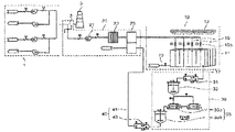
- FIG. 1 is a view showing the configuration of a microalgae culture apparatus using a conventional power plant exhaust gas.
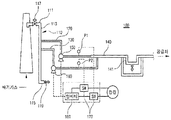
- Figure 2 is a system diagram showing the configuration of the extractor for industrial equipment capable of supplying a fixed amount of exhaust gas according to the present invention.
- Figure 2 is a system diagram showing the configuration of the extractor for industrial equipment capable of supplying a fixed amount of exhaust gas according to the present invention.
- the apparatus 100 for extracting exhaust gas according to the present invention capable of quantitatively supplying exhaust gas may include a first gas supply pipe 110, a first branch gas supply pipe 120, and a second branch gas supply pipe ( 130, the second gas supply pipe 140, the first blower 150, the second blower 160, the first pressure gauge P1, the second pressure gauge P2, and the switching element 170. Consists of including.
- the first gas supply pipe 110 is vertically bent from the first horizontal portion 111 and the first horizontal portion 111 formed at an upper end so as to horizontally penetrate the side surface of the stack 101 to the ground. Part 113 and the second horizontal portion 115 formed horizontally in the vertical portion 113 to extract a part of the exhaust gas of the stack 101.
- the first horizontal portion 111 of the first gas supply pipe 110 has a main valve 117 to supply and shut off the exhaust gas, and a predetermined distance from the ground to supply a uniform exhaust gas (eg, For example, if the stack of 80M (30M) is installed on the side of the stack.
- the first gas supply pipe 110 is provided with a solenoid valve 119 at the end of the second horizontal portion 115 to automatically discharge the condensed water to the outside.
- the first branch gas supply pipe 120 is installed at one lower side of the vertical part 113 of the first gas supply pipe 110. At this time, the diameter of the first branch gas supply pipe 120 is preferably formed smaller than the diameter of the first gas supply pipe (110).
- the second branch gas supply pipe 130 is installed in parallel with the first branch gas supply pipe 120 at one side of the lower end of the vertical portion of the first gas supply pipe 110.
- the diameter of the second branch gas supply pipe 130 is preferably formed smaller than the diameter of the first gas supply pipe (110).
- the second gas supply pipe 140 is installed to supply the exhaust gas supplied from the first branch gas supply pipe 120 and the second branch gas supply pipe 130 to a supply source such as a microalgae incubator and an absorption tower.
- the second gas supply pipe 140 includes a trap 141 to discharge the condensed water generated when the gas is supplied to the outside.
- the first blower 150 is installed on the first branch gas supply pipe 120 and operated according to the power control of the switching element 170 to be described below to remove the exhaust gas of the first gas supply pipe 110.
- the first quarter is supplied to the second gas supply pipe 140 through the gas supply pipe 120.
- the second blower 160 is installed on the second branch gas supply pipe 130 and operated under the control of the power supply of the switching element 170 to convert the exhaust gas of the first gas supply pipe 110 into the second branch gas supply pipe ( 130 is supplied to the second gas supply pipe 140 through.
- the first pressure gauge P1 is installed on the first branch gas supply pipe 120 to measure the pressure in the pipe and output a contact signal when the pressure exceeds the preset first reference pressure range.
- the first pressure gauge P1 outputs a contact signal for turning off the switching element 170 when exceeding the preset first reference pressure value range, and when it is below the preset first reference pressure value range, the switching element 170. Outputs a contact signal to turn on.
- the second pressure gauge (P2) is installed on the second branch gas supply pipe 130 to measure the pressure in the tube and outputs a contact signal when it exceeds or falls below the preset second reference pressure value range.
- the second pressure gauge P2 outputs a contact signal for turning off the switching element 170 when the second reference pressure value range is exceeded, and when the second pressure gauge P2 is lower than the second reference pressure value range, the switching element 170. Outputs a contact signal to turn on.
- the second pressure gauge (P2) is the second within the first reference pressure value range of the first pressure gauge (P1) to block the occurrence of the differential pressure or pulsation when supplying the exhaust gas to the second gas supply pipe 140
- the reference pressure value range is set to have a fast supply cycle. For example, when the first reference pressure value range is 0.15 to 0.3 kgf / cm 2, the second reference pressure value range is 0.18 to 0.2 kgf / cm 2. Is set to.
- the switching element 170 is installed in the first pressure gauge P1 and the second pressure gauge P2 as a relay, respectively, and supplies or cuts off power to the first blower 150 and the second blower 160.
- the apparatus 100 for extracting exhaust gas for industrial equipment may softly start the first blower 150 and the second blower 160 to prevent breakage due to sudden start. It is preferable to further include).
- the first pressure gauge P1 and the first pressure gauge P1 and the first pressure gauge P1 and the first pressure gauge P1 and the second branch gas supply pipe 130 are not supplied with the exhaust gas.
- a signal for turning on the switching element 170 is output from the pressure gauge P2.
- the switching element 170 is turned on to supply power to the first blower 150 and the second blower 160.
- the exhaust gas flows into the first branch gas supply pipe 120 and the second branch gas supply pipe 130, and is supplied to a supply source such as a microalgal incubator and an absorption tower through the second gas supply pipe 140.
- a supply source such as a microalgal incubator and an absorption tower through the second gas supply pipe 140.
- the first pressure gauge P1 or the second pressure gauge P2 exceeds the preset first and second reference pressure value ranges, the first pressure gauge P1 or the second pressure gauge P2
- the switching element 170 is turned off to cut off the power supply of the first blower 150 or the second blower 160.
- the first pressure gauge P1 or the second pressure gauge P2 measures the pressure in real time and repeats the above operation to supply the exhaust gas to the second gas supply pipe 140.
- the present invention can be used for equipment for culturing microalgae with exhaust gas, equipment for absorbing carbon dioxide contained in exhaust gas, and the like.
- first and second gas supply pipe 120, 130 first and second gas supply pipe
Landscapes
- Engineering & Computer Science (AREA)
- Chemical & Material Sciences (AREA)
- Health & Medical Sciences (AREA)
- Life Sciences & Earth Sciences (AREA)
- Wood Science & Technology (AREA)
- Organic Chemistry (AREA)
- Bioinformatics & Cheminformatics (AREA)
- Zoology (AREA)
- Biomedical Technology (AREA)
- General Engineering & Computer Science (AREA)
- Biotechnology (AREA)
- Genetics & Genomics (AREA)
- Sustainable Development (AREA)
- Microbiology (AREA)
- Biochemistry (AREA)
- General Health & Medical Sciences (AREA)
- Oil, Petroleum & Natural Gas (AREA)
- Environmental & Geological Engineering (AREA)
- Analytical Chemistry (AREA)
- General Chemical & Material Sciences (AREA)
- Chemical Kinetics & Catalysis (AREA)
- Molecular Biology (AREA)
- Mechanical Engineering (AREA)
- Combustion & Propulsion (AREA)
- Greenhouses (AREA)
- Treating Waste Gases (AREA)
Abstract
Description
본 발명은 배기가스 정량 공급이 가능한 산업설비용 추기장치에 관한 것으로서, 상세하게는 연돌에 가스 공급관을 설치하고, 가스 공급관에 두대의 블로워를 병렬로 설치하여 기설정된 압력값에 따라 각 블로워를 동작시켜 일정한 량의 배기가스를 공급하도록 하는 배기가스 정량 공급이 가능한 산업설비용 추기장치에 관한 것이다.The present invention relates to a bleeding device for industrial equipment capable of quantitatively supplying exhaust gas. Specifically, a gas supply pipe is installed in a stack, and two blowers are installed in parallel in a gas supply pipe to operate each blower according to a predetermined pressure value. The present invention relates to a bleeding device for industrial equipment capable of supplying a fixed amount of exhaust gas to supply a constant amount of exhaust gas.
화석 연료의 사용에 따른 온실가스의 배출로 인한 지구 온난화가 기후변화와 지구 환경 변화의 원인이 되고 있으며, 인류를 비롯한 지구 전 생명체의 생존을 위협하고 있다. 이에 이산화탄소를 저감시키기 위한 많은 연구와 개발이 이루어지고 있으며, 그 일환으로 이산화탄소를 회수하여 생물학적으로 전환시키는 분야에 대해서도 연구가 활발히 진행되고 있다.Global warming due to greenhouse gas emissions caused by the use of fossil fuels is causing climate change and global environmental change, threatening the survival of all human beings and the world. Accordingly, many researches and developments have been made to reduce carbon dioxide, and as a part thereof, research is being actively conducted in the field of recovering carbon dioxide and biologically converting it.
이산화탄소의 생물학적 전환 처리를 위한 광합성 생물로서, 미세조류에 대한 연구가 활발히 진행되고 있다. 식물성 플랑크톤인 미세조류는 여느 광합성 생물과 마찬가지로 태양을 에너지원으로 하며, 이산화탄소를 고정화하는 광합성 작용을 하며 성장하는 특성을 갖는다.As photosynthetic organisms for the biological conversion of carbon dioxide, research on microalgae is being actively conducted. Microalgae, phytoplankton, like other photosynthetic organisms, use the sun as an energy source, and have the property of growing photosynthesis to fix carbon dioxide.
미세조류가 이산화탄소를 고정화하는 수단으로 각광 받는 이유는 첫째, 식물이 이산화탄소를 흡수하는 경우와 마찬가지로 태양 에너지를 주 에너지원으로 활용할 수 있어 이산화탄소를 회수하기 위해 투입해야 하는 에너지가 아주 작다는 점이다. 따라서 이산화탄소 고정화 공정의 운전에 따른 이산화탄소 발생량이 작으므로 이산화탄소 수지 측면에서 제거 효율이 높다.The reason why microalgae is spotlighted as a means of immobilizing carbon dioxide is firstly, as in the case of plants absorbing carbon dioxide, solar energy can be used as a main energy source, so the energy required to recover carbon dioxide is very small. Therefore, since the amount of carbon dioxide generated by the operation of the carbon dioxide immobilization process is small, the removal efficiency is high in terms of carbon dioxide resin.
둘째, 식물에 비해 이산화탄소 고정화 속도가 매우 높아 소요 부지 면적이 적다는 점이다. 동경전력연구소의 연구 결과에 따르면 미세조류의 이산화탄소 고정화 속도는 같은 조류인 대형조류(Macroalgae)에 비해 8배, 우리나라의 가장 흔한 수종인 소나무에 비해서는 무려 16배 이상 높은 것으로 나타났다.Second, the carbon dioxide immobilization rate is much higher than that of plants, which requires less land area. According to the research results of the Tokyo Electric Power Research Institute, the rate of carbon dioxide immobilization of microalgae is 8 times higher than that of the same algae, Macroalgae, and 16 times higher than that of pine, the most common species in Korea.
이외에도 연소가스로부터 직접 이산화탄소를 고정화할 수 있어 이산화탄소에 대한 분리·농축 공정이 필요 없다는 장점이 있다. 게다가 이산화탄소 고정화 과정에 생산된 미세조류는 다양한 유용물질을 함유하고 있어 바이오 고가제품 생산에 활용이 가능하다.In addition, since carbon dioxide can be directly immobilized from the combustion gas, there is an advantage that no separation and concentration process for carbon dioxide is required. In addition, the microalgae produced during the carbon dioxide immobilization contain various useful substances, which can be used to produce bio-expensive products.
그러나 미세조류를 이용하여 이산화탄소를 고정화하는 공정을 실제 산업체에서 적용되는 생물 반응기로 수행할 경우, 전기 에너지의 소비가 높기 때문에, 에너지 절감 및 미세조류 성장에 필수적으로 필요한 빛 에너지의 공급이 수월하지 못한 문제점이 있다.However, when the process of immobilizing carbon dioxide using microalgae is carried out by a bioreactor applied in a real industry, it is difficult to supply light energy necessary for energy saving and microalgae growth because of high electric energy consumption. There is a problem.
이러한 문제점을 해결하기 위하여 국내 등록특허 10-1072844호(발전소 배기가스를 이용한 미세조류 배양장치)가 출원되어 공개되었다.In order to solve this problem, Korean Patent No. 10-1072844 (microalgae culture apparatus using a power plant exhaust gas) has been filed and published.
도 1에 도시된 바와 같이, 상기 발전소 배기가스를 이용한 미세조류 배양장치는 발전소(1)의 배기가스를 이용한 미세조류 배양장치는 배양부(10)와, 배기가스 공급부(20) 및 미세조류 추출부(30)를 포함한다.As shown in Figure 1, the microalgae culture apparatus using the exhaust gas of the power plant is a microalgae culture apparatus using the exhaust gas of the power plant 1 is the
배양부(10)는 미생물인 미세조류가 배양될 수 있도록 광합성 반응기(11)와, 이 광합성 반응기(11)에 빛을 조사하기 위한 빛 발생부재(13)로 구성된다. 이러한 배양부(10)는 그 온도가 적정하게 유지되도록 온실의 내부에 설치되며, 배기가스 공급부(20)에 의해 발전소(1)로부터 배기가스가 공급된다.The
구체적으로, 광합성 반응기(11)는 배기가스 공급부(20)에서 공급되는 배기가스가 보다 효과적으로 공급되도록 배기가스 공급라인(15)이 복수개 마련되며, 각각의 배기가스 공급라인(15)에 개폐밸브(15a)가 설치된다. 또한, 광합성 반응기(11)는 내부의 미세조류를 배출하기 위한 배수라인(17) 및 내부로 물을 보충하기 위한 물공급라인(19)이 형성된다.Specifically, the
이러한 광합성 반응기(11)는 배기가스 중의 이산화탄소(CO2) 및 배기가스의 열에 의해 미세조류의 배양환경이 안정되게 유지될 뿐만 아니라, 미세조류의 배양량이 증대되게 된다.The
빛 발생부재(13)는 미세조류의 배양이 더욱 촉진될 수 있도록 야간 또는 날씨기 흐릴 때 사용된다.The
배기가스 공급부(20)는 발전소(1)에서 발생되는 배기가스가 배양부(10)로 공급되도록 발전소(1)와 배양부(10)를 연결한다.The exhaust
이러한 배기가스 공급부(20)는 배기 팬(21)과, 필터부재(23) 및 열교환부(25)로 구성된다.The exhaust
배기 팬(21)은 발전소(1)의 배기라인(3)에 연결되어 배기라인(3)을 통해 연돌(5)로 배기되는 배기가스의 일부를 강제 흡입하여 광합성 반응기(11)로 공급하게 된다.The
필터부재(23)는 배기 팬(21)에 의해 배출되는 배기가스 중의 이물질을 제거한다.The
열교환부(25)는 필터부재(23)를 통과한 배기가스의 온도가 저하되도록 배기가스를 열교환시키게 된다.The
열교환부(25)에서 온도가 적정하게 저하된 배기가스는 배기가스 공급라인(15)을 통해 광합성 반응기(11)로 공급되어 이산화탄소가 제거된다.The exhaust gas whose temperature is appropriately lowered in the
미세조류 추출부(30)는 광합성 반응기(11)의 배수라인(17)에 설치되는 배수펌프(31)와, 배수펌프(31)에서 배수되는 물이 수용되는 수용탱크(33) 및 물과 미세조류를 분리하기 위한 분리부재(35)로 구성된다.The
배수펌프(31)는 광합성 반응기(11)에서 배양된 미세조류를 수용탱크(33)로 강제 배출시킨다. 배수펌프(31)에 의해 미세조류가 강제 배출될 때 광합성 반응기(11)의 물도 함께 배출된다.The
수용탱크(33)는 분리부재(35)와 연결되며, 내부에 수용된 물이 분리부재(35)로 공급된다.The
분리부재(35)는 수용탱크(33)의 물이 공급되며 회전력을 통해 물과 미세조류를 분리시키는 원심분리기(35a)와, 이 원심분리기(35a)에서 배수되는 물이 저장되는 저장탱크(35b)로 구성된다.
원심분리기(35a)는 미세조류의 분리 효율을 향상시킬 수 있도록 복수개 마련되며, 미세조류 분리시 발생되는 물이 저장탱크(35b)로 배수된다. 본 실시 예에서는 원심분리기(35a)가 두개 형성된 것이 도시되어 있지만, 원심분리기(35a)의 수는 사용자의 필요에 따라 한 개 또는 세 개 이상 형성할 수도 있다.The centrifugal separator 35a is provided in plural so as to improve the separation efficiency of the microalgae, and the water generated when the microalgae is separated is drained to the
저장탱크(35b)로 배수된 물은 배출수 공급부(40)에 의해 열교환부(25)로 공급되어 열교환부(25)의 열교환 매체로 사용된다.The water drained into the
이러한, 배출수 공급부(40)는 저장탱크(35b)의 물을 열교환부(25)로 공급할 수 있도록 저장탱크(35b)와 열교환부(25)를 연결하는 연결라인(41)과, 이 연결라인(41) 상에 설치되는 공급펌프(43)로 구성된다.The discharge
그러나, 이러한 종래의 발전소 배기가스를 이용한 미세조류 배양장치는 배기라인에 배기팬이 설치되는데, 가스 차압에 의해 원활한 배기가스의 공급이 이루어지지 못하고, 맥동 형태로 공급되어 배양부의 광합성 반응기가 압력에 의해 파손되거나 물이 넘치는 등의 문제점이 발생한다.However, in the conventional microalgal culture apparatus using the exhaust gas of the power plant, an exhaust fan is installed in the exhaust line, and the exhaust gas is not supplied smoothly by the gas differential pressure. This causes problems such as damage or overflow of water.
또한, 이러한 종래의 발전소 배기가스를 이용한 미세조류 배양장치는 배기가스에 포함된 수분으로 인해 배기라인에 물이 차고, 이로 인해 배기팬의 고장이 발생하고, 물이 광합성 배양기 내부로 유입되어 미세조류의 성장에 악영향을 미치는 문제점이 있다.In addition, the microalgae cultivation apparatus using the exhaust gas of the conventional power plant is filled with water in the exhaust line due to the moisture contained in the exhaust gas, which causes the failure of the exhaust fan, water is introduced into the photosynthetic incubator microalgae There is a problem that adversely affects the growth of the.
<선행기술문헌><Preceding technical literature>
특허문헌Patent Literature
국내 등록특허 10-1072844호Domestic Patent No. 10-1072844
본 발명은 상기와 같은 문제점을 해결하기 위한 것으로, 연돌에 가스 공급관을 설치하고, 가스 공급관에 두대의 블로워를 병렬로 설치하여 기설정된 압력값에 따라 각 블로워를 동작시켜 일정한 량의 배기가스를 공급하도록 하는 배기가스 정량 공급이 가능한 산업설비용 추기장치를 제공하는데 그 목적이 있다.The present invention is to solve the above problems, by installing a gas supply pipe in the stack, two blowers in parallel to the gas supply pipe to operate each blower in accordance with a predetermined pressure value to supply a certain amount of exhaust gas. An object of the present invention is to provide a bleeding device for industrial facilities capable of supplying a fixed amount of exhaust gas.
또한, 본 발명은 연돌과 수직으로 가스 공급관을 설치하고, 가스 공급관의 끝단에서 배기 가스 내 포함된 수분을 응축하고, 응축수를 외부로 배출하는 밸브를 설치하며, 가스 공급관의 응축수 수위보다 높은 위치에서 분기 가스관을 설치하여 블로워로 배기 가스를 공급하고, 블로워에서 배출되는 배기가스를 수요처까지 공급하도록 연장된 연결 배관에 트랩을 설치함으로써 물이 공급처로 유입되는 것을 차단하도록 하는 배기가스 정량 공급이 가능한 산업설비용 추기장치를 제공하는데 다른 목적이 있다.In addition, the present invention is to install a gas supply pipe perpendicular to the stack, to condense the moisture contained in the exhaust gas at the end of the gas supply pipe, to install a valve for discharging the condensate to the outside, at a position higher than the condensate level of the gas supply pipe An industry capable of supplying the exhaust gas quantitatively by installing a branch gas pipe to supply exhaust gas to the blower, and by installing a trap in the connecting pipe extended to supply the exhaust gas discharged from the blower to the demand destination. Another object is to provide a device extractor.
상기와 같은 목적을 달성하기 위한 본 발명의 특징은,Features of the present invention for achieving the above object,
연돌의 측면을 수평하게 관통하도록 상단에 형성되는 제 1수평부와, 상기 제 1수평부에서 수직으로 절곡되어 지상으로 향하는 수직부와, 상기 수직부에서 수평하게 형성되는 제 2수평부로 이루어져 상기 연돌의 배기가스의 일부를 추기하는 제 1가스 공급관과; 상기 제 1가스 공급관의 수직부 하단 일측에 설치되는 제 1분기 가스 공급관과; 상기 제 1가스 공급관의 수직부 하단 일측에서 상기 제 1분기 가스 공급관과 병렬로 설치되는 제 2분기 가스 공급관과; 상기 제 1분기 가스 공급관과 상기 제 2분기 가스 공급관으로부터 공급되는 배기가스를 공급처로 공급하도록 설치되는 제 2가스 공급관과; 상기 제 1분기 가스 공급관 상에 설치되어 외부의 전원 제어에 따라 동작되는 제 1블로워와; 상기 제 2분기 가스 공급관 상에 설치되어 외부의 전원 제어에 따라 동작되는 제 2블로워와; 상기 제 1분기 가스 공급관 상에 설치되어 관내 압력을 측정하여 기설정된 제 1기준 압력값 범위를 이탈하면 접점 신호를 출력하는 제 1압력계와;The stack includes a first horizontal portion formed at an upper end to horizontally penetrate the side surface of the stack, a vertical portion bent vertically at the first horizontal portion to the ground, and a second horizontal portion formed horizontally at the vertical portion. A first gas supply pipe for extracting a part of exhaust gas of the gas; A first branch gas supply pipe installed at one side of a lower end of the vertical part of the first gas supply pipe; A second branch gas supply pipe installed in parallel with the first branch gas supply pipe at a lower side of the vertical portion of the first gas supply pipe; A second gas supply pipe installed to supply exhaust gas supplied from the first branch gas supply pipe and the second branch gas supply pipe to a supply destination; A first blower installed on the first branch gas supply pipe and operated according to external power control; A second blower installed on the second branch gas supply pipe and operated according to external power control; A first pressure gauge installed on the first branch gas supply pipe and measuring a pressure in the pipe to output a contact signal when the pressure is out of a predetermined first reference pressure range;
상기 제 2분기 가스 공급관 상에 설치되어 관내 압력을 측정하여 기설정된 제 2기준 압력값 범위를 이탈하면 접점 신호를 출력하는 제 2압력계; 및 상기 제 1압력계와 제 2압력계로부터 출력되는 접점 신호에 따라 상기 제 1블로워와 제 2블로워에 전원을 공급하는 스위칭 소자로 이루어지는 것을 특징으로 한다.A second pressure gauge installed on the second branch gas supply pipe and measuring a pressure in the pipe to output a contact signal when the second reference pressure value is out of a range; And a switching element for supplying power to the first blower and the second blower according to a contact signal output from the first pressure gauge and the second pressure gauge.
여기에서, 상기 배기가스 정량 공급이 가능한 산업설비용 추기장치는 상기 제 1블로워와 제 2블로워를 소프트 기동시키는 인버터를 더 포함한다.Here, the apparatus for extracting industrial equipment capable of quantitatively supplying exhaust gas further includes an inverter for softly starting the first blower and the second blower.
여기에서 또한, 상기 제 1가스 공급관의 제 1수평부는 배기가스의 공급 및 차단하도록 메인 밸브를 구비한다.Here, the first horizontal portion of the first gas supply pipe is provided with a main valve to supply and shut off the exhaust gas.
여기에서 또, 상기 제 1가스 공급관의 제 1수평부는 균질의 배기가스를 공급하도록 지상으로부터 일정 거리 이격되어 상기 연돌의 측면에 설치된다.Here, the first horizontal portion of the first gas supply pipe is provided on the side of the stack spaced apart from the ground by a predetermined distance so as to supply a uniform exhaust gas.
여기에서 또, 상기 제 1가스 공급관은 상기 제 2수평부의 끝단에 응축수를 자동으로 외부로 배출하는 솔레노이드 밸브가 구비된다.Here, the first gas supply pipe is provided at the end of the second horizontal portion is provided with a solenoid valve for automatically discharging the condensed water to the outside.
여기에서 또, 상기 제 2가스 공급관은 응축수를 외부로 배출하도록 트랩이 구비된다.Here, the second gas supply pipe is provided with a trap to discharge the condensed water to the outside.
여기에서 또, 상기 제 1압력계의 접점 신호는 기설정된 제 1기준 압력값 범위를 초과할 때 상기 스위칭 소자를 오프시키는 접점 신호를 출력하고, 기설정된 제 1기준 압력값 범위 미만일 때 상기 스위칭 소자를 온(ON)시키는 접점 신호를 출력한다.Here, the contact signal of the first pressure gauge outputs a contact signal for turning off the switching element when the preset first reference pressure value range is exceeded, and when the contact signal is less than the preset first reference pressure value range, Outputs a contact signal that turns on.
여기에서 또, 상기 제 2압력계의 접점 신호는 기설정된 제 2기준 압력값 범위를 초과할 때 상기 스위칭 소자를 오프시키는 접점 신호를 출력하고, 기설정된 제 2기준 압력값 범위 미만일 때 상기 스위칭 소자를 온(ON)시키는 접점 신호를 출력한다.Here, the contact signal of the second pressure gauge outputs a contact signal for turning off the switching element when the second reference pressure value range is exceeded, and when the contact signal of the second pressure gauge is less than the second reference pressure value range, Outputs a contact signal that turns on.
여기에서 또, 상기 제 2압력계는 상기 제 1압력계의 제 1기준 압력값 범위 내에서 제 2기준 압력값 범위가 설정된다.Here, the second pressure gauge has a second reference pressure value range within the first reference pressure value range of the first pressure gauge.
상기와 같이 구성되는 본 발명인 배기가스 정량 공급이 가능한 산업설비용 추기장치에 따르면, 연돌에 가스 공급관을 설치하고, 가스 공급관에 두대의 블로워를 병렬로 설치하여 기설정된 압력값에 따라 각 블로워를 동작시켜 일정한 량의 배기가스를 공급할 수 있다.According to the extractor for industrial equipment capable of quantitatively supplying exhaust gas according to the present invention, the gas supply pipe is installed in the stack, and two blowers are installed in the gas supply pipe in parallel to operate each blower according to a predetermined pressure value. It is possible to supply a certain amount of exhaust gas.
또한, 본 발명에 따르면 연돌과 수직으로 가스 공급관을 설치하고, 가스 공급관의 끝단에서 배기 가스 내 포함된 수분을 응축하고, 응축수를 외부로 배출하는 밸브를 설치하며, 가스 공급관의 응축수 수위보다 높은 위치에서 분기 가스관을 설치하여 블로워로 배기 가스를 공급하고, 블로워에서 배출되는 배기가스를 수요처까지 공급하도록 연장된 연결 배관에 트랩을 설치함으로써 물이 공급처로 유입되는 것을 차단할 수 있다.Further, according to the present invention, the gas supply pipe is installed perpendicularly to the stack, the end of the gas supply pipe condenses moisture contained in the exhaust gas, and installs a valve for discharging the condensate to the outside, the position higher than the condensate water level of the gas supply pipe It is possible to block the inflow of water to the supply source by installing a branch gas pipe at the gas supply pipe to supply the exhaust gas to the blower, and by installing a trap at the connection pipe extending to supply the exhaust gas discharged from the blower to the demand destination.
도 1은 종래의 발전소 배기가스를 이용한 미세조류 배양장치의 구성을 나타낸 도면이다.1 is a view showing the configuration of a microalgae culture apparatus using a conventional power plant exhaust gas.
도 2는 본 발명에 따른 배기가스 정량 공급이 가능한 산업설비용 추기장치의 구성을 나타낸 계통도이다.Figure 2 is a system diagram showing the configuration of the extractor for industrial equipment capable of supplying a fixed amount of exhaust gas according to the present invention.
이하, 본 발명에 따른 배기가스 정량 공급이 가능한 산업설비용 추기장치의 구성을 첨부된 도면을 참조하여 상세하게 설명하면 다음과 같다.Hereinafter, with reference to the accompanying drawings, the configuration of the apparatus for extracting industrial equipment capable of quantitatively supplying exhaust gas according to the present invention will be described in detail.
하기에서 본 발명을 설명함에 있어, 관련된 공지 기능 또는 구성에 대한 구체적인 설명이 본 발명의 요지를 불필요하게 흐릴 수 있다고 판단되는 경우에는 그 상세한 설명은 생략할 것이다. 그리고 후술되는 용어들은 본 발명에서의 기능을 고려하여 정의된 용어들로서 이는 사용자, 운용자의 의도 또는 관례 등에 따라 달라질 수 있다. 그러므로 그 정의는 본 명세서 전반에 걸친 내용을 토대로 내려져야 할 것이다.In the following description of the present invention, if it is determined that a detailed description of a related known function or configuration may unnecessarily obscure the subject matter of the present invention, the detailed description thereof will be omitted. Terms to be described later are terms defined in consideration of functions in the present invention, and may be changed according to intentions or customs of users or operators. Therefore, the definition should be made based on the contents throughout the specification.
도 2는 본 발명에 따른 배기가스 정량 공급이 가능한 산업설비용 추기장치의 구성을 나타낸 계통도이다.Figure 2 is a system diagram showing the configuration of the extractor for industrial equipment capable of supplying a fixed amount of exhaust gas according to the present invention.
도 2를 참조하면, 본 발명에 따른 배기가스 정량 공급이 가능한 산업설비용 추기장치(100)는 제 1가스 공급관(110)과, 제 1분기 가스 공급관(120)과, 제 2분기 가스 공급관(130)과, 제 2가스 공급관(140)과, 제 1블로워(150)와, 제 2블로워(160)와, 제 1압력계(P1)와, 제 2압력계(P2)와, 스위칭 소자(170)를 포함하여 구성한다.Referring to FIG. 2, the
먼저, 제 1가스 공급관(110)은 연돌(101)의 측면을 수평하게 관통하도록 상단에 형성되는 제 1수평부(111)와, 제 1수평부(111)에서 수직으로 절곡되어 지상으로 향하는 수직부(113)와, 수직부(113)에서 수평하게 형성되는 제 2수평부(115)로 이루어져 연돌(101)의 배기가스의 일부를 추기한다. 여기에서, 제 1가스 공급관(110)의 제 1수평부(111)는 배기가스의 공급 및 차단하도록 메인 밸브(117)를 구비하고, 균질의 배기가스를 공급하도록 지상으로부터 일정 거리 이격(예를 들어, 80M의 연돌인 경우 30M)되어 연돌의 측면에 설치된다. 여기에서 또한, 제 1가스 공급관(110)은 제 2수평부(115)의 끝단에 응축수를 자동으로 외부로 배출하기 위한 솔레노이드 밸브(119)가 구비된다.First, the first
그리고, 제 1분기 가스 공급관(120)은 제 1가스 공급관(110)의 수직부(113) 하단 일측에 설치된다. 이때, 제 1분기 가스 공급관(120)의 지름은 제 1가스 공급관(110)의 지름보다 작게 형성되는 것이 바람직하다.In addition, the first branch
또한, 제 2분기 가스 공급관(130)은 제 1가스 공급관(110)의 수직부 하단 일측에서 제 1분기 가스 공급관(120)과 병렬로 설치된다. 이때, 제 2분기 가스 공급관(130)의 지름은 제 1가스 공급관(110)의 지름보다 작게 형성되는 것이 바람직하다.In addition, the second branch
또, 제 2가스 공급관(140)은 제 1분기 가스 공급관(120)과 제 2분기 가스 공급관(130)으로부터 각각 공급되는 배기가스를 미세조류 배양기, 흡수탑과 같은 공급처로 공급하도록 설치된다. 여기에서, 제 2가스 공급관(140)은 가스 공급시 발생하는 응축수를 외부로 배출할 수 있도록 트랩(141)을 구비한다.In addition, the second
계속해서, 제 1블로워(150)는 제 1분기 가스 공급관(120) 상에 설치되어 하기에서 설명할 스위칭 소자(170)의 전원 제어에 따라 동작되어 제 1가스 공급관(110)의 배기가스를 제 1분기 가스 공급관(120)을 통해 제 2가스 공급관(140)으로 공급한다.Subsequently, the
이어서, 제 2블로워(160)는 제 2분기 가스 공급관(130) 상에 설치되어 스위칭 소자(170)의 전원 제어에 따라 동작되어 제 1가스 공급관(110)의 배기가스를 제 2분기 가스 공급관(130)을 통해 제 2가스 공급관(140)으로 공급한다.Subsequently, the
그리고, 제 1압력계(P1)는 제 1분기 가스 공급관(120) 상에 설치되어 관내 압력을 측정하여 기설정된 제 1기준 압력값 범위를 초과하거나 미만인 경우 접점 신호를 출력한다. 여기에서, 제 1압력계(P1)는 기설정된 제 1기준 압력값 범위를 초과할 때 스위칭 소자(170)를 오프시키는 접점 신호를 출력하고, 기설정된 제 1기준 압력값 범위 미만일 때 스위칭 소자(170)를 온시키는 접점 신호를 출력한다.In addition, the first pressure gauge P1 is installed on the first branch
또한, 제 2압력계(P2)는 제 2분기 가스 공급관(130) 상에 설치되어 관내 압력을 측정하여 기설정된 제 2기준 압력값 범위를 초과하거나 미만인 경우 접점 신호를 출력한다. 여기에서, 제 2압력계(P2)는 기설정된 제 2기준 압력값 범위를 초과할 때 스위칭 소자(170)를 오프시키는 접점 신호를 출력하고, 기설정된 제 2기준 압력값 범위 미만일 때 스위칭 소자(170)를 온시키는 접점 신호를 출력한다. 여기에서 또한, 제 2압력계(P2)는 제 2가스 공급관(140)으로 배기가스를 공급할 시 차압이나 맥동이 발생하는 것을 차단하도록 제 1압력계(P1)의 제 1기준 압력값 범위 내에서 제 2기준 압력값 범위가 설정되어 빠른 공급 주기를 갖도록 하는 것이 바람직한데, 예를 들어, 제 1기준 압력값 범위가 0.15~0.3㎏f/㎠이면 제 2기준 압력값 범위는 0.18~0.2㎏f/㎠로 설정된다.In addition, the second pressure gauge (P2) is installed on the second branch
또, 스위칭 소자(170)는 릴레이로서 제 1압력계(P1)와 제 2압력계(P2)에 각각 설치되고, 따라 제 1블로워(150)와 제 2블로워(160)에 전원을 공급하거나 차단한다.In addition, the switching
한편, 본 발명에 따른 배기가스 정량 공급이 가능한 산업설비용 추기장치(100)는 제 1블로워(150)와 제 2블로워(160)를 소프트 기동시켜 급격 기동에 의해 파손되는 것을 방지하도록 인버터(180)를 더 포함하는 것이 바람직하다.Meanwhile, the
이하, 본 발명에 따른 배기가스 정량 공급이 가능한 산업설비용 추기장치의 동작을 첨부된 도면을 참조하여 상세하게 설명하면 다음과 같다.Hereinafter, with reference to the accompanying drawings, the operation of the bleeding apparatus for industrial equipment capable of quantitatively supplying exhaust gas according to the present invention will be described in detail.
먼저, 메인 밸브(117)가 개방되면 제 1가스 공급관(110)으로 연돌(101)의 배기가스가 유입된다.First, when the
이러한 상태에서, 제 1분기 가스 공급관(120)과 제 2분기 가스 공급관(130) 내에는 배기가스가 미공급된 상태로 제 1, 2기준 압력값 범위 미만이기 때문에 제 1압력계(P1)와 제 2압력계(P2)에서 스위칭 소자(170)를 온시키는 신호가 출력된다.In this state, in the first branch
그러면, 스위칭 소자(170)가 온되어 제 1블로워(150)와 제 2블로워(160)에 전원을 공급한다.Then, the switching
이로 인해 제 1분기 가스 공급관(120)과 제 2분기 가스 공급관(130)으로 배기가스가 유입되어 제 2가스 공급관(140)을 통해 미세조류 배양기, 흡수탑과 같은 공급처로 공급된다.As a result, the exhaust gas flows into the first branch
이러한 상태에서, 제 1압력계(P1) 또는 제 2압력계(P2)에서 측정된 압력이 기설정된 제 1, 2기준 압력값 범위를 초과하면, 제 1압력계(P1) 또는 제 2압력계(P2)는 스위칭 소자(170)를 오프시켜 제 1블로워(150) 또는 제 2블로워(160)의 전원 공급을 차단시킨다.In this state, when the pressure measured by the first pressure gauge P1 or the second pressure gauge P2 exceeds the preset first and second reference pressure value ranges, the first pressure gauge P1 or the second pressure gauge P2 The switching
계속해서, 제 1압력계(P1) 또는 제 2압력계(P2)는 압력을 실시간으로 측정하여 상기와 같은 동작을 반복하여 제 2가스 공급관(140)으로 배기가스를 공급한다.Subsequently, the first pressure gauge P1 or the second pressure gauge P2 measures the pressure in real time and repeats the above operation to supply the exhaust gas to the second
본 발명은 다양하게 변형될 수 있고 여러 가지 형태를 취할 수 있으며 상기 발명의 상세한 설명에서는 그에 따른 특별한 실시 예에 대해서만 기술하였다. 하지만 본 발명은 상세한 설명에서 언급되는 특별한 형태로 한정되는 것이 아닌 것으로 이해되어야 하며, 오히려 첨부된 청구범위에 의해 정의되는 본 발명의 정신과 범위 내에 있는 모든 변형물과 균등물 및 대체물을 포함하는 것으로 이해되어야 한다.As those skilled in the art would realize, the described embodiments may be modified in various ways, all without departing from the spirit or scope of the present invention. It is to be understood, however, that the present invention is not limited to the specific forms referred to in the description, but rather includes all modifications, equivalents, and substitutions within the spirit and scope of the invention as defined by the appended claims. Should be.
본 발명은 배기가스로 미세조류를 배양하는 설비와, 배기가스 내에 포함된 이산화탄소를 흡수하는 설비 등에 이용이 가능하다.The present invention can be used for equipment for culturing microalgae with exhaust gas, equipment for absorbing carbon dioxide contained in exhaust gas, and the like.
<부호의 설명><Description of the code>
110, 140 : 제 1, 2가스 공급관 120, 130 : 제 1, 2분기 가스 공급관110, 140: first and second
150, 160 : 제 1, 2블로워 170 : 스위칭 소자150, 160: 1st, 2nd blower 170: switching element
180 : 인버터 P1, P2 : 제 1, 2압력계180: inverter P1, P2: first, second pressure gauge
Claims (9)
Priority Applications (1)
| Application Number | Priority Date | Filing Date | Title |
|---|---|---|---|
| EP14876451.7A EP3093600B1 (en) | 2014-01-06 | 2014-07-03 | Industrial facility purge device capable of quantitatively supplying exhaust gas |
Applications Claiming Priority (2)
| Application Number | Priority Date | Filing Date | Title |
|---|---|---|---|
| KR10-2014-0001122 | 2014-01-06 | ||
| KR1020140001122A KR101408834B1 (en) | 2014-01-06 | 2014-01-06 | Extracting device supplying fixed quantity of exhaust gas for industrial facility |
Publications (1)
| Publication Number | Publication Date |
|---|---|
| WO2015102185A1 true WO2015102185A1 (en) | 2015-07-09 |
Family
ID=51133238
Family Applications (1)
| Application Number | Title | Priority Date | Filing Date |
|---|---|---|---|
| PCT/KR2014/005947 Ceased WO2015102185A1 (en) | 2014-01-06 | 2014-07-03 | Industrial facility purge device capable of quantitatively supplying exhaust gas |
Country Status (5)
| Country | Link |
|---|---|
| US (1) | US9475001B2 (en) |
| EP (1) | EP3093600B1 (en) |
| KR (1) | KR101408834B1 (en) |
| CN (1) | CN104762194A (en) |
| WO (1) | WO2015102185A1 (en) |
Families Citing this family (4)
| Publication number | Priority date | Publication date | Assignee | Title |
|---|---|---|---|---|
| KR101874995B1 (en) * | 2017-04-07 | 2018-07-06 | 한국지역난방공사 | Extracting and pretreatment system for capture of carbon dioxide in exhaust gas using district heating |
| KR102049383B1 (en) * | 2018-02-12 | 2019-11-28 | 한국지역난방공사 | Exhaust gas extraction equipment |
| AU2022266191B2 (en) * | 2021-04-27 | 2024-11-14 | Solar Foods Oyj | Method and system of adding feed medium into bioprocess |
| CN113513707B (en) * | 2021-05-09 | 2022-11-11 | 中国轻工业长沙工程有限公司 | Jet ignition type methane treatment device |
Citations (5)
| Publication number | Priority date | Publication date | Assignee | Title |
|---|---|---|---|---|
| JPH10229763A (en) * | 1997-02-20 | 1998-09-02 | Toshiba Eng & Constr Co Ltd | Greenhouse system |
| JP2000312532A (en) * | 1999-04-30 | 2000-11-14 | Miura Co Ltd | Supply of exhaust gas to facility for cultivating plant |
| JP2001292640A (en) * | 2000-04-11 | 2001-10-23 | Yamamoto Co Ltd | Method and apparatus for supplying carbon dioxide in greenhouses and houses |
| JP2006191876A (en) * | 2005-01-14 | 2006-07-27 | Mitsubishi Heavy Ind Ltd | Biomass utilization system |
| KR101072844B1 (en) | 2010-12-24 | 2011-10-14 | 한국남부발전 주식회사 | Microalgae Cultivation System Using Power Plant Exhaust Gas |
Family Cites Families (11)
| Publication number | Priority date | Publication date | Assignee | Title |
|---|---|---|---|---|
| FR2842192B1 (en) * | 2002-07-12 | 2004-10-01 | Snecma Propulsion Solide | PROCESS AND PLANT FOR OBTAINING CARBON PRODUCTS FROM CARBON PRECURSOR PRODUCTS |
| US8459984B2 (en) * | 2005-04-26 | 2013-06-11 | Heartland Technology Partners Llc | Waste heat recovery system |
| EP2134450A2 (en) * | 2007-03-08 | 2009-12-23 | Seambiotic Ltd. | Method for growing photosynthetic organisms |
| US7997081B2 (en) * | 2007-06-28 | 2011-08-16 | Officepower, Inc. | Gas delivery system |
| JP5039651B2 (en) * | 2008-07-08 | 2012-10-03 | 三菱重工業株式会社 | Carbon dioxide recovery system in exhaust gas |
| JP5495520B2 (en) * | 2008-07-23 | 2014-05-21 | 三菱重工業株式会社 | Carbon dioxide recovery device in exhaust gas |
| JP2011112030A (en) * | 2009-11-30 | 2011-06-09 | Ntn Corp | Gas supply device and exhaust gas power generation system |
| WO2012078821A2 (en) * | 2010-12-07 | 2012-06-14 | Jerry Lang | System and method for separating high molecular weight gases from a combustion source |
| NL2009899A (en) * | 2011-12-20 | 2013-06-24 | Asml Netherlands Bv | A pump system, a carbon dioxide supply system, an extraction system, a lithographic apparatus and a device manufacturing method. |
| US9221005B2 (en) * | 2013-06-17 | 2015-12-29 | Freudenberg Filtration Technologies, Llc | Self-regulating filtration system for weld smoke |
| EP2837778A1 (en) * | 2013-08-15 | 2015-02-18 | ALSTOM Technology Ltd | Operation of a gas turbine power plant with carbon dioxide separation |
-
2014
- 2014-01-06 KR KR1020140001122A patent/KR101408834B1/en active Active
- 2014-07-03 EP EP14876451.7A patent/EP3093600B1/en not_active Not-in-force
- 2014-07-03 WO PCT/KR2014/005947 patent/WO2015102185A1/en not_active Ceased
- 2014-07-16 US US14/333,392 patent/US9475001B2/en active Active
- 2014-08-01 CN CN201410376657.8A patent/CN104762194A/en active Pending
Patent Citations (5)
| Publication number | Priority date | Publication date | Assignee | Title |
|---|---|---|---|---|
| JPH10229763A (en) * | 1997-02-20 | 1998-09-02 | Toshiba Eng & Constr Co Ltd | Greenhouse system |
| JP2000312532A (en) * | 1999-04-30 | 2000-11-14 | Miura Co Ltd | Supply of exhaust gas to facility for cultivating plant |
| JP2001292640A (en) * | 2000-04-11 | 2001-10-23 | Yamamoto Co Ltd | Method and apparatus for supplying carbon dioxide in greenhouses and houses |
| JP2006191876A (en) * | 2005-01-14 | 2006-07-27 | Mitsubishi Heavy Ind Ltd | Biomass utilization system |
| KR101072844B1 (en) | 2010-12-24 | 2011-10-14 | 한국남부발전 주식회사 | Microalgae Cultivation System Using Power Plant Exhaust Gas |
Also Published As
| Publication number | Publication date |
|---|---|
| CN104762194A (en) | 2015-07-08 |
| EP3093600A1 (en) | 2016-11-16 |
| KR101408834B1 (en) | 2014-06-20 |
| EP3093600B1 (en) | 2018-11-28 |
| EP3093600A4 (en) | 2017-08-30 |
| US20150192252A1 (en) | 2015-07-09 |
| US9475001B2 (en) | 2016-10-25 |
Similar Documents
| Publication | Publication Date | Title |
|---|---|---|
| US8415142B2 (en) | Method and apparatus for CO2 sequestration | |
| JP2023027093A (en) | Photobioreactor device and method | |
| CA2777567C (en) | An apparatus and method for algae growth | |
| US20070289206A1 (en) | Method and apparatus for co2 sequestration | |
| WO2015102185A1 (en) | Industrial facility purge device capable of quantitatively supplying exhaust gas | |
| WO2015108279A1 (en) | Microalgae culturing system using wastewater and culturing method therefor | |
| US20130023044A1 (en) | System and Method for Fuel Generation from Algae | |
| BRPI0718284A2 (en) | SYSTEM AND PROCESS FOR PHOTOSYNTHETIC CELL GROWTH. | |
| ES2548249T3 (en) | Installation and process to recover methane from a liquid effluent | |
| WO2019172501A1 (en) | System for capturing and recycling carbon dioxide in exhaust gas | |
| EP2981604B1 (en) | Photobioreactor for co2 biosequestration with immobilised biomass of algae or cyanobacteria | |
| JP2018535690A5 (en) | ||
| US20130019753A1 (en) | System and Method for Separation of Captured Gases from Exhaust | |
| CN114191977A (en) | Industrial waste gas treatment device for realizing carbon neutralization by utilizing microalgae | |
| CN103946368A (en) | Process using exhaust gases for effecting growth of phototrophic biomass | |
| JPH08140662A (en) | High-concentration culture method and device for microalgae using deep water | |
| WO2022164137A1 (en) | Air purification device using microalgae | |
| KR101226627B1 (en) | Apparatus for culturing micro algae | |
| WO2017111221A1 (en) | Multifunctional port for culturing and collecting microalgae | |
| WO2025127340A1 (en) | Microalga culturing apparatus to be mounted on wall surface of structure, enabling easy detachment of microalga | |
| CN206666503U (en) | A kind of automation culture casing of high density oil-rich microalgae | |
| CN101466821A (en) | Method and device for CO2 sequestration | |
| WO2011011970A1 (en) | Apparatus for emission reduction testing of carbon dioxide and waste water and preparation of biodiesel, as well as method thereof | |
| CN203890351U (en) | Anaerobic bacterium culture device | |
| WO2010035939A1 (en) | Method for reducing carbon dioxide in the atmosphere using deep seawater, and method for preventing global warming using same |
Legal Events
| Date | Code | Title | Description |
|---|---|---|---|
| REEP | Request for entry into the european phase |
Ref document number: 2014876451 Country of ref document: EP |
|
| WWE | Wipo information: entry into national phase |
Ref document number: 2014876451 Country of ref document: EP |
|
| NENP | Non-entry into the national phase |
Ref country code: DE |
|
| 121 | Ep: the epo has been informed by wipo that ep was designated in this application |
Ref document number: 14876451 Country of ref document: EP Kind code of ref document: A1 |