WO2015102185A1 - Dispositif de purge d'installation industrielle permettant de fournir quantitativement du gaz d'échappement - Google Patents
Dispositif de purge d'installation industrielle permettant de fournir quantitativement du gaz d'échappement Download PDFInfo
- Publication number
- WO2015102185A1 WO2015102185A1 PCT/KR2014/005947 KR2014005947W WO2015102185A1 WO 2015102185 A1 WO2015102185 A1 WO 2015102185A1 KR 2014005947 W KR2014005947 W KR 2014005947W WO 2015102185 A1 WO2015102185 A1 WO 2015102185A1
- Authority
- WO
- WIPO (PCT)
- Prior art keywords
- supply pipe
- gas supply
- exhaust gas
- contact signal
- pressure gauge
- Prior art date
- Legal status (The legal status is an assumption and is not a legal conclusion. Google has not performed a legal analysis and makes no representation as to the accuracy of the status listed.)
- Ceased
Links
Images
Classifications
-
- B—PERFORMING OPERATIONS; TRANSPORTING
- B01—PHYSICAL OR CHEMICAL PROCESSES OR APPARATUS IN GENERAL
- B01D—SEPARATION
- B01D53/00—Separation of gases or vapours; Recovering vapours of volatile solvents from gases; Chemical or biological purification of waste gases, e.g. engine exhaust gases, smoke, fumes, flue gases, aerosols
- B01D53/34—Chemical or biological purification of waste gases
- B01D53/74—General processes for purification of waste gases; Apparatus or devices specially adapted therefor
- B01D53/84—Biological processes
-
- B—PERFORMING OPERATIONS; TRANSPORTING
- B01—PHYSICAL OR CHEMICAL PROCESSES OR APPARATUS IN GENERAL
- B01D—SEPARATION
- B01D53/00—Separation of gases or vapours; Recovering vapours of volatile solvents from gases; Chemical or biological purification of waste gases, e.g. engine exhaust gases, smoke, fumes, flue gases, aerosols
- B01D53/14—Separation of gases or vapours; Recovering vapours of volatile solvents from gases; Chemical or biological purification of waste gases, e.g. engine exhaust gases, smoke, fumes, flue gases, aerosols by absorption
- B01D53/1456—Removing acid components
- B01D53/1475—Removing carbon dioxide
-
- C—CHEMISTRY; METALLURGY
- C12—BIOCHEMISTRY; BEER; SPIRITS; WINE; VINEGAR; MICROBIOLOGY; ENZYMOLOGY; MUTATION OR GENETIC ENGINEERING
- C12M—APPARATUS FOR ENZYMOLOGY OR MICROBIOLOGY; APPARATUS FOR CULTURING MICROORGANISMS FOR PRODUCING BIOMASS, FOR GROWING CELLS OR FOR OBTAINING FERMENTATION OR METABOLIC PRODUCTS, i.e. BIOREACTORS OR FERMENTERS
- C12M21/00—Bioreactors or fermenters specially adapted for specific uses
- C12M21/02—Photobioreactors
-
- C—CHEMISTRY; METALLURGY
- C12—BIOCHEMISTRY; BEER; SPIRITS; WINE; VINEGAR; MICROBIOLOGY; ENZYMOLOGY; MUTATION OR GENETIC ENGINEERING
- C12M—APPARATUS FOR ENZYMOLOGY OR MICROBIOLOGY; APPARATUS FOR CULTURING MICROORGANISMS FOR PRODUCING BIOMASS, FOR GROWING CELLS OR FOR OBTAINING FERMENTATION OR METABOLIC PRODUCTS, i.e. BIOREACTORS OR FERMENTERS
- C12M29/00—Means for introduction, extraction or recirculation of materials, e.g. pumps
-
- C—CHEMISTRY; METALLURGY
- C12—BIOCHEMISTRY; BEER; SPIRITS; WINE; VINEGAR; MICROBIOLOGY; ENZYMOLOGY; MUTATION OR GENETIC ENGINEERING
- C12M—APPARATUS FOR ENZYMOLOGY OR MICROBIOLOGY; APPARATUS FOR CULTURING MICROORGANISMS FOR PRODUCING BIOMASS, FOR GROWING CELLS OR FOR OBTAINING FERMENTATION OR METABOLIC PRODUCTS, i.e. BIOREACTORS OR FERMENTERS
- C12M43/00—Combinations of bioreactors or fermenters with other apparatus
- C12M43/04—Bioreactors or fermenters combined with combustion devices or plants, e.g. for carbon dioxide removal
-
- F—MECHANICAL ENGINEERING; LIGHTING; HEATING; WEAPONS; BLASTING
- F17—STORING OR DISTRIBUTING GASES OR LIQUIDS
- F17D—PIPE-LINE SYSTEMS; PIPE-LINES
- F17D3/00—Arrangements for supervising or controlling working operations
- F17D3/01—Arrangements for supervising or controlling working operations for controlling, signalling, or supervising the conveyance of a product
-
- F—MECHANICAL ENGINEERING; LIGHTING; HEATING; WEAPONS; BLASTING
- F17—STORING OR DISTRIBUTING GASES OR LIQUIDS
- F17D—PIPE-LINE SYSTEMS; PIPE-LINES
- F17D3/00—Arrangements for supervising or controlling working operations
- F17D3/14—Arrangements for supervising or controlling working operations for eliminating water
-
- F—MECHANICAL ENGINEERING; LIGHTING; HEATING; WEAPONS; BLASTING
- F17—STORING OR DISTRIBUTING GASES OR LIQUIDS
- F17D—PIPE-LINE SYSTEMS; PIPE-LINES
- F17D5/00—Protection or supervision of installations
- F17D5/005—Protection or supervision of installations of gas pipelines, e.g. alarm
-
- B—PERFORMING OPERATIONS; TRANSPORTING
- B01—PHYSICAL OR CHEMICAL PROCESSES OR APPARATUS IN GENERAL
- B01D—SEPARATION
- B01D2251/00—Reactants
- B01D2251/95—Specific microorganisms
-
- B—PERFORMING OPERATIONS; TRANSPORTING
- B01—PHYSICAL OR CHEMICAL PROCESSES OR APPARATUS IN GENERAL
- B01D—SEPARATION
- B01D2257/00—Components to be removed
- B01D2257/50—Carbon oxides
- B01D2257/504—Carbon dioxide
-
- B—PERFORMING OPERATIONS; TRANSPORTING
- B01—PHYSICAL OR CHEMICAL PROCESSES OR APPARATUS IN GENERAL
- B01D—SEPARATION
- B01D2257/00—Components to be removed
- B01D2257/80—Water
-
- B—PERFORMING OPERATIONS; TRANSPORTING
- B01—PHYSICAL OR CHEMICAL PROCESSES OR APPARATUS IN GENERAL
- B01D—SEPARATION
- B01D2258/00—Sources of waste gases
- B01D2258/02—Other waste gases
- B01D2258/0283—Flue gases
-
- Y—GENERAL TAGGING OF NEW TECHNOLOGICAL DEVELOPMENTS; GENERAL TAGGING OF CROSS-SECTIONAL TECHNOLOGIES SPANNING OVER SEVERAL SECTIONS OF THE IPC; TECHNICAL SUBJECTS COVERED BY FORMER USPC CROSS-REFERENCE ART COLLECTIONS [XRACs] AND DIGESTS
- Y02—TECHNOLOGIES OR APPLICATIONS FOR MITIGATION OR ADAPTATION AGAINST CLIMATE CHANGE
- Y02A—TECHNOLOGIES FOR ADAPTATION TO CLIMATE CHANGE
- Y02A50/00—TECHNOLOGIES FOR ADAPTATION TO CLIMATE CHANGE in human health protection, e.g. against extreme weather
- Y02A50/20—Air quality improvement or preservation, e.g. vehicle emission control or emission reduction by using catalytic converters
-
- Y—GENERAL TAGGING OF NEW TECHNOLOGICAL DEVELOPMENTS; GENERAL TAGGING OF CROSS-SECTIONAL TECHNOLOGIES SPANNING OVER SEVERAL SECTIONS OF THE IPC; TECHNICAL SUBJECTS COVERED BY FORMER USPC CROSS-REFERENCE ART COLLECTIONS [XRACs] AND DIGESTS
- Y02—TECHNOLOGIES OR APPLICATIONS FOR MITIGATION OR ADAPTATION AGAINST CLIMATE CHANGE
- Y02C—CAPTURE, STORAGE, SEQUESTRATION OR DISPOSAL OF GREENHOUSE GASES [GHG]
- Y02C20/00—Capture or disposal of greenhouse gases
- Y02C20/40—Capture or disposal of greenhouse gases of CO2
-
- Y—GENERAL TAGGING OF NEW TECHNOLOGICAL DEVELOPMENTS; GENERAL TAGGING OF CROSS-SECTIONAL TECHNOLOGIES SPANNING OVER SEVERAL SECTIONS OF THE IPC; TECHNICAL SUBJECTS COVERED BY FORMER USPC CROSS-REFERENCE ART COLLECTIONS [XRACs] AND DIGESTS
- Y10—TECHNICAL SUBJECTS COVERED BY FORMER USPC
- Y10T—TECHNICAL SUBJECTS COVERED BY FORMER US CLASSIFICATION
- Y10T137/00—Fluid handling
- Y10T137/0318—Processes
- Y10T137/0396—Involving pressure control
-
- Y—GENERAL TAGGING OF NEW TECHNOLOGICAL DEVELOPMENTS; GENERAL TAGGING OF CROSS-SECTIONAL TECHNOLOGIES SPANNING OVER SEVERAL SECTIONS OF THE IPC; TECHNICAL SUBJECTS COVERED BY FORMER USPC CROSS-REFERENCE ART COLLECTIONS [XRACs] AND DIGESTS
- Y10—TECHNICAL SUBJECTS COVERED BY FORMER USPC
- Y10T—TECHNICAL SUBJECTS COVERED BY FORMER US CLASSIFICATION
- Y10T137/00—Fluid handling
- Y10T137/2931—Diverse fluid containing pressure systems
- Y10T137/3003—Fluid separating traps or vents
-
- Y—GENERAL TAGGING OF NEW TECHNOLOGICAL DEVELOPMENTS; GENERAL TAGGING OF CROSS-SECTIONAL TECHNOLOGIES SPANNING OVER SEVERAL SECTIONS OF THE IPC; TECHNICAL SUBJECTS COVERED BY FORMER USPC CROSS-REFERENCE ART COLLECTIONS [XRACs] AND DIGESTS
- Y10—TECHNICAL SUBJECTS COVERED BY FORMER USPC
- Y10T—TECHNICAL SUBJECTS COVERED BY FORMER US CLASSIFICATION
- Y10T137/00—Fluid handling
- Y10T137/8593—Systems
- Y10T137/85978—With pump
- Y10T137/85986—Pumped fluid control
-
- Y—GENERAL TAGGING OF NEW TECHNOLOGICAL DEVELOPMENTS; GENERAL TAGGING OF CROSS-SECTIONAL TECHNOLOGIES SPANNING OVER SEVERAL SECTIONS OF THE IPC; TECHNICAL SUBJECTS COVERED BY FORMER USPC CROSS-REFERENCE ART COLLECTIONS [XRACs] AND DIGESTS
- Y10—TECHNICAL SUBJECTS COVERED BY FORMER USPC
- Y10T—TECHNICAL SUBJECTS COVERED BY FORMER US CLASSIFICATION
- Y10T137/00—Fluid handling
- Y10T137/8593—Systems
- Y10T137/85978—With pump
- Y10T137/86131—Plural
-
- Y—GENERAL TAGGING OF NEW TECHNOLOGICAL DEVELOPMENTS; GENERAL TAGGING OF CROSS-SECTIONAL TECHNOLOGIES SPANNING OVER SEVERAL SECTIONS OF THE IPC; TECHNICAL SUBJECTS COVERED BY FORMER USPC CROSS-REFERENCE ART COLLECTIONS [XRACs] AND DIGESTS
- Y10—TECHNICAL SUBJECTS COVERED BY FORMER USPC
- Y10T—TECHNICAL SUBJECTS COVERED BY FORMER US CLASSIFICATION
- Y10T137/00—Fluid handling
- Y10T137/8593—Systems
- Y10T137/85978—With pump
- Y10T137/86131—Plural
- Y10T137/86163—Parallel
Definitions
- the present invention relates to a bleeding device for industrial equipment capable of quantitatively supplying exhaust gas.
- a gas supply pipe is installed in a stack, and two blowers are installed in parallel in a gas supply pipe to operate each blower according to a predetermined pressure value.
- the present invention relates to a bleeding device for industrial equipment capable of supplying a fixed amount of exhaust gas to supply a constant amount of exhaust gas.
- microalgae is spotlighted as a means of immobilizing carbon dioxide is firstly, as in the case of plants absorbing carbon dioxide, solar energy can be used as a main energy source, so the energy required to recover carbon dioxide is very small. Therefore, since the amount of carbon dioxide generated by the operation of the carbon dioxide immobilization process is small, the removal efficiency is high in terms of carbon dioxide resin.
- the carbon dioxide immobilization rate is much higher than that of plants, which requires less land area.
- the rate of carbon dioxide immobilization of microalgae is 8 times higher than that of the same algae, Macroalgae, and 16 times higher than that of pine, the most common species in Korea.
- carbon dioxide can be directly immobilized from the combustion gas, there is an advantage that no separation and concentration process for carbon dioxide is required.
- the microalgae produced during the carbon dioxide immobilization contain various useful substances, which can be used to produce bio-expensive products.
- Korean Patent No. 10-1072844 microalgae culture apparatus using a power plant exhaust gas
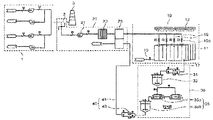
- the microalgae culture apparatus using the exhaust gas of the power plant is a microalgae culture apparatus using the exhaust gas of the power plant 1 is the culture unit 10, the exhaust gas supply unit 20 and the microalgae extraction The unit 30 is included.
- the culture unit 10 is composed of a photosynthesis reactor 11 and a light generating member 13 for irradiating light to the photosynthesis reactor 11 so that microalgae that are microorganisms can be cultured.
- the culture unit 10 is installed inside the greenhouse so that the temperature thereof is appropriately maintained, and the exhaust gas is supplied from the power plant 1 by the exhaust gas supply unit 20.
- the photosynthetic reactor 11 is provided with a plurality of exhaust gas supply line 15 to more effectively supply the exhaust gas supplied from the exhaust gas supply unit 20, each of the exhaust gas supply line 15 on and off valve ( 15a) is installed.
- the photosynthetic reactor 11 is formed with a drain line 17 for discharging the microalgae therein and a water supply line 19 for replenishing water therein.
- the photosynthetic reactor 11 not only stably maintains the microalgal culture environment by the carbon dioxide (CO 2 ) and the heat of the exhaust gas in the exhaust gas, but also increases the culture amount of the microalgae.
- the light generating member 13 is used when it is cloudy at night or in weather so that the culture of the microalgae can be further promoted.
- the exhaust gas supply unit 20 connects the power plant 1 and the culture unit 10 so that the exhaust gas generated from the power plant 1 is supplied to the culture unit 10.
- the exhaust gas supply unit 20 includes an exhaust fan 21, a filter member 23, and a heat exchanger 25.
- the exhaust fan 21 is connected to the exhaust line 3 of the power plant 1 to forcibly suck a part of the exhaust gas exhausted to the stack 5 through the exhaust line 3 to supply it to the photosynthesis reactor 11. .
- the filter member 23 removes foreign substances in the exhaust gas discharged by the exhaust fan 21.
- the heat exchanger 25 heat-exchanges the exhaust gas so that the temperature of the exhaust gas passing through the filter member 23 is lowered.
- the exhaust gas whose temperature is appropriately lowered in the heat exchange unit 25 is supplied to the photosynthesis reactor 11 through the exhaust gas supply line 15 to remove carbon dioxide.
- the microalgae extraction unit 30 is a drain pump 31 installed in the drain line 17 of the photosynthetic reactor 11, a receiving tank 33 for receiving the water drained from the drain pump 31 and water and fine It consists of a separating member 35 for separating the algae.
- the drain pump 31 forcibly discharges the microalgae cultured in the photosynthesis reactor 11 to the receiving tank 33.
- the microalgae is forcibly discharged by the drainage pump 31, the water of the photosynthetic reactor 11 is also discharged.
- the receiving tank 33 is connected to the separating member 35, and the water received therein is supplied to the separating member 35.
- Separation member 35 is a centrifuge (35a) is supplied with the water of the receiving tank 33 and the rotational force to separate the water and microalgae, and the storage tank (35b) for storing the water drained from the centrifuge (35a) It is composed of
- the centrifugal separator 35a is provided in plural so as to improve the separation efficiency of the microalgae, and the water generated when the microalgae is separated is drained to the storage tank 35b. Although two centrifuges 35a are shown in this embodiment, the number of centrifuges 35a may be one or three or more, depending on the needs of the user.
- the water drained into the storage tank 35b is supplied to the heat exchange part 25 by the discharge water supply part 40 and used as a heat exchange medium of the heat exchange part 25.
- the discharge water supply unit 40 has a connection line 41 for connecting the storage tank 35b and the heat exchanger 25 to supply the water from the storage tank 35b to the heat exchanger 25, and the connection line ( 41, the feed pump 43 is provided.
- the microalgae cultivation apparatus using the exhaust gas of the conventional power plant is filled with water in the exhaust line due to the moisture contained in the exhaust gas, which causes the failure of the exhaust fan, water is introduced into the photosynthetic incubator microalgae There is a problem that adversely affects the growth of the.
- the present invention is to solve the above problems, by installing a gas supply pipe in the stack, two blowers in parallel to the gas supply pipe to operate each blower in accordance with a predetermined pressure value to supply a certain amount of exhaust gas.
- An object of the present invention is to provide a bleeding device for industrial facilities capable of supplying a fixed amount of exhaust gas.
- the present invention is to install a gas supply pipe perpendicular to the stack, to condense the moisture contained in the exhaust gas at the end of the gas supply pipe, to install a valve for discharging the condensate to the outside, at a position higher than the condensate level of the gas supply pipe
- the stack includes a first horizontal portion formed at an upper end to horizontally penetrate the side surface of the stack, a vertical portion bent vertically at the first horizontal portion to the ground, and a second horizontal portion formed horizontally at the vertical portion.
- a first gas supply pipe for extracting a part of exhaust gas of the gas A first branch gas supply pipe installed at one side of a lower end of the vertical part of the first gas supply pipe; A second branch gas supply pipe installed in parallel with the first branch gas supply pipe at a lower side of the vertical portion of the first gas supply pipe; A second gas supply pipe installed to supply exhaust gas supplied from the first branch gas supply pipe and the second branch gas supply pipe to a supply destination;
- a first blower installed on the first branch gas supply pipe and operated according to external power control;
- a first pressure gauge installed on the first branch gas supply pipe and measuring a pressure in the pipe to output a contact signal when the pressure is out of a predetermined first reference pressure range;
- a second pressure gauge installed on the second branch gas supply pipe and measuring a pressure in the pipe to output a contact signal when the second reference pressure value is out of a range; And a switching element for supplying power to the first blower and the second blower according to a contact signal output from the first pressure gauge and the second pressure gauge.
- the apparatus for extracting industrial equipment capable of quantitatively supplying exhaust gas further includes an inverter for softly starting the first blower and the second blower.
- the first horizontal portion of the first gas supply pipe is provided with a main valve to supply and shut off the exhaust gas.
- the first horizontal portion of the first gas supply pipe is provided on the side of the stack spaced apart from the ground by a predetermined distance so as to supply a uniform exhaust gas.
- the first gas supply pipe is provided at the end of the second horizontal portion is provided with a solenoid valve for automatically discharging the condensed water to the outside.
- the second gas supply pipe is provided with a trap to discharge the condensed water to the outside.
- the contact signal of the first pressure gauge outputs a contact signal for turning off the switching element when the preset first reference pressure value range is exceeded, and when the contact signal is less than the preset first reference pressure value range, Outputs a contact signal that turns on.
- the contact signal of the second pressure gauge outputs a contact signal for turning off the switching element when the second reference pressure value range is exceeded, and when the contact signal of the second pressure gauge is less than the second reference pressure value range, Outputs a contact signal that turns on.
- the second pressure gauge has a second reference pressure value range within the first reference pressure value range of the first pressure gauge.
- the gas supply pipe is installed in the stack, and two blowers are installed in the gas supply pipe in parallel to operate each blower according to a predetermined pressure value. It is possible to supply a certain amount of exhaust gas.
- the gas supply pipe is installed perpendicularly to the stack, the end of the gas supply pipe condenses moisture contained in the exhaust gas, and installs a valve for discharging the condensate to the outside, the position higher than the condensate water level of the gas supply pipe It is possible to block the inflow of water to the supply source by installing a branch gas pipe at the gas supply pipe to supply the exhaust gas to the blower, and by installing a trap at the connection pipe extending to supply the exhaust gas discharged from the blower to the demand destination.
- FIG. 1 is a view showing the configuration of a microalgae culture apparatus using a conventional power plant exhaust gas.
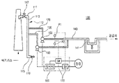
- Figure 2 is a system diagram showing the configuration of the extractor for industrial equipment capable of supplying a fixed amount of exhaust gas according to the present invention.
- Figure 2 is a system diagram showing the configuration of the extractor for industrial equipment capable of supplying a fixed amount of exhaust gas according to the present invention.
- the apparatus 100 for extracting exhaust gas according to the present invention capable of quantitatively supplying exhaust gas may include a first gas supply pipe 110, a first branch gas supply pipe 120, and a second branch gas supply pipe ( 130, the second gas supply pipe 140, the first blower 150, the second blower 160, the first pressure gauge P1, the second pressure gauge P2, and the switching element 170. Consists of including.
- the first gas supply pipe 110 is vertically bent from the first horizontal portion 111 and the first horizontal portion 111 formed at an upper end so as to horizontally penetrate the side surface of the stack 101 to the ground. Part 113 and the second horizontal portion 115 formed horizontally in the vertical portion 113 to extract a part of the exhaust gas of the stack 101.
- the first horizontal portion 111 of the first gas supply pipe 110 has a main valve 117 to supply and shut off the exhaust gas, and a predetermined distance from the ground to supply a uniform exhaust gas (eg, For example, if the stack of 80M (30M) is installed on the side of the stack.
- the first gas supply pipe 110 is provided with a solenoid valve 119 at the end of the second horizontal portion 115 to automatically discharge the condensed water to the outside.
- the first branch gas supply pipe 120 is installed at one lower side of the vertical part 113 of the first gas supply pipe 110. At this time, the diameter of the first branch gas supply pipe 120 is preferably formed smaller than the diameter of the first gas supply pipe (110).
- the second branch gas supply pipe 130 is installed in parallel with the first branch gas supply pipe 120 at one side of the lower end of the vertical portion of the first gas supply pipe 110.
- the diameter of the second branch gas supply pipe 130 is preferably formed smaller than the diameter of the first gas supply pipe (110).
- the second gas supply pipe 140 is installed to supply the exhaust gas supplied from the first branch gas supply pipe 120 and the second branch gas supply pipe 130 to a supply source such as a microalgae incubator and an absorption tower.
- the second gas supply pipe 140 includes a trap 141 to discharge the condensed water generated when the gas is supplied to the outside.
- the first blower 150 is installed on the first branch gas supply pipe 120 and operated according to the power control of the switching element 170 to be described below to remove the exhaust gas of the first gas supply pipe 110.
- the first quarter is supplied to the second gas supply pipe 140 through the gas supply pipe 120.
- the second blower 160 is installed on the second branch gas supply pipe 130 and operated under the control of the power supply of the switching element 170 to convert the exhaust gas of the first gas supply pipe 110 into the second branch gas supply pipe ( 130 is supplied to the second gas supply pipe 140 through.
- the first pressure gauge P1 is installed on the first branch gas supply pipe 120 to measure the pressure in the pipe and output a contact signal when the pressure exceeds the preset first reference pressure range.
- the first pressure gauge P1 outputs a contact signal for turning off the switching element 170 when exceeding the preset first reference pressure value range, and when it is below the preset first reference pressure value range, the switching element 170. Outputs a contact signal to turn on.
- the second pressure gauge (P2) is installed on the second branch gas supply pipe 130 to measure the pressure in the tube and outputs a contact signal when it exceeds or falls below the preset second reference pressure value range.
- the second pressure gauge P2 outputs a contact signal for turning off the switching element 170 when the second reference pressure value range is exceeded, and when the second pressure gauge P2 is lower than the second reference pressure value range, the switching element 170. Outputs a contact signal to turn on.
- the second pressure gauge (P2) is the second within the first reference pressure value range of the first pressure gauge (P1) to block the occurrence of the differential pressure or pulsation when supplying the exhaust gas to the second gas supply pipe 140
- the reference pressure value range is set to have a fast supply cycle. For example, when the first reference pressure value range is 0.15 to 0.3 kgf / cm 2, the second reference pressure value range is 0.18 to 0.2 kgf / cm 2. Is set to.
- the switching element 170 is installed in the first pressure gauge P1 and the second pressure gauge P2 as a relay, respectively, and supplies or cuts off power to the first blower 150 and the second blower 160.
- the apparatus 100 for extracting exhaust gas for industrial equipment may softly start the first blower 150 and the second blower 160 to prevent breakage due to sudden start. It is preferable to further include).
- the first pressure gauge P1 and the first pressure gauge P1 and the first pressure gauge P1 and the first pressure gauge P1 and the second branch gas supply pipe 130 are not supplied with the exhaust gas.
- a signal for turning on the switching element 170 is output from the pressure gauge P2.
- the switching element 170 is turned on to supply power to the first blower 150 and the second blower 160.
- the exhaust gas flows into the first branch gas supply pipe 120 and the second branch gas supply pipe 130, and is supplied to a supply source such as a microalgal incubator and an absorption tower through the second gas supply pipe 140.
- a supply source such as a microalgal incubator and an absorption tower through the second gas supply pipe 140.
- the first pressure gauge P1 or the second pressure gauge P2 exceeds the preset first and second reference pressure value ranges, the first pressure gauge P1 or the second pressure gauge P2
- the switching element 170 is turned off to cut off the power supply of the first blower 150 or the second blower 160.
- the first pressure gauge P1 or the second pressure gauge P2 measures the pressure in real time and repeats the above operation to supply the exhaust gas to the second gas supply pipe 140.
- the present invention can be used for equipment for culturing microalgae with exhaust gas, equipment for absorbing carbon dioxide contained in exhaust gas, and the like.
- first and second gas supply pipe 120, 130 first and second gas supply pipe
Landscapes
- Engineering & Computer Science (AREA)
- Chemical & Material Sciences (AREA)
- Health & Medical Sciences (AREA)
- Life Sciences & Earth Sciences (AREA)
- Wood Science & Technology (AREA)
- Organic Chemistry (AREA)
- Bioinformatics & Cheminformatics (AREA)
- Zoology (AREA)
- Biomedical Technology (AREA)
- General Engineering & Computer Science (AREA)
- Biotechnology (AREA)
- Genetics & Genomics (AREA)
- Sustainable Development (AREA)
- Microbiology (AREA)
- Biochemistry (AREA)
- General Health & Medical Sciences (AREA)
- Oil, Petroleum & Natural Gas (AREA)
- Environmental & Geological Engineering (AREA)
- Analytical Chemistry (AREA)
- General Chemical & Material Sciences (AREA)
- Chemical Kinetics & Catalysis (AREA)
- Molecular Biology (AREA)
- Mechanical Engineering (AREA)
- Combustion & Propulsion (AREA)
- Greenhouses (AREA)
- Treating Waste Gases (AREA)
Abstract
La présente invention porte sur un dispositif de purge d'installation industrielle qui permet de fournir quantitativement du gaz d'échappement et, plus précisément, sur un dispositif de purge d'installation industrielle qui permet de fournir quantitativement du gaz d'échappement, un tuyau de fourniture de gaz étant disposé dans une cheminée, deux soufflantes étant disposées parallèlement au tuyau de fourniture de gaz et chaque soufflante étant amenée à fonctionner en fonction d'une valeur de pression prédéfinie afin de fournir une quantité fixe de gaz d'échappement.
Priority Applications (1)
| Application Number | Priority Date | Filing Date | Title |
|---|---|---|---|
| EP14876451.7A EP3093600B1 (fr) | 2014-01-06 | 2014-07-03 | Dispositif de purge d'installation industrielle permettant de fournir quantitativement du gaz d'échappement |
Applications Claiming Priority (2)
| Application Number | Priority Date | Filing Date | Title |
|---|---|---|---|
| KR10-2014-0001122 | 2014-01-06 | ||
| KR1020140001122A KR101408834B1 (ko) | 2014-01-06 | 2014-01-06 | 배기가스 정량 공급이 가능한 산업설비용 추기장치 |
Publications (1)
| Publication Number | Publication Date |
|---|---|
| WO2015102185A1 true WO2015102185A1 (fr) | 2015-07-09 |
Family
ID=51133238
Family Applications (1)
| Application Number | Title | Priority Date | Filing Date |
|---|---|---|---|
| PCT/KR2014/005947 Ceased WO2015102185A1 (fr) | 2014-01-06 | 2014-07-03 | Dispositif de purge d'installation industrielle permettant de fournir quantitativement du gaz d'échappement |
Country Status (5)
| Country | Link |
|---|---|
| US (1) | US9475001B2 (fr) |
| EP (1) | EP3093600B1 (fr) |
| KR (1) | KR101408834B1 (fr) |
| CN (1) | CN104762194A (fr) |
| WO (1) | WO2015102185A1 (fr) |
Families Citing this family (4)
| Publication number | Priority date | Publication date | Assignee | Title |
|---|---|---|---|---|
| KR101874995B1 (ko) * | 2017-04-07 | 2018-07-06 | 한국지역난방공사 | 지역난방열을 이용한 배기가스 내 이산화탄소 포집용 추기 및 전처리 시스템 |
| KR102049383B1 (ko) * | 2018-02-12 | 2019-11-28 | 한국지역난방공사 | 배기가스 추기 장치 |
| AU2022266191B2 (en) * | 2021-04-27 | 2024-11-14 | Solar Foods Oyj | Method and system of adding feed medium into bioprocess |
| CN113513707B (zh) * | 2021-05-09 | 2022-11-11 | 中国轻工业长沙工程有限公司 | 喷射点燃式沼气处理装置 |
Citations (5)
| Publication number | Priority date | Publication date | Assignee | Title |
|---|---|---|---|---|
| JPH10229763A (ja) * | 1997-02-20 | 1998-09-02 | Toshiba Eng & Constr Co Ltd | 温室装置 |
| JP2000312532A (ja) * | 1999-04-30 | 2000-11-14 | Miura Co Ltd | 植物栽培用施設への排気ガスの供給方法 |
| JP2001292640A (ja) * | 2000-04-11 | 2001-10-23 | Yamamoto Co Ltd | 温室・ハウスにおける炭酸ガスの供給方法と供給装置 |
| JP2006191876A (ja) * | 2005-01-14 | 2006-07-27 | Mitsubishi Heavy Ind Ltd | バイオマス利活用システム |
| KR101072844B1 (ko) | 2010-12-24 | 2011-10-14 | 한국남부발전 주식회사 | 발전소 배기가스를 이용한 미세조류 배양장치 |
Family Cites Families (11)
| Publication number | Priority date | Publication date | Assignee | Title |
|---|---|---|---|---|
| FR2842192B1 (fr) * | 2002-07-12 | 2004-10-01 | Snecma Propulsion Solide | Procede et installation pour l'obtention de produits en carbone a partir de produits en precurseur de carbone |
| US8459984B2 (en) * | 2005-04-26 | 2013-06-11 | Heartland Technology Partners Llc | Waste heat recovery system |
| EP2134450A2 (fr) * | 2007-03-08 | 2009-12-23 | Seambiotic Ltd. | Procédé pour la croissance d'organismes photosynthétiques |
| US7997081B2 (en) * | 2007-06-28 | 2011-08-16 | Officepower, Inc. | Gas delivery system |
| JP5039651B2 (ja) * | 2008-07-08 | 2012-10-03 | 三菱重工業株式会社 | 排ガス中の二酸化炭素回収システム |
| JP5495520B2 (ja) * | 2008-07-23 | 2014-05-21 | 三菱重工業株式会社 | 排ガス中の二酸化炭素回収装置 |
| JP2011112030A (ja) * | 2009-11-30 | 2011-06-09 | Ntn Corp | ガス供給装置および排ガス発電システム |
| WO2012078821A2 (fr) * | 2010-12-07 | 2012-06-14 | Jerry Lang | Système et procédé de séparation de gaz de masse moléculaire élevée provenant d'une source de combustion |
| NL2009899A (en) * | 2011-12-20 | 2013-06-24 | Asml Netherlands Bv | A pump system, a carbon dioxide supply system, an extraction system, a lithographic apparatus and a device manufacturing method. |
| US9221005B2 (en) * | 2013-06-17 | 2015-12-29 | Freudenberg Filtration Technologies, Llc | Self-regulating filtration system for weld smoke |
| EP2837778A1 (fr) * | 2013-08-15 | 2015-02-18 | ALSTOM Technology Ltd | Fonctionnement d'une centrale électrique à turbine à gaz avec séparation de dioxyde de carbone |
-
2014
- 2014-01-06 KR KR1020140001122A patent/KR101408834B1/ko active Active
- 2014-07-03 EP EP14876451.7A patent/EP3093600B1/fr not_active Not-in-force
- 2014-07-03 WO PCT/KR2014/005947 patent/WO2015102185A1/fr not_active Ceased
- 2014-07-16 US US14/333,392 patent/US9475001B2/en active Active
- 2014-08-01 CN CN201410376657.8A patent/CN104762194A/zh active Pending
Patent Citations (5)
| Publication number | Priority date | Publication date | Assignee | Title |
|---|---|---|---|---|
| JPH10229763A (ja) * | 1997-02-20 | 1998-09-02 | Toshiba Eng & Constr Co Ltd | 温室装置 |
| JP2000312532A (ja) * | 1999-04-30 | 2000-11-14 | Miura Co Ltd | 植物栽培用施設への排気ガスの供給方法 |
| JP2001292640A (ja) * | 2000-04-11 | 2001-10-23 | Yamamoto Co Ltd | 温室・ハウスにおける炭酸ガスの供給方法と供給装置 |
| JP2006191876A (ja) * | 2005-01-14 | 2006-07-27 | Mitsubishi Heavy Ind Ltd | バイオマス利活用システム |
| KR101072844B1 (ko) | 2010-12-24 | 2011-10-14 | 한국남부발전 주식회사 | 발전소 배기가스를 이용한 미세조류 배양장치 |
Also Published As
| Publication number | Publication date |
|---|---|
| CN104762194A (zh) | 2015-07-08 |
| EP3093600A1 (fr) | 2016-11-16 |
| KR101408834B1 (ko) | 2014-06-20 |
| EP3093600B1 (fr) | 2018-11-28 |
| EP3093600A4 (fr) | 2017-08-30 |
| US20150192252A1 (en) | 2015-07-09 |
| US9475001B2 (en) | 2016-10-25 |
Similar Documents
| Publication | Publication Date | Title |
|---|---|---|
| US8415142B2 (en) | Method and apparatus for CO2 sequestration | |
| JP2023027093A (ja) | 光バイオリアクターデバイスおよび方法 | |
| CA2777567C (fr) | Un appareil et une methode de croissance des algues | |
| US20070289206A1 (en) | Method and apparatus for co2 sequestration | |
| WO2015102185A1 (fr) | Dispositif de purge d'installation industrielle permettant de fournir quantitativement du gaz d'échappement | |
| WO2015108279A1 (fr) | Système de culture d'algues microscopiques utilisant les eaux usées et leur procédé de culture | |
| US20130023044A1 (en) | System and Method for Fuel Generation from Algae | |
| BRPI0718284A2 (pt) | Sistema e processo para o crescimento de células fotossintéticas. | |
| ES2548249T3 (es) | Instalación y proceso para recuperar metano a partir de un efluente líquido | |
| WO2019172501A1 (fr) | Système de capture et de recyclage de dioxyde de carbone dans un gaz d'échappement | |
| EP2981604B1 (fr) | Photobioréacteur servant à la bioséquestration du co2 comportant une biomasse d'algues ou de cyanobactéries | |
| JP2018535690A5 (fr) | ||
| US20130019753A1 (en) | System and Method for Separation of Captured Gases from Exhaust | |
| CN114191977A (zh) | 一种利用微藻实现碳中和的工业废气处理装置 | |
| CN103946368A (zh) | 利用废气使光养生物质生长的方法 | |
| JPH08140662A (ja) | 深層水利用による微細藻類の高濃度培養法および装置 | |
| WO2022164137A1 (fr) | Dispositif de purification d'air à l'aide de microalgues | |
| KR101226627B1 (ko) | 미세조류 배양장치 | |
| WO2017111221A1 (fr) | Orifice multifonction pour la culture et la collecte de microalgues | |
| WO2025127340A1 (fr) | Appareil de culture de microalgue destiné à être monté sur une surface de paroi d'une structure, permettant un détachement facile de microalgue | |
| CN206666503U (zh) | 一种高密度富油微藻的自动化培养箱体 | |
| CN101466821A (zh) | 用于co2截存的方法和装置 | |
| WO2011011970A1 (fr) | Appareil pour lessai de réduction démission de dioxyde de carbone et deau usée et de préparation de biodiesel, ainsi quun procédé correspondant | |
| CN203890351U (zh) | 一种厌氧菌培养装置 | |
| WO2010035939A1 (fr) | Procédé de réduction du co2 atmosphérique au moyen d'eau de mer profonde et méthode de prévention du réchauffement climatique |
Legal Events
| Date | Code | Title | Description |
|---|---|---|---|
| REEP | Request for entry into the european phase |
Ref document number: 2014876451 Country of ref document: EP |
|
| WWE | Wipo information: entry into national phase |
Ref document number: 2014876451 Country of ref document: EP |
|
| NENP | Non-entry into the national phase |
Ref country code: DE |
|
| 121 | Ep: the epo has been informed by wipo that ep was designated in this application |
Ref document number: 14876451 Country of ref document: EP Kind code of ref document: A1 |