WO2015104931A1 - 画像形成装置 - Google Patents
画像形成装置 Download PDFInfo
- Publication number
- WO2015104931A1 WO2015104931A1 PCT/JP2014/082303 JP2014082303W WO2015104931A1 WO 2015104931 A1 WO2015104931 A1 WO 2015104931A1 JP 2014082303 W JP2014082303 W JP 2014082303W WO 2015104931 A1 WO2015104931 A1 WO 2015104931A1
- Authority
- WO
- WIPO (PCT)
- Prior art keywords
- toner
- image forming
- forming apparatus
- unit
- transport path
- Prior art date
- Legal status (The legal status is an assumption and is not a legal conclusion. Google has not performed a legal analysis and makes no representation as to the accuracy of the status listed.)
- Ceased
Links
Images


Classifications
-
- G—PHYSICS
- G03—PHOTOGRAPHY; CINEMATOGRAPHY; ANALOGOUS TECHNIQUES USING WAVES OTHER THAN OPTICAL WAVES; ELECTROGRAPHY; HOLOGRAPHY
- G03G—ELECTROGRAPHY; ELECTROPHOTOGRAPHY; MAGNETOGRAPHY
- G03G15/00—Apparatus for electrographic processes using a charge pattern
- G03G15/06—Apparatus for electrographic processes using a charge pattern for developing
- G03G15/08—Apparatus for electrographic processes using a charge pattern for developing using a solid developer, e.g. powder developer
- G03G15/0822—Arrangements for preparing, mixing, supplying or dispensing developer
- G03G15/0848—Arrangements for testing or measuring developer properties or quality, e.g. charge, size, flowability
- G03G15/0849—Detection or control means for the developer concentration
-
- G—PHYSICS
- G03—PHOTOGRAPHY; CINEMATOGRAPHY; ANALOGOUS TECHNIQUES USING WAVES OTHER THAN OPTICAL WAVES; ELECTROGRAPHY; HOLOGRAPHY
- G03G—ELECTROGRAPHY; ELECTROPHOTOGRAPHY; MAGNETOGRAPHY
- G03G15/00—Apparatus for electrographic processes using a charge pattern
- G03G15/06—Apparatus for electrographic processes using a charge pattern for developing
- G03G15/08—Apparatus for electrographic processes using a charge pattern for developing using a solid developer, e.g. powder developer
- G03G15/0822—Arrangements for preparing, mixing, supplying or dispensing developer
- G03G15/0863—Arrangements for preparing, mixing, supplying or dispensing developer provided with identifying means or means for storing process- or use parameters, e.g. an electronic memory
-
- G—PHYSICS
- G03—PHOTOGRAPHY; CINEMATOGRAPHY; ANALOGOUS TECHNIQUES USING WAVES OTHER THAN OPTICAL WAVES; ELECTROGRAPHY; HOLOGRAPHY
- G03G—ELECTROGRAPHY; ELECTROPHOTOGRAPHY; MAGNETOGRAPHY
- G03G15/00—Apparatus for electrographic processes using a charge pattern
- G03G15/06—Apparatus for electrographic processes using a charge pattern for developing
- G03G15/08—Apparatus for electrographic processes using a charge pattern for developing using a solid developer, e.g. powder developer
- G03G15/0822—Arrangements for preparing, mixing, supplying or dispensing developer
- G03G15/0877—Arrangements for metering and dispensing developer from a developer cartridge into the development unit
- G03G15/0879—Arrangements for metering and dispensing developer from a developer cartridge into the development unit for dispensing developer from a developer cartridge not directly attached to the development unit
-
- G—PHYSICS
- G03—PHOTOGRAPHY; CINEMATOGRAPHY; ANALOGOUS TECHNIQUES USING WAVES OTHER THAN OPTICAL WAVES; ELECTROGRAPHY; HOLOGRAPHY
- G03G—ELECTROGRAPHY; ELECTROPHOTOGRAPHY; MAGNETOGRAPHY
- G03G15/00—Apparatus for electrographic processes using a charge pattern
- G03G15/55—Self-diagnostics; Malfunction or lifetime display
-
- G—PHYSICS
- G03—PHOTOGRAPHY; CINEMATOGRAPHY; ANALOGOUS TECHNIQUES USING WAVES OTHER THAN OPTICAL WAVES; ELECTROGRAPHY; HOLOGRAPHY
- G03G—ELECTROGRAPHY; ELECTROPHOTOGRAPHY; MAGNETOGRAPHY
- G03G2215/00—Apparatus for electrophotographic processes
- G03G2215/01—Apparatus for electrophotographic processes for producing multicoloured copies
- G03G2215/0103—Plural electrographic recording members
- G03G2215/0119—Linear arrangement adjacent plural transfer points
- G03G2215/0122—Linear arrangement adjacent plural transfer points primary transfer to an intermediate transfer belt
- G03G2215/0125—Linear arrangement adjacent plural transfer points primary transfer to an intermediate transfer belt the linear arrangement being horizontal or slanted
- G03G2215/0129—Linear arrangement adjacent plural transfer points primary transfer to an intermediate transfer belt the linear arrangement being horizontal or slanted horizontal medium transport path at the secondary transfer
Definitions
- the present invention relates to an image forming apparatus such as a copying machine, a printer, and a facsimile.
- Some recent image forming apparatuses can use special color toners in addition to process color toners of CMYK (cyan (C), magenta (M), yellow (Y), black (K)).
- the special color toner includes, for example, clear toner (transparent toner, colorless toner, achromatic toner, no pigment toner) and R (red) G (green) B (blue) toner.
- An image forming apparatus that can use clear toner performs gloss adjustment by printing clear toner on the entire surface or a part of the color printed matter. Therefore, it is possible to generate printed matter with high added value.
- RGB toner An image forming apparatus that can use RGB toner can reproduce a color that is difficult to reproduce by superimposing CMYK process color toners with high quality.
- CMYK process color toners In addition to these special color toners, there are various special color toners.
- An image forming apparatus capable of using such a special color toner is known to have a special color toner image forming station in addition to the CMYK process color toner image forming stations. By providing a plurality of image forming stations corresponding to various kinds of special color toners, it is possible to generate printed matter with high added value.
- an image forming apparatus that can use special color toner is known that can be replaced with an image forming station of different types of toner (for example, see Patent Document 1).
- the image forming apparatus described in Patent Document 1 is configured to be able to exchange the process color toner image forming station and the special color toner image forming station, thereby enabling the order of superimposing the process color toner and the special color toner to be controlled. High value-added printed matter can be generated.
- the process color toner imaging station is replaced with a special color toner imaging station
- the special color toner imaging station is replaced with a process color toner imaging station
- the special color toner imaging station is replaced with a special color toner.
- the image forming apparatus described in Patent Document 1 may cause color mixing (contamination, contamination, mixing, etc.) that is not intended by the user when replacing different types of toner. Therefore, there are problems such as generation of abnormal images and damage to the image forming unit. Further, the image forming apparatus described in Patent Document 1 is exchanged for each image forming station. However, since the image forming station is large in size, there is a problem in handling. Further, such an image forming station requires a highly rigid frame and is heavy, so that there is a problem in exchange workability.
- Patent Document 2 since the image forming apparatus described in Patent Document 2 performs the operation of replacing different types of toner after the toner in the developer is discharged and made to be in a state where it has run out, there is a desire to reduce the waiting time during the replacement operation. was there.
- An object of the present invention is to provide an image forming apparatus that can be easily replaced with a different type of toner, suppress waste of toner, and prevent toner color mixture.
- an image forming apparatus In order to solve the above-described problem, an image forming apparatus according to claim 1 of the present invention is provided.
- the replenishment toner transport path includes at least one of the plurality of connection means corresponding to one of the plurality of toner containers as a component.
- Each of the components can be individually replaced, and the toner type detecting means for detecting the toner type used by each of the components, and all the components constituting the same replenishment toner transport path
- the notification means for notifying whether or not the toner types used in the respective components are the same, and the notification based on the detection information by the toner type detection means when the components of the replenishment toner transport path are replaced.
- Control means for controlling the means is provided.
- the present invention it is possible to provide an image forming apparatus that can be easily replaced with a different type of toner, suppress waste of toner, and prevent toner color mixture.
- FIG. 1 is a configuration diagram schematically illustrating an image forming apparatus according to an embodiment of the present invention.
- FIG. 2 is a configuration diagram schematically illustrating a control unit of the image forming apparatus illustrated in FIG. 1.
- FIG. 2 is a configuration diagram schematically showing a replenishment toner conveyance path of the image forming apparatus shown in FIG. 1.
- FIG. 2 is an explanatory diagram illustrating a replenishment toner conveyance path of the image forming apparatus illustrated in FIG. 1.
- FIG. 2 is an explanatory diagram for explaining an attachment / detachment state detection unit and a toner type detection unit of the image forming apparatus illustrated in FIG. 1.
- FIG. 1 is a configuration diagram schematically illustrating an image forming apparatus according to an embodiment of the present invention.
- FIG. 2 is a configuration diagram schematically illustrating a control unit of the image forming apparatus illustrated in FIG. 1.
- FIG. 2 is a configuration diagram schematically showing a replenishment toner conveyance path of the image forming apparatus shown in FIG. 1.
- FIG. 2 is an explanatory diagram for explaining an activation flow of an RFID tag attached to each component constituting a first toner conveyance path of the image forming apparatus shown in FIG. 1.
- FIG. 2 is an explanatory diagram for explaining replacement of a first toner conveyance path of the image forming apparatus illustrated in FIG. 1.
- 3 is a flowchart for explaining replacement of components of a first toner conveyance path of the image forming apparatus shown in FIG. 6 is a flowchart for describing recognition processing of attachment / detachment of components of the first toner conveyance path of the image forming apparatus illustrated in FIG. 1.
- 6 is a flowchart for describing toner type recognition processing of components of a first toner conveyance path of the image forming apparatus illustrated in FIG. 1.
- FIG. 2 is an explanatory diagram for explaining replacement of components of a first toner conveyance path of the image forming apparatus illustrated in FIG. 1.
- 3 is a flowchart for explaining replacement of components of a first toner conveyance path of the image forming apparatus shown in FIG.
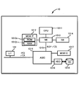
- the image forming apparatus 1 forms an image by fixing a toner image on a sheet as an example of a recording medium.
- the image forming apparatus 1 includes a control unit 10, an image reading unit 11, an image forming unit 12, a paper feeding unit 13, a transfer unit 14, a fixing unit 15, a paper discharge unit 16, and a display / operation unit 17. Etc.
- the image reading unit 11 generates image information by optically reading an image written on a sheet. Specifically, the image information is read by applying light to the paper and receiving the reflected light with a reading sensor such as a CCD (Charge Coupled Devices) or CIS (Contact Image Sensor).
- the image information is information representing an image to be formed on a recording medium such as paper, and uses electrical color separation image signals indicating red (R), green (G), and blue (B) colors. It is shown.
- the image reading unit 11 includes a contact glass 111, a reading sensor 112, and the like as shown in FIG.
- the contact glass 111 is for placing a sheet on which an image is written.
- the reading sensor 112 reads image information of an image described on a sheet placed on the contact glass 111.
- the image forming unit 12 applies process color toner and special color toner to the surface of the intermediate transfer belt 143 of the transfer unit 14 based on image information read by the image reading unit 11 or image information received by the network I / F 102.
- An image (toner image) is formed by adhering.
- the image forming unit 12 includes image forming units 120C, 120M, 120Y, 120K, and 120T that form toner images of each color of cyan (C), magenta (M), yellow (Y), black (K), and clear (T). It has.
- the C color toner, M color toner, Y color toner, and K color toner are referred to as process color toners, and the T color toner is referred to as a special color toner.
- Each process color toner is a chargeable resin particle containing a coloring material such as a pigment or a dye.
- the image forming unit 120 includes a toner bottle 121 as a toner container, a photosensitive drum 122 as an image carrier, a charging unit 123, an exposure unit 124, a developing unit 125 as a developing unit, a charge eliminating unit 126, a cleaning unit 127, and the like. I have.
- the toner bottle 121 contains toner of each color.
- the toner bottle 121 can be accommodated in a toner container accommodating portion formed in the image forming apparatus main body.
- the toner stored in the toner bottle 121 is supplied to the developing unit 125 by a predetermined amount.
- the toner bottles 121C, 121M, 121Y, and 121K for process color toners are connected via supply tubes 181C, 181M, 181Y, and 181K directly above or above the developing units 125C, 125M, 125Y, and 125K, respectively. Then, when the toner drops from the process color toner bottles 121C, 121M, 121Y, and 121K, the toner is supplied to the developing units 125C, 125M, 125Y, and 125K via the supply tubes 181C, 181M, 181Y, and 181K. It is like that. Therefore, the image forming apparatus can be reduced in size.
- the toner bottle 121T of the special color toner is connected to the developing unit 125T via a supply tube 181T as a connecting means, a diaphragm pump 183T as a conveying means, and a sub hopper 182T.
- the toner in the toner bottle 121T of special color toner is supplied to the developing unit 125T by the pressure of the diaphragm pump 183T. Therefore, the toner bottle 121T of the special color toner can be installed at any position without being affected by the position of the developing unit 125T.
- the scanner is installed at the top of the image forming apparatus 1 in consideration of its usability.
- process color toner bottles 121C, 121M, 121Y, and 121K are sequentially installed in series in order to reduce the size of the image forming apparatus 1.
- a toner bottle 121T of special color toner is installed below the toner bottle 121K.
- the toner bottle 121T of the special color toner When the toner bottle 121T of the special color toner is installed, for example, below the toner bottle 121K, it can be installed in a place that is not easily affected by heat from the fixing unit 15. Therefore, it is possible to prevent deterioration of the special color toner contained in the special color toner bottle 121T. Further, the toner bottle 121T can be installed at a position different from the arrangement of the toner bottles 121C, 121M, 121Y, and 121K for the process color toner. Therefore, when the user changes the toner type of the special color toner, it is possible to prevent the toner bottle 121T from being attached to an incorrect position.
- the surface of the photosensitive drum 122 is uniformly charged by the charging unit 123, and an electrostatic latent image is formed on the surface by the exposure unit 124 based on the image information received from the control unit 10.
- a toner image is formed when the developing unit 125 attaches toner to the surface of the photosensitive drum 122 on which the electrostatic latent image is formed.
- the photosensitive drum 122 is provided so as to be in contact with the intermediate transfer belt 143, and is provided to rotate in the same direction as the moving direction of the intermediate transfer belt 143 at a contact point with the intermediate transfer belt 143.
- the charging unit 123 uniformly charges the surface of the photosensitive drum 122.
- the exposure unit 124 irradiates the surface of the photosensitive drum 122 charged by the charging unit 123 with light based on the dot area ratio of each color determined by the control unit 10 to form an electrostatic latent image.
- the developing unit 125 develops the electrostatic latent image formed on the surface of the photosensitive drum 122 by the exposure unit 124 by attaching the toner of each color stored in the developer storage unit (toner bottle) 121 to the electrostatic latent image. A toner image is formed.
- the neutralization unit 126 neutralizes the surface of the photosensitive drum 122 after the image is transferred to the intermediate transfer belt 143.
- the cleaning unit 127 removes the transfer residual toner remaining on the surface of the photosensitive drum 122 that has been neutralized by the neutralization unit 126.
- the special color toner image forming unit 120T is installed at the most upstream position in the transport direction of the intermediate transfer belt 143 as compared to the process color toner image forming units 120C, 120M, 120Y, and 120K. Therefore, since the special color toner is transferred to the surface layer from the process color toner on the printed material, it is possible to generate a printed material with high added value utilizing the characteristics of the special color toner.
- the paper feed unit 13 supplies paper to the transfer unit 14.
- the paper feed unit 13 includes a paper storage unit 131, a paper feed roller 132, a paper feed belt 133, and a registration roller (positioning roller) 134.
- the paper storage unit 131 stores paper.
- the paper feed roller 132 is provided so as to rotate in order to move the paper stored in the paper storage unit 131 toward the paper supply belt 133.
- the paper feed roller 132 provided in this way takes out the uppermost one of the stored paper one by one and sends it out to the paper feed belt 133.
- the paper feed belt 133 conveys the paper fed by the paper feed roller 132 to the transfer unit 14.
- the registration roller 134 feeds the sheet conveyed by the sheet feeding belt 133 at a timing when a portion where a toner image is formed on the intermediate transfer belt 143 described later reaches the transfer unit 14.
- the transfer unit 14 transfers (primary transfer) the image formed on the photosensitive drum 122 by the image forming unit 12 to the intermediate transfer belt 143, and transfers the image transferred to the intermediate transfer belt 143 to the sheet (secondary transfer). To do.
- the transfer unit 14 includes a driving roller 141, a driven roller 142, an intermediate transfer belt 143, primary transfer rollers 144C, 144M, 144Y, 144K, and 144T, a secondary transfer roller 145, and a secondary opposing roller 146.
- the driving roller 141 hangs the intermediate transfer belt 143 together with the driven roller 142. As the driving roller 141 is driven and rotated, the intermediate transfer belt 143 that is being moved moves.
- the driven roller 142 hangs the intermediate transfer belt 143 together with the driving roller 141.
- the driven roller 142 rotates as the driving roller 141 rotates and the intermediate transfer belt 143 moves.
- the intermediate transfer belt 143 is stretched over the driving roller 141 and the driven roller 142 and moves while contacting the photosensitive drum 122 as the driving roller 141 rotates. As the intermediate transfer belt 143 moves while being in contact with the photosensitive drum 122, the image formed on the photosensitive drum 122 is transferred to the surface of the intermediate transfer belt 143.
- the primary transfer rollers 144C, 144M, 144Y, 144K, and 144T are provided to face the photosensitive drums 122C, 122M, 122Y, 122K, and 122T, respectively, with the intermediate transfer belt 143 interposed therebetween, and move the intermediate transfer belt 143. Rotate to.
- the secondary transfer roller 145 rotates with the intermediate transfer belt 143 and the paper sandwiched between the secondary opposing roller 146.
- the fixing unit 15 fixes the toner transferred to the sheet by the transfer unit 14. Fixing refers to fusing the resin component of the toner to the paper by simultaneously applying heat and pressure to the toner. By fixing the toner transferred to the paper by the transfer unit 14, the state of the toner on the paper becomes stable.
- the fixing unit 15 includes a conveyance belt 151, a fixing belt 152, a fixing roller 153, a fixing belt conveyance roller 154, a fixing counter roller 155, and a heat generation unit 156.
- the conveying belt 151 conveys the sheet onto which the toner has been transferred by the transfer unit 14 toward the fixing roller 153 and the fixing counter roller 155.
- the fixing belt 152 is stretched between the fixing roller 153 and the fixing belt conveying roller 154, and moves as the rollers rotate.
- the fixing roller 153 sandwiches the sheet transported by the transport belt 151 between the fixing facing roller 155 disposed opposite to the sheet, and heats and pressurizes the sheet.
- the fixing belt conveyance roller 154 is used to hang the fixing belt 152 together with the fixing roller 153, and the fixing belt 152 is also rotated by the rotation of the fixing belt conveyance roller 154.
- the fixing counter roller 155 is installed facing the fixing roller 153, and sandwiches the conveyed paper between the fixing roller 153 and the fixing roller 153.
- the heat generating unit 156 is installed inside the fixing roller 153 and generates heat, and heats the sheet via the fixing roller 153.
- the paper discharge unit 16 discharges the paper on which the toner is fixed by the fixing unit 15 from the image forming apparatus 1, and includes a paper discharge belt 161, a paper discharge roller 162, a paper discharge port 163, and a paper storage unit 164. is doing.
- the paper discharge belt 161 conveys the paper fixed by the fixing unit 15 toward the paper discharge port 163.
- the paper discharge roller 162 discharges the paper conveyed by the paper discharge belt 161 from the paper discharge port 163, and the discharged paper is stored in the paper storage unit 164.
- the display / operation unit 17 includes a panel display unit (display unit) 171 and an operation unit 172 as notification units.
- the panel display unit 171 displays setting values and selection screens.
- the panel display unit 171 is a touch panel or the like that receives input from the operator.
- the operation unit 172 is operated by a user for input such as a numeric keypad for receiving various conditions relating to image formation and a start key for receiving a copy start instruction.
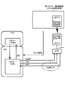
- control unit 10 includes a CPU (Central Processing Unit) 1011 as control means, a main memory (MEM-P) 1012 as main body side storage means, a north bridge (NB) 1013, and a south bridge (SB). ) 1014, AGP (Accelerated Graphics Port) bus 1015, ASIC (Application Specific Integrated Circuit) 1016, local memory (MEM-C) 1017, HD (Hard Disk) 1018, HDD (HardDisc network) Have.
- CPU Central Processing Unit
- MEM-P main memory
- NB north bridge
- SB south bridge
- AGP Accelerated Graphics Port
- ASIC Application Specific Integrated Circuit
- HD Hard Disk
- HDD HardDisc network
- the CPU 1011 processes and calculates data according to a program stored in the main memory 1012, and operates the image reading unit 11, the image forming unit 12, the paper feeding unit 13, the transfer unit 14, the fixing unit 15, and the paper discharging unit 16. To control.
- the main memory 1012 is a storage area of the control unit 10, and includes a ROM (Read Only Memory) 1012a and a RAM (Random Access Memory) 1012b.
- ROM Read Only Memory
- RAM Random Access Memory
- the ROM 1012a is a memory for storing programs and data for realizing each function of the control unit 10.
- the program stored in the ROM 1012a is configured to be recorded and provided on a computer-readable recording medium such as a CD-ROM, FD, CD-R, or DVD as an installable or executable file. You may do it.
- the RAM 1012b is used as a drawing memory or the like when developing programs and data and printing memory.
- the NB 1013 is a bridge for connecting the CPU 1011 to the MEM-P 1012, the SB 1014, and the AGP bus 1015.
- the SB 1014 is a bridge for connecting the NB 1013 to a PCI device and peripheral devices.
- the AGP bus 1015 is a bus interface for a graphics accelerator card that has been proposed to speed up graphic processing.
- the ASIC 1016 includes a PCI target and an AGP master, an arbiter (ARB) that forms the core of the ASIC 1016, a memory controller that controls the MEM-C 1017, and a plurality of DMACs (Direct Memory Access Controllers) that rotate image data using hardware logic. Composed.
- the ASIC 1016 is connected to an interface of USB (Universal Serial Bus) or an interface of IEEE 1394 (Institut of Electrical and Electronics Engineers 1394) via a PCI bus.
- MEM-C 1017 is a local memory used as a copy image buffer and a code buffer.
- the HD 1018 is a storage for accumulating image data, accumulating font data used during printing, and accumulating forms.
- the HDD 1019 controls reading or writing of data with respect to the HD 1018 according to the control of the CPU 1011.
- the network I / F 102 transmits / receives information to / from an external device such as an information processing apparatus via a communication network.
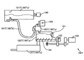
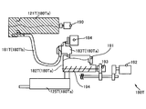
- replenishment toner conveyance path 180 will be described.
- the special color toner replenishment toner conveyance path 180T will be described.
- this description is also applicable to the process color toner replenishment toner conveyance paths 180C, 180M, 180Y, and 180K. is there.
- the special color toner replenishment toner conveyance path 180T includes a replenishment tube 181T connected to the toner bottle 121T, a diaphragm pump 183T as a conveyance unit, a sub hopper 182T as a temporary storage unit, a developing unit 125T, and the like.
- the replenishment toner conveyance path 180T is not limited to this form.
- the conveying screw in the toner bottle is driven by the driving force of the bottle driving motor 190.
- the toner enclosed in the toner bottle 121T is conveyed to the sub hopper 182T via the supply tube 181T based on detection information of the toner end sensor 191 that detects the toner amount of the sub hopper 182T.
- Diaphragm pump 183T as a conveying means for conveying toner generates a negative pressure by the driving force from diaphragm pump motor 184.
- the toner conveyed and stored in the sub hopper 182T is agitated by a replenishing screw 194 driven by a replenishing motor 192 via a replenishing clutch 193.
- the toner conveyed and stored in the sub hopper 182T is appropriately conveyed to the developing unit 125T.
- the case where the replenishment toner is conveyed to the developing unit 125T is, for example, a case where the toner amount of the developing unit 125T is equal to or less than a threshold value.
- the toner bottle 121T, the developing unit 125T, and the like constituting the replenishment toner conveyance path 180T have different useful lives. For this reason, in the conventional image forming apparatus of the type in which the replenishment toner transport path is unitized and replaced entirely, it is necessary to replace the entire replenishment toner transport path in accordance with the replacement timing of the parts having a short service life. As a result, the cost performance was extremely low.
- the toner bottle 121T is removed by being pulled out of the image forming apparatus 1 by the user, and is provided so as to be replaceable with a new toner bottle 121T. Yes.
- the diaphragm pump 183T and the sub hopper 182T that are integrally molded are removed from the image forming apparatus 1 by removing the screws, and can be replaced with a new diaphragm pump 183T and a sub hopper 182T.
- the developing unit 125T is removed by being pulled out from the image forming apparatus 1 along the slide rail, and is provided so as to be replaceable with a new developing unit 125T. That is, in this embodiment, as will be described later with reference to FIG. 7, all of the replenishment toner transport path 180T other than the replenishment tube 181T can be individually replaced.
- the replenishment toner conveyance path 180T can be individually replaced according to the useful life of each component, the cost can be improved as compared with the conventional replenishment toner conveyance path.
- the toner bottle 121T, the diaphragm pump 183T, the sub hopper 182T, the developing unit 125T, and the like that need to be replaced when the toner is replaced with a different type of toner in the replenishment toner transport path 180T are replaced with the first toner transport path 180Ta.
- the replenishment tube 181T that does not require replacement is used as the second toner transport path 180Tb.
- the supply tube 181T in the supply toner transport path 180T is configured not to be replaced. Therefore, when the replenishment toner conveyance path 180T is replaced with a part corresponding to a different type of toner, color mixture is caused. For example, when the first toner transport path 180Ta is replaced from the clear toner to the white toner, if no countermeasure is taken, the clear toner filled in the supply tube 181T and the replaced toner bottle 121 are replaced. The white toner is mixed.
- the image forming apparatus 1 of the present embodiment executes a cleaning process of the supply tube 181T by a cleaning unit.
- the cleaning process of the supply tube 181T is performed, for example, by suctioning from one end of the supply tube 181T with a cleaner as a cleaning means in a state where nothing is connected to both ends of the supply tube 181T. In this manner, the toner filled in the supply tube 181T can be cleaned.
- the cleaning unit is not limited to this mode.
- the fan that is directed toward one end of the supply tube 181T forcibly discharges the toner filled in the supply tube 181T from the other end. It is also good. Further, a cleaning unit that is not provided in the image forming apparatus 1 may be used.
- At least one of the two end portions of the supply tube 181T is facing upward in a state where the supply tube 181T is installed in the image forming apparatus 1.
- the toner filled in the interior of the two ends of the supply tube 181T is removed from the other of the two ends of the supply tube 181T. It can be prevented from falling into the image forming apparatus.
- the supply tube 181T can be equal to or longer than the service life of the main body of the image forming apparatus. Therefore, it is not necessary to replace the supply tube with a new supply tube. It may be replaced with a supply tube. Further, in the direct toner replenishment method in which the toner is directly replenished without going through the replenishment toner conveyance path from the toner bottle to the developing unit, cleaning of the replenishment toner conveyance path is unnecessary.
- an attachment / detachment state detection unit that enables detection of the attachment / detachment state of each component of the first toner conveyance path 180Ta and a toner type that enables detection of the toner type of each component of the first toner conveyance path 180Ta.
- the detection means will be described.
- the main body (BCU / IOB) performs data transmission / reception with ASAP_I / F.
- command data is transmitted / received (serial 9600 bps) between the M_Vodka (main body) and the CPU (RFID_RW) by ASAP_I / F. Then, the CPU (RFID_RW) is reset by the port reset (M_Vodka). Then, ASAP command analysis and data code conversion (mirror code conversion) are performed in the internal processing of the CPU (RFID_RW). Then, command / data transmission / reception (serial 106 kbps (13.56 MHz)) is performed between the CPU and the AFE (RFID_RW). Then, ASK modulation is performed using AFE (RFID_RW), and Read / Write (carrier wave 13.56 MHz, bit rate 26 kbps) is applied to the RF tag.
- ASK modulation is performed using AFE (RFID_RW)
- Read / Write carrier wave 13.56 MHz, bit rate 26 kbps
- the CPU 1011 serving as the control unit determines the presence / absence of detection information of the attachment / detachment state detection unit, that is, the presence / absence of communication information from the RFID tag attached to each component of the first toner conveyance path 180Ta.
- the attachment / detachment state of each component of the toner conveyance path 180Ta is detected.
- the attachment / detachment state detection means is determined based on the presence / absence of communication information from the RFID tag, but is not limited to this mode.
- the CPU 1011 determines whether or not each component of the first toner conveyance path 180Ta and a connection connector attached to the image forming apparatus main body side are connected, so that the toner bottle 121T and / or the replenishment toner conveyance is performed.
- the presence / absence of the attaching / detaching state of the means 180T and / or the developing unit 125T may be detected.
- the CPU 1011 as the control unit determines the toner type based on the detection information of the toner type detection unit, that is, the communication information from the RFID tag attached to each component of the first toner conveyance path 180Ta.
- the communication information from the RFID tag attached to each component of the first toner conveyance path 180Ta may be stored in the main memory 1012. In this case, from the information stored in the main memory 1012, the CPU 1011 can determine the toner type of each component of the first toner conveyance path 180Ta.
- the toner type detection means is not limited to this mode.
- a protrusion is formed on each component of the first toner transport path 180Ta so that the position differs depending on the toner type, and each component of the first toner transport path 180Ta is mounted on the image forming apparatus main body.
- the CPU 1011 may determine the toner type by detecting the position of the protrusion using an optical sensor.
- the user may recognize the toner type by reading a two-dimensional code such as a QR code (registered trademark) provided in each component of the first toner conveyance path 180Ta using a detector. .
- the activation flow of the RFID tag attached to each component constituting the first toner conveyance path 180Ta will be described with reference to FIG.
- the activation flow of the RFID tag attached to each component constituting the first toner conveyance path 180Ta has the same configuration, so the toner bottle 121T will be described, and the other components will be described. Omitted.
- step S10 execution of the RFID tag activation system is started to start RFID communication (step S10).
- step S11 it is determined whether or not the toner bottle lock detection sensor as the attachment / detachment state detecting means has released the lock of the toner bottle 121T (step S11). If the toner bottle lock detection sensor determines that the toner bottle 121T has been unlocked, the communication is interrupted, and the display unit 171 displays that the toner bottle is not set (step S13). Then, the RFID communication is terminated (step S14).
- step S21 determines whether an error has occurred.
- step S23 If it is determined that an error has occurred, it is determined whether or not the error has occurred three times in succession (step S23). If no error has occurred three times in succession, the process returns to step S22. On the other hand, if the error has occurred three times in succession, it is determined whether or not the error is a failure of the RFID chip (step S24). If it is determined that the error is a failure of the RFID chip, the communication is interrupted, a message indicating that the toner bottle is not set is displayed on the panel display unit 171 (step S13), and the RFID communication is terminated (step S14).
- step S31 it is determined whether or not the toner bottle lock detection sensor has unlocked the toner bottle 121T. If the toner bottle lock detection sensor determines that the toner bottle 121T has been unlocked, the communication is interrupted, a toner bottle not set is displayed on the panel display unit 171 (step S13), and the RFID communication is terminated (step S14). ).
- the toner bottle lock detection sensor determines that the toner bottle 121T has not been unlocked, it determines whether an error has occurred (step S32). If it is determined that an error has occurred, a serviceman call (SC) display corresponding to the generated error is displayed on the panel display unit 171 (step S33), and the RFID communication is terminated (step S14).
- SC serviceman call
- step S33 a normal display is displayed on the panel display unit 171 (step S33), and the RFID communication is terminated (step S14).
- step S22 If it is determined in step S22 that no error has occurred, the process proceeds to step S31, and the above-described routine from step S31 to step S14 is executed.
- toners of different toner types are used in the toner bottle 121T, the developing unit 125T, or the like for the same replenishing toner transport path 180T, toners of different toner types are mixed with each other. Then, all of the replenishment toner conveyance path 180T must be cleaned or replaced.
- the toner bottle 121T for clear toner and the developing unit 125T for white toner are used for the same replenishment toner transport path 180T, the clear toner and the white toner are mixed in the replenishment toner transport path, and the replenishment toner transport path All T must be cleaned or replaced.
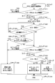
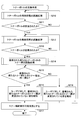
- the image forming apparatus 1 executes the following control.
- step S110 replacement of all the components of the first toner transport path 180Ta is started, and the process proceeds to a subroutine for the attachment / detachment state recognition process of each component of the first toner transport path 180Ta (step S110).
- FIG. 9 is a flowchart showing a subroutine of the attachment / detachment state recognition process for the components of the first toner conveyance path 180Ta.
- the attachment / detachment state recognition processing of the components of the first toner conveyance path 180Ta is started, and the CPU 1011 determines whether or not an RFID tag or an IC tag is mounted on the components of the first toner conveyance path 180Ta.
- Step S120 determines that an RFID tag or an IC tag is mounted on a component of the first toner conveyance path 180Ta
- the first toner conveyance is performed by communication between the RFID tag or the IC tag and the image forming apparatus main body.
- the attachment / detachment state of the component on the path 180Ta is recognized (step S121), the subroutine is terminated, and the process returns to the main flow.
- the image forming apparatus main body is electrically connected to the component of the first toner conveyance path 180Ta.
- the CPU 1011 determines whether or not the connector is mounted (step S122). If the CPU 1011 determines that a connector that is electrically connected to the image forming apparatus main body is mounted on a component of the first toner conveyance path 180Ta, the first connection is established by the electrical connection between the image forming apparatus main body and the connector.
- the attachment / detachment state of the components of the toner conveyance path 180Ta is recognized (step S123), the subroutine is terminated, and the process returns to the main flow.
- CPU 1011 determines whether or not is mounted (step S124). When the CPU 1011 determines that an optical sensor or a magnetic sensor is mounted on a component of the first toner transport path 180Ta, an output from the mounted optical sensor or magnetic sensor determines whether the first toner transport path 180Ta The attachment / detachment state of the component is recognized (step S125), the subroutine is terminated, and the process returns to the main flow.
- the panel display unit 171 confirms the attachment / detachment state of the component of the first toner conveyance path 180Ta. Display a prompt message. Then, when the operator inputs the attachment / detachment state of the components of the first toner conveyance path 180Ta recognized by visual observation or the like via the operation unit 172 or the like (step S126), the CPU 1011 ends the subroutine, and the main Return to the flow.
- step S111 the CPU 1011 or the operator determines whether or not the constituent elements of the first toner conveyance path 180Ta have been removed. If it is determined that the components of the first toner conveyance path 180Ta have not been removed, the process returns to step S110. On the other hand, if it is determined that the constituent elements of the first toner conveyance path 180Ta have been removed, the process proceeds to the cleaning process of the supply tube 181T (step S112).
- step S113 the process proceeds to a subroutine for recognizing the attachment / detachment state of the components of the first toner transport path 180Ta (step S113).
- step S114 the CPU 1011 or the operator determines whether or not the constituent elements of the first toner conveyance path 180Ta are attached. If it is determined that the components of the first toner conveyance path 180Ta are not attached, the process returns to step S113. On the other hand, if it is determined that the component of the first toner transport path 180Ta is attached, the subroutine for toner type recognition processing for the toner used in the newly installed component of the first toner transport path 180Ta is executed. Transfer and execute (step S115).
- FIG. 10 is a flowchart showing a subroutine of toner type recognition processing for toner used in the components of the first toner transport path 180Ta.
- toner type recognition processing for toner used in the components of the first toner conveyance path 180Ta is started, and whether or not an RFID tag, an IC tag, or the like is mounted on the components of the first toner conveyance path 180Ta. Is determined by the CPU 1011 (step S130).
- the CPU 1011 determines that an RFID tag or an IC tag is mounted on a component of the first toner conveyance path 180Ta
- the configuration of the first toner conveyance path 180Ta is based on information from the RFID tag or the IC tag.
- the type of toner used in the element is recognized (step S131), the subroutine is terminated, and the process returns to the main flow.
- step S132 determines whether or not an RFID tag or an IC tag is not mounted on a component of the first toner transport path 180Ta. If the CPU 1011 determines that an RFID tag or an IC tag is not mounted on a component of the first toner transport path 180Ta, is an optical sensor or a magnetic sensor mounted on the component of the first toner transport path 180Ta? The CPU 1011 determines whether or not (step S132). When the CPU 1011 determines that an optical sensor or a magnetic sensor is mounted on a component of the first toner transport path 180Ta, an output from the mounted optical sensor or magnetic sensor determines whether the first toner transport path 180Ta The toner type of the toner used in the component is recognized (step S1).
- the toner used by the constituent elements of the first toner conveyance path 180Ta is detected by the CPU 1011 by detecting the position of the protrusion formed so as to be different for each toner type by the optical sensor. Recognize the toner type. Then, the subroutine ends and the process returns to the main flow.
- the CPU 1011 determines that no optical sensor or magnetic sensor is mounted on the constituent elements of the first toner transport path 180Ta, the toner of toner used in the constituent elements of the first toner transport path 180Ta on the panel display unit 171. Display a message prompting you to confirm the species. Then, the operator visually checks the components and decal sheets of the first toner conveyance path 180Ta and recognizes the toner type of the toner used in the first toner conveyance path 180Ta. (Step S134), the CPU 1011 ends the subroutine and returns to the main flow.
- the toner bottle 121T the diaphragm pump 183T, the sub hopper 182T, the developing unit 125T, etc.
- the CPU 1011 or the operator determines whether or not all toner types are the same toner type (step S116). *
- step S117 When the toner types of the toners used in all the constituent elements of the newly mounted first toner transport path 180Ta are all the same toner type, all of the mounted new first toner transport path 180Ta By displaying a banner display, a window display, etc. on the panel display unit 171 that the toner types of the toners used in the constituent elements are all the same toner type, the user is notified (step S117). . Next, the toner supply from the toner bottle 121T is made executable (step S118), and the replacement operation of all the components of the first toner transport path 180Ta is completed.
- the user is notified of this fact. Even if not, problems such as color mixing do not occur. Therefore, in this case, it may be set in advance so as not to notify the user.
- the mounted new first toner transport By displaying on the panel display unit 171 that the toner type of the toner used in the component of the path 180Ta is not the same toner type with respect to at least one component, a panel display unit 171 is displayed. Notification is made (step S119), and the process returns to step S116. Note that the user is prompted to match the toner types by displaying on the panel display unit 171 a banner display, a window display, or the like indicating which component toner types do not match. Also good.
- reports by displaying a banner display, a window display, etc. on the panel display part 171 as an alerting
- the lamp may blink or light, or an alarm buzzer may be sounded.
- step S210 replacement of the toner bottle 121T is started, and the process proceeds to a subroutine for recognition / removal processing of the toner bottle 121T, that is, processing for recognizing the attachment / detachment state of components of the first toner transport path 180Ta (step S210).
- step S211 the CPU 1011 or the operator determines whether or not the toner bottle 121T has been removed. If it is determined that the toner bottle 121T has not been removed, the process returns to step S210. On the other hand, if it is determined that the toner bottle 121T has been removed, the process moves to a subroutine for the attachment / detachment state recognition process of the toner bottle 121T, that is, the attachment / detachment state recognition process for the component of the first toner transport path 180Ta (step S3). Step S212).
- the CPU 1011 or the operator determines whether or not the toner bottle 121T is attached (step S213). If it is determined that the toner bottle 121T is not attached, the process returns to step S112. On the other hand, if it is determined that the toner bottle 121T is mounted, the toner type recognition process for the new mounted toner bottle 121T, that is, the toner type recognition of the toner used in the components of the first toner transport path 180Ta. The process proceeds to a processing subroutine (step S214).
- the CPU 1011 or the operator determines whether or not, that is, whether or not the toner type is the same toner type before and after the replacement of the toner bottle 121T from the information stored in the main memory 1012 (step S215).
- step S 216 a message indicating that the toner type is the same toner type is displayed on the panel display unit as shown in FIG. By displaying on 171, the user is notified (step S 216).
- step S217 toner supply from the toner bottle 121T is made executable (step S217), and the replacement operation of the toner bottle 121T as a part of the first toner transport path 180Ta is finished.
- step S 118 a message indicating that the toner type is not the same toner type is displayed on the panel display unit as shown in FIG. By displaying on 171, the user is notified (step S 118), and the process returns to step S 115.
- a banner display or a window display that prompts the toner types to match is displayed, for example, as shown in FIG. It is necessary to replace it. Press OK if it has been replaced, and press NG if it has not been replaced.
- the toner bottle 121T When only the toner bottle 121T is replaced, the toner bottle 121T is replaced with a new toner bottle 121T whose content is the same toner type, and the same toner type is used for the other components of the first toner transport path 180Ta. Therefore, it is not necessary to execute the cleaning process for the supply tube 181T.
- the image forming apparatus 1 of the present embodiment by executing the above-described control, different toner types of toner are used in the toner bottle, the developing unit, and the like for the same replenishment toner conveyance path. Therefore, the toner bottle 121T can be individually replaced, and the toner bottle 121T can be replaced even during the printing operation. Therefore, it is possible to improve the printing efficiency as compared with the configuration in which the image forming station is replaced for each of the above-described image forming stations.
- the special color toner replenishment toner conveyance path 180T has been described.
- the process toner replenishment toner conveyance paths 180C, 180M, 180Y, and 180K may be applied.
- the image forming apparatus 1 since the image forming apparatus 1 according to the present embodiment includes the toner type detection unit, when the replenishment toner conveyance path 180T is replaced with a different toner type, it is used in all the components of the first replenishment toner conveyance path 180Ta. Since it is possible to detect whether the toner types of the toners to be used are the same toner type, it is possible to prevent color mixing of different types of toners.
- the first toner transport path 180Ta can be replaced individually, but does not require a highly rigid frame unlike the conventional image forming apparatus that replaces each image forming unit. The size can be reduced, and handling and replacement workability can be improved. *
- the first toner transport path 180Ta can be individually replaced according to the service life of each component, the first toner transport path 180Ta can have higher cost performance than the conventional replenishment toner transport path. . Moreover, since it has the cleaning means which cleans supply tube 181T, supply tube 181T can be used without replacing
- the replenishment toner conveyance path 180T includes the diaphragm pump 183, the position of the toner bottle 121T can be set regardless of the position of the developing unit 125T, so that the degree of freedom in design can be improved.
- the other of the two ends of the supply tube 181T is cleaned when the supply tube 181T is cleaned by the cleaning means. Therefore, it is possible to prevent the toner filled therein from falling into the image forming apparatus.
- the configuration in which the replenishment toner conveyance path includes the replenishment tube 181, the diaphragm pump 183, the sub hopper 182, and the developing unit 125 has been described, but is not limited to this aspect.
- the above-described flowchart is merely an example of a routine capable of exhibiting the operation of the present invention in the present embodiment, and other flowcharts are used as long as they are within a range in which the operation of the present invention can be exhibited. Needless to say, it is applicable.
- a replenishment toner transport path 180 including at least one of the plurality of connecting units 181 corresponding to one of the plurality of developing units 125 and one of the plurality of toner containers 121 as a component.
- the constituent elements constituting the replenishing toner transport path 180 can be individually replaced, and the same replenishing toner transport path 180 is configured with the toner type detecting means for detecting the toner type used in each of the constituent elements. Based on the information detected by the toner type detecting means when the constituent elements of the replenishing toner transport path 180 are exchanged, and informing means for informing whether or not the toner types used in all the constituent elements are the same.
- An image forming apparatus comprising control means 1011 for controlling the notification means.
- the control means 1011 informs the display means 171 that the toner type used in the component of the replenishment toner conveyance path 180 is not the same toner type when the toner type is not the same toner type for at least one component.
- An image forming apparatus that controls the notifying unit to display.
- the control unit 1011 controls the notification unit to display on the display unit 171 when the toner type of the toner used in the component is not the same before and after replacement of the component of the replenishment toner conveyance path 180.
- the replenishing toner transport path 180 further includes a transport unit 183 that transports toner from the toner container 121 to the developing unit 125 through the connection unit 181 as a constituent element.
- the replenishing toner transport path 180 further includes a temporary storage unit 182 that temporarily stores toner supplied from the toner container 121 to the developing unit 125 as a constituent element.
- the component of the replenishing toner conveyance path 180 is an information storage medium that stores information on the type of toner to be used
- the toner type detecting means detects information on toner types used in the constituent elements of the replenishing toner transport path 180 based on communication information with the information storage medium.
- the image forming apparatus characterized in that the control unit 1011 controls the notification unit based on information stored in the main body side storage unit 1012.
- an attachment / detachment state detection unit that detects an attachment / detachment state of a component of the replenishment toner conveyance path 180
- An image forming apparatus further comprising:
- the component of the replenishment toner conveyance path 180 includes an information storage medium
- the attachment / detachment state detection unit is configured to perform the replenishment toner conveyance path based on communication information with the information storage medium.
- An image forming apparatus comprising: detecting an attached / detached state of 180 components.
- the replenishment toner conveyance path 180 has a connector for electrically connecting the components of the replenishment toner conveyance path 180 and the image forming apparatus main body, and the attachment / detachment state detection means is based on the connection presence / absence information of the connector, An image forming apparatus that detects whether a component of the replenishment toner conveyance path 180 is attached or detached.
- the toner type detection unit detects information on a toner type used in a component of the replenishment toner transport path 180 based on an output of a sensor mounted on the component of the replenishment toner transport path 180.
- Image forming apparatus In the image forming apparatus according to any one of aspects A, B, C, D, E, F, G, and H, The toner type detection unit detects information on a toner type used in a component of the replenishment toner transport path 180 based on an output of a sensor mounted on the component of the replenishment toner transport path 180.
- An image forming apparatus further comprising: an attachment / detachment state detection unit that detects an attachment / detachment state of a component of the replenishment toner conveyance path 180.
- the control means 1011 includes: When an information storage medium is mounted on a component of the replenishment toner transport path 180, the attachment / detachment state of the component of the replenishment toner transport path 180 is detected based on communication information with the information storage medium.
- the attachment / detachment state detection method When an information storage medium is mounted on a component of the replenishment toner transport path 180, the attachment / detachment state of the component of the replenishment toner transport path 180 is detected based on communication information with the information storage medium.
- the control unit 1011 includes a sensor in a component of the replenishment toner transport path 180 when the connector is not mounted on a component of the replenishment toner transport path 180. And a mounting / dismounting state detecting method for detecting a mounting / dismounting state of components of the replenishing toner transport path 180 based on an output of the sensor.
- a toner type detection method for detecting a toner type of a constituent element of a replenishment toner conveyance path 180 used in an image forming apparatus comprising: a plurality of developing means 125 using toners of different toner types; and toners of different toner types
- a replenishment toner transport comprising at least a plurality of toner containers 121 to be accommodated, and a plurality of connecting means 181 respectively connecting each of the plurality of toner containers 121 and one of the corresponding plurality of developing means 125.
- the control unit 1011 is based on communication information with the information storage medium when an information storage medium is mounted on a component of the replenishment toner transport path 180. And detecting the toner type of toner used in the constituent elements of the replenishment toner conveyance path 180. And a toner type detection method.
- control unit 1011 is a component of the replenishment toner transport path 180 when the information storage medium is not mounted on a component of the replenishment toner transport path 180.
- toner bottle an example of a toner container
- Photosensitive drum an example of an image carrier
- Developing section an example of developing means
- Panel display unit an example of notification means
- Supply toner transport path 181
- Supply tube an example of connection means
- CPU an example of control means
- Main memory an example of main body storage means
Landscapes
- Physics & Mathematics (AREA)
- General Physics & Mathematics (AREA)
- Control Or Security For Electrophotography (AREA)
- Color Electrophotography (AREA)
- Dry Development In Electrophotography (AREA)
Abstract
Description
互いに異なるトナー種のトナーを用いる複数の現像手段と、 互いに異なるトナー種のトナーを収容する複数のトナー容器と、 前記複数のトナー容器のそれぞれと、対応する前記複数の現像手段の1つとを夫々接続する複数の接続手段と、を有し、 前記複数の現像手段の1つと、該複数の現像手段の1つに対応する前記複数のトナー容器の1つと、該複数の現像手段の1つ及び該複数のトナー容器の1つに対応する前記複数の接続手段の1つと、を少なくとも構成要素として備えている補給トナー搬送経路をトナー種毎に夫々具備する画像形成装置において、 前記補給トナー搬送経路の構成要素は、夫々個別に交換可能であり、 該構成要素で夫々使用されるトナー種を検出するトナー種検出手段と、 同一の補給トナー搬送経路を構成する全ての構成要素で夫々使用されるトナー種が同一か否かを報知する報知手段と、 前記補給トナー搬送経路の構成要素を交換する際に、前記トナー種検出手段による検出情報に基づいて、前記報知手段を制御する制御手段を備えたことを特徴とする。
、RFID通信を終了する(ステップS14)。
前記補給トナー搬送経路180を構成する構成要素は、夫々個別に交換可能であり、 該構成要素で夫々使用されるトナー種を検出するトナー種検出手段と、 同一の補給トナー搬送経路180を構成する全ての構成要素で夫々使用されるトナー種が同一か否かを報知する報知手段と、 前記補給トナー搬送経路180の構成要素を交換する際に、前記トナー種検出手段による検出情報に基づいて、前記報知手段を制御する制御手段1011を備えたことを特徴とする画像形成装置。
態様Aに記載の画像形成装置において、
前記報知手段は、視認可能な表示手段171を有することを特徴とする画像形成装置。
態様Bに記載の画像形成装置において、
前記制御手段1011は、前記補給トナー搬送経路180の構成要素で使用されるトナーのトナー種が、少なくとも1つの構成要素に関し同一のトナー種でない場合、同一のトナー種でないことを前記表示手段171に表示させるよう前記報知手段を制御することを特徴とする画像形成装置。
態様Cに記載の画像形成装置において、
前記表示手段171の表示は、トナー種を一致させるように促す表示であることを特徴
とする画像形成装置。
請求項Dに記載の画像形成装置において、
前記表示は、何れの構成要素のトナー種が一致していないのかを示す表示であることを特徴とする画像形成装置。
態様B、C、D、Eの何れかに記載の画像形成装置において、
前記制御手段1011は、前記補給トナー搬送経路180の構成要素の交換前後で、該構成要素で使用されるトナーのトナー種が同一でない場合、前記表示手段171に表示させるよう前記報知手段を制御することを特徴とする画像形成装置。
態様A、B、C、D、E、Fの何れかに記載の画像形成装置において、
前記補給トナー搬送経路180は、構成要素として、前記トナー容器121から前記現像手段125へ前記接続手段181を通してトナーを搬送させる搬送手段183を更に備えたことを特徴とする画像形成装置。
態様A、B、C、D、E、F、Gの何れかに記載の画像形成装置において、
前記補給トナー搬送経路180は、構成要素として、前記トナー容器121から前記現像手段125へ補給されるトナーを一時的に貯留する一時貯留部182を更に備えたことを特徴とする画像形成装置。
態様A、B、C、D、E、F、G、Hの何れかに記載の画像形成装置において、 前記補給トナー搬送経路180の構成要素は、使用するトナー種の情報を記憶した情報記憶媒体を有し、 前記トナー種検出手段は、該情報記憶媒体との通信情報に基づき、該補給トナー搬送経路180の構成要素で使用されるトナー種の情報を検出することを特徴とする画像形成装置。
態様Iに記載の画像形成装置において、
前記トナー種検出手段による検出情報を記憶する本体側記憶手段1012を有し、
前記制御手段1011は、該本体側記憶手段1012の記憶情報に基づいて、前記報知手段を制御することを特徴とする画像形成装置。
態様A、B、C、D、E、F、G、H、I、Jの何れかに記載の画像形成装置において、 前記補給トナー搬送経路180の構成要素の着脱状態を検出する着脱状態検出手段を更に備えたことを特徴とする画像形成装置。
態様Kに記載の画像形成装置において、 前記補給トナー搬送経路180の構成要素は情報記憶媒体を有し、 前記着脱状態検出手段は、前記情報記憶媒体との通信情報に基づき、該補給トナー搬送経路180の構成要素の着脱状態を検出することを特徴とする画像形成装置。
態様Kに記載の画像形成装置において、
前記補給トナー搬送経路180は、該補給トナー搬送経路180の構成要素と画像形成装置本体とを電気的に接続するコネクタを有し、 前記着脱状態検出手段は、該コネクタの接続有無情報に基づき、該補給トナー搬送経路180の構成要素の着脱状態を検出することを特徴とする画像形成装置。
態様A、B、C、D、E、F、G、Hの何れかに記載の画像形成装置において、
前記トナー種検出手段は、前記補給トナー搬送経路180の構成要素に搭載されたセンサの出力に基づき、該補給トナー搬送経路180の構成要素で使用されるトナー種の情報を検出することを特徴とする画像形成装置。
態様Nに記載の画像形成装置において、
前記補給トナー搬送経路180の構成要素の着脱状態を検出する着脱状態検出手段を更に備えたことを特徴とする画像形成装置。
態様Oに記載の画像形成装置において、
前記着脱状態検出手段は、前記センサの出力に基づき、該補給トナー搬送経路180の構成要素の着脱状態を検出することを特徴とする画像形成装置。
態様A、B、C、D、E、F、G、H、I、J、K、L、M、N、O、Pの何れかに記載の画像形成装置において、 前記接続手段181を清掃する清掃手段を有し、
前記補給トナー搬送経路180の構成要素を交換する際に、該接続手段181は、交換されずに該清掃手段によって清掃されることを特徴とする画像形成装置。
態様Qに記載の画像形成装置において、
前記接続手段181の2つの端部のうち少なくとも一方は、画像形成装置に設置された状態で、上方に向いていることを特徴とする画像形成装置。
画像形成装置に用いられる補給トナー搬送経路180の構成要素の着脱状態を検出する着脱状態検出方法であって、 トナーを収容するトナー容器121と、前記トナー容器121トナーに収容されているトナーを用いる現像手段125と、該トナー容器121と該現像手段125を接続する接続手段181と、を少なくとも構成要素として備える補給トナー搬送経路180の着脱状態を検出する着脱状態検出方法において、 制御手段1011は、前記補給トナー搬送経路180の構成要素に情報記憶媒体が搭載されている場合に、該情報記憶媒体との通信情報に基づき、該補給トナー搬送経路180の構成要素の着脱状態を検出することを特徴とする着脱状態検出方法。
態様Sに記載の着脱状態検出方法において、
前記制御手段1011は、前記補給トナー搬送経路180の構成要素に前記情報記憶媒体が搭載されていない場合であって、前記補給トナー搬送経路180の構成要素にコネクタが搭載されている場合に、該コネクタの接続有無情報に基づき、該補給トナー搬送経路180の構成要素の着脱状態を検出することを特徴とする着脱状態検出方法。
態様Tに記載の着脱状態検出方法において、 前記制御手段1011は、前記補給トナー搬送経路180の構成要素に前記コネクタが搭載されていない場合であって、前記補給トナー搬送経路180の構成要素にセンサが搭載されている場合に、該センサの出力に基づき、該補給トナー搬送経路180の構成要素の着脱状態を検出することを特徴とする着脱状態検出方法。
態様Uに記載の着脱状態検出方法において、 前記補給トナー搬送経路180の構成要素に前記センサが搭載されていない場合に、作業者が前記補給トナー搬送経路180の構成要素の着脱状態を認識し、画像形成装置に指示することで、前記制御手段1011は、該補給トナー搬送経路180の構成要素の着脱状態を検出することを特徴とする着脱状態検出方法。
画像形成装置に用いられる補給トナー搬送経路180の構成要素のトナー種を検出するトナー種検出方法であって、 互いに異なるトナー種のトナーを用いる複数の現像手段125と、 互いに異なるトナー種のトナーを収容する複数のトナー容器121と、 前記複数のトナー容器121のそれぞれと、対応する前記複数の現像手段125の1つとを夫々接続する複数の接続手段181と、を少なくとも構成要素として備える補給トナー搬送経路180のトナー種を検出するトナー種検出方法において、 制御手段1011は、前記補給トナー搬送経路180の構成要素に情報記憶媒体が搭載されている場合に、該情報記憶媒体との通信情報に基づき、該補給トナー搬送経路180の構成要素で使用されるトナーのトナー種を検出することを特徴とするトナー種検出方法。
態様Wに記載のトナー種検出方法において、 前記制御手段1011は、前記補給トナー搬送経路180の構成要素に前記情報記憶媒体が搭載されていない場合であって、前記補給トナー搬送経路180の構成要素にセンサが搭載されている場合に、該センサの出力に基づき、該補給トナー搬送経路180の構成要素で使用されるトナーのトナー種を検出することを特徴とするトナー種検出方法。
態様Xに記載のトナー種検出方法において、
前記補給トナー搬送経路180の構成要素に前記センサが搭載されていない場合に、
作業者が前記補給トナー搬送経路180の構成要素の着脱状態を認識し、画像形成装置に指示することで、前記制御手段1011は、該補給トナー搬送経路180の構成要素で使用されるトナーのトナー種を検出することを特徴とするトナー種検出方法。
122 感光体ドラム(像担持体の一例)
125 現像部(現像手段の一例)
171 パネル表示部(報知手段の一例)
180 補給トナー搬送経路
181 補給チューブ(接続手段の一例)
1011 CPU(制御手段の一例)
1012 メインメモリ(本体側記憶手段の一例)
Claims (21)
- 互いに異なるトナー種のトナーを用いる複数の現像手段と、
互いに異なるトナー種のトナーを収容する複数のトナー容器と、
前記複数のトナー容器のそれぞれと、対応する前記複数の現像手段の1つとを夫々接続する複数の接続手段と、を有し、 前記複数の現像手段の1つと、該複数の現像手段の1つに対応する前記複数のトナー容器の1つと、該複数の現像手段の1つ及び該複数のトナー容器の1つに対応する前記複数の接続手段の1つと、を少なくとも構成要素として備えている補給トナー搬送経路をトナー種毎に夫々具備する画像形成装置において、 前記補給トナー搬送経路の構成要素は、夫々個別に交換可能であり、 該構成要素で夫々使用されるトナー種を検出するトナー種検出手段と、 同一の補給トナー搬送経路を構成する全ての構成要素で夫々使用されるトナー種が同一か否かを報知する報知手段と、 前記補給トナー搬送経路の構成要素を交換する際に、前記トナー種検出手段による検出情報に基づいて、前記報知手段を制御する制御手段を備えたこと特徴とする画像形成装置。 - 請求項1に記載の画像形成装置において、
前記報知手段は、視認可能な表示手段を有することを特徴とする画像形成装置。 - 請求項2に記載の画像形成装置において、
前記制御手段は、前記補給トナー搬送経路の構成要素で使用されるトナーのトナー種が、少なくとも1つの構成要素に関し同一のトナー種でない場合、同一のトナー種でないことを前記表示手段に表示させるよう前記報知手段を制御することを特徴とする画像形成装置。 - 請求項3に記載の画像形成装置において、
前記表示手段の表示は、トナー種を一致させるように促す表示であることを特徴とする画像形成装置。 - 請求項4に記載の画像形成装置において、
前記表示は、何れの構成要素のトナー種が一致していないのかを示す表示であることを特徴とする画像形成装置。 - 請求項2に記載の画像形成装置において、
前記制御手段は、前記補給トナー搬送経路の構成要素の交換前後で、該構成要素で使用されるトナーのトナー種が同一でない場合、前記表示手段に表示させるよう前記報知手段を制御することを特徴とする画像形成装置。 - 請求項6に記載の画像形成装置において、
前記表示手段の表示は、トナー種を一致させるように促す表示であることを特徴とする画像形成装置。 - 請求項1に記載の画像形成装置において、
前記補給トナー搬送経路は、構成要素として、前記トナー容器から前記現像手段へ前記接続手段を通してトナーを搬送させる搬送手段を更に備えたことを特徴とする画像形成装置。 - 請求項1に記載の画像形成装置において、
前記補給トナー搬送経路は、構成要素として、前記トナー容器から前記現像手段へ補給されるトナーを一時的に貯留する一時貯留部を更に備えたことを特徴とする画像形成装置
。 - 請求項1~9の何れかに記載の画像形成装置において、
前記補給トナー搬送経路の構成要素は、使用するトナー種の情報を記憶した情報記憶媒体を有し、 前記トナー種検出手段は、該情報記憶媒体との通信情報に基づき、該補給トナー搬送経路の構成要素で使用されるトナー種の情報を検出することを特徴とする画像形成装置。 - 請求項10に記載の画像形成装置において、
前記トナー種検出手段による検出情報を記憶する本体側記憶手段を有し、
前記制御手段は、該本体側記憶手段の記憶情報に基づいて、前記報知手段を制御することを特徴とする画像形成装置。 - 請求項10に記載の画像形成装置において、
前記補給トナー搬送経路の構成要素の着脱状態を検出する着脱状態検出手段を更に備えたことを特徴とする画像形成装置。 - 請求項12に記載の画像形成装置において、
前記着脱状態検出手段は、前記情報記憶媒体との通信情報に基づき、該補給トナー搬送経路の構成要素の着脱状態を検出することを特徴とする画像形成装置。 - 請求項12に記載の画像形成装置において、
前記補給トナー搬送経路は、該補給トナー搬送経路の構成要素と画像形成装置本体とを電気的に接続するコネクタを有し、 前記着脱状態検出手段は、該コネクタの接続有無情報に基づき、該補給トナー搬送経路の構成要素の着脱状態を検出することを特徴とする画像形成装置。 - 請求項12に記載の画像形成装置において、
前記接続手段を清掃する清掃手段を有し、 前記補給トナー搬送経路の構成要素を交換する際に、該接続手段は、交換されずに該清掃手段によって清掃されることを特徴とする画像形成装置。 - 請求項15に記載の画像形成装置において、
前記接続手段の2つの端部のうち少なくとも一方は、画像形成装置に設置された状態で、上方に向いていることを特徴とする画像形成装置。 - 請求項1~9の何れかに記載の画像形成装置において、
前記トナー種検出手段は、前記補給トナー搬送経路の構成要素に搭載されたセンサの出力に基づき、該補給トナー搬送経路の構成要素で使用されるトナー種の情報を検出することを特徴とする画像形成装置。 - 請求項17に記載の画像形成装置において、
前記補給トナー搬送経路の構成要素の着脱状態を検出する着脱状態検出手段を更に備えたことを特徴とする画像形成装置。 - 請求項18に記載の画像形成装置において、
前記着脱状態検出手段は、前記センサの出力に基づき、該補給トナー搬送経路の構成要素の着脱状態を検出することを特徴とする画像形成装置。 - 請求項18に記載の画像形成装置において、
前記接続手段を清掃する清掃手段を有し、 前記補給トナー搬送経路の構成要素を交換する際に、該接続手段は、交換されずに該清掃手段によって清掃されることを特徴とする画像形成装置。 - 請求項20に記載の画像形成装置において、 前記接続手段の2つの端部のうち少なくとも一方は、画像形成装置に設置された状態で、上方に向いていることを特徴とする画像形成装置。
Priority Applications (4)
| Application Number | Priority Date | Filing Date | Title |
|---|---|---|---|
| CN201480072343.7A CN105874390A (zh) | 2014-01-10 | 2014-12-05 | 图像形成装置 |
| EP14878079.4A EP3093714A4 (en) | 2014-01-10 | 2014-12-05 | Image forming device |
| JP2015556737A JPWO2015104931A1 (ja) | 2014-01-10 | 2014-12-05 | 画像形成装置 |
| US15/202,024 US20160313668A1 (en) | 2014-01-10 | 2016-07-05 | Image forming apparatus |
Applications Claiming Priority (4)
| Application Number | Priority Date | Filing Date | Title |
|---|---|---|---|
| JP2014003288 | 2014-01-10 | ||
| JP2014-003288 | 2014-01-10 | ||
| JP2014181092 | 2014-09-05 | ||
| JP2014-181092 | 2014-09-05 |
Related Child Applications (1)
| Application Number | Title | Priority Date | Filing Date |
|---|---|---|---|
| US15/202,024 Continuation US20160313668A1 (en) | 2014-01-10 | 2016-07-05 | Image forming apparatus |
Publications (1)
| Publication Number | Publication Date |
|---|---|
| WO2015104931A1 true WO2015104931A1 (ja) | 2015-07-16 |
Family
ID=53523769
Family Applications (1)
| Application Number | Title | Priority Date | Filing Date |
|---|---|---|---|
| PCT/JP2014/082303 Ceased WO2015104931A1 (ja) | 2014-01-10 | 2014-12-05 | 画像形成装置 |
Country Status (5)
| Country | Link |
|---|---|
| US (1) | US20160313668A1 (ja) |
| EP (1) | EP3093714A4 (ja) |
| JP (1) | JPWO2015104931A1 (ja) |
| CN (1) | CN105874390A (ja) |
| WO (1) | WO2015104931A1 (ja) |
Cited By (2)
| Publication number | Priority date | Publication date | Assignee | Title |
|---|---|---|---|---|
| US9588460B2 (en) | 2014-11-13 | 2017-03-07 | Ricoh Company, Ltd. | Image forming apparatus |
| JP2021189371A (ja) * | 2020-06-03 | 2021-12-13 | 株式会社リコー | 画像形成装置、画像形成方法、及びプログラム |
Families Citing this family (4)
| Publication number | Priority date | Publication date | Assignee | Title |
|---|---|---|---|---|
| EP3828637A1 (en) * | 2019-11-26 | 2021-06-02 | Ricoh Company, Ltd. | Image forming apparatus |
| JP2023095227A (ja) | 2021-12-24 | 2023-07-06 | 株式会社リコー | 画像形成装置 |
| JP2024075250A (ja) | 2022-11-22 | 2024-06-03 | 株式会社リコー | 画像形成装置、画像形成方法、及び、印刷物 |
| JP2024077445A (ja) | 2022-11-28 | 2024-06-07 | 株式会社リコー | 出力機器、出力システム、出力方法、プログラム、端末装置 |
Citations (7)
| Publication number | Priority date | Publication date | Assignee | Title |
|---|---|---|---|---|
| JPS6385771A (ja) * | 1986-09-30 | 1988-04-16 | Mita Ind Co Ltd | 複写装置 |
| JP2007232857A (ja) * | 2006-02-28 | 2007-09-13 | Matsushita Electric Ind Co Ltd | 現像装置及びこれを備えたカラー画像形成装置 |
| JP2008076436A (ja) * | 2006-09-19 | 2008-04-03 | Ricoh Co Ltd | 粉体搬送装置、及び画像形成装置 |
| JP4321583B2 (ja) | 2006-12-15 | 2009-08-26 | コニカミノルタビジネステクノロジーズ株式会社 | 画像形成装置、画像形成方法およびコンピュータプログラム |
| JP2010066473A (ja) | 2008-09-10 | 2010-03-25 | Ricoh Co Ltd | 画像形成装置 |
| JP2011191626A (ja) * | 2010-03-16 | 2011-09-29 | Casio Electronics Co Ltd | 画像形成装置 |
| JP2011237794A (ja) * | 2010-05-04 | 2011-11-24 | Toshiba Corp | 画像形成装置及び画像形成方法 |
Family Cites Families (10)
| Publication number | Priority date | Publication date | Assignee | Title |
|---|---|---|---|---|
| US5184181A (en) * | 1986-09-24 | 1993-02-02 | Mita Industrial Co., Ltd. | Cartridge discriminating system |
| US4963939A (en) * | 1986-09-24 | 1990-10-16 | Mita Industrial Co., Ltd. | Cartridge discriminating system |
| EP1589384B1 (en) * | 2004-04-23 | 2020-01-08 | Ricoh Company, Ltd. | Developer container |
| JP4498122B2 (ja) * | 2004-12-20 | 2010-07-07 | キヤノン株式会社 | 画像形成方法 |
| JP2006227371A (ja) * | 2005-02-18 | 2006-08-31 | Ricoh Printing Systems Ltd | トナー補給装置 |
| DE102006017846B3 (de) * | 2006-04-18 | 2008-01-03 | OCé PRINTING SYSTEMS GMBH | Elektrografische Druckeinrichtung aus mindestens einem Druckwerk mit einer Mehrzahl von Entwicklerstationen |
| US8150299B2 (en) * | 2007-12-10 | 2012-04-03 | Kabushiki Kaisha Toshiba | Toner supplying apparatus and toner supplying method for image forming apparatus |
| US8295742B2 (en) * | 2008-11-10 | 2012-10-23 | Ricoh Company, Limited | Powder container, powder supplying device, and image forming apparatus |
| CN101738908B (zh) * | 2008-11-10 | 2013-08-14 | 株式会社理光 | 粉末容器、粉末供应装置以及成像设备 |
| JP2013190612A (ja) * | 2012-03-14 | 2013-09-26 | Ricoh Co Ltd | トナー補給装置およびこのトナー補給装置を備えた画像形成装置 |
-
2014
- 2014-12-05 EP EP14878079.4A patent/EP3093714A4/en not_active Withdrawn
- 2014-12-05 CN CN201480072343.7A patent/CN105874390A/zh active Pending
- 2014-12-05 JP JP2015556737A patent/JPWO2015104931A1/ja active Pending
- 2014-12-05 WO PCT/JP2014/082303 patent/WO2015104931A1/ja not_active Ceased
-
2016
- 2016-07-05 US US15/202,024 patent/US20160313668A1/en not_active Abandoned
Patent Citations (7)
| Publication number | Priority date | Publication date | Assignee | Title |
|---|---|---|---|---|
| JPS6385771A (ja) * | 1986-09-30 | 1988-04-16 | Mita Ind Co Ltd | 複写装置 |
| JP2007232857A (ja) * | 2006-02-28 | 2007-09-13 | Matsushita Electric Ind Co Ltd | 現像装置及びこれを備えたカラー画像形成装置 |
| JP2008076436A (ja) * | 2006-09-19 | 2008-04-03 | Ricoh Co Ltd | 粉体搬送装置、及び画像形成装置 |
| JP4321583B2 (ja) | 2006-12-15 | 2009-08-26 | コニカミノルタビジネステクノロジーズ株式会社 | 画像形成装置、画像形成方法およびコンピュータプログラム |
| JP2010066473A (ja) | 2008-09-10 | 2010-03-25 | Ricoh Co Ltd | 画像形成装置 |
| JP2011191626A (ja) * | 2010-03-16 | 2011-09-29 | Casio Electronics Co Ltd | 画像形成装置 |
| JP2011237794A (ja) * | 2010-05-04 | 2011-11-24 | Toshiba Corp | 画像形成装置及び画像形成方法 |
Non-Patent Citations (1)
| Title |
|---|
| See also references of EP3093714A4 |
Cited By (3)
| Publication number | Priority date | Publication date | Assignee | Title |
|---|---|---|---|---|
| US9588460B2 (en) | 2014-11-13 | 2017-03-07 | Ricoh Company, Ltd. | Image forming apparatus |
| JP2021189371A (ja) * | 2020-06-03 | 2021-12-13 | 株式会社リコー | 画像形成装置、画像形成方法、及びプログラム |
| JP7447682B2 (ja) | 2020-06-03 | 2024-03-12 | 株式会社リコー | 画像形成装置、画像形成方法、及びプログラム |
Also Published As
| Publication number | Publication date |
|---|---|
| EP3093714A1 (en) | 2016-11-16 |
| EP3093714A4 (en) | 2017-07-26 |
| JPWO2015104931A1 (ja) | 2017-03-23 |
| US20160313668A1 (en) | 2016-10-27 |
| CN105874390A (zh) | 2016-08-17 |
Similar Documents
| Publication | Publication Date | Title |
|---|---|---|
| CN105607438B (zh) | 图像形成装置 | |
| US9239542B2 (en) | Image forming apparatus | |
| JP6201492B2 (ja) | 画像形成装置 | |
| WO2015104931A1 (ja) | 画像形成装置 | |
| US8456681B2 (en) | Image processing apparatus, image forming apparatus, and storage medium storing program | |
| JP6700817B2 (ja) | 画像形成装置、画像形成装置の制御方法 | |
| US10845748B2 (en) | Image forming apparatus and control method to check consumable part consumption | |
| CN101446786A (zh) | 图像形成装置及其方法 | |
| US9684259B2 (en) | Image forming apparatus | |
| JP5265477B2 (ja) | 画像形成装置 | |
| GB2561442A (en) | Image forming apparatus | |
| US8929796B2 (en) | Recovery toner container and image forming apparatus | |
| JP2002123051A (ja) | 画像形成装置 | |
| US7630654B2 (en) | Printing apparatus | |
| US10133224B2 (en) | Image formation apparatus and error notification method | |
| JP5677907B2 (ja) | 画像形成装置 | |
| US20250328102A1 (en) | Image forming system that manages consumption information of valid consumable item among plurality of consumable items | |
| JP5450367B2 (ja) | 画像形成装置 | |
| JP2009163099A (ja) | 画像形成装置 | |
| JP5244741B2 (ja) | 画像形成装置 | |
| JP2017167472A (ja) | 画像形成装置 | |
| JP2024171389A (ja) | 画像形成装置 | |
| JP2014119515A (ja) | 画像形成装置 | |
| JP2006162965A (ja) | 画像形成装置及び廃トナー回収容器 | |
| JP2013205463A (ja) | 画像形成装置 |
Legal Events
| Date | Code | Title | Description |
|---|---|---|---|
| 121 | Ep: the epo has been informed by wipo that ep was designated in this application |
Ref document number: 14878079 Country of ref document: EP Kind code of ref document: A1 |
|
| ENP | Entry into the national phase |
Ref document number: 2015556737 Country of ref document: JP Kind code of ref document: A |
|
| REEP | Request for entry into the european phase |
Ref document number: 2014878079 Country of ref document: EP |
|
| WWE | Wipo information: entry into national phase |
Ref document number: 2014878079 Country of ref document: EP |
|
| NENP | Non-entry into the national phase |
Ref country code: DE |