WO2015105202A1 - Dispositif de production de poussée - Google Patents
Dispositif de production de poussée Download PDFInfo
- Publication number
- WO2015105202A1 WO2015105202A1 PCT/JP2015/051742 JP2015051742W WO2015105202A1 WO 2015105202 A1 WO2015105202 A1 WO 2015105202A1 JP 2015051742 W JP2015051742 W JP 2015051742W WO 2015105202 A1 WO2015105202 A1 WO 2015105202A1
- Authority
- WO
- WIPO (PCT)
- Prior art keywords
- rotor
- blades
- blade
- power
- rotating
- Prior art date
- Legal status (The legal status is an assumption and is not a legal conclusion. Google has not performed a legal analysis and makes no representation as to the accuracy of the status listed.)
- Ceased
Links
Images





Classifications
-
- F—MECHANICAL ENGINEERING; LIGHTING; HEATING; WEAPONS; BLASTING
- F04—POSITIVE - DISPLACEMENT MACHINES FOR LIQUIDS; PUMPS FOR LIQUIDS OR ELASTIC FLUIDS
- F04D—NON-POSITIVE-DISPLACEMENT PUMPS
- F04D29/00—Details, component parts, or accessories
- F04D29/05—Shafts or bearings, or assemblies thereof, specially adapted for elastic fluid pumps
- F04D29/053—Shafts
-
- F—MECHANICAL ENGINEERING; LIGHTING; HEATING; WEAPONS; BLASTING
- F04—POSITIVE - DISPLACEMENT MACHINES FOR LIQUIDS; PUMPS FOR LIQUIDS OR ELASTIC FLUIDS
- F04D—NON-POSITIVE-DISPLACEMENT PUMPS
- F04D19/00—Axial-flow pumps
- F04D19/02—Multi-stage pumps
- F04D19/024—Multi-stage pumps with contrarotating parts
-
- F—MECHANICAL ENGINEERING; LIGHTING; HEATING; WEAPONS; BLASTING
- F04—POSITIVE - DISPLACEMENT MACHINES FOR LIQUIDS; PUMPS FOR LIQUIDS OR ELASTIC FLUIDS
- F04D—NON-POSITIVE-DISPLACEMENT PUMPS
- F04D25/00—Pumping installations or systems
- F04D25/02—Units comprising pumps and their driving means
Definitions
- the present invention relates to a thrust generating device, and the thrust generating device of the present invention is manufactured as a heavy industry-related product only with the permission of the United States government and the Japanese government which is an ally of the United States in the country of the inventor. About what is possible.
- each of the individual parts or individual parts constituting the part that sends the flow from the front to the rear by the rotation of the rotating body to power the fluid or “blades”, or “Wings” or “rotor blades”, and in this specification, “blades” or “wings” or “rotor blades” are collectively referred to as “blades” and are described below.
- Rotating part of an axial flow compressor constituting a rotating shaft or rotating wheel for mounting a plurality of the blades or blades or rotor blades described above, or for integrating a plurality of the blades or blades described above.
- An axial flow compressor in which a blade or blade or rotor blade and a disk or ring are fixed or integrally structured is referred to as a “rotor” or “moving blade”.
- a blade or blade or rotor blade and a disk or ring are fixed or integrally structured
- moving blade In an axial flow compressor, the aforementioned moving blades rotate to send a flow from the front to the rear, and by passing the flow, the flow is adjusted and fixed to send the flow backward with pressure.
- “Blade” or “wing” is referred to as “stator vane” or “stator vane”.
- “stator vane” or “stator vane” is collectively referred to as “stator vane” as described below.
- a plurality of "static blades” are arranged radially around the rotation axis so as to be concentric, and the fixed portion is referred to as a "stator”.
- a cylindrical structure having a suction hole and an exhaust hole in the front-rear direction of the rotating shaft of the above-described rotating body, which supports internal components or is mounted with a stationary blade, is referred to as a “casing”.
- the compressor casing constitutes a “stator”, and the combustor casing comprises an outer cylinder casing and an inner cylinder liner inside the casing.
- the combustor casing comprises an outer cylinder casing and an inner cylinder liner inside the casing.
- nozzle a stationary blade
- An axial flow compressor is a compressor in which air flows in parallel to a rotation axis, and is composed of rotor blades (rotary blades) on the rotating body side and vanes of stationary blades (fixed blades) on the engine body side (Non-Patent Document 38). (Pages 38 to 41, pages 102 to 106 and pages 112 to 116 of Non-Patent Document 40, pages 233 to 331 of Non-Patent Document 39, etc.).
- a conventional axial compressor has a multistage structure in which a plurality of moving blade rows and stationary blade rows are alternately arranged in the axial direction, and usually a set of this moving blade row and stationary blade row is called a unit,
- the conventional axial flow compressor includes a moving blade that sends a flow from the front to the rear as the rotating body having the blades rotates, and a suction hole and a suction hole in the front-rear direction of the rotation shaft of the axial flow compressor.
- Non-Patent Document 32 Non-Patent Document 36, Non-Patent Document 37, Non-Patent Document 38, Non-Patent Document 39, Non-Patent Document 40, and Non-Patent Document 41
- the air flows along the blade surface of the compressor. However, when the air flow rate is small, the air does not flow along the blade surface and separation occurs.
- ordinary axial flow compressors are equipped with a device that extracts part of the air from the middle stage of the compressor, increasing the air flow rate through the compressor and reducing the angle of attack to prevent stalling. It was. Further, a guide vane at the compressor inlet of a method (variable vane) in which the vane of the compressor is variable (pages 138 and 140 of Non-Patent Document 38, etc.) and the vane angle is changed along the air flow. In addition, there are a method in which the angle of attack with respect to the moving blade is made appropriate by changing the mounting angle of the first several stages of the stationary blades, and a method of dividing into two shafts, a high pressure shaft and a low pressure shaft.
- a conventional moving blade (fan part, compression part, etc.) or stationary blade uses a metal or a composite material (see pages 112 to 116 of Non-Patent Document 40), and a conventional moving blade (fan) Part, compression part, etc.) is a blisk structure in which a blade part (described as a moving blade in Non-Patent Document 40) and a disk part (or a rotor part) are integrated, or a blade part and a disk part.
- a blade part described as a moving blade in Non-Patent Document 40
- a disk part or a rotor part
- There are various structures such as a dovetail structure separated from each other. The material, structure, shape, etc.
- Non-Patent Document 40 pages 112 to 116, Non-Patent Document 38, pages 52 and 56, etc.
- the low pressure compressor blade (fan part) Titanium alloys (lightweight, high-strength materials that are resistant to corrosion and erosion) are mainly used, and metal-based composites of metals such as titanium alloys and silicon carbide fibers have been studied.
- High pressure compressor Titanium alloy, heat-resistant titanium alloy and nickel alloy (with creep resistance, high thermal conductivity, low thermal expansion coefficient, environmental resistance (corrosion resistance, oxidation resistance, etc.), etc. Use).
- the vane of the low-pressure compressor is Such as stainless steel and weldable titanium alloy
- the compressor disk Such as stainless steel and titanium alloy
- the liner of the combustor Special superalloys with high nickel and chromium content (high strength, creep resistance, high thermal conductivity, low thermal expansion, oxidation resistance, etc.), etc.
- the turbine blades and Superalloys (those with high creep resistance, high breaking strength, high fatigue strength, high thermal conductivity, low thermal expansion, high temperature corrosion resistance, oxidation resistance, etc.), etc.
- Turbine disc superalloy Casings Titanium alloys and nickel alloys for compressor casings, superalloys for combustor and turbine casings, fan casings using iron, titanium, aluminum and aramid fibers, epoxy resins and carbon fibers Using composite materials (hardness (hardness of deformation) and strength) Various materials were used.
- gas turbine machining methods include precision casting, unidirectional solidification / single crystal casting, laser beam machining, electron beam machining, electrical discharge machining, chemical milling, electrolytic machining and coating.
- Non-Patent Document 38 In order to extend the life of parts due to the severe usage environment, corrosion resistant coatings are applied to compressors and turbines, heat resistant coatings are applied to turbines, and thermal barrier coatings using ceramics are applied to combustors and turbines.
- Non-Patent Document 38 A composite material of epoxy resin reinforced with carbon fiber or boron fiber for fan blades, etc., using a metal cover on the front edge of the wing and using a three-dimensional fabric in the thickness direction of the blade, or material for high temperature parts
- new materials such as those using a metal matrix composite MMC, a ceramic matrix composite CMC, an intermetallic compound alloy, etc. are being developed. Ceramic materials are silicon nitride and silicon carbide, and various technological innovations are still in progress.
- the bearing “Mechanical element that supports the rotating shaft and smoothly rotates the shaft” is a rolling bearing “ball or roller is inserted between the outer ring and the inner ring to reduce the friction by rolling contact. Bearings. ”Sliding bearings“ Bearings where the bearing surface and the journal are in surface contact. ”(See Non-Patent Document 4), etc.
- rolling bearings mainly used for aviation, and molybdenum-based high-speed steel is used.
- Non-Patent Document 38 pages 542 to 547 of Non-Patent Document 39, Non-Patent Document 30, Non-Patent Document 6,
- the type, structure, material, and the like of the bearing are not limited.
- Conventional gas turbine cooling devices include convection cooling, collision cooling, membrane cooling, and convection cooling, and the type and structure of the cooling device used in the present invention satisfy the conditions of the present invention.
- the type is not limited.
- An actuator is a conversion device that converts fluid energy of hydraulic oil into mechanical energy, and includes a hydraulic cylinder and a pneumatic cylinder that perform linear motion, and a hydraulic motor and a pneumatic motor that perform rotational motion.
- Guide refers to “moving a machine part correctly in a certain direction using a slip pair” (see Non-Patent Document 4)
- the mechanism refers to “a combination of parts that perform a certain relative movement when considering only transmission and conversion of machine movement” (see Non-Patent Document 4) and “the internal structure of the machine” (see Kojien 6th edition).
- FIG. 1 shows an example of a simplified diagram of a brief description of hydrodynamics, where FIG. 1A shows a blade (w) intended to generate a force component (L) perpendicular to the flow.
- FIG. 1A shows a blade (w) intended to generate a force component (L) perpendicular to the flow.
- FIG. 4 is a simplified cross-sectional view, wherein (Le) is a leading edge of a blade, (Te) is a trailing edge of the blade, a straight line connecting the leading edge and the trailing edge is a chord (ch), and a chord length is a chord length ( chL), the angle between the chord and the fluid flow direction (V) is the angle of attack ( ⁇ ), the upper surface of the blade is (wup), the lower surface of the blade is (wun), and the blade of the compressor has a length The shape is twisted in the direction.
- FIG. 1 (B) shows an example of a simplified diagram of a blade placed in the flow.
- FIG. 1 (C) shows an example of a simplified illustration of delamination.
- FIG. 1 (D) shows an example of a simplified diagram of a method for preventing separation, in which a new flow is blown into the boundary layer flow that is about to flow backward to make a flow with a large momentum.
- FIG. 1E shows an example of a simplified diagram of a method for preventing separation, in which a boundary layer flow that is about to flow backwards is sucked into a flow with a large momentum in the upper layer to be a surface flow of the object.
- FIG. 1 (F) shows an example of a simplified diagram of a method for preventing peeling, and a slot is provided by a front blade (fw) and a rear blade (rw) to accelerate fluid (page 212 of Non-Patent Document 34). And a plurality of blades such as a high-efficiency tandem cascade (explained with reference to page 116 of Non-Patent Document 40) due to a gap flow between the front blade (fw) and the rear blade (rw). There is something that uses.
- FIG. 1G shows an example of a simplified illustration of a method for preventing peeling, and a small protrusion (explained with reference to page 137 of Non-Patent Document 35 and page 212 of Non-Patent Document 34) or a dent (Non-Patent Document).
- No. 33, page 80) is arranged on the surface of the object (w), and the boundary layer flow is made into a turbulent boundary layer and mixed with a flow having a large momentum of the upper layer to delay separation.
- H of FIG. 1 shows an example of a simplified diagram of a method for preventing separation, and an eddy current generator is attached to promote mixing. (Description is made with reference to page 212 of Non-Patent Document 34)
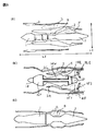
- FIG. 2A shows the blades of the front row of blades arranged in the circumferential direction of the rotating shaft and the rear rows arranged in the circumferential direction of the rotating shaft, which constitute the moving blade or stationary blade of the axial compressor.
- An example of a simplified diagram showing the blades of the blade row of (W1) located in the front row is a blade in a row of moving blades or stationary blades arranged in the circumferential direction of the rotating shaft
- (W2) located in the rear row is a blade in a row of moving blades or stationary blades arranged in the circumferential direction of the rotating shaft
- (LX) is an axial reference line that is a line parallel to the rotation axis (hereinafter, in this specification, a line parallel to the rotation axis is referred to as an “axial reference line” or “a line parallel to the rotation axis”.
- (Sa) is the angle formed by the chord line (ch) and the axial reference line (LX), the stagger angle
- the angle of the stagger angle of the front row of blades (W1) and the angle of the stagger angle of the rear row of blades (W2) are "opposite direction” or “direction close to the opposite direction”. It is configured.
- Non-Patent Document 39 In the example of the same or similar positional relationship between the blades of the front row of blades and the blades of the rear row of blades in FIG.
- FIG. 2B shows a conventional general axial compressor of a front row and a rear row of moving blades configured in a rotor, or a front row and a rear row of stationary blades formed in a stator. An example of a simplified diagram showing the positional relationship is shown.
- the stagger angle of the blade (W1) of the front row of blades arranged in the circumferential direction of the rotating shaft and the rear row arranged in the circumferential direction of the rotating shaft is configured to be "parallel direction" or "direction close to the parallel direction".
- the front stage fixed to the rotor of a conventional general axial compressor is used.
- a dotted line (xx ′) is an axial reference line (LX) that is a line parallel to the rotation axis of a moving blade that is positioned concentrically and rotates in the front-rear direction of the rotation axis.
- the direction of the front row blades (w) and the rear row blades (w) of the axial compressor that is, the front and rear direction of the rotating shaft and the front blade edge (Le) of the rotor blade,
- the direction of Te is the direction of the blades in the same direction as the direction of gas flow
- the direction of the blades in the front row of the compressor and the direction of the blades in the rear row are opposite directions, In the case of the example of FIG.
- FIG. 2D shows an example of a simplified diagram for explaining the axial flow compressor.
- FIG. 2E shows an example of a simplified diagram of the air flow from the moving blades and the stationary blades.
- LX is an axial reference line
- the front rotor blade (w1) and the rear rotor blade (w2) fixed to the same rotor (R) have the rotor (R) in the direction of arrow 1.
- the gas is exhausted from the suction port toward the gas discharge port, and a flow is created in a direction parallel to the rotation axis of the arrow 4.
- a conventional general axial compressor in which a plurality of rows of moving blades (W) fixed to the same rotor are arranged in multiple stages with a stationary blade (sw) interposed therebetween forms a stage.
- 3A shows an example of a simplified schematic diagram of a conventional turbofan engine (explained with reference to pages 155 to 175 of Non-Patent Document 39 and page 87 of Non-Patent Document 42).
- a rotor of an axial flow compressor comprising a rotor and a turbine for fixing a rotating rotor blade for a fan
- (2) is a casing that surrounds and exhausts the rotor (1) of the axial flow compressor in a cylindrical shape
- (3) is a bypass space constituted by a low-temperature bypass flow nozzle that does not pass through the high-pressure compressor but passes through the outer peripheral side
- (3 ′) is constituted by a high-temperature core flow nozzle that passes through the high-pressure compressor on the inner peripheral side.
- (4) is a combustor (including a combustion chamber) that burns fuel for rotating the turbine, (LX) is “a line parallel to the rotation axis”, and (LY) is “parallel to the rotation axis”.
- the compressor, medium compressor and high compressor are collectively used as a compressor.
- the combustor is located between the compressor and the turbine, and is composed of an outer cylinder called a casing and an inner cylinder called a liner, and there are a can type, an annular can type, and an annular type (non-patent document).
- fuel injection Machine (explained with reference to page 51 of Non-Patent Document 38, etc.), in order to exceed the heat resistance temperature of the liner heated by combustion, cooling air is poured into the liner wall from the louvers and slits to protect the liner It has a structure to do.
- FIG. 3 shows an example of a simplified diagram of a conventional turbofan engine
- (1f) is a nose cone
- (1r) is a tail cone
- the air from the low-pressure compressor (1Lr) is converted into a bypass flow from the space (3) created by the outer casing (2L) and the high-pressure side casing (2H) serving as a bypass flow nozzle, and the high-pressure compressor (1Hr).
- the high pressure compressor (1Hr) is connected to the high pressure turbine (1Ht) via a shaft
- the low pressure compressor (1Lr) is connected to the low pressure turbine (1Lt) via a shaft.
- Non-Patent Document 40 The turbine that drives the compressor by converting the high-temperature and high-pressure gas energy from the combustor into mechanical energy is the turbine, and the axial turbine is a stationary blade (nozzle) and moving blade (blade). ) Are alternately arranged (pages 46 to 49 of non-patent document 38, pages 106 to 108 and pages 118 to 120 of non-patent document 40, and non-patent document 39). Pp. 386 to 455). In FIG.
- (af) is a reburning device
- (af1) is a fuel injection strut
- (af2) is a flame holder, which mixes the combustion gas from the turbine and the air from the fan, It is an apparatus that reheats exhaust gas to obtain thrust, and consists of an outer cylinder and an inner cylinder, and is provided with louvers and slits for cooling.
- Non-Patent Document 40 page 100, pages 122-132, pages 120, 121, etc.
- a thrust deflection nozzle is provided on the exhaust side at the rear of the reheat device.
- the exhaust nozzle can be increased or decreased by a variable mechanism, and the thrust can be deflected from the axial direction to the direction perpendicular to the axis.
- FIG. 3C shows an example of a simplified diagram of a conventional turbojet engine (explained with reference to page 86 of Non-Patent Document 42). Air from the compressor is sent to the combustor as it is and the turbine is turned. A jet engine of the form. Examples of the jet engine include a turboprop engine and a turboshaft engine (described with reference to pages 170 to 173 of Non-Patent Document 41).
- the conventional rotating shaft is coaxially or nearly coaxially arranged in the front-rear direction, and the rotor blade rows and stationary blade rows are alternately arranged, and the rotor blades constituting the rotating shaft rotate to rotate the air from the front to the rear.
- the axial flow compressor of the thrust generating device that was compressed and sent in the direction In a rotor in which a row of blades of a moving blade inclined in a certain direction is installed, the direction opposite to the inclination of the blade (w) with respect to the axial reference line in front of or behind the row of blades of the rotor (conventional shaft) It was impossible to construct a row of blades arranged in the vane side of the stationary blade relative to the axial reference line of the flow compressor.
- the conventional rotating shaft is coaxially or nearly coaxially arranged in the front-rear direction, and the rotor blade rows and stationary blade rows are alternately arranged, and the rotor blades constituting the rotating shaft rotate to rotate the air from the front to the rear.
- the axial flow compressor of the thrust generating device that was compressed and sent in the direction
- an axial flow compressor that is only on the outer peripheral side of the blade of the moving blade
- the rotor blades that are stacked in multiple stages alternately in the front-rear direction of the rotating shaft are separated separately, and with a simple structure and compactly rotated opposite to the forward rotating rotor blades. It was difficult to install a moving blade.
- the present invention is to solve the problems of the conventional axial compressor as described above,
- the blades in the previous stage and the next subsequent stage can install blades that are inclined in the direction along the direction of the wind that is sent,
- the rotating shaft of the rotor blade rotating in the reverse direction to the forward rotation is a rotating body for forward rotation in which blades for a plurality of blades are fixed, and a rotating body for reverse rotation in which blades for a plurality of rows of blades are fixed,
- the object is to be able to configure arbitrarily arbitrarily.
- the solution for the axial flow type thrust generating device of the present invention comprises a moving blade having a row in which a plurality of blades with twists and angles are arranged, and a rotating rotating body.
- the center of rotation of the body is concentric or nearly concentric in the front-rear direction of the rotating shaft of the rotor blade, and is alternately combined to form multiple layers, and by rotating in each rotating direction, gas is supplied from the front to the rear of the rotating shaft.
- an axial flow compressor comprising a casing for rotating and supporting a rotor for power, a plurality of blades arranged in a row on the inner circumference of the outer ring for power or the outer rotor for power
- a moving blade is configured by radially arranging and fixing in the inner direction of the ring or outer rotor for power, and a bearing structural unit for rotating and supporting the moving blade is configured on the outer peripheral side or inner peripheral side of the moving blade.
- the rotating body constituting the rotor power member on the outer peripheral side of the row of blades of the moving blades, and the plurality of blades arranged in a row on the outer circumference of the power disk or power inner rotor
- a rotating blade is configured by arranging and fixing radially outward of the disk for power or the inner rotor for power, and a bearing structural portion for rotating and supporting the moving blade is provided on the inner peripheral side or outer peripheral side of the moving blade.
- Configured, dynamic Rotating body constituting a power element for the rotor in the inner row of blades of, and characterized in that a configuration.
- the axial flow type thrust generating device includes a rotating member moving in each row of moving blades composed of a plurality of blades constituting the moving blade of the rotor for the axial flow compressor described in 0049 above.
- a rotor for an axial flow compressor comprising a shroud or a connection ring for reinforcing connection between adjacent blades in a row of blades on a rotating circle located at the same or substantially the same distance from the rotation center of the blade, It is characterized by comprising.
- the axial flow type thrust generating device of the present invention is the casing described in 0049 above, the outer peripheral side of the row of blades of the rotor blade in the rotor having the rotor outer ring or the rotor outer rotor described above.
- a structure part for the inner side of the casing which is composed of a structure part for bearings for rotating and supporting the rotating blades and a structure part for bearings for rotating and supporting the rotating body.
- the axial flow type thrust generating device of the present invention is the casing described in the above 0049, on the inner peripheral side of a row of blades of a rotor blade in a rotor having an outer ring for a rotor or an outer rotor for a rotor.
- the structure of the bearing is a structure for the rotation of the bearing for support and the structure of the structure for the bearing for support.
- the structure portion of the casing is arranged and fixed radially on the circumference in the casing side direction.
- the axial flow type thrust generating device according to the present invention is the rotor or the casing for the axial flow compressor described in the above-mentioned 0049 to 0052.
- the above-described rotor in the rotor for an axial compressor, and the stator structure corresponding to the above-described rotor, and the casing structure portion in the vicinity of the above-described rotor are configured. It is characterized by that.
- the axial flow type thrust generating device according to the present invention includes a rotor for an axial flow compressor described in the above 0049 to 0052 and an outer ring for power of the rotor for an axial flow compressor in the structural part of the casing.
- a rotor for a rotor configured with gear teeth for power transmission on the circumference of the outer rotor for power and a gear device for transmitting power to the rotor for rotor described above are configured.
- the casing structure portion in the vicinity of the power outer ring or the power outer rotor is configured as described above.
- the axial flow type thrust generating device of the present invention comprises a rotor or a casing of an axial flow compressor described in the above 0049 to 0054, wherein a magnet or a magnetic body is configured as a component of a rotating body.
- the axial flow type thrust generating device of the present invention is the rotor for the axial flow compressor described in the above 0049, and the rotor constituting the rotor power member on the inner peripheral side of the row of blades of the moving blades, Alternatively, a gas turbine turbine for connection or integral configuration with a rotating body constituting the rotor power member on the outer peripheral side of the row of blades of the moving blade is configured.
- the action of the above 0049 is a moving blade having a row in which a plurality of blades with twists and angles are arranged, and a rotating body rotating in either one of a rotating rotating body and a rotating counterclockwise rotation is ordered.
- the rotating body for rotation, the other rotating body as a rotating body for reverse rotation, and the rotational center of the rotating body for forward rotation and the rotating body for reverse rotation described above are concentric or substantially concentric in the longitudinal direction of the rotating shaft of the moving blade.
- a casing for rotating and supporting a rotor for an axial compressor In the axial flow compressor, the plurality of blades arranged in a row on the inner circumference of the outer ring for power or the outer rotor for power are arranged radially inward of the outer ring for power or the outer rotor for power.
- the structure for bearings is used for rotating and supporting the moving blade on the outer peripheral side or inner peripheral side of the moving blade.
- a rotating body constituting a rotor power member and a plurality of blades arranged in a row on the outer circumference of the power disk or power inner rotor radially toward the outer side of the power disk or power inner rotor
- the moving blades located in the rear row next to the front row of moving blades have blades inclined at an angle according to the direction of the wind sent from the front row of moving blades. It is possible to install in multiple stages a rotating body that rotates by the power from the rotating shaft side of the blade of the moving blade and a rotating blade that rotates in the reverse direction by the power from the outer peripheral side of the blade of the moving blade. It is.
- the action of the above 0050 is the same as the rotation center of the rotor blades of the rotating body in each row of the rotor blades composed of a plurality of blades constituting the rotor blades of the rotor for the axial flow compressor described in the above 0049 or A rotor for an axial flow compressor having a shroud or a connection ring for reinforcing connection between adjacent blades in a row of blades on a rotating circle located at substantially the same distance. Therefore, it is possible to constitute a reinforcing support on the blades of the moving blades in the rotor for the rotor.
- the action of the above 0051 is the rotation and support of the moving blade on the outer peripheral side of the row of blades of the moving blade in the rotor having the rotor outer ring or the rotor outer rotor described above in the casing described in the above 0049.
- the inner structure of the casing is composed of the inner structure of the casing and the structure of the bearing for rotating and supporting the rotating body and the structure for the bearing. It is possible to fix so that the rotary body which comprises a moving blade can rotate in the surface vicinity of the surface of this or a casing.
- the operation of the above 0052 is for rotating and supporting the moving blades on the inner peripheral side of the blade row of the moving blades in the rotor having the outer ring for the rotor or the outer rotor for the rotor in the casing described in the above 0049.
- the bearing for rotating and supporting the rotor blade on the inner peripheral side of the blade array of the rotor blade A structure portion for rotating and supporting the rotating body with the structure portion, and a plurality of stationary blades or struts radially from the structure portion for the bearing that is not on the rotating body side described above in a radial direction in the casing side.
- the rotating body constituting the moving blade is fixed so as to be rotatable at the center side of the casing, that is, the rotation center side of the moving blade.
- the function of the above 0053 is the above-described rotor for an axial compressor and the structural part of the casing described in the above-mentioned 0049 to 0052. Since the rotor body in the rotor for an axial compressor and the conductor for the stator corresponding to the rotor described above are configured, the casing structure portion near the rotor is configured.
- the function of the above 0054 is the structure of the rotor for an axial compressor and the casing of the casing described in the above 0049 to 0052, and the outer ring for power of the rotor for an axial compressor or the circle of the outer rotor for power described above.
- the rotor for a rotor configured with gear teeth for power transmission on the circumference and the gear device for transmitting power to the rotor for the rotor described above are configured.
- the axial flow type thrust generating device has an outer ring for a rotor having gear teeth, and its In the vicinity of the outer periphery of the outer ring for the rotor, it is possible to install a power mechanism comprising a power transmission gear for the outer ring for the rotor.
- the operation of the above 0055 is the rotor of the axial flow compressor described in the above 0049 to the above 0054, and the structure part of the casing. Because the structure of the casing structure near the rotating body described above, the conductor is configured for power, power generation, or braking by electrical resistance corresponding to the magnet of the rotating body or similar to the magnet.
- blades positioned in the rear row next to the front row of moving blades can be installed with blades inclined at an angle in accordance with the direction of the wind sent from the front row of moving blades. Because it is possible to install the rotating body rotating by the power from the rotating shaft side of the blade of the moving blade and the moving blade rotating in the opposite direction by the power from the outer peripheral side of the blade of the moving blade, When installing an axial flow compressor with multiple stages of rotating blades rotating in the opposite direction behind the rotating blades rotating in one direction, multiple rows of moving blades rotating in the same direction can be efficiently It has the effect that it can be rotated by a rotating body.
- the thrust generating apparatus can form a reinforcing support on the blades of the rotor blades in the rotor for the rotor, so that the rotation of the blades for the rotor blades in the rotor is rotated.
- the thrust generating device according to the present invention rotates in one direction because the rotor constituting the moving blade can be fixed so as to be rotatable on the inner surface of the casing or in the vicinity of the inner surface of the casing.
- the thrust generating device can fix the rotating body constituting the moving blade to be rotatable at the center side of the casing, that is, the rotation center side of the moving blade.
- the moving blades that rotate in the opposite direction behind the blades are installed in multiple stages, there is an effect that the support portion for rotating the moving blades can be concentrated on the rotation center side.
- a rotor having a magnet or a magnetic body and a stator mechanism in a casing near the outer periphery of the rotor may be installed on the outer peripheral side of the blade of the rotor blade.
- the thrust generating device of the present invention is an axial-flow type thrust generating device comprising: a rotor outer ring having gear teeth; and a rotor outer ring in the vicinity of the outer periphery of the rotor outer ring. Since it is possible to install a power mechanism composed of a power transmission gear, even in the case of a normal jet engine compressor, the power of the turbine can be It has the effect that a moving blade can be rotated using.
- a generator or a device that reduces the rotational speed of the axial thrust generator by electric power can be installed on the rotating body and casing of the axial thrust generator. Therefore, there is an effect that power can be generated by an axial compressor for power, or the rotational speed of the compressor can be adjusted using electric power.
- the axial flow type thrust generating device of the present invention can be installed with a rotor for an axial flow compressor having a rotating body that rotates with the force of a turbine. This has the effect of being able to design a thrust generating device of the formula.
- FIG. 1 is a simplified example of a simple description of hydrodynamics.
- FIG. 2 is an example of a simplified diagram for explaining an axial compressor.
- FIG. 3 is a simplified example of a conventional jet engine.
- FIG. 4 is a shaft of claim 1 of the present invention.
- FIG. 5 is an example of a simplified diagram of a compressor blade that can be used in the present invention.
- FIG. 6 is a simplified diagram for explaining a blade of claim 6 of the present invention.
- FIG. 7 is an example of a simplified diagram of a compressor blade of claims 1 and 5 of the present invention.
- FIG. 8 is an example of a simplified diagram of a compressor blade of claim 1 of the present invention.
- FIG. 9 is a diagram of a compressor blade of the present invention.
- FIG. 1 is a simplified example of a simple description of hydrodynamics.
- FIG. 2 is an example of a simplified diagram for explaining an axial compressor.
- FIG. 3 is a simplified example of a conventional jet engine.
- FIG. 10 is a simplified example of a casing structure that can be used in the present invention.
- FIG. 11 is a simplified example of a hollow structure that can be used in the present invention.
- FIG. 14 is used in the present invention.
- a simple example of the structure of a possible box-shaped thrust generator 5 is an example of a simplified diagram of a hydraulic device that can be used in the present invention.
- FIG. 16 is an example of a simplified diagram of a deflecting plate that can be used in a thrust generating device.
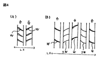
- FIG. 4 shows an example of a simplified diagram of an axial flow compressor portion for explaining “axial flow compressor” according to claim 1 of the present invention
- (LX) is the “front-rear direction of the rotating shaft of the moving blade”
- FIG. 4A is the “rotating body rotating right and rotating body rotating left” according to claim 1.
- One of these is the “rotary body for forward rotation” and the other is the “rotary body for reverse rotation”
- the blades (W) of the front and rear blades with twists and angles are indicated by arrows.
- FIG. 4B shows an example of a configuration in which a stationary blade (sW) is interposed between a front row and a rear row of moving blades (W), and the flow from the moving blade (page 240 of Non-Patent Document 39).
- sW stationary blade
- W moving blade
- rectification is performed along the flow, and the moving blade (W) in the next row of the stationary blade (sW) is inclined in the same direction (parallel direction) with respect to the front and rear axes as the previous stationary blade (sW). Therefore, it becomes possible to perform rectification along the flow by the stationary blades and acceleration of the flow by the moving blades (the inclination angles themselves may be the same or different, and the manufacturer can arbitrarily To do).
- a row of inlet guide vanes is provided in front of the front row of moving blades of the present invention, or the moving blades are arranged according to the rotational speed of the moving blades.
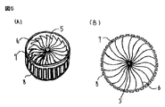
- FIG. 5 shows an example of a simplified diagram of an electric rotor blade that can be used in the present invention.
- FIG. 5A is a view of the air suction side of the electric rotor blade as seen from an oblique direction.
- 5 (B) is a view of FIG. 5 (A) as seen from the upper front, and
- FIG. 5 (5) is a rotating shaft or bearing for rotating the moving blade (if it is a protrusion, it becomes a shaft and has a hole shape).
- (6) is a blade of a moving blade for sending air backward
- (7) is a “power outer ring or power outer rotor” according to claim 1 of the present invention.
- the outer ring (7) for a rotor according to claim 5 of the present invention wherein the outer ring (7) has a magnet (8) of a "rotor power member" on the outer periphery of the ring and the blade (6) is fixed on the inner periphery of the ring.
- the “stator for the rotor described above” according to claim 5 of the present invention is installed in a casing or a fan casing and rotated.
- (6) is the “twisted or angled blade” according to claim 1
- (5) is the “inner circumferential side of the blade” according to claim 1.
- the outer ring for power is composed of a “structure part for bearings for rotating and supporting the moving blades”.
- FIG. 5 shows a type utilizing the operating principle of an in-wheel motor for an electric vehicle (see pages 54 to 57 of Non-Patent Document 17, etc.).
- FIG. 6A shows an example of a simplified diagram for explaining the moving blade of claim 6 of the present invention, and FIG. 6A shows a “power outer ring or power similar to claim 6 that rotates in a certain direction.
- (10) is a "power outer ring or power outer rotor” that rotates in the reverse direction to (9), and (10 ') is “a gear tooth for power transmission”. 10) rotates around a dotted line (X) which is the rotation center of the rotation shaft, and (9) and (10) are the counter-rotating “rows of blades” according to claim 1, respectively. If the rotating body constituting the rotor power member is installed on the inner peripheral side of the rotor, the moving blade of claim 6 can be obtained.
- the gear (11) is connected to the casing or the engine structure in the vicinity of the casing so as to be rotatable,
- the gear (11) rotates about the rotating shaft (12) that rotates about the dotted line (Y) of “the radial line of the axial compressor”,
- Gear (11) is connected to (9 ') and (10') so that the gear teeth mesh,
- the gear (11) rotates (9 ′) and (10 ′) in the opposite directions in the direction of the arrow shown in the simplified view of FIG. .
- FIG. 6C shows an example of a simplified diagram of the combination of FIG. 6A and FIG. 6C.
- the rotors 9 on both sides connected to the turbine shaft rotate to rotate the gear (11 )
- the left and right gears (13) are connected via a transmission (14 ′′)
- the transmission (14 ′′) is usually
- the accessory gearbox see page 165 and page 179 of Non-Patent Document 41
- it is provided outside the moving blade.
- a portion where a reduction gear, a gear, or the like for changing the rotating speed of the moving blade is provided on the rotating shaft side of the moving blade (page 36 of non-patent document 41 and page 174 of non-patent document 39).
- the type of the blade is not limited as long as it meets the conditions of the present invention, such as being installed on the outer circumferential side of the moving blade.
- (13) and (14) make it possible to disperse the load of the moving blade connected to the turbine on both the rotor side and the outer peripheral side of the ring.
- the power transmission device is described in Non-Patent Documents 14, 15, 16, 17, 18, 19, etc., and the type of the power transmission device is not limited as long as the claims of the present invention function safely.
- the transmission (14 ′′) includes a rotating shaft (14 ′′) to a power transmission device of another rotor or an axial compressor, and transmits power to a portion requiring other power.
- FIG. 7 shows a simplified diagram of an example of a model showing the positional relationship of the axial compressor according to claim 1 of the present invention, and bearings, cages and their supporting structures used in the claims of the present invention are:
- bearings, cages and their supporting structures used in the claims of the present invention are:
- There are various types such as rolling bearings, plain bearings and bearings, structures and materials similar to those used in jet engines, and those using the bearing for alternator of Non-Patent Document 6, etc.
- Those types are not limited as long as they satisfy the requirements. (See pages 54 and 55 of Non-Patent Document 38, Non-Patent Documents 6 and 7)
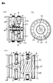
- FIG. 7A is a schematic cross-sectional view of an electric compressor rotation power mechanism for compressing air and sending it from the front to the rear, and FIG. 7A is a claim.
- An axial flow compressor in which “the rotation centers of the forward rotation rotor and the reverse rotation rotor are concentric or substantially concentric in the front-rear direction of the rotating shaft of the rotor blade, and are alternately combined to form multiple layers” It is a moving blade.
- the rotor of the power mechanism for rotation in the axial compressor of FIG. 7A includes “power disk or power inner rotor” (15) and “power outer ring or power outer rotor” (26).
- a magnet (21) is installed in (15) as a rotor for a motor, and a conductor (electric wire) is provided as a stator for the motor.
- Installed coil part (20) In the cylindrical “outer ring for power or outer rotor for power” (26), a magnet (29) is installed in (26) as a rotor for a motor, and a conductor is used for a function as a stator for a motor.
- the coil part (28) having the (electric wire) was installed in the “structure inside the casing” (23), This is a power mechanism for rotating the compressor.
- (A) of claim 7 The rotor blades rotating in one direction are arranged in a row on the outer circumference of the “power disc or power inner rotor” (15) according to claim 1, “arrayed and fixed radially outward”. It is a “rotary body” in which three rows of blades (16) for a plurality of blades are arranged, The rotor blades rotating in the other opposite direction form a row on the inner circumference of the “power outer ring or power outer rotor” (26) according to claim 1, arranged radially in an inward direction. And “fixed” is a “rotary body” in which two rows of blades (27) for moving blades are arranged in two rows.
- FIG. 7A shows the force of the magnet rotor (21) installed on the inner side of the “power disc or power inner rotor” (15) and the conductive coil (20) installed on the rotating shaft (22).
- the motor outer ring or power outer rotor (26) is installed on the outer side of the magnet rotor (29) and the casing (23) having a hole structure on the outer periphery of the electric rotor blade.
- FIG. 7B is a simplified view of the moving blade fixing support portion installed in the air introduction passage, as viewed from the front in the vertical direction of FIG. 5.
- a plurality of stationary blades or struts are radially arranged on the circumference in the casing side direction from the bearing structural portion that is not on the rotating body side.
- the stationary vane-shaped legs (25) and (24), which are the “structure portion of the fixed casing”, are circumferential structures that fix the legs (25), It can be installed in various places such as a combination of bearings used in the present invention, and a constituent position of a rotor outer ring (rotor), a rotor disk (rotor), a bearing, and the like. As long as the conditions are satisfied, there are no limitations on the fixing method, shape, structure, and material of the rotor and the rotatable rotor in the casing.
- (C) of FIG. 7 is a model diagram simply showing the positional relationship between the ring-shaped inner side bearing blade fixing portion (15) and the shaft side bearing fixing portion (22).
- FIG. 7 is a simplified diagram of “power disk or power inner rotor” (15), which is a blade fixing portion of the inner-side moving blade, based on the compression portion of the jet engine (the jet engine is a blade Although the portion located at (27) is a simplified diagram of stationary blades), the types thereof are not limited as long as they satisfy the conditions of the present invention, such as the shape, structure, and material of blades and rotors of moving blades.
- FIG. 7E shows an example of a simplified view of the moving blade portion of FIG. 7F viewed from a direction parallel to the rotation axis.
- a cylindrical “power outer ring or power outer rotor” (26) The blades (27) of a plurality of moving blades are radially arranged inside and fixed, and the rotating shaft ring is arranged on the rotating shaft side (the inner peripheral side of the moving blade) of the blades (27) of the plurality of moving blades.
- a ring (26 ′) that serves as a bearing for rotating the rotor blade for connection with (SWR) is fixed.
- FIG. 7 (F) is a simplified view of claim 1 of the present invention of the appearance of the blade fixing portion (15) of the moving blade and the stationary blade as seen from the direction perpendicular to the rotation axis of FIG. 7 (E).
- An example of The rotating shaft ring (SWR) is made up of the stationary blades (SW) by the stationary blades (SW) fixedly installed inside the casing (23) and the plurality of radially arranged stationary blades (SW). ) And the rotating shaft side of the rotor blade (27) can be rotated on the outer peripheral side of the bearing ring (SWR) for supporting the rotor blade.
- the rotor disk (rotor) is connected to the rotating shaft of the rotating shaft (SWR) and the rotating blade (16) rotating in the reverse direction to the rotating blade (27) is fixed on the rotating shaft side of the rotating shaft ring (SWR).
- the thrust generating device having the shape shown in FIG. 7 (F) can be installed on the rotating shaft side because a moving blade fixed by a stationary blade can be installed from the rotating shaft side of the axial compressor.
- the rotor can transmit power of a rotating blade rotating in the opposite direction without receiving mechanical friction of the moving blade.
- FIG. 8 is a simplified diagram of an example of a model showing the positional relationship between the “casing” (23) according to claim 4 of the present invention and the “compressor in which a plurality of moving blades are layered”. While compressing the air by having the rotation center coaxially or substantially coaxial in the direction and the blades for right rotation and the blades for left rotation (16) and (27) alternately rotate in reverse and combined in multiple stages It exhausts from the front to the rear of the casing.
- FIG. 8A is a simplified cross-sectional view of the electric rotor blade from the side.
- FIG. 7A shows that the rotor outer ring (26) is fixed by the casing (23) and rotates.
- the rotor outer ring (32) is fixed by a ring-shaped bearing (31) so as to be rotatable by the inner rotor (15).
- the power outer ring (32) in FIG. 8 is fixed to be rotatable by the bearing structure (31) through the inner rotor (15) and the bearing (19).
- 8A is rotated by the force of the magnet rotor (21) installed inside the rotating rotor (15) and the conductive coil (20) installed on the rotating shaft (22).
- FIG. 8B is a simplified view of the cross section of the dotted line (xx ′) of FIG. 8A viewed from the front, and shows a ring-shaped inner rotor bearing (15) and a shaft-side bearing.
- FIG. 8C is a simplified view of the external appearance of the thrust generator of FIG. 4 in which the blade fixing portion (33) of the moving blade on the inner side has a rotor connected to the turbine.
- An outer rotor (31) is fixed to a stationary blade (34) having a rotation shaft so as to be rotatable in the front-rear direction, and an outer rotor (33) rotating in a reverse direction to (31) is connected to a turbine of a jet engine.
- the shape is not limited as long as it satisfies the conditions of the present invention, such as the shape, structure, and material of blades and rotors of a moving blade.
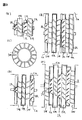
- FIG. 9 shows an example of a simplified diagram showing the vicinity of a moving blade according to claim 1 of the present invention, (IR) is defined in claim 1 as “a row outside the power disk or power inner rotor ... a radially arranged and fixed configuration of the moving blades”.
- FIG. 9A shows a compressor for a compressor, in which a pair of a rotor outer ring that rotates in a certain direction and a rotor outer ring that rotates in a reverse direction are layered in pairs.
- B in FIG.
- FIG. 9 shows a rotor blade (IRf) that is located on the front side of a plurality of rotor outer rings (OR) that rotate in the reverse rotation direction, and a rear side (IRf).
- a single axial compressor is shown in which a moving blade (OR) and a stationary blade (SW) are sandwiched between moving blades (IRr), which are positioned (IR), rotating in a certain direction.
- FIG. 9C shows an example of a simplified view of a stationary blade as seen from the front.
- the ring structure on the inside keeps the support and atmospheric pressure in the vicinity of the rotor of the moving blade.
- There are no limitations on the type such as a mechanism, shape or structure such as a combination of a shaft or a bearing structure using any bearing.
- FIG. 9D shows a single rotor outer ring (OR) that rotates reversely to two stationary blades (SW) between one blade (IR).
- FIG. 9E shows a rotor outer ring (OR) having two independent counter-rotating motions with respect to (IR) between one rotor blade (IR) and rotor blades (IR) and (OR). ) Are provided with stationary vanes (SW) on both front and rear sides.
- the casing (Ca) has a space for ventilation from the vicinity of the intake port to the vicinity of the exhaust port having almost the same size, but actually the space for ventilation is partially squeezed.
- the shape and the type of structure are not limited.
- the type of the outer ring is not limited, for example, the outer ring for the rotor having a power source on the center side is kept at a constant rotational speed, and a plurality of outer rings for the outer peripheral side having various rotational speeds are provided.
- the number of blades in (IR) and (OR), the number of rotating rotor blades, the pattern of their combination, the shape, structure, and material constituting them are various, so long as they satisfy the conditions of the present invention. Those types are not limited.
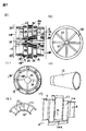
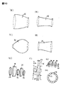
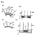
- (A), (B), (C), and (D) in FIG. 10 are casings that allow air to flow to the outer peripheral side of the moving blade that flows gas to the inner peripheral side of the moving blade that can be used in the present invention.
- FIG. 4B is a simplified diagram of a casing-shaped or outer rotor-shaped air passage surface that is gradually narrowed from the inlet side to the exhaust port side
- FIG. 4D is a simplified view of an inner rotor-shaped air passage surface
- FIG. 4D is a simplified view of an inner rotor-shaped air passage surface that is gradually widened between the intake side and the exhaust port side and the exhaust port side is widened.
- FIG. 10 is narrowed in the shape in which the intermediate portion is narrowed when assembling the casing or outer rotor in which the exhaust port side in (35) is gently narrowed and the inner rotor in (36).
- it shows what is assembled by sandwiching from both sides of the part, it may be of a shape that is divided into upper and lower parts and fixed by sandwiching the moving blades from above and below as in a normal casing (Non-Patent Document 40).
- FIG. 10 (F) shows what is assembled by sandwiching the inner rotor (15) from both sides of the bearing of the outer rotor (31).
- FIG. 10G shows an example in which the rotor member (38) is connected and fixed with bolts (37 and 37 ′) with threads.
- FIG. 10 (H) shows an example of a simplified view of the rotor portion using FIG. 10 (G) as seen from the front, and FIG.
- Each member may be produced by a 3D printer (see Non-Patent Document 27 and Non-Patent Document 26), a machine tool (see Non-Patent Document 28), a mold, or the like (page 21 of Non-Patent Document 26). Etc.)
- the type is not limited.
- the types of production using a 3D printer are metal hot melt lamination (such as page 53 of Non-Patent Document 27), multi-layer lamination solidification (such as page 53 of Non-Patent Document 27), and binders, which are lamination production methods.
- Spray lamination such as pages 67 and 71 of non-patent document 27
- 3D sand casting such as page 70 of non-patent document 27
- directional energy deposition such as page 77 of non-patent document 27
- melt deposition such as page 104 of Non-Patent Document 26
- laser direct lamination such as page 104 of Non-Patent Document 26
- electron beam melting such as page 77 of Non-Patent Document 27
- a manufacturing method such as a powder sintering method (such as page 92 of Non-Patent Document 26) or thin film lamination (such as page 79 of Non-Patent Document 27)
- the shape or structure is complicated, or the interior is hollow. It becomes possible to make things like a grid.
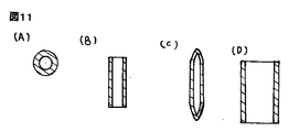
- FIG. 11 shows an example of a simplified diagram of a structural portion that can be used in the present invention.
- FIG. 11A is a rotating shaft with a hollow inside
- FIG. 11C is a cross-sectional view of A) viewed from the side.
- FIG. 11C is a stationary vane that can be used in the present invention
- FIG. 11D is a side view of FIG.
- FIG. 12 shows an example of a simplified diagram of the structural parts that can be used in the present invention.
- FIG. 12A shows a simplified diagram in which the rotor constituting magnet and the conductor of claim 5 are configured in FIG. 7F, and the stationary blade (SW) is fixed to the casing (23).
- the magnet (21) installed on the outer peripheral side of the rotating body (15) located on the rotation center side, the conductor (20) being installed on the rotation center side to constitute the "casing structure part" according to claim 5, It is the simple figure which showed what rotates with a conductor (20).
- FIG. 12B shows a simplified view of FIG. 12A viewed from the side, and the moving blade “power outer ring” (26) of FIG. 7E between the front and rear (SW). It has a space where can be installed.
- C of FIG. 12 shows a simplified view of a “casing structure portion” in which the stationary blade (SW) is fixed to the casing (23) and the conductor (20) is installed toward the outer peripheral side on the rotation center side. A rotor blade can be installed and rotated between the outer peripheral side (23) and the inner peripheral side (20).
- D) in FIG. 12 shows that a plurality of conductors (C) in FIG.
- 12 passing through the inside of the stationary blade (SW) are formed in the front-rear direction of the rotating shaft, and a row of blades is formed between the stationary blades (SW).
- 12 is a rotor for an axial flow compressor having a shape in which a rotor blade (15) having a bearing portion configured to constitute a power member of a rotor on the circumferential side and rotatably supported on the outer circumferential side of a row of blades is installed.
- (D) is different from the moving blade of the present invention, it can be used as a part of the moving blade of the present invention.
- FIG. 13A shows a state in which one row of blades is formed on the inner side of the rotor (26) constituting the rotor power member on the outer peripheral side of the blade row of the rotor blades of claim 1.
- FIG. 5 is a simplified diagram showing a blade array part and two blade rows in the front-rear direction that are connected to a component supporting a rotor blade made of a stationary blade on a rotating body of (15 ′).
- FIG. 13C illustrates the rotor blade (26) of claim 1 and the stator (SW) of the stationary blade for fixing the rotor blade which is divided into the upper and lower portions in the same manner as the stator of a normal axial compressor.
- (15) is a structure of a bearing structure for rotating and supporting the moving blade on the outer peripheral side of the moving blade (15) by (SW), and (15) is a row of blades (16) of the moving blade.
- the power member for the rotor is configured on the inner peripheral side of the rotor.
- FIG. 13D is a simplified diagram showing the member (38) and the bolt (37 ′) for fixing the members together.
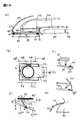
- FIG. 14 shows an example of a simplified diagram of the structure of a box-shaped thrust generating device that can be used in the present invention and has a compressor inside
- FIG. 14A can be used in the present invention.
- FIG. 14B is a cross-sectional view of a possible box-shaped structure for thrust generation from the side
- FIG. 14B is a cross-sectional view of FIG. 14A viewed from above
- FIG. And (D) is a cross-sectional view of the rear structure of the box-shaped structure
- FIG. 14 (E) is a cross-sectional view of the lower vicinity structure of the front portion of the box-shaped structure
- FIG. It is sectional drawing of the upper part vicinity structure of the front part in a box-shaped structure.
- FIG. 14A is a rotor blade having a rotor structure on the outer peripheral surface side
- FIG. 14A is a rotor blade of FIG. 5 that is connected to a rotating shaft 39 and rotates.
- the stator coil (41) provided inside (51) is rotated by the principle of a motor, and has a radial blade structure similar to a stationary blade of a jet engine via a rotating shaft (39) (51 ) Is connected to the leg (42) fixed to.
- (45) and (51) constituted by a nacelle having a plurality of casings connected in the front-rear direction of the air flow inside the casing, and a ring-shaped rotating shaft (44) having a hollow center disposed in one casing And the above-mentioned ring guide bearing installed in the other casing and connected through the center side of the rotating shaft by the connecting portion (43) of the connecting ring having a hollow center, and rotated clockwise and counterclockwise And a casing structure having a ring-shaped rotating shaft mechanism in which a cavity is formed for ventilation.
- (47) is an opening / closing lid that can cover part or all of the opening, and is a lid that opens and closes by vertical movement, and is a bypass that exhausts air from (42), (46) It is an axial flow compressor.
- 14 (B) is a hole penetrating vertically inside the nacelle formed by (43) and (44), and (48 ') is the air passing through the compressor (46) to the outside.
- (45) is a simplified view of the vicinity of a box-shaped casing that can be rotated by a robot arm (52) connected to (51) by a rotating shaft. (C) and (D) in FIG.
- FIG. 14 shows that the lid of (47 ′) and (47 ′′) rotates and (45) changes the flow of exhaust gas by blocking a part of the air exhaust port.
- This device is similar to a deflecting plate for direction change having a rotation axis at an angle perpendicular or oblique to the longitudinal line of the aircraft configured near the exhaust hole at the rear of the box-shaped nacelle.
- FIG. 14E shows an opening opening / closing lid (47 ′ ′′) that can cover a part or all of the opening at the lower part of the opening of the air inlet of the nacelle (47 ′).
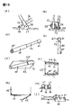
- FIG. 15 shows an example of a simplified diagram of a part of an aircraft fuselage structure that can be used in the present invention
- FIG. 15A shows the components and actuator mechanism of the aircraft as viewed from the direction of extension of the rotating shaft.
- FIG. 15 (B) shows a relationship diagram when FIG. 15 (A) is viewed from the direction perpendicular to the rotation axis, and the component member (57) of the aircraft is rotated by the rotation axis (58).
- Actuator (55) and actuator (56) are connected separately, (56) is a mechanism that is directly fixed to (55) and expands and contracts to change the angle of (55) and (57), and (55) expands and contracts As a result, (57) moves in the longitudinal direction of the aircraft.
- 15A and 15B use an actuator that reciprocates linearly, but the type is not limited, for example, an actuator that rotates such as a hydraulic motor is used in (58).
- FIG. 15C and 15D are simplified views of an example of an actuator that can be used in the present invention.
- the actuator is linearly moved by a cylinder 60 having a rod 59 therein.
- the actuator expands and contracts, and the rotation shaft (61 ′) provided on the rod support portion (61) fixed to the rotation shaft (60 ′) provided on (60) and the rod support portion (59) rotates.
- It is an actuator which moves the angle and composition position of the thrust generator of the present invention.
- (E) in FIG. 15 is a simplified view of the lower part of the nacelle, (62) is a thrust generating device of the present invention having an air inlet, and (62 ′) is a rotation connected to the upper nacelle. It is a ring for.
- FIG. 15 is a simplified view of the lower part of the nacelle, (62) is a thrust generating device of the present invention having an air inlet, and (62 ′) is a rotation connected to the upper nacelle. It is a ring
- FIG. 15F shows an example of a simplified diagram of the vicinity of the rear part of the aircraft according to the present invention, in which a through hole from the upper surface to the lower surface of the rear part of the aircraft of (63) is provided in the vicinity of the horizontal tail of (64). is there.
- FIG. 15G shows a simplified view of an example of a lid that can cover the opening of the suction port of the thrust generating device provided in the lower portion of the thrust generating device, and the nacelle (62) as viewed from the front-rear direction of the aircraft.
- the lid (65) that covers the opening in the left and right double-side opening is shown in the lower part of the door and opens and closes in the direction of the arrow.
- the actuator for the double opening of the door (65) is either a rotary movement or a sliding movement. It may be a thing and those types are not limited.
- 15 (H) and FIG. 15 (I) are simplified views showing an example of a guide mechanism for sliding the structural members of the aircraft installed in the vicinity of the inside of the aircraft in the front-rear direction, and (H) has a rail structure.
- 2 is a cross-sectional view of the sliding guide mechanism as viewed from the front-rear direction of the aircraft, and (I) is a cross-sectional view as viewed from the left-right direction of the aircraft.
- (66) is a connecting portion with the actuator mechanism, and is an example in which the wheel of (67) moves the guide rail of (68) in the direction of the arrow.
- FIG. 16A shows an example of a simplified view of the deflecting plate that can be used in the thrust generating device, as viewed from above.
- FIG. 16A shows the vicinity of the exhaust hole at the rear of the box-shaped nacelle.
- FIG. 16B is a simplified cross-sectional view of FIG. 16A viewed from the side, and the exhaust is deflected in the left-right direction by the rotating shaft of FIG. FIG.
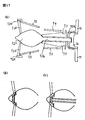
- 17 shows an example of a simplified diagram of a “turbine for gas turbine for connection or integral configuration with a rotating body” according to claim 8 of the present invention, which is connected to a shaft (72b) connected to the turbine (72a).
- a rotor blade having a plurality of blades (72d) fixed radially on the outer periphery of a rotor (72c) that fixes a plurality of blades is an example in which a generator magnet (72e) is installed.
- 17 (A) is provided in a portion corresponding to (2) in FIG. 1, and (73) is for the rotor according to claim 1 of the present invention, which rotates reversely with the rotor (72a) for a low-pressure compressor.
- the outer ring (74) is the outer ring for a rotor according to claim 1 which rotates in the reverse direction with the rotor (75) for a high-pressure compressor, and the rotational directions of (72c) and (75) are the same. Even in the reverse direction, the direction of rotation is arbitrary by the manufacturer.
- (76) is a bearing (76) of (72a to e) and a stationary blade (77) that supports the bearing, and the type thereof is not limited, such as equipment of a fuel injection device for a reburner (after burner).
- FIG. 17B shows a mechanism for generating electric power by rotating the rotor
- FIG. 17C shows a mechanism for generating electric power by rotating the shaft.
- Embodiments of the present invention are as follows. 1. As long as the conditions of the claims of the present invention are satisfied, the shape, material, and type of structure are not limited. 2. Types of the control device for operating the device of the claims of the present invention are not limited as long as they satisfy the claims of the present invention, such as hydraulic pressure, air pressure, motor, screw and gear. 3.
- a low-pressure compressor and a high-pressure compressor are mainly used for explanation, but the structure of the present invention can also be used in an intermediate-pressure compressor, and the compressor may be of an axial flow type.
- the type is not limited. 4).
- the types of combinations of the claims of the present invention with other effects and functions of devices and things are not limited.
- L component of force perpendicular to the flow
- Le leading edge of the blade
- Te trailing edge of the blade
- ch chord
- chL chord length
- V flow direction of fluid
- ⁇ angle of attack
- bup Upper surface of blade
- bun lower surface of blade
- b blade
- bL boundary layer
- ef mainstream
- se separation region
- fw front blade
- rw rear blade
- X line parallel to the rotation axis
- Y vertical line of the jet engine in a direction perpendicular to the line parallel to the rotation axis
- w blade
- W1 blade located in the front row
- W2 blade located in the back row
- LX axial reference line
- LY radial line of the axial compressor
- Sa stagger angle
- sw stationary blade
- R rotor
- 1 Rotating body of axial compressor
- 2 casing
- 3 space for bypass
- 3 ′ space constituted by nozzles for high temperature core flow
- 4 Rotating
Landscapes
- Engineering & Computer Science (AREA)
- Mechanical Engineering (AREA)
- General Engineering & Computer Science (AREA)
- Structures Of Non-Positive Displacement Pumps (AREA)
Abstract
L'invention concerne un dispositif de production de poussée, qui possède un compression à écoulement axial, conçu de sorte que, pour des rotors du compresseur à écoulement axial dans lequel une pluralité d'étages de rangées d'aubes sont concentriques et tournent en alternance en sens inverse, les aubes inclinées dans une direction le long de la direction depuis laquelle l'air est acheminée peuvent être placées dans un étage avant et le rotor d'étage arrière suivant, et l'arbre rotatif des rotors tournant vers l'avant et vers l'arrière forme un corps rotatif pour rotation vers l'avant sur lequel une pluralité de rangées de rotors sont agencées, et un corps rotatif qui tourne en alternance en arrière sur lequel une pluralité de rangées de rotors sont agencées.
Priority Applications (1)
| Application Number | Priority Date | Filing Date | Title |
|---|---|---|---|
| JP2015556859A JPWO2015105202A1 (ja) | 2014-03-19 | 2015-01-13 | 推力発生用装置 |
Applications Claiming Priority (4)
| Application Number | Priority Date | Filing Date | Title |
|---|---|---|---|
| JP2014-002440 | 2014-01-09 | ||
| JP2014002440 | 2014-01-09 | ||
| JP2014-056443 | 2014-03-19 | ||
| JP2014056443 | 2014-03-19 |
Publications (1)
| Publication Number | Publication Date |
|---|---|
| WO2015105202A1 true WO2015105202A1 (fr) | 2015-07-16 |
Family
ID=53524022
Family Applications (1)
| Application Number | Title | Priority Date | Filing Date |
|---|---|---|---|
| PCT/JP2015/051742 Ceased WO2015105202A1 (fr) | 2014-01-09 | 2015-01-13 | Dispositif de production de poussée |
Country Status (1)
| Country | Link |
|---|---|
| WO (1) | WO2015105202A1 (fr) |
Cited By (2)
| Publication number | Priority date | Publication date | Assignee | Title |
|---|---|---|---|---|
| CN107489649A (zh) * | 2017-09-07 | 2017-12-19 | 珠海格力电器股份有限公司 | 轴流风机 |
| CN114109578A (zh) * | 2020-08-26 | 2022-03-01 | 罗伯特·博世有限公司 | 包括同轴反向旋转风扇的风扇模块 |
Citations (5)
| Publication number | Priority date | Publication date | Assignee | Title |
|---|---|---|---|---|
| US2689681A (en) * | 1949-09-17 | 1954-09-21 | United Aircraft Corp | Reversely rotating screw type multiple impeller compressor |
| US3385509A (en) * | 1965-12-02 | 1968-05-28 | Snecma | Gas turbine engines having contrarotating compressors |
| US6220906B1 (en) * | 1999-10-04 | 2001-04-24 | The United States Of America As Represented By The Secretary Of The Navy | Marine propulsion assembly |
| JP2004232601A (ja) * | 2003-01-31 | 2004-08-19 | Koyo Seiko Co Ltd | 軸流圧縮機 |
| JP2005226642A (ja) * | 2004-02-11 | 2005-08-25 | Snecma Moteurs | 二重反転可能な低圧圧縮機に固定された2つの二重反転可能なファンを有するターボジェット |
-
2015
- 2015-01-13 WO PCT/JP2015/051742 patent/WO2015105202A1/fr not_active Ceased
Patent Citations (5)
| Publication number | Priority date | Publication date | Assignee | Title |
|---|---|---|---|---|
| US2689681A (en) * | 1949-09-17 | 1954-09-21 | United Aircraft Corp | Reversely rotating screw type multiple impeller compressor |
| US3385509A (en) * | 1965-12-02 | 1968-05-28 | Snecma | Gas turbine engines having contrarotating compressors |
| US6220906B1 (en) * | 1999-10-04 | 2001-04-24 | The United States Of America As Represented By The Secretary Of The Navy | Marine propulsion assembly |
| JP2004232601A (ja) * | 2003-01-31 | 2004-08-19 | Koyo Seiko Co Ltd | 軸流圧縮機 |
| JP2005226642A (ja) * | 2004-02-11 | 2005-08-25 | Snecma Moteurs | 二重反転可能な低圧圧縮機に固定された2つの二重反転可能なファンを有するターボジェット |
Cited By (6)
| Publication number | Priority date | Publication date | Assignee | Title |
|---|---|---|---|---|
| CN107489649A (zh) * | 2017-09-07 | 2017-12-19 | 珠海格力电器股份有限公司 | 轴流风机 |
| CN107489649B (zh) * | 2017-09-07 | 2023-08-25 | 珠海格力电器股份有限公司 | 轴流风机 |
| CN114109578A (zh) * | 2020-08-26 | 2022-03-01 | 罗伯特·博世有限公司 | 包括同轴反向旋转风扇的风扇模块 |
| US20220065259A1 (en) * | 2020-08-26 | 2022-03-03 | Robert Bosch Gmbh | Fan Module including Coaxial Counter Rotating Fans |
| US11655824B2 (en) * | 2020-08-26 | 2023-05-23 | Robert Bosch Llc | Fan module including coaxial counter rotating fans |
| CN114109578B (zh) * | 2020-08-26 | 2026-06-02 | 罗伯特·博世有限公司 | 包括同轴反向旋转风扇的风扇模块 |
Similar Documents
| Publication | Publication Date | Title |
|---|---|---|
| CN112392562B (zh) | 用于轴承的弹簧指环支承组件 | |
| EP2971551B1 (fr) | Soufflante à basse vitesse pour turbines à gaz | |
| US11668316B1 (en) | Rotor formed of multiple metals | |
| US20200386189A1 (en) | High Speed Aircraft Flight Technologies | |
| US12291980B2 (en) | Unducted rectifier for a turbomachine, turbomachine module and aircraft turbomachine | |
| JP2017096268A (ja) | 可変ピッチファンアクチュエータ | |
| US10677090B2 (en) | Component having co-bonded composite and metal rings and method of assembling same | |
| CN114555953A (zh) | 涡轮机和用于压缩机操作的系统 | |
| US11286795B2 (en) | Mount for an airfoil | |
| US20200239146A1 (en) | De-icing system | |
| WO2018186925A2 (fr) | Turbine rotative inversée dotée d'un ensemble d'engrenage de réduction d'inversion | |
| US20060018761A1 (en) | Adaptable fluid flow device | |
| US8016227B2 (en) | Non-handed engine cowl doors for fuselage mounted turbine engines | |
| CA2891864A1 (fr) | Rotor a pas variable dote de contrepoids eloignes | |
| US12110903B2 (en) | Variable pitch fan of a gas turbine engine | |
| US10294821B2 (en) | Interturbine frame for gas turbine engine | |
| JPWO2015105202A1 (ja) | 推力発生用装置 | |
| JP2016130509A (ja) | 推力発生用装置 | |
| JP2017125416A (ja) | 推力発生用装置 | |
| US12480417B2 (en) | Cold spray duct for a gas turbine engine | |
| JP2024015642A (ja) | 推力発生用装置 | |
| CN111486130A (zh) | 除冰系统 | |
| CN119677934A (zh) | 具有附接组件的定子轮叶组件 | |
| US12188374B2 (en) | Turbine engine with component having a cooling hole with a layback surface | |
| WO2021124205A1 (fr) | Procédé d'amélioration du rapport de pression à l'aide de doubles cônes symétriques ou asymétriques intégrés de base |
Legal Events
| Date | Code | Title | Description |
|---|---|---|---|
| 121 | Ep: the epo has been informed by wipo that ep was designated in this application |
Ref document number: 15734932 Country of ref document: EP Kind code of ref document: A1 |
|
| NENP | Non-entry into the national phase |
Ref country code: DE |
|
| ENP | Entry into the national phase |
Ref document number: 2015556859 Country of ref document: JP Kind code of ref document: A |
|
| 122 | Ep: pct application non-entry in european phase |
Ref document number: 15734932 Country of ref document: EP Kind code of ref document: A1 |