WO2015107656A1 - Appareil de mesure optique - Google Patents
Appareil de mesure optique Download PDFInfo
- Publication number
- WO2015107656A1 WO2015107656A1 PCT/JP2014/050693 JP2014050693W WO2015107656A1 WO 2015107656 A1 WO2015107656 A1 WO 2015107656A1 JP 2014050693 W JP2014050693 W JP 2014050693W WO 2015107656 A1 WO2015107656 A1 WO 2015107656A1
- Authority
- WO
- WIPO (PCT)
- Prior art keywords
- light
- optical
- light emitting
- emitting element
- measuring device
- Prior art date
- Legal status (The legal status is an assumption and is not a legal conclusion. Google has not performed a legal analysis and makes no representation as to the accuracy of the status listed.)
- Ceased
Links
Images




Classifications
-
- G—PHYSICS
- G01—MEASURING; TESTING
- G01J—MEASUREMENT OF INTENSITY, VELOCITY, SPECTRAL CONTENT, POLARISATION, PHASE OR PULSE CHARACTERISTICS OF INFRARED, VISIBLE OR ULTRAVIOLET LIGHT; COLORIMETRY; RADIATION PYROMETRY
- G01J1/00—Photometry, e.g. photographic exposure meter
- G01J1/02—Details
- G01J1/0228—Control of working procedures; Failure detection; Spectral bandwidth calculation
-
- G—PHYSICS
- G01—MEASURING; TESTING
- G01J—MEASUREMENT OF INTENSITY, VELOCITY, SPECTRAL CONTENT, POLARISATION, PHASE OR PULSE CHARACTERISTICS OF INFRARED, VISIBLE OR ULTRAVIOLET LIGHT; COLORIMETRY; RADIATION PYROMETRY
- G01J1/00—Photometry, e.g. photographic exposure meter
- G01J1/42—Photometry, e.g. photographic exposure meter using electric radiation detectors
- G01J1/4228—Photometry, e.g. photographic exposure meter using electric radiation detectors arrangements with two or more detectors, e.g. for sensitivity compensation
-
- G—PHYSICS
- G01—MEASURING; TESTING
- G01J—MEASUREMENT OF INTENSITY, VELOCITY, SPECTRAL CONTENT, POLARISATION, PHASE OR PULSE CHARACTERISTICS OF INFRARED, VISIBLE OR ULTRAVIOLET LIGHT; COLORIMETRY; RADIATION PYROMETRY
- G01J3/00—Spectrometry; Spectrophotometry; Monochromators; Measuring colours
- G01J3/46—Measurement of colour; Colour measuring devices, e.g. colorimeters
- G01J3/50—Measurement of colour; Colour measuring devices, e.g. colorimeters using electric radiation detectors
-
- G—PHYSICS
- G01—MEASURING; TESTING
- G01J—MEASUREMENT OF INTENSITY, VELOCITY, SPECTRAL CONTENT, POLARISATION, PHASE OR PULSE CHARACTERISTICS OF INFRARED, VISIBLE OR ULTRAVIOLET LIGHT; COLORIMETRY; RADIATION PYROMETRY
- G01J1/00—Photometry, e.g. photographic exposure meter
- G01J1/42—Photometry, e.g. photographic exposure meter using electric radiation detectors
- G01J2001/4247—Photometry, e.g. photographic exposure meter using electric radiation detectors for testing lamps or other light sources
- G01J2001/4252—Photometry, e.g. photographic exposure meter using electric radiation detectors for testing lamps or other light sources for testing LED's
Definitions
- the present invention relates to an optical measuring device.
- Patent Document 1 discloses an inspection apparatus that performs optical inspection of LEDs (Light Emitting Diodes).
- an example of the subject of the present invention is to provide an optical measuring device having a simple configuration that can obtain a highly reliable measurement result by measuring optical characteristics of a light emitting element.
- An optical measuring device detects a light emitted from a light emitting element and measures an optical characteristic of the detected light, and has a wider dynamic range than the first measuring device, Based on a second measuring device that detects light emitted from the light emitting element and measures an optical characteristic of the detected light, and a light quantity that is one of the optical characteristics measured by the second measuring device, the first measurement is performed. And a control unit for determining whether or not the measurement result of the vessel is valid.
- FIG. 1 shows a light emission state of a light emitting element measured by an optical measuring device.
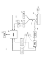
- FIG. 2 schematically shows the configuration of the optical measurement apparatus.
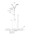
- FIG. 3 shows an enlarged view of an optical fiber and a light emitting element included in the optical measuring device.
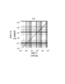
- FIG. 4 shows the photoelectric conversion characteristics of the photodetector.
- FIG. 5A shows the photoelectric conversion characteristics of the spectrometer.
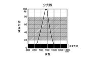
- FIG. 5B shows an example of the spectral characteristics of the light emitting element measured with a spectroscope.
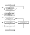
- FIG. 6 is a flowchart for explaining processing performed by the control unit of the optical measurement apparatus when measuring optical characteristics.
- FIG. 7 is a diagram for explaining a first modification of the optical measuring device.
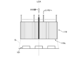
- FIG. 8A is a diagram for explaining a second modification of the optical measuring device.
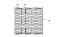
- FIG. 8B shows a view of the light emitting element and the bundle fiber shown in FIG. 8A viewed from the direction of the light emission central axis.
- FIG. 9 is a diagram for explaining a third modification of the optical measuring device.
- FIG. 10 is a diagram for explaining a fourth modification of the optical measuring device.
- FIG. 11 is a flowchart for explaining processing performed by the control unit shown in FIG. 10 when measuring optical characteristics.
- FIG. 12 shows another arrangement example of the light quantity adjuster shown in FIG.
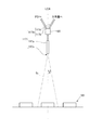
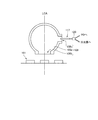
- FIG. 1 shows a light emission state of the light emitting element 101 measured by the optical measuring device 3.
- the light-emitting element 101 includes at least an electrode and a light-emitting portion, and emits light in a specific wavelength region when power is supplied.
- the light emitting element 101 is, for example, a light emitting diode. As shown in FIG. 1A, the light emitting element 101 emits light radially from the light emitting surface 101a.
- the light emitting surface 101 a is located on the surface of the light emitting element 101.
- the normal line of the light emitting surface 101a of the light emitting element 101 is referred to as a light emission central axis LCA.
- the light emitting surface 101a is the surface of the light emitting element 101 on the positive direction side of the light emission central axis LCA in FIG.
- a counterclockwise angle from the x axis on the plane is defined as ⁇ .
- ⁇ an angle formed with the light emission center axis LCA when ⁇ is fixed.
- the intensity of light emitted from the light emitting element 101 and emitted from the light emitting surface 101a varies depending on the angle ⁇ from the light emission center axis LCA and the like.
- the amount of light is calculated for the back side of the light emitting element 101 by integrating all the intensities of light within the range of ⁇ values of 0 ° to 90 ° for ⁇ values of 0 ° to 360 °. It is the added value. Knowing this amount of light makes it possible to inspect whether or not the light emitting element 101 is suitable for various uses.
- the intensity of light emitted from the light emitting element 101 has different values for each of ⁇ and ⁇ .
- a diagram as shown in FIG. 1B is used.
- FIG. 1C is a cross-sectional view at a position where the value of ⁇ is constant.
- the light intensity at the same distance from the light emitting element 101 and at the position of the angle ⁇ from the light emission central axis LCA is defined as the light distribution intensity E ( ⁇ ).
- This light distribution intensity E ( ⁇ ) corresponding to each ⁇ is illustrated as a light distribution intensity distribution.
- the amount of light on the back side of the light emitting element 101 can be obtained by multiplying K ( ⁇ ) by a constant coefficient ⁇ . Then, the light amount of the light emitting element 101 can be obtained by adding the light amount K ( ⁇ ) on the front surface side and the light amount K ( ⁇ ) ⁇ ⁇ on the back surface side. Note that it is known that the difference between the light amount on the front surface side and the light amount on the back surface side of the light emitting element 101 is substantially constant in the light emitting element 101 manufactured in the same process. For this reason, if the coefficient ⁇ is obtained by actually measuring the light amount of one light emitting element 101, the same value can be applied to the other light emitting elements 101.
- the light emitting element 101 can be considered as a point by measuring at a position sufficiently far from the light emitting element 101. Since the light emitting element 101 is extremely small as compared with the normal photodetector 105 or the like (see FIG. 2), it can be assumed in this way. The same applies to the description after FIG. 2 unless otherwise specified.
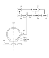
- FIG. 2 schematically shows the configuration of the optical measuring device 3.
- FIG. 3 shows an enlarged view of the optical fiber 117 and the light emitting element 101 included in the optical measuring device 3.
- the optical measuring device 3 is a device that measures the optical characteristics of the light emitted from the light emitting element 101.
- the optical characteristics measured by the optical measuring device 3 include at least the light amount, wavelength, and chromaticity of the light emitted from the light emitting element 101.
- the optical measuring device 3 supplies power to the light emitting element 101 to emit light, and measures the optical characteristics of the light emitted from the light emitting element 101. If a plurality of light emitting elements 101 are arranged, the optical measuring device 3 sequentially supplies power to the light emitting element 101 to be measured among the light emitting elements 101 arranged in a plurality, and the light emitting element 101 to be measured emits light. Measure the optical properties of the light.
- the optical measuring device 3 can be applied to an inspection device used in an inspection process included in the manufacturing process of the light emitting element 101.
- the optical measuring device 3 can measure electrical characteristics in addition to the optical characteristics of the light emitting element 101.
- the optical measurement device 3 includes a table 103, a probe needle 109, an optical fiber 117, a signal line 111, a photodetector 105, an amplifier 113, a spectroscope 121, an electrical characteristic measurement unit 125, a control unit 151, And at least an output unit 163.
- the table 103 is a measurement sample stage on which the light emitting element 101 to be measured is placed.
- the table 103 has a substantially uniform flat plate shape and is installed substantially horizontally.
- the table 103 and the light emitting element 101 mounted thereon are substantially parallel to each other.
- the table 103 includes at least a glass table 103a and a dicing sheet 103b.
- the glass table 103a is formed in a substantially uniform flat plate shape using a light transmitting material such as sapphire or glass.
- the dicing sheet 103b has adhesiveness on the surface and is laminated on the glass table 103a.
- the light emitting element 101 is placed on the dicing sheet 103b.
- the table 103 having the dicing sheet 103b can easily transfer the light emitting element 101 to the table 103 at the time of measurement, and can suppress displacement.
- the light emitting element 101 when a plurality of the light emitting elements 101 are arranged in advance on the dicing sheet 103b, the light emitting element 101 and the dicing sheet 103b may be collectively placed on the glass table 103a. Good.
- the probe needle 109 supplies power to the light emitting element 101 to cause the light emitting element 101 to emit light.
- the probe needles 109 extend radially in a direction perpendicular to the normal line of the light emitting element 101 substantially parallel to the light emitting surface 101 a of the light emitting element 101.
- the probe needle 109 in FIG. 2 applies a voltage in contact with the electrode of the light emitting element 101 when measuring the optical characteristics of the light emitting element 101.
- the probe needle 109 is connected to the electrical characteristic measuring unit 125, and the electrical characteristics of the light emitting element 101 can be measured simultaneously.
- the probe needle 109 is disposed on the upper surface, the lower surface, or both surfaces of the light emitting element 101 according to the position of the electrode of the light emitting element 101.
- the probe needle 109 When the probe needle 109 is brought into contact with the light emitting element 101, the probe needle 109 may be moved while the table 103 and the light emitting element 101 are fixed. Conversely, the table 103 and the light emitting element 101 may be moved while the probe needle 109 is fixed.
- the optical fiber 117 takes in the light emitted from the light emitting element 101 and guides it to the photodetector 105 and the spectroscope 121.
- the optical fiber 117 takes in light with a predetermined numerical aperture.
- the optical fiber 117 includes a head 117a, an optical transmission line 117b, and an incident port 117c.
- the head 117a is a part that captures light.
- the head 117a is formed in a cylindrical shape.
- An incident port 117c which is an opening for allowing light to enter, is provided at the tip of the head 117a.
- the head 117 a is disposed so that the incident port 117 c faces the light emitting surface 101 a of the light emitting element 101.
- the central axis of the incident port 117c substantially coincides with the light emission central axis LCA of the light emitting element 101 to be measured.
- the central axis of the head 117a substantially coincides with the central axis of the incident port 117c.
- the incident port 117c allows light in a range corresponding to a predetermined numerical aperture of the optical fiber 117 to enter.
- the optical transmission path 117b optically connects the end of the head 117a provided with the incident port 117c on the side opposite to the tip, and the photodetector 105 and the spectroscope 121.
- the end of the optical transmission line 117b opposite to the tip of the head 117a is branched into a first path 117d and a second path 117e.
- the first path 117 d extends toward the spectroscope 121 and is connected to the spectroscope 121.
- the second path 117 e extends toward the photo detector 105 and is connected to the photo detector 105.
- the optical transmission path 117 b guides the light incident from the incident port 117 c to the photodetector 105 and the spectroscope 121.
- the light transmission path 117b totally reflects the light incident from the incident port 117c and guides the light to the photodetector 105 and the spectroscope 121 while suppressing transmission loss as much as possible.
- the photodetector 105 detects the light emitted from the light emitting element 101 via the optical fiber 117 and measures the optical characteristics thereof.
- the optical characteristics measured by the photodetector 105 include at least the amount of light emitted from the light emitting element 101.
- the photodetector 105 includes a light receiving element. When incident light is incident on the light receiving element, the photodetector 105 generates a charge corresponding to the incident light by photoelectric conversion.
- the light receiving element of the photodetector 105 is, for example, a photodiode.
- the photodetector 105 adds up all the light intensities of the incident light and obtains the amount of the incident light.
- the photodetector 105 generates an electrical signal according to the obtained light amount.
- the photodetector 105 outputs the generated electric signal to the amplifier 113 via the signal line 111. This electric signal corresponds to the light amount information measured by the photodetector 105.
- the amplifier 113 amplifies the electrical signal output from the photodetector 105 and outputs the amplified signal to the control unit 151.
- the spectroscope 121 detects the light emitted from the light emitting element 101 via the optical fiber 117 and measures the optical characteristics thereof.
- the optical characteristics measured by the spectroscope 121 include at least the light amount, wavelength, and chromaticity of the light emitted from the light emitting element 101.
- the spectroscope 121 includes a light receiving element. When light enters the light receiving element, the spectroscope 121 generates a charge corresponding to the incident light by photoelectric conversion.
- the light receiving element of the spectroscope 121 is, for example, a CCD (Charge Coupled Device), a photodiode array, or the like.
- the spectroscope 121 wavelength-disperses incident light and determines the light intensity for each dispersed wavelength.
- the light intensity for each wavelength corresponds to the wavelength spectrum information of the incident light.
- the spectroscope 121 calculates component ratios of tristimulus values of red (R), green (G), and blue (B) from the wavelength spectrum information, and obtains the chromaticity of incident light.
- the spectroscope 121 integrates the light intensity for each dispersed wavelength to obtain the amount of incident light.
- the spectroscope 121 can obtain other optical characteristics as necessary.
- the spectroscope 121 generates an electrical signal corresponding to the obtained various optical characteristics.
- the spectroscope 121 outputs the generated electrical signal to the control unit 151 via the signal line 111. This electrical signal corresponds to wavelength spectrum information, chromaticity information, light amount information, and the like measured by the spectroscope 121.
- the distance between the light emitting element 101 to be measured and the optical fiber 117 is L.
- A be the distance from the center of the light emitting element 101 to be measured to the outer edge.
- B be the interval between adjacent light emitting elements 101.
- X be the distance from the center of the light emitting element 101 to be measured to the outer edge of the light emitting element 101 adjacent to the light emitting element 101 to be measured.
- the numerical aperture of the optical fiber 117 and NA the range indicated by the numerical aperture NA and S 0.
- D the distance from the center of the light emitting element 101 to the outer edge of the range S 0 when the range S 0 is projected onto the light emitting element 101.
- NA sin ⁇
- D Ltan ⁇ .
- the light emitting element 101 When the light emitting element 101 is in the range S 0 indicated by the numerical aperture NA, the light emitted from the light emitting element 101 can be totally reflected in the optical fiber 117 and guided to the photodetector 105 and the spectroscope 121. If there is no light emitting element 101 in the range S 0 , the light emitted from the light emitting element 101 is not guided to the photodetector 105 and the spectroscope 121. Therefore, the range S 0 indicated by the numerical aperture NA corresponds to the range of light that can be detected by the photodetector 105 and the spectroscope 121.
- the range of light detected by the photodetector 105 and the spectroscope 121 is also referred to as a “detection range”.
- the detection range of the photodetector 105 and the spectroscope 121 corresponds to a range of light in which the optical measurement device 3 can measure optical characteristics.
- the light emitting element 101 to be measured is positioned within the range S 0, and, for the light emitting element 101 other than the measurement object is not located within the range S 0, satisfying the relation of the following type distance L is set in advance.
- a / tan ⁇ ⁇ L ⁇ X / tan ⁇ As a result, the optical measurement device 3 does not detect unintended light emitted from the light emitting elements 101 other than the measurement target in a state where the plurality of light emitting elements 101 are arranged, and the light emitted from the measurement light emitting element 101 emits light. Can be detected.
- “Unintended light emitted from the light emitting element 101 other than the measurement target” is light emitted from the light emitting element 101 other than the measurement target due to light emission of the light emitting element 101 as the measurement target. For example, there is light emitted when light emitted from the light emitting element 101 to be measured enters the light emitting element 101 other than the measurement target and the light emitting elements 101 other than the measurement target are excited. For example, there is light emitted when light emitted from the light emitting element 101 to be measured enters the light emitting element 101 other than the measurement target and is reflected by the light emitting element 101 other than the measurement target.
- the electrical property measurement unit 125 includes at least a positioning unit 159, an HV unit 153, an ESD unit 155, and a switching unit 157.
- the positioning unit 159 positions and fixes the probe needle 109. Specifically, the positioning unit 159 has a function of holding the tip position of the probe needle 109 at a fixed position as long as the table 103 moves. Conversely, if the positioning unit 159 is of a type in which the probe needle 109 moves, the position of the tip of the probe needle 109 is moved to a predetermined position on the table 103 on which the light emitting element 101 is placed, and then the position It has the function to hold.
- the HV unit 153 applies a rated voltage and detects various electrical characteristics of the light emitting element 101 with respect to the rated voltage.
- the photodetector 105 and the spectroscope 121 measure the light emitted from the light emitting element 101 in a state where the voltage from the HV unit 153 is applied.
- Various characteristic information detected by the HV unit 153 is output to the control unit 151.
- the ESD unit 155 is a unit for inspecting whether or not electrostatic discharge is caused by applying a large voltage to the light emitting element 101 for an instant to cause electrostatic discharge.
- the electrostatic breakdown information detected by the ESD unit 155 is output to the control unit 151.
- the switching unit 157 switches between the HV unit 153 and the ESD unit 155.
- the voltage applied to the light emitting element 101 via the probe needle 109 is changed by the switching unit 157. And by this change, the inspection item of the light emitting element 101 is changed to detect various characteristics at the rated voltage or to detect the presence or absence of electrostatic breakdown.
- the control unit 151 comprehensively controls the operation of the optical measurement device 3.
- the control unit 151 receives light amount information measured by the photodetector 105.
- the control unit 151 receives wavelength spectrum information, chromaticity information, and light amount information measured by the spectroscope 121.
- the control unit 151 receives various electrical characteristic information output by the HV unit 153.
- the control unit 151 receives the electrostatic breakdown information detected by the ESD unit 155.
- the control unit 151 separates and analyzes various characteristics of the light emitting element 101 from these inputs. After analyzing the various characteristics, the control unit 151 outputs the analysis result from the output unit 163 such as image output. Furthermore, the control part 151 controls each component of the optical measuring device 3 as needed based on the analysis result.
- FIG. 4 shows the photoelectric conversion characteristics of the photodetector 105.
- FIG. 5A shows the photoelectric conversion characteristics of the spectroscope 121.
- the VI characteristic varies according to the light intensity of the incident light (varies in the negative direction with respect to the current axis).
- a short-circuit current proportional to the amount of incident light flows through the photodetector 105. Since the short-circuit current is proportional to the number of charges generated by incident light, it is proportional to the amount of incident light. Therefore, the relationship between the illuminance indicating the amount of incident light per unit area and the short-circuit current represents the photoelectric conversion characteristics of the photodetector 105.
- the linearity in the photoelectric conversion characteristics of the photodetector 105 is an index indicating the measurement performance of the photodetector 105.
- “linearity” means that the input and the output are in a proportional relationship.
- the linearity in the photoelectric conversion characteristics of the photodetector 105 is that the incident light amount and the output current are in a proportional relationship.
- a range in which a proportional relationship between input and output is established is called “dynamic range”.
- the dynamic range is a range where linearity is established.
- the dynamic range in the photoelectric conversion characteristics of the photodetector 105 is a range in which a proportional relationship between the incident light amount and the output current is established, and is a range in which linearity in the photoelectric conversion characteristics is established.
- the photodetector 105 has a wide dynamic range as shown in FIG. 4A. Although not shown, the photodetector 105 can measure the amount of light with high reproducibility.
- the dynamic range of the photoelectric conversion characteristics of the spectroscope 121 is significantly narrower than that of the photodetector 105 as shown in FIG. 5A.
- the incident light quantity can be adjusted by changing the exposure time to the spectroscope 121, and the measurement range of the photoelectric conversion characteristics can be expanded.
- the dynamic range of the photoelectric conversion characteristics of the spectroscope 121 is narrower by 5 digits or more than that of the photodetector 105.
- FIG. 5B shows an example of the spectral characteristics of the light emitting element measured by the spectroscope 121.
- FIG. 5B shows an example in which the spectroscope 121 measures the spectral characteristics of an element that emits light in a specific wavelength region when power is supplied.
- the spectroscope 121 has a relative intensity of 10% or less in a wavelength region shorter than 870 nm or a wavelength region larger than 1000 nm, which is a poor sensitivity. For this reason, the spectroscope 121 cannot measure the light quantity of light in a wavelength region shorter than 870 nm or in a wavelength region larger than 1000 nm.
- the spectroscope 121 indicates a range where the light quantity cannot be measured by the spectroscope 121.
- the spectroscope 121 when used in a range where the relative intensity is 20 to 80% in order to obtain a light quantity with a constant measurement accuracy, the spectroscope 121 only emits light quantity for light in the wavelength regions of 880 nm to 920 nm and 950 nm to 990 nm. It cannot be measured. This is because when the relative intensity is in the range of 20% or less or in the range of 80% or more, the linearity in the photoelectric conversion characteristics of the spectroscope 121 is lowered and the measurement accuracy is lowered.
- the shaded area in FIG. 5B indicates a range in which the spectroscope 121 can measure the amount of light. Although not shown, the spectroscope 121 cannot measure the amount of light with a reproducibility as high as that of the photodetector 105.
- the measurement result of the spectroscope 121 may be inaccurate depending on the amount of light incident on the spectroscope 121. Therefore, a technique capable of measuring the optical characteristics of the light emitting element 101 with high reliability is desired.
- the light emitted from the light emitting element 101 to be measured enters the optical fiber 117.
- the optical transmission path 117b of the optical fiber 117 is branched and connected to the photodetector 105 and the spectroscope 121, respectively.
- Light emitted from the light emitting element 101 to be measured is incident on the optical fiber 117 and then guided to the photodetector 105 and the spectroscope 121.
- the photodetector 105 measures the amount of the detected light.
- the photodetector 105 outputs the light quantity measurement result to the control unit 151.
- the spectroscope 121 detects the light guided by the optical fiber 117, the spectroscope 121 measures various optical characteristics including the amount of the detected light.
- the spectroscope 121 outputs measurement results of various optical characteristics including the light amount to the control unit 151. That is, the optical characteristics measured by the photodetector 105 and the spectroscope 121 are the optical characteristics of the same light emitting element 101.
- the control unit 151 that comprehensively controls the operation of the optical measurement apparatus 3 mainly performs the following processing when measuring the optical characteristics.
- FIG. 6 is a flowchart for explaining processing performed by the control unit 151 of the optical measurement device 3 when measuring optical characteristics.
- step S ⁇ b> 10 the control unit 151 determines whether the light amount measurement result of the photodetector 105 and the measurement result of the spectroscope 121 are input.
- the control unit 151 waits until the light amount measurement result of the photodetector 105 and the measurement result of the spectroscope 121 are input.
- the control unit 151 associates each result and stores them in a predetermined storage area. And the control part 151 transfers to step S20.
- step S ⁇ b> 20 the control unit 151 verifies the validity of the measurement result of the spectroscope 121 based on the light amount measurement result of the photodetector 105.
- the control unit 151 can verify the validity of the measurement result of the spectroscope 121 by, for example, the following method.
- control unit 151 confirms the light quantity measurement result included in the measurement result of the spectroscope 121 input in step S10. And the control part 151 calculates
- control unit 151 stores in advance a range of the light quantity measurement result of the spectroscope 121 that can be acquired within the dynamic range in the photoelectric conversion characteristics of the spectroscope 121. Then, the control unit 151 determines whether or not the light quantity measurement result of the photodetector 105 input in step S10 is within the range of the light quantity measurement result of the spectroscope 121 stored in advance. Then, if the light amount measurement result of the photodetector 105 input in step S10 is within the range of the light amount measurement result of the spectroscope 121 stored in advance, the control unit 151 of the spectroscope 121 input in step S10. The measurement result is judged to be appropriate.
- step S10 determines whether the light quantity measurement result of the photodetector 105 input in step S10 is within the range of the light quantity measurement result of the spectroscope 121 stored in advance. If the light quantity measurement result of the photodetector 105 input in step S10 is not within the range of the light quantity measurement result of the spectroscope 121 stored in advance, the control unit 151 of the spectroscope 121 input in step S10. Judge that the measurement results are not valid.
- step S30 the control unit 151 determines whether or not the measurement result of the spectroscope 121 is valid. If it is determined by the verification in step S20 that the measurement result of the spectroscope 121 is valid, the control unit 151 proceeds to step S40. On the other hand, if it is determined by the verification in step S20 that the measurement result of the spectroscope 121 is not valid, the control unit 151 proceeds to step S60.
- step S40 the control unit 151 validates the measurement result of the spectroscope 121.
- step S ⁇ b> 50 the control unit 151 outputs the measurement result of the spectroscope 121 to the output unit 163. And the control part 151 complete
- step S60 the control unit 151 invalidates the measurement result of the spectroscope 121.
- the optical measurement apparatus 3 selectively validates the measurement result of the spectroscope 121 based on the light amount measurement result measured by the photodetector 105 having a wider dynamic range than the spectroscope 121. For this reason, the optical measuring device 3 can output only a reliable measurement result as valid when measuring the optical characteristics of the light emitting element 101. Therefore, the measurement result of the optical characteristics of the optical measuring device 3 can obtain high reliability.
- FIG. 7 is a diagram for explaining a first modification of the optical measuring device 3.
- the optical measurement device 3 of Modification 1 has a configuration in which an optical waveguide 120 is added to the optical measurement device 3 shown in FIGS.
- the optical transmission path 117 b of the optical fiber 117 may be branched using the optical waveguide 120.
- the optical waveguide 120 branches the optical transmission path 117 b into a first path 117 d toward the spectroscope 121 and a second path 117 e toward the photodetector 105.
- the first path 117d is an optical transmission path 117b that connects the optical waveguide 120 and the spectroscope 121.
- the second path 117 e is an optical transmission path 117 b that connects between the optical waveguide 120 and the photodetector 105.
- the optical waveguide 120 totally guides incident light inside to suppress transmission loss as much as possible, and guides it to the first path 117d and the second path 117e.
- Other configurations of the optical measurement device 3 of Modification 1 are the same as the configurations of the optical measurement device 3 shown in FIGS.
- FIG. 8A is a diagram for explaining a second modification of the optical measuring device 3.
- FIG. 8B shows a view of the light emitting element 101 and the bundle fiber 119 shown in FIG. 8A viewed from the direction of the light emission central axis LCA.
- the optical measurement device 3 of Modification 2 has a configuration in which a bundle fiber 119 is added instead of the optical fiber 117 of the optical measurement device 3 shown in FIGS.
- the bundle fiber 119 is configured by a bundle of a plurality of optical fibers 117.
- the bundle fiber 119 is arranged so that the entrance 119c faces the light emitting surface 101a of the light emitting element 101 to be measured.
- the optical fiber 117 on the central axis of the bundle fiber 119 has its central axis substantially coincident with the light emission central axis LCA of the light emitting element 101 to be measured.
- One or more optical fibers 117 near the central axis of the bundle fiber 119 are connected to the spectrometer 121.
- a plurality of optical fibers 117 other than the vicinity of the central axis of the bundle fiber 119 are connected to the photodetector 105. 8A and 8B, the one or more optical fibers 117 near the central axis of the bundle fiber 119 are shown in black.
- a plurality of optical fibers 117 other than the vicinity of the central axis of the bundle fiber 119 are shown in white.
- the size of the cross section perpendicular to the light emission center axis LCA of the bundle fiber 119 is larger than the light emitting surface 101a of the measurement target 101 and covers a plurality of light emitting elements 101 other than the measurement target.
- the size of Range S 2 indicated the numerical aperture of the fiber bundle 119 is enlarged than the range S 0 indicating the numerical aperture NA of the optical fiber 117.
- the light emitting element 101 other than the measurement object in addition to the light emitting element 101 to be measured also included.
- the range S 2 is expanded more than the range S 0, so that the light emitted from the light-emitting element 101 to be measured is more emitted to the bundle fiber 119 than when the optical fiber 117 is used. Many incidents are possible. Therefore, the optical measuring device 3 of the modification 2 can detect more light with the spectroscope 121 and the photodetector 105, and can measure the amount of light with higher accuracy. The alignment work of the bundle fiber 119 and the like can be performed more easily.
- the photodetector 105 is connected to each of the plurality of optical fibers 117 constituting the bundle fiber 119, the light intensity distribution of the light emitting surface 101a of the light emitting element 101 to be measured is determined. Can be measured.
- the center axis of the bundle fiber 119 substantially coincides with the emission center axis LCA of the light emitting element 101 to be measured, and the optical measurement is performed only by the optical fiber 117 in the vicinity of the center axis of the bundle fiber 119. Connected to the device 121. Therefore, the optical transmission line 117b of the optical fiber 117 can be branched more easily than when the optical waveguide 120 is used. Further, when measuring the chromaticity and the like of the plurality of light emitting elements 101 arranged, the spectroscope 121 detects the above-described “unintended light emitted from the light emitting elements 101 other than the measurement target” described with reference to FIG. In addition, the light emitted from the light emitting element 101 to be measured can be detected. Therefore, the optical measuring device 3 of the modified example 2 can measure chromaticity and the like with high accuracy.
- the size of the cross section of the bundle fiber 119 perpendicular to the light emission center axis LCA is such that it covers only the light emitting element 101 to be measured and does not cover the light emitting element 101 adjacent to the light emitting element 101 to be measured. May be.
- the shape of the cross section perpendicular to the light emission center axis LCA of the bundle fiber 119 may be a circular shape instead of a rectangular shape as shown in FIG. 8B.
- Other configurations of the optical measurement device 3 of Modification 2 are the same as the configurations of the optical measurement device 3 shown in FIGS.
- FIG. 9 is a diagram for explaining a third modification of the optical measuring device 3.
- the optical measurement device 3 of Modification 3 has a configuration in which an integrating sphere 108 is added to the optical measurement device 3 of Modification 1 shown in FIG.
- the integrating sphere 108 is formed in a hollow, substantially spherical shape.
- the integrating sphere 108 includes an inner wall 108a, an inlet 108b, and an outlet 108c.
- the inner wall 108a forms an internal space of the integrating sphere 108.
- the inner wall 108a is formed of a material having high reflectivity and excellent diffusibility.
- the inner wall 108a is provided with an inlet 108b and an outlet 108c.
- the intake port 108b is an opening for capturing light emitted from the light emitting element 101 to be measured.
- the size of the intake port 108b is sufficiently larger than the incident port 117c of the optical fiber 117.
- the opening center axis of the intake port 108b substantially coincides with the light emission center axis LCA of the light emitting element 101 to be measured.
- the intake port 108 b guides the light emitted from the light emitting element 101 to the inside of the integrating sphere 108.
- the light guided into the integrating sphere 108 from the inlet 108b is repeatedly reflected by the inner wall 108a and reaches the outlet 108c.
- the outlet 108 c is an opening for taking out the light reflected by the inner wall 108 a to the outside of the integrating sphere 108.
- the outlet 108c is provided at a position different from the inlet 108b of the inner wall 108a.
- An optical fiber 117 is provided at the outlet 108c in FIG.
- the extraction port 108c in FIG. 9 guides the light reflected by the inner wall 108a to the optical fiber 117.
- the light guided to the optical fiber 117 enters the optical fiber 117 and is guided to the photodetector 105 and the spectroscope 121 via the optical waveguide 120.
- the optical measuring device 3 of Modification 3 captures the light emitted from the light emitting element 101 to be measured through the intake 108b of the integrating sphere 108 that is sufficiently larger than the incident port 117c of the optical fiber 117. Then, the optical measurement device 3 of the third modification causes the light taken in by the integrating sphere 108 to enter the optical fiber 117 provided at the outlet 108c. For this reason, the optical measurement apparatus 3 of the modification 3 can detect more light with the spectroscope 121 and the photodetector 105, and can measure the light quantity with higher accuracy.
- the integrating sphere 108 can be measured with higher accuracy by reducing the opening area of the outlet 108c.
- the integrating sphere has two outlets. Each of the two outlets is provided with two optical fibers. Each of the two optical fibers is connected to a spectroscope and a photodetector. Then, the light taken into the integrating sphere enters each optical fiber provided at the two outlets, and is detected by the spectroscope and the photodetector.
- the integrating sphere 108 shown in FIG. 9 is provided with only one outlet 108c. For this reason, the integrating sphere 108 can have an opening area of the outlet 108c smaller than that of a general integrating sphere. Therefore, the optical measurement device 3 of Modification 3 can measure the optical characteristics of the light emitting element 101 with higher accuracy.
- Other configurations of the optical measurement device 3 of Modification 3 are the same as those of the optical measurement device 3 of Modification 1 shown in FIG.
- FIG. 10 is a diagram for explaining a fourth modification of the optical measuring device 3.
- FIG. 11 is a flowchart for explaining processing performed by the control unit 151 shown in FIG. 10 when measuring optical characteristics.
- FIG. 12 shows another arrangement example of the light amount adjuster 122 shown in FIG.
- the optical measurement device 3 of Modification 4 has a configuration in which a light amount adjuster 122 is added to the optical measurement device 3 of Modification 3 shown in FIG.
- the light emitting elements 101 of different types often have different light emission characteristics depending on the type. Therefore, when measuring the optical characteristics of light emitting elements 101 of different varieties, the amount of light incident on the spectroscope 121 is often different. Therefore, it is necessary to adjust the amount of incident light appropriately for each type of light emitting element 101. However, adjusting the amount of light incident on the spectroscope 121 by changing the measurement environment for each type of the light emitting element 101 has a heavy load.
- the distance between the optical fiber 117 and the light emitting element 101 may be changed.
- the difference in the amount of light deviates by a factor of 100, so the distance between the optical fiber 117 and the light emitting element 101 may need to be changed by a factor of ten.
- the fact that the distance between the optical fiber 117 and the light emitting element 101 must be changed ten times is a great load.
- the chromaticity of the light emitted from the light emitting element 101 changes when the distance is changed, so that the measurement accuracy of the optical characteristics by the spectroscope 121 decreases.
- the optical measurement device 3 of the modification 4 includes a light amount adjuster 122.
- the light amount adjuster 122 adjusts the amount of light detected by the spectroscope 121.
- the light amount adjuster 122 is disposed on the first path 117 d of the optical transmission path 117 b that connects the optical waveguide 120 and the spectroscope 121.
- the light quantity adjuster 122 is configured using an optical filter that attenuates the light quantity, such as an ND filter (Neutral Density Filter).
- the light amount adjuster 122 may be configured using an electro-optic element, a magneto-optic element, an acousto-optic element, a liquid crystal optical element, or the like.
- the light amount adjuster 122 is connected to the control unit 151.
- the light amount adjuster 122 is configured to be able to adjust the amount of attenuation of light passing therethrough.
- the amount of attenuation adjusted by the light amount adjuster 122 is set by the control unit 151.
- the attenuation amount adjusted by the light amount adjuster 122 can be appropriately set so that the incident light amount to the spectroscope 121 falls within the dynamic range in the photoelectric conversion characteristics of the spectroscope 121.
- the attenuation may be set differently mainly depending on the type of the light emitting element 101.
- the light amount adjuster 122 also has a configuration that can reduce the attenuation amount to zero.
- step S10 to step S60 the control unit 151 performs the same processing as in step S10 to step S50 shown in FIG.
- step S ⁇ b> 70 the control unit 151 controls the light amount adjuster 122.
- the control unit 151 confirms the measurement result of the spectroscope 121 invalidated in step S60 and the light amount measurement result of the photodetector 105 associated with the result.
- the control part 151 calculates
- the control unit 151 outputs a control signal including the obtained attenuation amount to the light amount adjuster 122 and sets the attenuation amount in the light amount adjuster 122.
- the control unit 151 can obtain the attenuation amount adjusted by the light amount adjuster 122 by, for example, the following method.
- control unit 151 obtains and verifies the difference between the light amount measurement result of the spectroscope 121 and the light amount measurement result of the photodetector 105 in the verification in step S20, the difference is within the allowable range of the difference. Find the amount of attenuation that will fit.
- step S20 when the verification is performed using the range of the light quantity measurement result of the spectroscope 121 that can be acquired within the dynamic range in the photoelectric conversion characteristics of the spectroscope 121, the following is performed. Asking. That is, the control unit 151 obtains the attenuation amount adjusted by the light amount adjuster 122 according to the difference between the threshold value in the range and the light amount measurement result of the photodetector 105.
- step S80 the control unit 151 instructs the photodetector 105 and the spectroscope 121 to perform measurement again.
- the control unit 151 outputs a control signal to the photo detector 105 and the spectroscope 121 and instructs the photo detector 105 and the spectroscope 121 to perform measurement again.
- the spectroscope 121 can detect the light attenuated by the attenuation set in step S70 and measure the optical characteristics. Then, the measurement result of the spectroscope 121 that has been measured again is input to the control unit 151 again and verified in step S20. Thereby, the measurement result of the spectroscope 121 output in step S50 is only the measurement with high reliability.
- the optical measurement device 3 of the modification 4 selectively validates the measurement result of the spectroscope 121 based on the light amount measurement result measured by the photodetector 105 having a wider dynamic range than the spectroscope 121. For this reason, the optical measuring device 3 of the modified example 4 can output only reliable measurement results as effective when measuring the optical characteristics of the light emitting element 101. Therefore, the measurement result of the optical characteristics of the optical measurement device 3 of the modification 4 can obtain high reliability.
- the optical measuring device 3 of the modification 4 can automatically adjust the incident light to the spectroscope 121 to an appropriate light amount. And the optical measuring device 3 of the modification 4 can measure the optical characteristic again by the spectroscope 121 using the incident light adjusted to an appropriate light quantity. For this reason, the optical measurement device 3 of the modification 4 automatically calculates the amount of light incident on the spectroscope 121 without changing the measurement environment even when measuring the optical characteristics of the light emitting elements 101 having different emission characteristics. It can be kept appropriate. Therefore, the optical measuring device 3 of Modification 4 can measure the optical characteristics of the light emitting elements 101 of different varieties with high accuracy under the same measurement environment.
- the optical measurement device 3 of Modification 4 does not have to arrange the light amount adjuster 122 on the first path 117d that connects the optical waveguide 120 and the spectroscope 121.
- the light amount adjuster 122 may be disposed on the optical transmission line 117b that connects between the head 117a and the optical waveguide 120.
- the other configuration of the optical measurement device 3 of Modification 4 is the same as that of the optical measurement device 3 of Modification 3 shown in FIG.
- the optical measuring device 3 of the present embodiment detects light emitted from the light emitting element 101, and the spectroscope 121 that measures the optical characteristics of the detected light, and has a wider dynamic range than the spectroscope 121, and the light emitting element 101 emits light. Whether or not the measurement result of the spectroscope 121 is appropriate based on the light quantity that is one of the optical characteristics measured by the photo detector 105 and the photo detector 105 that measures the optical characteristics of the detected light. And a control unit 151 for determination. With such a configuration, the optical measuring device 3 can obtain a highly reliable measurement result with a simple configuration.
- the optical measurement apparatus 3 of the present embodiment validates the measurement result of the spectroscope 121 and the measurement result of the spectroscope 121 is valid. When it is determined that it is not, the measurement result of the spectroscope 121 may be invalidated. With such a configuration, the optical measuring device 3 can obtain a highly reliable measurement result with a simple configuration.
- the optical measurement apparatus 3 of the present embodiment validates the measurement result of the spectroscope 121 and the measurement result of the spectroscope 121 is valid. If not, the light amount adjuster 122 that adjusts the amount of light detected by the spectroscope 121 may be controlled. With such a configuration, the optical measurement device 3 can enter the spectroscope 121 without changing the measurement environment even when measuring the optical characteristics of the light emitting elements 101 having different emission characteristics without using complicated means. The amount of light can be kept appropriate.
- the optical measurement apparatus 3 of this embodiment may control the light quantity adjuster 122 automatically, when the control part 151 determines with the measurement result of the spectroscope 121 not being appropriate.
- the optical measurement device 3 can enter the spectroscope 121 without changing the measurement environment even when measuring the optical characteristics of the light emitting elements 101 having different emission characteristics without using complicated means. The amount of light can be automatically kept appropriate.
- the optical measurement device 3 of the present embodiment adjusts the optical characteristics of the light after the light amount adjuster 122 has adjusted the light amount.
- the instrument 122 may measure again.
- the optical measurement apparatus 3 can measure the optical characteristics of the light emitting elements 101 of different varieties with high accuracy under the same measurement environment without using complicated means.
- the optical measurement device 3 may include an optical fiber 117 that receives light emitted from the light emitting element 101, branches the incident light, and guides the light to the spectroscope 121 and the photodetector 105.
- the optical measurement device 3 can realize a device capable of measuring the optical characteristics of the light emitting elements 101 of different varieties with high accuracy under the same measurement environment with a simple configuration.
- the optical measuring device 3 of the present embodiment includes an optical waveguide 120 that branches the optical transmission path 117b of the optical fiber 117 into a first path 117d that goes to the spectroscope 121 and a second path 117e that goes to the photodetector 105. Also good. With such a configuration, the optical measuring device 3 can realize a device capable of measuring the optical characteristics of the light emitting elements 101 of different varieties with high accuracy even under the same measurement environment.
- the optical measurement apparatus 3 of the present embodiment includes a bundle fiber 119 that is a bundle of a plurality of optical fibers 117, and a part of the optical fibers 117 of the bundle fiber 119 guides incident light to the spectrometer 121.
- the other part of the optical fiber 117 of the bundle fiber 119 may guide incident light to the photodetector 105.
- the optical measurement device 3 can realize a device capable of measuring the optical characteristics of the light emitting elements 101 of different varieties with high accuracy under the same measurement environment with a simple configuration.
- the “dynamic range” is a range in which a proportional relationship between input and output is established.
- An example of the “dynamic range” of the present invention is the dynamic range in the photoelectric conversion characteristics of the “first measuring device” or the “second measuring device”.
- the dynamic range in the photoelectric conversion characteristics is a range in which a proportional relationship between the incident light amount and the output current is established, and is a range in which linearity in the photoelectric conversion characteristics is established.
- An example of the “first measuring device” of the present invention is a spectroscope 121.
- An example of the “second measuring device” of the present invention is the photodetector 105.
- An example of the “control unit” of the present invention is the control unit 151.
- An example of the “light quantity controller” of the present invention is the light quantity controller 122.
- An example of the “light guide tube” of the present invention is an optical fiber 117.
- An example of the “optical waveguide” of the present invention is an optical waveguide 120.
- An example of the “first route” in the present invention is the first route 117d.
- An example of the “second route” of the present invention is the second route 117e.
- An example of the “bundle of a plurality of light guide tubes” of the present invention is a bundle fiber 119.
Landscapes
- Physics & Mathematics (AREA)
- Spectroscopy & Molecular Physics (AREA)
- General Physics & Mathematics (AREA)
- Testing Of Optical Devices Or Fibers (AREA)
- Spectrometry And Color Measurement (AREA)
- Photometry And Measurement Of Optical Pulse Characteristics (AREA)
Abstract
La présente invention concerne un appareil de mesure optique, qui présente une configuration simple, et au moyen duquel peuvent être obtenus des résultats hautement fiables de mesure de caractéristiques optiques d'un élément électroluminescent. Ledit appareil de mesure optique est équipé : d'un premier instrument de mesure, qui détecte une lumière émise à partir d'un élément électroluminescent, et qui mesure des caractéristiques optiques de la lumière détectée ; d'un second instrument de mesure, qui présente une plage dynamique plus large que le premier instrument de mesure, détecte la lumière émise à partir de l'élément électroluminescent, et mesure des caractéristiques optiques de la lumière détectée ; et d'une unité de commande qui détermine si les résultats de mesure obtenus à partir du premier instrument de mesure sont appropriés sur la base d'une quantité de lumière, qui est l'une des caractéristiques optiques mesurées au moyen du second instrument de mesure.
Priority Applications (2)
| Application Number | Priority Date | Filing Date | Title |
|---|---|---|---|
| JP2015557638A JP6277207B2 (ja) | 2014-01-16 | 2014-01-16 | 光学測定装置 |
| PCT/JP2014/050693 WO2015107656A1 (fr) | 2014-01-16 | 2014-01-16 | Appareil de mesure optique |
Applications Claiming Priority (1)
| Application Number | Priority Date | Filing Date | Title |
|---|---|---|---|
| PCT/JP2014/050693 WO2015107656A1 (fr) | 2014-01-16 | 2014-01-16 | Appareil de mesure optique |
Publications (1)
| Publication Number | Publication Date |
|---|---|
| WO2015107656A1 true WO2015107656A1 (fr) | 2015-07-23 |
Family
ID=53542575
Family Applications (1)
| Application Number | Title | Priority Date | Filing Date |
|---|---|---|---|
| PCT/JP2014/050693 Ceased WO2015107656A1 (fr) | 2014-01-16 | 2014-01-16 | Appareil de mesure optique |
Country Status (2)
| Country | Link |
|---|---|
| JP (1) | JP6277207B2 (fr) |
| WO (1) | WO2015107656A1 (fr) |
Cited By (4)
| Publication number | Priority date | Publication date | Assignee | Title |
|---|---|---|---|---|
| WO2023037662A1 (fr) * | 2021-09-08 | 2023-03-16 | 株式会社アドバンテスト | Appareil de test, procédé de test et programme |
| US11788885B2 (en) | 2021-02-26 | 2023-10-17 | Advantest Corporation | Test apparatus, test method, and computer-readable storage medium |
| US11800619B2 (en) | 2021-01-21 | 2023-10-24 | Advantest Corporation | Test apparatus, test method, and computer-readable storage medium |
| US12130324B2 (en) | 2021-01-13 | 2024-10-29 | Advantest Corporation | Test apparatus, test method, and computer-readable storage medium |
Citations (8)
| Publication number | Priority date | Publication date | Assignee | Title |
|---|---|---|---|---|
| JPH0779203A (ja) * | 1993-09-08 | 1995-03-20 | Hitachi Cable Ltd | 光受信器 |
| JPH08255367A (ja) * | 1995-03-15 | 1996-10-01 | Sony Corp | 光信号検出増幅装置 |
| JPH09113411A (ja) * | 1995-10-17 | 1997-05-02 | Hitachi Cable Ltd | 受光装置 |
| JP2000206047A (ja) * | 1999-01-08 | 2000-07-28 | Fuji Photo Film Co Ltd | スペクトル測定装置 |
| JP2002228521A (ja) * | 2001-02-01 | 2002-08-14 | Hamamatsu Photonics Kk | 分光装置および分光方法 |
| JP2003322564A (ja) * | 2002-04-26 | 2003-11-14 | Ando Electric Co Ltd | 光パワーメータ |
| JP2009133735A (ja) * | 2007-11-30 | 2009-06-18 | Otsuka Denshi Co Ltd | 光学特性測定装置 |
| JP2009257820A (ja) * | 2008-04-14 | 2009-11-05 | Otsuka Denshi Co Ltd | 光学特性測定装置および光学特性測定方法 |
Family Cites Families (1)
| Publication number | Priority date | Publication date | Assignee | Title |
|---|---|---|---|---|
| JPH09229770A (ja) * | 1996-02-22 | 1997-09-05 | Ando Electric Co Ltd | 光パワーメータ |
-
2014
- 2014-01-16 JP JP2015557638A patent/JP6277207B2/ja not_active Expired - Fee Related
- 2014-01-16 WO PCT/JP2014/050693 patent/WO2015107656A1/fr not_active Ceased
Patent Citations (8)
| Publication number | Priority date | Publication date | Assignee | Title |
|---|---|---|---|---|
| JPH0779203A (ja) * | 1993-09-08 | 1995-03-20 | Hitachi Cable Ltd | 光受信器 |
| JPH08255367A (ja) * | 1995-03-15 | 1996-10-01 | Sony Corp | 光信号検出増幅装置 |
| JPH09113411A (ja) * | 1995-10-17 | 1997-05-02 | Hitachi Cable Ltd | 受光装置 |
| JP2000206047A (ja) * | 1999-01-08 | 2000-07-28 | Fuji Photo Film Co Ltd | スペクトル測定装置 |
| JP2002228521A (ja) * | 2001-02-01 | 2002-08-14 | Hamamatsu Photonics Kk | 分光装置および分光方法 |
| JP2003322564A (ja) * | 2002-04-26 | 2003-11-14 | Ando Electric Co Ltd | 光パワーメータ |
| JP2009133735A (ja) * | 2007-11-30 | 2009-06-18 | Otsuka Denshi Co Ltd | 光学特性測定装置 |
| JP2009257820A (ja) * | 2008-04-14 | 2009-11-05 | Otsuka Denshi Co Ltd | 光学特性測定装置および光学特性測定方法 |
Cited By (6)
| Publication number | Priority date | Publication date | Assignee | Title |
|---|---|---|---|---|
| US12130324B2 (en) | 2021-01-13 | 2024-10-29 | Advantest Corporation | Test apparatus, test method, and computer-readable storage medium |
| US11800619B2 (en) | 2021-01-21 | 2023-10-24 | Advantest Corporation | Test apparatus, test method, and computer-readable storage medium |
| US11788885B2 (en) | 2021-02-26 | 2023-10-17 | Advantest Corporation | Test apparatus, test method, and computer-readable storage medium |
| WO2023037662A1 (fr) * | 2021-09-08 | 2023-03-16 | 株式会社アドバンテスト | Appareil de test, procédé de test et programme |
| JP2023039003A (ja) * | 2021-09-08 | 2023-03-20 | 株式会社アドバンテスト | 試験装置、試験方法およびプログラム |
| JP7355789B2 (ja) | 2021-09-08 | 2023-10-03 | 株式会社アドバンテスト | 試験装置、試験方法およびプログラム |
Also Published As
| Publication number | Publication date |
|---|---|
| JP6277207B2 (ja) | 2018-02-07 |
| JPWO2015107656A1 (ja) | 2017-03-23 |
Similar Documents
| Publication | Publication Date | Title |
|---|---|---|
| CN106931892B (zh) | 光学检测装置 | |
| JP6055087B2 (ja) | 制御されたスペクトルの光ビームを発するための発光装置 | |
| CN110849271A (zh) | 一种光谱共焦测量系统及方法 | |
| US20130148113A1 (en) | Inspection apparatus and inspection method | |
| JP6277207B2 (ja) | 光学測定装置 | |
| US9568365B2 (en) | ATR infrared spectrometer | |
| KR20130004517A (ko) | 측정용 광학계 및 그것을 사용한 색채 휘도계 및 색채계 | |
| TWI460405B (zh) | Light amount measuring device and light amount measuring method | |
| JP6277206B2 (ja) | 光学測定装置 | |
| US10466035B2 (en) | Combination sensor | |
| JP2016138749A (ja) | 分光測定装置 | |
| JPWO2018230177A1 (ja) | 測定用光学系、色彩輝度計および色彩計 | |
| CN108027317A (zh) | 参考方案中的测量时间分布 | |
| US9429472B2 (en) | Illumination device and reflection characteristic measuring device | |
| JP6277208B2 (ja) | 光学測定装置 | |
| KR101493991B1 (ko) | 비전검사용 센서모듈 | |
| CN105510296B (zh) | 便携式消荧光拉曼光谱检测系统 | |
| CN106197325B (zh) | 积分视场光纤光谱仪光纤排布检测系统及其检测方法 | |
| TW202043769A (zh) | 螢光顯微成像裝置 | |
| US11686669B2 (en) | Optical measurement device including a light splitting module comprising light splitters and a light inspecting module comprising a plurality of inspecting cameras | |
| TWI442031B (zh) | 光學量測系統及其裝置 | |
| JP2013130549A (ja) | 波長分布測定装置 | |
| KR20130092805A (ko) | 광검사장치 | |
| KR20130079714A (ko) | 음극선발광 및 광발광의 동시 측정을 위한 집광거울 | |
| WO2013140556A1 (fr) | Appareil d'estimation de quantité d'émission de lumière et procédé d'estimation de quantité d'émission de lumière pour élément émetteur de lumière à semi-conducteurs |
Legal Events
| Date | Code | Title | Description |
|---|---|---|---|
| 121 | Ep: the epo has been informed by wipo that ep was designated in this application |
Ref document number: 14879207 Country of ref document: EP Kind code of ref document: A1 |
|
| ENP | Entry into the national phase |
Ref document number: 2015557638 Country of ref document: JP Kind code of ref document: A |
|
| NENP | Non-entry into the national phase |
Ref country code: DE |
|
| 122 | Ep: pct application non-entry in european phase |
Ref document number: 14879207 Country of ref document: EP Kind code of ref document: A1 |