WO2015107761A1 - Dispositif d'observation de cellules, dispositif d'électrostimulation et procédé d'observation de cellules - Google Patents
Dispositif d'observation de cellules, dispositif d'électrostimulation et procédé d'observation de cellules Download PDFInfo
- Publication number
- WO2015107761A1 WO2015107761A1 PCT/JP2014/079964 JP2014079964W WO2015107761A1 WO 2015107761 A1 WO2015107761 A1 WO 2015107761A1 JP 2014079964 W JP2014079964 W JP 2014079964W WO 2015107761 A1 WO2015107761 A1 WO 2015107761A1
- Authority
- WO
- WIPO (PCT)
- Prior art keywords
- electrode
- electrical stimulation
- tip
- sample
- cell observation
- Prior art date
- Legal status (The legal status is an assumption and is not a legal conclusion. Google has not performed a legal analysis and makes no representation as to the accuracy of the status listed.)
- Ceased
Links
Images










Classifications
-
- C—CHEMISTRY; METALLURGY
- C12—BIOCHEMISTRY; BEER; SPIRITS; WINE; VINEGAR; MICROBIOLOGY; ENZYMOLOGY; MUTATION OR GENETIC ENGINEERING
- C12M—APPARATUS FOR ENZYMOLOGY OR MICROBIOLOGY; APPARATUS FOR CULTURING MICROORGANISMS FOR PRODUCING BIOMASS, FOR GROWING CELLS OR FOR OBTAINING FERMENTATION OR METABOLIC PRODUCTS, i.e. BIOREACTORS OR FERMENTERS
- C12M35/00—Means for application of stress for stimulating the growth of microorganisms or the generation of fermentation or metabolic products; Means for electroporation or cell fusion
- C12M35/02—Electrical or electromagnetic means, e.g. for electroporation or for cell fusion
-
- C—CHEMISTRY; METALLURGY
- C12—BIOCHEMISTRY; BEER; SPIRITS; WINE; VINEGAR; MICROBIOLOGY; ENZYMOLOGY; MUTATION OR GENETIC ENGINEERING
- C12M—APPARATUS FOR ENZYMOLOGY OR MICROBIOLOGY; APPARATUS FOR CULTURING MICROORGANISMS FOR PRODUCING BIOMASS, FOR GROWING CELLS OR FOR OBTAINING FERMENTATION OR METABOLIC PRODUCTS, i.e. BIOREACTORS OR FERMENTERS
- C12M41/00—Means for regulation, monitoring, measurement or control, e.g. flow regulation
- C12M41/30—Means for regulation, monitoring, measurement or control, e.g. flow regulation of concentration
- C12M41/36—Means for regulation, monitoring, measurement or control, e.g. flow regulation of concentration of biomass, e.g. colony counters or by turbidity measurements
-
- C—CHEMISTRY; METALLURGY
- C12—BIOCHEMISTRY; BEER; SPIRITS; WINE; VINEGAR; MICROBIOLOGY; ENZYMOLOGY; MUTATION OR GENETIC ENGINEERING
- C12N—MICROORGANISMS OR ENZYMES; COMPOSITIONS THEREOF; PROPAGATING, PRESERVING, OR MAINTAINING MICROORGANISMS; MUTATION OR GENETIC ENGINEERING; CULTURE MEDIA
- C12N13/00—Treatment of microorganisms or enzymes with electrical or wave energy, e.g. magnetism, sonic waves
-
- G—PHYSICS
- G01—MEASURING; TESTING
- G01N—INVESTIGATING OR ANALYSING MATERIALS BY DETERMINING THEIR CHEMICAL OR PHYSICAL PROPERTIES
- G01N21/00—Investigating or analysing materials by the use of optical means, i.e. using sub-millimetre waves, infrared, visible or ultraviolet light
- G01N21/62—Systems in which the material investigated is excited whereby it emits light or causes a change in wavelength of the incident light
- G01N21/63—Systems in which the material investigated is excited whereby it emits light or causes a change in wavelength of the incident light optically excited
- G01N21/64—Fluorescence; Phosphorescence
- G01N21/645—Specially adapted constructive features of fluorimeters
- G01N21/6452—Individual samples arranged in a regular 2D-array, e.g. multiwell plates
-
- G—PHYSICS
- G01—MEASURING; TESTING
- G01N—INVESTIGATING OR ANALYSING MATERIALS BY DETERMINING THEIR CHEMICAL OR PHYSICAL PROPERTIES
- G01N27/00—Investigating or analysing materials by the use of electric, electrochemical, or magnetic means
- G01N27/26—Investigating or analysing materials by the use of electric, electrochemical, or magnetic means by investigating electrochemical variables; by using electrolysis or electrophoresis
- G01N27/416—Systems
-
- G—PHYSICS
- G01—MEASURING; TESTING
- G01N—INVESTIGATING OR ANALYSING MATERIALS BY DETERMINING THEIR CHEMICAL OR PHYSICAL PROPERTIES
- G01N33/00—Investigating or analysing materials by specific methods not covered by groups G01N1/00 - G01N31/00
- G01N33/48—Biological material, e.g. blood, urine; Haemocytometers
- G01N33/483—Physical analysis of biological material
- G01N33/4833—Physical analysis of biological material of solid biological material, e.g. tissue samples, cell cultures
- G01N33/4836—Physical analysis of biological material of solid biological material, e.g. tissue samples, cell cultures using multielectrode arrays
-
- G—PHYSICS
- G01—MEASURING; TESTING
- G01N—INVESTIGATING OR ANALYSING MATERIALS BY DETERMINING THEIR CHEMICAL OR PHYSICAL PROPERTIES
- G01N33/00—Investigating or analysing materials by specific methods not covered by groups G01N1/00 - G01N31/00
- G01N33/48—Biological material, e.g. blood, urine; Haemocytometers
- G01N33/483—Physical analysis of biological material
- G01N33/487—Physical analysis of biological material of liquid biological material
- G01N33/48707—Physical analysis of biological material of liquid biological material by electrical means
-
- G—PHYSICS
- G01—MEASURING; TESTING
- G01N—INVESTIGATING OR ANALYSING MATERIALS BY DETERMINING THEIR CHEMICAL OR PHYSICAL PROPERTIES
- G01N33/00—Investigating or analysing materials by specific methods not covered by groups G01N1/00 - G01N31/00
- G01N33/48—Biological material, e.g. blood, urine; Haemocytometers
- G01N33/483—Physical analysis of biological material
- G01N33/487—Physical analysis of biological material of liquid biological material
- G01N33/48707—Physical analysis of biological material of liquid biological material by electrical means
- G01N33/48728—Investigating individual cells, e.g. by patch clamp, voltage clamp
Definitions
- the present invention relates to a cell observation apparatus, an electric stimulation apparatus, and a cell observation method for observing a reaction accompanying electrical stimulation on a sample containing cells.
- Patent Document 1 discloses a measuring device that monitors a biological response according to electric field stimulation of a cell by fluorescence detection.
- an electrode pair in the form of a coaxial cable composed of a positive electrode and a negative electrode or parallel to each other is disclosed.
- a configuration is adopted in which a plate-like electrode pair can be arranged in a well in which cells are arranged.
- Patent Document 2 describes a measurement apparatus that handles cell membrane potential through electrical stimulation. This measuring apparatus has an electrode pair which is two parallel electrodes for generating an electric field in an observation region in a well.
- the well bottom is generally flat, but in recent years, the well bottom has a concave shape such as a U-shape. It has come to be.
- the measuring device described in Patent Document 1 or Patent Document 2 employs a pair of electrodes or parallel electrodes in the shape of a coaxial cable. Appropriate electrical stimulation tends to be difficult for applied cells.
- the present invention has been made in view of such problems, and is a cell observation device, an electric stimulation device, and a cell observation method capable of appropriately applying electrical stimulation to cells arranged in a holding unit.
- the purpose is to provide.
- the inventors of the present application apply an electrical stimulus by an electrode pair to a cell held by a sample case having a holding unit for holding a sample containing cells, and observe the reaction of the cell to the electrode.
- the present inventors have found that the positional relationship between the pairs is important, and have come up with a configuration to be described later of the present invention.
- a cell observation device is a cell observation device that observes cells held by a sample case having a holding unit that holds a sample containing cells.
- the electrical stimulation portion having the electrode pair including the first electrode and the second electrode, and the holding portion of the sample case
- the first And a position control unit that controls the position of the electrical stimulation unit in a state where the electrode is disposed closer to the center of the holding unit than the second electrode, and the tip of the first electrode is the second electrode It extends beyond the tip of.
- an electrical stimulation apparatus is an electrical stimulation apparatus that is inserted into a sample case having a holding unit that retains a sample containing cells and applies electrical stimulation to the cells.
- An electrode pair including an electrode and a second electrode, wherein the tip of the first electrode extends beyond the tip of the second electrode, and when the electrode pair is disposed in the holding portion of the sample case, One electrode is disposed closer to the center of the holding portion than the second electrode.
- an electrode pair including the first electrode and the second electrode is arranged in a holding portion provided in the sample case, and thus the cell is formed by the electrode pair.
- An electrical stimulus can be applied to the sample containing
- the tip of the first electrode arranged closer to the center in the holding portion extends than the tip of the second electrode arranged closer to the outside in the holding portion, the holding portion has a concave bottom. Even if it has, the front-end
- a cell observation device is a cell observation device for observing cells held by a sample case having a holding unit for holding a sample containing cells, and is a mounting for placing the sample case.
- Position control for controlling the position of the electrical stimulation unit so that the electrode pair is arranged in the holding unit, the electrical stimulation unit having the electrode pair including the first electrode and the second electrode, and the holding unit of the sample case
- a position adjusting unit that adjusts the relative position of the tip of the first electrode with respect to the tip of the second electrode.
- an electrical stimulation apparatus is an electrical stimulation apparatus that is inserted into a sample case having a holding unit that retains a sample containing cells and applies electrical stimulation to the cells.
- An electrode pair including an electrode and a second electrode, and a position adjusting unit that adjusts a relative position of the tip of the first electrode with respect to the tip of the second electrode.
- the electrode pair including the first electrode and the second electrode is used, and the cell case is held by a sample case having a holding unit that holds a sample containing cells.
- the electrode pair including the first electrode and the second electrode is arranged in the holding portion provided in the sample case. Electrical stimulation can be applied to the sample containing cells by the electrode pair.
- the relative position of the tip of the first electrode with respect to the tip of the second electrode is adjustable, even if the holding portion has a concave bottom, the bottom The tip of the first electrode can be easily brought close to the sample containing the cells held on the top.
- electrical stimulation can be appropriately applied to the sample from the electrode pair, and an appropriate evaluation result regarding the sample can be obtained.
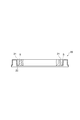
- FIG. 1 It is a figure which shows schematic structure of the cell observation apparatus 1 which concerns on 1st Embodiment of this invention. It is a perspective view which shows the structure of the microplate 20 of FIG. It is side surface sectional drawing which shows the cross-section of the microplate 20 of FIG. It is a figure which shows the variation of the shape of the well formed in the microplate 20 of FIG. It is a figure which shows the structure of the electrode pair 17 in the state in which the electrical stimulation part 16 of FIG. 1 was inserted in the well. It is a figure which shows another structure of the electrode pair 17 in the state in which the electrical stimulation part 16 of FIG. 1 was inserted in the well. It is a figure which shows another structure of the electrode pair 17 in the state in which the electrical stimulation part 16 of FIG.
- FIG. 1 is a configuration diagram schematically showing the cell observation device 1 according to the first embodiment of the present invention.
- FIG. 2 is a perspective view showing an example of the configuration of the microplate 20.
- 3 is a side cross-sectional view showing the cross-sectional structure of the microplate 20 shown in FIG. 2, and
- FIG. 4 is a view showing variations in the shape of the well formed in the microplate 20.
- the cell observation apparatus 1 according to the present embodiment is an apparatus for measuring fluorescence from a sample S placed at a measurement position P while being held by the microplate 20 using a microplate 20 as a sample case.
- the sample S includes predetermined cells.
- the predetermined cells include, for example, cardiomyocytes, muscle cells or nerve cells, skin cells, visual cells, germ cells, hepatocytes, etc. differentiated from stem cells such as iPS (induced Pluripotent Stem) cells and ES (Embryonic Stem) cells. is there.
- the predetermined cell may be a cell stained with a membrane potential sensitive dye, a calcium sensitive dye, or a sodium ion sensitive dye.
- the cell observation device, the electrical stimulation device, and the cell observation method in the present embodiment are generally applicable to light measurement that measures light emitted from a sample, such as phosphorescence or luminescence.
- the configuration of the cell observation device 1 will be described.
- the data acquisition device 10 includes a dark box 15 in which a microplate 20 holding cells to be subjected to fluorescence observation is housed, and a fluorescence of a sample S that is placed inside the dark box 15 and placed at a measurement position P. And a moving image acquisition unit 40 used for measurement. Note that the position controller 30, the imaging controller 32, and the electrical stimulation controller 34 may be installed inside the data acquisition device 10.
- the microplate 20 used as a sample case in the present embodiment is a plate-like member in which a plurality of wells (holding portions) 21 are arranged in a two-dimensional array, as shown in FIGS. Each of the plurality of wells 21 is configured to hold the sample S.
- 8 ⁇ 12 96 circular wells 21 are arranged in a two-dimensional array as the plurality of wells 21.
- the number of wells 21 may be an arbitrary number such as 6, 24, 364 or the like.
- Examples of the opening shape of the well 21 cross-sectional shape of the well 21 include a circular shape, an elliptical shape, and a rectangular shape. As shown in FIG.
- the cross-sectional shape in the depth direction of the bottom of the well 21 is formed in a U shape that is a concave shape. If a microplate having such a concave cross-sectional shape is used, the cells are easy to fit in the bottom of the well 21 when the cells are cultured in the well 21. There is an advantage that it is easy to form.
- the bottom surface 22 of the microplate 20 is made of a material (for example, glass, quartz glass, polyethylene, polypropylene, polystyrene) that can transmit the fluorescence measurement excitation light irradiated to the sample S and the fluorescence emitted from the sample S. Etc.).
- a material for example, glass, quartz glass, polyethylene, polypropylene, polystyrene
- the bottom surface 22 of the microplate 20 only needs to be formed of a material that can transmit light emitted from the sample S to be measured.
- the microplate 20 is placed on a microplate holder (mounting unit) 11 having an opening for fluorescence observation.
- a microplate transport mechanism 12 that transports the microplate 20 and the microplate holder 11 in a predetermined direction (the direction from the right side to the left side in FIG. 1) in the dark box 15 is provided in the dark box 15. is set up.
- a predetermined number (for example, 25) of the pre-measurement microplate 20 holding the sample S is stocked on one side of the dark box 15 which is the carry-in side with respect to the transport direction of the microplate 20 in the transport mechanism 12.
- a loading-side microplate stacker 13 is provided for storage. Further, on the other side of the dark box 15 on the carry-out side with respect to the conveyance direction of the microplate 20, a carry-out microplate stacker 14 for stocking the measured microplate 20 is installed.
- the microplate 20 carried into the dark box 15 from the carry-in microplate stacker 13 is held by the microplate holder 11 and carried by the carrying mechanism 12.
- the microplate 20 is temporarily stopped at the measurement position P, and in this state, necessary light measurement is performed on the sample S held by the microplate 20.
- the microplate 20 is again transported by the transport mechanism 12 and unloaded to the unloading side microplate stacker 14.
- FIG. 1 a specific configuration for carrying in, carrying, and carrying out the microplate 20 is omitted for the carrying mechanism 12 and the stackers 13 and 14.
- an electrical stimulation unit is inserted into the well 21 of the microplate 20 to apply an electric field (electric stimulation) to the sample S.
- Electric stimulation device 16 is installed below the measurement position P.
- a moving image acquisition unit 40 used for detection of fluorescence emitted from the sample S accommodated in the well 21 through the bottom surface 22 of the microplate 20 is installed below the measurement position P.
- the moving image acquisition unit 40 detects a two-dimensional light image representing a two-dimensional light intensity distribution of the microplate 20 including light emitted from the sample S held in the well 21 of the microplate 20, and performs two-dimensional It is a moving image acquisition means for acquiring moving image data of a light image.
- the detected two-dimensional light image may be a light intensity distribution including light emitted from the sample S held in at least one well 21.
- the moving image acquisition unit 40 includes an imaging device 45, a light guide optical system 41, an optical filter unit 42, and an excitation light source 43.
- the imaging device 45 has a two-dimensional pixel structure in which a plurality of pixels are two-dimensionally arranged, and detects a fluorescence image that is a two-dimensional photodetection image by fluorescence emitted from the sample S.
- a camera equipped with an area image sensor such as a highly sensitive CCD image sensor or CMOS image sensor can be used.
- the moving image acquisition unit 40 may be configured by arranging an image intensifying element such as an MCP (microchannel plate), a relay lens, or the like in front of the camera. Note that the moving image acquisition unit 40 may acquire a still image and has a function as an image acquisition unit that acquires a moving image and / or a still image.
- a light guide optical system 41 is installed between the measurement position P where the microplate 20 is arranged and the imaging device 45.
- the light guide optical system 41 is an optical system that guides to the imaging device 45 a two-dimensional light image obtained by viewing the microplate 20 holding the sample S in each of the plurality of wells 21 from the bottom surface 22 side.
- the specific configuration of the light guide optical system 41 is appropriately configured by an optical element capable of realizing necessary functions (for example, a condensing function, an optical image reduction function, etc.) according to the configurations of the microplate 20 and the imaging device 45. Just do it.
- An example of such an optical element is a tapered fiber (see Japanese Patent Application Laid-Open No. 2001-188044).
- the light guide optical system 41 may be configured to use a light irradiation device having a light guide member having unevenness (see Japanese Patent Application Laid-Open Nos. 2010-23097 and 2010-230396).
- an optical filter capable of further arranging and switching the optical filter on the light guide optical path of fluorescence between the light guide optical system 41 and the imaging device 45 as necessary.
- Part 42 is installed. However, such an optical filter unit 42 may be omitted if unnecessary.
- the excitation light source 43 is excitation light supply means for supplying the sample S with excitation light for fluorescence measurement.
- a specific configuration of the excitation light source 43 may be appropriately configured according to the type of the sample S to be subjected to fluorescence measurement, the wavelength of the excitation light irradiated on the sample S, and the like.
- an illumination light source that supplies light and an optical filter unit for selecting and switching the wavelength of the excitation light.
- the excitation light source 43 may be omitted.
- the light guide optical system 41 can guide the two-dimensional light image from the microplate 20 and the sample S to the imaging device 45 and guide the excitation light from the excitation light source 43 to the sample S.
- Such an optical system can be configured by using, for example, a dichroic mirror that transmits fluorescence from the microplate 20 and reflects excitation light from the excitation light source 43.
- the optical paths of fluorescence and excitation light in the light guide optical system 41 are schematically shown by solid lines and broken lines, respectively.
- the microplate 20 used in the cell observation apparatus 1 those having various well 21 shapes can be adopted.
- 4A to 4D show variations of the concave shape of the well 21, each of which is a cross-sectional view along the depth direction of the well 21 in the upper portion and a plane viewed from the depth direction of the well in the lower portion. The figure is shown.
- the well 21 has a U-shaped bottom, a V-shaped bottom, a conical bottom, and a pyramid-shaped bottom. . Even if the microplate 20 having the well 21 having such a shape is used, there is a merit that the localization of the cells is good and the cells are easily formed three-dimensionally in the well 21.
- the electrical stimulation part 16 has a structure fixed to the base part 18 so that a plurality of electrode pairs 17 extending vertically toward the microplate 20 are two-dimensionally arranged. Specifically, the electrode pairs 17 are two-dimensionally arranged corresponding to the two-dimensional array of the plurality of wells 21 of the microplate 20 so as to face the wells 21 of the microplate 20. .
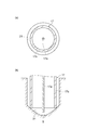
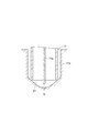
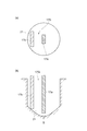
- FIG. 5 shows the structure of the electrode pair 17 in a state where the electrical stimulation unit 16 is inserted into the well 21 of the microplate 20, where (a) is a cross-sectional view along the opening of the well 21, and (b) is the well 21. It is sectional drawing along the depth direction.
- the electrode pair 17 includes a rod-like (for example, columnar) first electrode 17a extending in the depth direction of the well 21 and a tip that is open, and the first electrode 17a is located inside the central axis.
- the second electrode 17b has a cylindrical shape located on the top, and the outer diameter of the second electrode 17b is smaller than the inner diameter of the well 21.
- the electrode pair 17 has a structure in which the tip on the bottom side of the well 21 of the first electrode 17a extends from the tip on the bottom side of the well 21 of the second electrode 17b.
- the cylindrical second electrode 17 b comes into contact with the bottom surface 22 of the well 21 and is positioned.
- the second electrode 17b can easily fit into the U-shaped or conical well 21, and the electrode pair 17 can be easily positioned.
- the first electrode 17a extends beyond the second electrode 17b, the distance between the sample S located on the bottom surface 22 and the tip of the first electrode 17a can be reduced, and the sample S is efficient. Electrical stimulation can be applied.
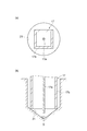
- FIG. 6 shows another structure of the electrode pair 17 in a state where the electrical stimulation unit 16 is inserted into the well 21 of the microplate 20, (a) is a cross-sectional view along the opening of the well 21, and (b) 3 is a cross-sectional view along the depth direction of a well 21.
- the electrode pair 17 includes a rod-like (for example, columnar) first electrode 17a extending in the depth direction of the well 21 and a tip that is open, and the first electrode 17a is located inside the central axis. You may be comprised by the 2nd electrode 17b which has a square cylinder shape located above.
- Such an electrode pair 17 also has a structure in which the tip on the bottom side of the well 21 of the first electrode 17a extends from the tip on the bottom side of the well 21 of the second electrode 17b.
- the second electrode 17 b can easily fit into the pyramid-shaped well 21, and the electrode pair 17 can be easily positioned with respect to the well 21.
- the first electrode 17a extends beyond the second electrode 17b, the distance between the sample S located on the bottom surface 22 and the tip of the first electrode 17a can be reduced, and the sample S is efficient. Electrical stimulation can be applied.
- the shape of the first electrode 17a constituting the electrode pair 17 may be changed to various shapes other than the cylindrical shape.
- 7 and 8 are cross-sectional views along the opening of the well 21 of the electrode pair 17 in a state where the electrical stimulation unit 16 is inserted into the well 21.
- the first electrode 17a may have a prismatic shape or a plate shape.
- either or both of the tips on the bottom side of the well 21 of the first and second electrodes 17a and 17b constituting the electrode pair 17 have a sharp convex shape or a round convex shape. May be.
- FIG. 9 is a cross-sectional view taken along the depth direction of the well 21 of the electrode pair 17 having a convex shape.
- the first electrode 17a having such a shape electrical stimulation can be more efficiently applied to the sample S in the vicinity of the first electrode 17a. Further, according to the second electrode 17b having such a shape, the electrode pair 17 can be easily fitted to the U-shaped well 21 and the pyramid-shaped well 21.
- the first electrode 17a constituting the electrode pair 17 may be covered with an insulator other than the tip portion that applies electrical stimulation to the sample S.
- FIG. 10 is a cross-sectional view along the depth direction of the well 21 of the electrode pair 17 covered with an insulator. As shown in the figure, the first electrode 17 a is covered with an insulator 70 except for the tip on the bottom side of the well 21. According to the first electrode 17a having such a configuration, electrical stimulation can be applied to the sample S more efficiently.
- the insulator 70 can be formed on the first electrode 17a by coating with an insulating material or covering the first electrode 17a with an insulating tube.
- the electrode pair 17 is not limited to one in which the first electrode 17a and the second electrode 17b are each constituted by one member, either one or both may be constituted by a plurality of members.
- the electrical stimulation unit 16 is provided with a moving mechanism 19 that supports the electrode pair 17 via the base unit 18.
- the moving mechanism 19 is a driving mechanism that moves the electrode pair 17 so as to approach or retreat with respect to the microplate 20 (Z direction in FIG. 1).
- the electrode pair 17 is driven to be detached from the well 21 at the end of observation of the sample S.
- the electrode pair 17 can be disposed in the well 21 in a state where the first electrode 17a is disposed closer to the center of the well 21 than the second electrode 17b.
- the moving mechanism 19 may move the electrode pair 17 in a direction along the bottom surface 22 of the microplate 20 (a direction along a plane including the X axis and the Y axis in FIG. 1).
- the moving mechanism 19 can improve the accuracy of adjusting the position so that the first electrode 17a is disposed closer to the center of the well 21 than the second electrode 17b. Further, instead of the moving mechanism 19, a configuration is adopted in which the microplate holder 11 on which the microplate 20 is placed is moved in a direction along the plane including the Z direction in FIG. 1 and the X axis and the Y axis in FIG. 1. May be.
- the position controller (position controller) 30, the imaging controller 32, and the electrical stimulation controller 34 are connected to the data acquisition device 10 having such a configuration.
- the position controller 30 is electrically connected to the moving mechanism 19 and controls the moving mechanism 19 so that the electrode pair 17 is disposed in the well 21 of the microplate 20 at the start of optical measurement of the sample S. Specifically, as shown in FIGS. 5 to 10, when the electrode pair 17 is arranged in the well 21, the position controller 30 has the first electrode 17a in the well 21 rather than the second electrode 17b.
- the position of the electrode pair 17 is controlled so that the electrode pair 17 is put in and out of the well 21 in a state where the electrode pair 17 is arranged near the center of the well.
- the position controller 30 inserts (moves) the electrode pair 17 into the well 21 so that the tip of the second electrode contacts the outside of the center of the bottom surface 22 of the well 21. Control is performed so that the tip of the electrode 17 a is positioned near the center of the bottom surface 22 of the well 21.
- the electrical stimulation controller 34 is electrically connected to the electrical stimulation device 16 and supplies an electrical signal between the first electrode 17a and the second electrode 17b of the electrode pair 17 to the sample S. Apply electrical stimulation such as voltage and current.
- the imaging controller 32 controls excitation light irradiation by the excitation light source 43 and imaging of a two-dimensional fluorescence image on the microplate 20 by the imaging device 45.
- a computer 50 is connected to the position controller 30, the imaging controller 32, and the electrical stimulus controller 34.
- the computer 50 includes a data analysis unit 51 that acquires moving image data including a light detection image acquired by the moving image acquisition unit 40 and performs analysis processing on the moving image data.
- the computer 50 includes a control unit 52 that controls the operation of each unit of the data acquisition device 10 via the position controller 30, the imaging controller 32, and the electrical stimulation controller 34, and the sample in the cell observation device 1. Fluorescence measurement for S is controlled (details will be described later).
- a display device 61 that displays measurement results and the like, and an input device 62 that is used for inputting data, inputting instructions necessary for fluorescence measurement, and the like are connected to the computer 50.
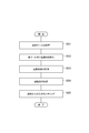
- FIG. 11 is a flowchart showing the operation of the cell observation apparatus 1 during the light measurement of the sample S.
- the microplate 20 to be measured holding the sample S in the microplate stacker 13 is placed on the microplate holder 11. In the state, it is transported to the measurement position P in the dark box 15 by the microplate transport mechanism 12 (step S01). Then, the position of the electrical stimulation unit 16 is controlled by the computer 50 using the moving mechanism 19, whereby the tips of the plurality of electrode pairs 17 are respectively inserted into the corresponding wells 21 of the microplate 20 (step S02). . At this time, the computer 50 controls the position of the electrode pair 17 so that the tip of the second electrode 17 b of the electrode pair 17 contacts the outside of the center of the bottom surface 22 of the microplate 20. As a result, the first electrode 17 a is arranged in a state where the tip thereof is separated from the vicinity of the center of the bottom surface 22 of the well 21 by a predetermined distance.
- the electrical stimulation controller 34 is controlled by the computer 50, whereby an electrical signal is supplied to the electrode pair 17 and electrical stimulation is applied to the sample S in the well 21 of the microplate 20 (step S03).
- the application of electrical stimulation is repeatedly performed at a predetermined cycle (for example, 1 to 10 Hz).
- a predetermined cycle for example, 1 to 10 Hz.
- the imaging controller 32 is controlled by the computer 50 in the state where the application of electrical stimulation is started, irradiation of excitation light by the excitation light source 43 is started (step S04).
- a two-dimensional light image of the microplate 20 including fluorescence emitted from the sample S held in the well 21 is detected by the moving image acquisition unit 40, and moving image data representing the two-dimensional light image is stored in the computer 50. Obtained by.
- the frame rate of the moving image acquisition unit 40 is set to be higher than the frequency of the electric signal. Furthermore, the light intensity in the analysis region set in the region facing the electrode pair 17 of the microplate 20 on the microplate holder 11 by the computer 50 is targeted for the two-dimensional light image included in the acquired moving image data. By analyzing, the analysis information (monitoring result) regarding the sample S is acquired and output to the display device 61 (step S05).
- the analysis information can be obtained by monitoring the fluorescence intensity from the cardiomyocytes stained with a calcium ion sensitive dye in time series. At that time, by applying electrical stimulation to the myocardial cells, the intensity and cycle of pulsation can be made uniform, so that quantitative evaluation of the reagent becomes possible. Thereby, the side effect with respect to the cardiomyocyte of a reagent can be evaluated.
- a membrane potential sensitive fluorescent dye is applied to the cells in the sample S, when an electrical stimulus is applied, a change in membrane potential accompanying the opening and closing of the ion channel of the cells is observed as a change in fluorescence intensity.
- the membrane potential can be controlled by applying electrical stimulation to the sample S.
- the amplitude, rate of change, peak period, number of peaks, peak time, rise time, fall time, peak fluctuation range, etc. are calculated as evaluation values in the analysis area. It is conceivable to do this
- the electrode pair 17 including the first electrode 17 a and the second electrode 17 b is disposed in the well 21 provided in the microplate 20.
- electrical stimulation can be applied to the sample S containing cells by the electrode pair 17.
- the tip of the first electrode 17a arranged near the center in the well 21 extends beyond the tip of the second electrode 17b arranged outside in the well 21, the well 21 is recessed. Even in the case where the bottom portion has a shape, the tip of the first electrode 17a can be easily brought close to the sample S including the cells held on the bottom portion.
- electrical stimulation can be appropriately given to the sample S from the electrode pair 17 only by using a simple position control mechanism, and an appropriate evaluation result regarding the sample S can be obtained.
- the shape of the electrode pair 17 can easily fit into the concave inner shape of the well 21.
- the distance between the sample S held at the bottom and the first electrode 17a can be reduced.
- electrical stimulation can be efficiently applied to the sample S.
- the first electrode 17a is columnar, the distance between the sample S held at the bottom of the well 21 and the first electrode 17a can be easily reduced. As a result, electrical stimulation can be efficiently applied to the sample S.
- FIG. 12 is a configuration diagram schematically showing a cell observation device 1A according to the second embodiment of the present invention.
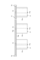
- the difference between the cell observation apparatus 1A according to the first embodiment of the cell observation apparatus 1A shown in the figure is that the position adjustment mechanism 71 is provided in the electrical stimulation unit 16A.
- the configuration is the same as in the first embodiment.
- the position adjusting mechanism 71 is fixed to the base portion 18 of the electrical stimulation unit 16A and supports the electrode pair 17 so that the first electrode 17a and the second electrode 17b can move independently.
- the position adjusting mechanism 71 includes a long first support 72a that supports the base ends of the first electrodes 17a of the plurality of electrode pairs 17 on the base portion 18 side, and a plurality of first supports 72a.
- the distance between the long second support 72b that supports the base end of the second electrode 17b on the base portion 18 side of the electrode pair 17 and the first and second supports 72a and 72b can be adjusted.
- the first and second support bodies 72a and 72b are configured to be adjusted.
- the second support 72b is provided with a through hole 74 through which the first electrode 17a passes.
- the first electrode 17a of the plurality of electrode pairs 17 and the second electrode 17b of the plurality of electrode pairs 17 are respectively moved in the direction of the central axis (first first electrode 17b).
- the electrode 17a can be moved independently along the longitudinal direction of the electrode 17a.
- the relative position of the tip of the first electrode 17a with respect to the tip of the second electrode 17b can be adjusted simultaneously.
- the positions of the tips of the plurality of electrode pairs 17 can be adjusted simultaneously and easily. can do.
- the positions of the tips of the first electrodes 17a can be adjusted so that the tips of the first electrodes 17a extend beyond the tips of the second electrodes 17b.
- the tip of the first electrode 17 a and the tip of the second electrode 17 b are the same height when viewed from the base portion 18. It is also possible to adjust so that the tip of the second electrode 17b extends beyond the tip of the first electrode 17a.
- the position adjustment mechanism 71 may fix the position of the second support 72b, adjust the distance from the base portion 18 of the first support 72a, or may adjust the position of the first support 72a.
- the distance from the base portion 18 of the second support 72b may be adjusted, or the distance from the base portion 18 of both the first and second supports 72a and 72b may be adjusted. . In either case, the relative position between the tip of the first electrode 17a and the tip of the second electrode 17b can be adjusted.
- the position adjustment mechanism 71 may be configured by an electric drive unit using a piezo actuator, a stepping motor, or the like, may be configured by a manual mechanism capable of manual position adjustment, or has a structure using a screw structure. May be.
- the adjustment unit 73 is electrically connected to the position control controller 30, and the first and second signals are controlled by a control signal from the position control controller 30.
- the positions of the supports 72a and 72b are configured to be electronically controllable.
- the position of the electrode pair 17 may be controllable as follows. First, information on the shape of the well 21 of the microplate 20 used for observation by the input device 62 (for example, information indicating whether it is a flat bottom or a U-shaped bottom, depth information on the U-shaped bottom), or the second Information (width or height information) related to the tip position of the first electrode 17a with respect to the tip position of the electrode 17b is input. Then, the relative position of the tip of the first electrode 17a with respect to the tip of the second electrode 17b is determined by the position controller 30, and the first support 72a and the second support are in a relationship of the relative position. The interval between the bodies 72b is automatically adjusted. In this way, the position adjustment mechanism 71 can adjust the position of the tip of the first electrode 17a with respect to the tip of the second electrode 17b.
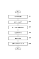
- FIG. 16 is a flowchart showing an operation at the time of light measurement of the sample S of the cell observation device 1A.
- the position controller 30 controls the tip of the first electrode 17 a in the plurality of electrode pairs 17.
- the positional relationship with the tip of the second electrode 17b is automatically adjusted (step S21).
- the microplate 20 to be measured holding the sample S in the microplate stacker 13 is transported to the measurement position P in the dark box 15 by the microplate transport mechanism 12 while being placed on the microplate holder 11.
- the position of the electrical stimulation unit 16 is controlled by the computer 50 using the moving mechanism 19, whereby the tips of the plurality of electrode pairs 17 are inserted into the corresponding wells 21 of the microplate 20 (step S23). .
- the computer 50 controls the position of the electrode pair 17 so that the tip of the second electrode 17 b of the electrode pair 17 contacts the outside of the center of the bottom surface 22 of the microplate 20.
- the first electrode 17 a is arranged in a state where the tip thereof is separated from the vicinity of the center of the bottom surface 22 of the well 21 by a predetermined distance.
- the electrical stimulation controller 34 is controlled by the computer 50, whereby an electrical signal is supplied to the electrode pair 17 and electrical stimulation is applied to the sample S in the well 21 of the microplate 20 (step S24).
- the application of electrical stimulation is repeatedly performed at a predetermined cycle (for example, 1 to 10 Hz).
- the imaging controller 32 is controlled by the computer 50, so that irradiation of excitation light by the excitation light source 43 is started (step S25).
- a two-dimensional light image of the microplate 20 including fluorescence emitted from the sample S held in the well 21 is detected by the moving image acquisition unit 40, and moving image data representing the two-dimensional light image is stored in the computer 50. Obtained by.
- the frame rate of the moving image acquisition unit 40 is set to be higher than the frequency of the electric signal. Furthermore, the light intensity in the analysis region set in the region facing the electrode pair 17 of the microplate 20 on the microplate holder 11 by the computer 50 is targeted for the two-dimensional light image included in the acquired moving image data. By analyzing, the analysis information (monitoring result) regarding the sample S is acquired and output to the display device 61 (step S26).
- the position adjustment processing of the electrode pair 17 in step S21 may be performed when the electrode pair 17 in step S22 is inserted into the well 21. Further, the process of step S21 may be executed after the process of inserting the electrode pair 17 of step S23 into the well 21 and before step S24 of starting the application of electrical stimulation, and from the sample of step S26. Based on the light monitoring, the reaction of the sample S is evaluated, the position adjustment process of the electrode pair 17 in step S21 is performed again, the electrical stimulation application process in step 24, the excitation light irradiation process in step 25, and the optical monitoring in step S26. Processing cycles may be performed. This cycle may be repeated multiple times. By these, the intensity
- the electrode pair 17 including the first electrode 17a and the second electrode 17b is disposed in the well 21 provided in the microplate 20.
- electrical stimulation can be applied to the sample S containing cells by the electrode pair 17.
- the relative position of the tip of the first electrode 17a with respect to the tip of the second electrode 17b is adjustable, even if the well 21 has a concave bottom, The tip of the first electrode 17a can be easily brought close to the sample S containing the cells held on the bottom.
- the tip of the first electrode 17a can be appropriately brought close to the sample S in accordance with the shape.
- FIG. 17 shows an example of measurement results when cardiomyocytes differentiated from iPS cells were observed using a microplate 20 having a U-shaped cross-sectional shape in the depth direction of the bottom of the well 21.
- the cardiomyocytes are stained with a Ca 2+ sensitive dye.
- FIG. 17 (a) shows a temporal change in fluorescence intensity associated with a change in intracellular Ca 2+ concentration by applying 1.0 Hz electrical stimulation using an electrical stimulation apparatus having a conventional coaxial cable-shaped electrode. The result of having measured is shown.
- FIG. 17B when the electrode pair 17 is disposed in the U-shaped well 21, the first electrode 17a disposed from the center of the well 21 extends more than the second electrode 17b.
- the first electrode 17a arranged from the center is more than the second electrode 17b. Since it extends, it can be seen that the distance between the sample S located on the bottom surface of the well 21 and the tip of the first electrode 17a can be reduced, and electrical stimulation can be efficiently applied to the sample S.
- the structure of the electrode pair 17 of the electrical stimulation unit 16 of the cell observation device 1, 1A is not limited to the cylindrical shape, and various shapes can be adopted.
- 18A and 18B show the configuration of the electrode pair 17A according to a modification of the present invention in a state where it is inserted into the well 21 of the microplate 20, wherein FIG. 18A is a cross-sectional view along the opening of the well 21, 3 is a cross-sectional view along the depth direction of a well 21.
- a rod-shaped electrode (for example, a cylindrical electrode) may be used.
- FIG. 19 shows a configuration of the electrode pair 17B according to another modification of the present invention inserted into the well 21 of the microplate 20, wherein (a) is a cross-sectional view taken along the opening of the well 21, FIG. 4B is a cross-sectional view along the depth direction of the well 21.
- the second electrode 17b is composed of two parallel rod-like electrodes (for example, cylindrical electrodes), and the first electrode 17a is the center between the two plate-like electrodes.
- the electrode may be a rod-shaped electrode (for example, a cylindrical electrode) disposed along them.
- the first electrode 17a may be prismatic, plate-shaped, or covered with an insulator.
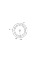
- FIG. 20 is a cross-sectional view along the opening of the well 21 in a state where the electrode pair 17C is inserted into the well 21 of the microplate 20 according to another modification of the present invention.
- the second electrode 17b may be composed of three or more.
- the electrode pair 17C includes three rod-like second electrodes 17b arranged in parallel and a rod-like first electrode 17a arranged between the second electrodes 17b.
- the first electrode 17a is disposed at the center of a region surrounded by a boundary line L1 that connects the centers of the sections along the opening of the well 21 of the second electrode 17b.
- FIG. 21 shows a configuration of the electrode pair 17D according to another modification of the present invention inserted into the well 21 of the microplate 20, wherein (a) is a cross-sectional view along the opening of the well 21, FIG. 4B is a cross-sectional view along the depth direction of the well 21.
- the second electrode 17b is composed of one rod-like electrode (columnar or prismatic electrode), and the first electrode 17a is close to the center of the well 21 and parallel to the second electrode 17b. It may be composed of rod-shaped electrodes (columnar or prismatic electrodes) disposed on the surface.
- FIG. 22 shows a configuration of the electrode pair 17E according to another modified example of the present invention inserted into the well 21 of the microplate 20, wherein (a) is a cross-sectional view taken along the opening of the well 21, FIG. 4B is a cross-sectional view along the depth direction of the well 21.
- the second electrode 17b is composed of one plate-like electrode, and the first electrode 17a is arranged near the center of the well 21 in parallel with the second electrode 17b.
- Columnar or prismatic electrodes Such electrode pairs 17D and 17E are employed when the number of wells 21 provided on the microplate 20 is 100 or more, such as 364, and the width of the well 21 is narrow. In such a case, if the electrode pair 17D, 17E is used, it can be easily inserted into the well 21 and the tip of the first electrode 17a can be easily arranged near the center of the bottom surface of the well 21.
- the electrode pairs 17A to 17E employed in the cell observation device 1 have a structure in which the tip of the first electrode 17a extends beyond the tip of the second electrode 17b. Further, in the electrode pairs 17, 17A to 17E, when the first electrode 17a is configured by a plate electrode, the width of the tip of the first electrode 17a is smaller than the width of the tip of the second electrode 17b. It is desirable to do.
- FIGS. 23 and 24 show the configuration of the electrode pair 17F and 17G according to the modification of the present invention in such a case in a state where they are inserted into the well 21 of the microplate 20, respectively.
- FIG. 4B is a cross-sectional view taken along the depth direction of the well 21.
- the electrode pair 17G is a plate-like electrode, and includes a first electrode 17a and a second electrode 17b, and the overall width of the first electrode 17a is smaller than the width of the second electrode 17b.
- the electrode pair 17F is configured such that the second electrode 17b is configured by a rod-shaped electrode, the first electrode 17a is configured by a plate-shaped electrode, and the width of the first electrode 17a is narrowed toward the tip.
- a convex portion having a smaller width than the tip of the second electrode 17b is formed at the tip of the first electrode 17a. According to the electrode pair 17F and 17G having such a configuration, the distance between the sample S held on the concave bottom surface 22 of the well 21 and the first electrode 17a can be easily reduced.
- the second electrode may have a cylindrical shape, and the first electrode may be disposed inside the second electrode.
- the second electrode may include a plurality of electrode members, and the first electrode may be disposed between the plurality of electrode members. If such an electrode pair is provided, the electrode pair can be easily reduced in size, and electrical stimulation can be appropriately applied to the sample in the holding unit.
- the first electrode may have a column shape. In this case, the distance between the sample held at the bottom of the holding part and the first electrode can be easily reduced. As a result, electrical stimulation can be efficiently applied to the sample.
- the width of the tip of the first electrode may be smaller than the width of the tip of the second electrode.
- the present invention uses a cell observation apparatus, an electric stimulation apparatus, and a cell observation method for observing a reaction associated with electrical stimulation on a sample containing cells, and is suitable for cells arranged in a holding unit. It is possible to give electrical stimulation.
- Electrode pair 1, 1A ... Cell observation device, 10 ... Data acquisition device, 11 ... Microplate holder (mounting unit), 12 ... Microplate transport mechanism, 16, 16A ... Electric stimulation unit (electricity) Stimulation device), 17a ... first electrode, 17b ... second electrode, 19 ... moving mechanism, 20 ... microplate (sample case), 21 ... well (holding portion), 22 ... bottom surface, 30 ... position control controller ( Position control unit), 32 ... Imaging controller, 34 ... Electrical stimulation controller, 40 ... Moving image acquisition unit, 50 ... Computer, 51 ... Data analysis unit, 52 ... Control unit, 71 ... Position adjustment mechanism (position adjustment unit) 72a, 72b ... support, 73 ... adjusting part, S ... sample.
Landscapes
- Health & Medical Sciences (AREA)
- Life Sciences & Earth Sciences (AREA)
- Engineering & Computer Science (AREA)
- Chemical & Material Sciences (AREA)
- Biomedical Technology (AREA)
- Physics & Mathematics (AREA)
- General Health & Medical Sciences (AREA)
- Biochemistry (AREA)
- Analytical Chemistry (AREA)
- Organic Chemistry (AREA)
- Zoology (AREA)
- Bioinformatics & Cheminformatics (AREA)
- Wood Science & Technology (AREA)
- Pathology (AREA)
- General Physics & Mathematics (AREA)
- Immunology (AREA)
- Genetics & Genomics (AREA)
- Molecular Biology (AREA)
- Biotechnology (AREA)
- Hematology (AREA)
- Biophysics (AREA)
- Food Science & Technology (AREA)
- Urology & Nephrology (AREA)
- Medicinal Chemistry (AREA)
- General Engineering & Computer Science (AREA)
- Microbiology (AREA)
- Sustainable Development (AREA)
- Nuclear Medicine, Radiotherapy & Molecular Imaging (AREA)
- Optics & Photonics (AREA)
- Cell Biology (AREA)
- Electromagnetism (AREA)
- Chemical Kinetics & Catalysis (AREA)
- Electrochemistry (AREA)
- Investigating, Analyzing Materials By Fluorescence Or Luminescence (AREA)
- Apparatus Associated With Microorganisms And Enzymes (AREA)
- Measuring Or Testing Involving Enzymes Or Micro-Organisms (AREA)
- Investigating Or Analysing Biological Materials (AREA)
Abstract
Priority Applications (6)
| Application Number | Priority Date | Filing Date | Title |
|---|---|---|---|
| EP14878675.9A EP3095853B1 (fr) | 2014-01-16 | 2014-11-12 | Dispositif d'observation de cellules, dispositif d'électrostimulation et procédé d'observation de cellules |
| JP2015557720A JP6499086B2 (ja) | 2014-01-16 | 2014-11-12 | 細胞観察装置、電気刺激装置、及び細胞観察方法 |
| US15/110,678 US10415010B2 (en) | 2014-01-16 | 2014-11-12 | Cell observation device, electrostimulation device, and cell observation method |
| EP18209767.5A EP3495468B1 (fr) | 2014-01-16 | 2014-11-12 | Dispositif d'observation de cellules, dispositif d'électrostimulation et procédé d'observation de cellules |
| US16/527,423 US11248202B2 (en) | 2014-01-16 | 2019-07-31 | Cell observation device, electrostimulation device, and cell observation method |
| US17/565,929 US12595456B2 (en) | 2014-01-16 | 2021-12-30 | Cell observation device, electrostimulation device, and cell observation method |
Applications Claiming Priority (2)
| Application Number | Priority Date | Filing Date | Title |
|---|---|---|---|
| JP2014-005990 | 2014-01-16 | ||
| JP2014005990 | 2014-01-16 |
Related Child Applications (2)
| Application Number | Title | Priority Date | Filing Date |
|---|---|---|---|
| US15/110,678 A-371-Of-International US10415010B2 (en) | 2014-01-16 | 2014-11-12 | Cell observation device, electrostimulation device, and cell observation method |
| US16/527,423 Continuation US11248202B2 (en) | 2014-01-16 | 2019-07-31 | Cell observation device, electrostimulation device, and cell observation method |
Publications (1)
| Publication Number | Publication Date |
|---|---|
| WO2015107761A1 true WO2015107761A1 (fr) | 2015-07-23 |
Family
ID=53542665
Family Applications (1)
| Application Number | Title | Priority Date | Filing Date |
|---|---|---|---|
| PCT/JP2014/079964 Ceased WO2015107761A1 (fr) | 2014-01-16 | 2014-11-12 | Dispositif d'observation de cellules, dispositif d'électrostimulation et procédé d'observation de cellules |
Country Status (5)
| Country | Link |
|---|---|
| US (3) | US10415010B2 (fr) |
| EP (2) | EP3095853B1 (fr) |
| JP (2) | JP6499086B2 (fr) |
| ES (1) | ES2915663T3 (fr) |
| WO (1) | WO2015107761A1 (fr) |
Cited By (2)
| Publication number | Priority date | Publication date | Assignee | Title |
|---|---|---|---|---|
| JP2018087770A (ja) * | 2016-11-29 | 2018-06-07 | 株式会社リコー | 液滴分注装置、液滴分注方法、及び被着対象物 |
| PL443991A1 (pl) * | 2023-03-07 | 2024-09-09 | Akademia Górniczo-Hutnicza im. Stanisława Staszica w Krakowie | System do elektrostymulacji komórek w warunkach in vitro |
Families Citing this family (1)
| Publication number | Priority date | Publication date | Assignee | Title |
|---|---|---|---|---|
| WO2018134733A1 (fr) * | 2017-01-19 | 2018-07-26 | Moshe Giladi | Système de visualisation de cultures cellulaires sous microscope pendant l'application de champs ttfields |
Citations (10)
| Publication number | Priority date | Publication date | Assignee | Title |
|---|---|---|---|---|
| JPS63276478A (ja) * | 1987-05-06 | 1988-11-14 | Shimadzu Corp | 細胞電気刺激チャンバ |
| JP2001188044A (ja) | 1999-12-28 | 2001-07-10 | Hamamatsu Photonics Kk | 発光測定装置、蛍光測定装置、発光測定方法及び蛍光測定方法 |
| JP2004147517A (ja) * | 2002-10-29 | 2004-05-27 | Hitachi Ltd | 遺伝子導入装置 |
| JP2005514909A (ja) | 2001-07-12 | 2005-05-26 | メルク エンド カムパニー インコーポレーテッド | 真核生物細胞の電場による刺激 |
| JP2005204624A (ja) * | 2004-01-26 | 2005-08-04 | Hitachi Ltd | 細胞アッセイ用針状体及び高精度細胞アッセイシステム |
| JP2005261323A (ja) * | 2004-03-19 | 2005-09-29 | National Institute Of Advanced Industrial & Technology | エレクトロポレーションによる遺伝子導入法 |
| JP2010230396A (ja) | 2009-03-26 | 2010-10-14 | Hamamatsu Photonics Kk | 光照射装置及び光測定装置 |
| JP2010230397A (ja) | 2009-03-26 | 2010-10-14 | Hamamatsu Photonics Kk | 光照射装置及び光測定装置 |
| JP2012501646A (ja) * | 2008-09-04 | 2012-01-26 | ガレニア コーポレーション | シナプス小胞サイクリングアッセイおよびシステム |
| JP2012110327A (ja) | 2000-07-10 | 2012-06-14 | Vertex Pharmaceuticals (San Diego) Llc | イオンチャネルアッセイ法 |
Family Cites Families (18)
| Publication number | Priority date | Publication date | Assignee | Title |
|---|---|---|---|---|
| US3065156A (en) * | 1961-08-29 | 1962-11-20 | Organon | Electrolytic ph regulator |
| DE2903246C2 (de) * | 1979-01-29 | 1984-09-06 | Bodenseewerk Perkin-Elmer & Co GmbH, 7770 Überlingen | Verfahren und Vorrichtung zur Anreicherung von in einer Lösung enthaltenen Bestandteilen durch elektrolytische Abscheidung aus der Lösung und zur analytischen Bestimmung der abgeschiedenen Bestandteile durch flammenlose Atomabsorptions-Spektroskopie |
| JPH09196936A (ja) | 1996-01-12 | 1997-07-31 | Bunshi Bio Photonics Kenkyusho:Kk | 光学プローブ顕微鏡装置 |
| CA2258279A1 (fr) * | 1996-06-27 | 1997-12-31 | Peter J. Dehlinger | Procede et dispositif de criblage a haut rendement |
| US7615356B2 (en) | 2000-07-10 | 2009-11-10 | Vertex Pharmaceuticals (San Diego) Llc | Ion channel assay methods |
| US7148059B1 (en) | 2002-02-22 | 2006-12-12 | Ionoptix Corporation | Myocyte culture pacing apparatus |
| AU2003228950A1 (en) * | 2002-05-08 | 2003-11-11 | Scion Pharmaceuticals, Inc. | Oocyte recording chamber |
| US20060199168A1 (en) * | 2002-05-31 | 2006-09-07 | Wills Ivan N | Cell recovery |
| JP4220756B2 (ja) * | 2002-10-28 | 2009-02-04 | 極東製薬工業株式会社 | 培養器、培養器の製造方法及び培養方法 |
| JPWO2004092363A1 (ja) | 2003-04-11 | 2006-07-06 | 独立行政法人理化学研究所 | 細胞の電気刺激方法 |
| US20040210036A1 (en) * | 2003-04-15 | 2004-10-21 | Nanogen, Inc. | Peptide substrate libraries |
| JP2005151807A (ja) * | 2003-11-20 | 2005-06-16 | Olympus Corp | 導入物質の保持方法及び保持装置 |
| US20070004025A1 (en) * | 2005-06-30 | 2007-01-04 | Junne-Jih Chen | Replaceable annular electrode for transgenic |
| JP2009189281A (ja) * | 2008-02-13 | 2009-08-27 | Olympus Corp | 細胞処理装置 |
| JP5614928B2 (ja) * | 2008-12-05 | 2014-10-29 | 国立大学法人 東京医科歯科大学 | 心筋毒性検査装置、心筋毒性検査チップおよび心筋毒性検査方法 |
| JP2011188830A (ja) * | 2010-03-16 | 2011-09-29 | Hioki Ee Corp | 培養容器 |
| US9772322B2 (en) * | 2012-10-25 | 2017-09-26 | Hamamatsu Photonics K.K. | Cell observation device, and cell observation method |
| EP2913390B1 (fr) * | 2012-10-25 | 2020-12-09 | Hamamatsu Photonics K.K. | Dispositif de stimulation électrique, dispositif d'observation cellulaire et procédé d'observation cellulaire |
-
2014
- 2014-11-12 EP EP14878675.9A patent/EP3095853B1/fr active Active
- 2014-11-12 WO PCT/JP2014/079964 patent/WO2015107761A1/fr not_active Ceased
- 2014-11-12 EP EP18209767.5A patent/EP3495468B1/fr active Active
- 2014-11-12 JP JP2015557720A patent/JP6499086B2/ja active Active
- 2014-11-12 ES ES18209767T patent/ES2915663T3/es active Active
- 2014-11-12 US US15/110,678 patent/US10415010B2/en active Active
-
2019
- 2019-03-14 JP JP2019047197A patent/JP6735378B2/ja active Active
- 2019-07-31 US US16/527,423 patent/US11248202B2/en active Active
-
2021
- 2021-12-30 US US17/565,929 patent/US12595456B2/en active Active
Patent Citations (10)
| Publication number | Priority date | Publication date | Assignee | Title |
|---|---|---|---|---|
| JPS63276478A (ja) * | 1987-05-06 | 1988-11-14 | Shimadzu Corp | 細胞電気刺激チャンバ |
| JP2001188044A (ja) | 1999-12-28 | 2001-07-10 | Hamamatsu Photonics Kk | 発光測定装置、蛍光測定装置、発光測定方法及び蛍光測定方法 |
| JP2012110327A (ja) | 2000-07-10 | 2012-06-14 | Vertex Pharmaceuticals (San Diego) Llc | イオンチャネルアッセイ法 |
| JP2005514909A (ja) | 2001-07-12 | 2005-05-26 | メルク エンド カムパニー インコーポレーテッド | 真核生物細胞の電場による刺激 |
| JP2004147517A (ja) * | 2002-10-29 | 2004-05-27 | Hitachi Ltd | 遺伝子導入装置 |
| JP2005204624A (ja) * | 2004-01-26 | 2005-08-04 | Hitachi Ltd | 細胞アッセイ用針状体及び高精度細胞アッセイシステム |
| JP2005261323A (ja) * | 2004-03-19 | 2005-09-29 | National Institute Of Advanced Industrial & Technology | エレクトロポレーションによる遺伝子導入法 |
| JP2012501646A (ja) * | 2008-09-04 | 2012-01-26 | ガレニア コーポレーション | シナプス小胞サイクリングアッセイおよびシステム |
| JP2010230396A (ja) | 2009-03-26 | 2010-10-14 | Hamamatsu Photonics Kk | 光照射装置及び光測定装置 |
| JP2010230397A (ja) | 2009-03-26 | 2010-10-14 | Hamamatsu Photonics Kk | 光照射装置及び光測定装置 |
Non-Patent Citations (1)
| Title |
|---|
| See also references of EP3095853A4 |
Cited By (2)
| Publication number | Priority date | Publication date | Assignee | Title |
|---|---|---|---|---|
| JP2018087770A (ja) * | 2016-11-29 | 2018-06-07 | 株式会社リコー | 液滴分注装置、液滴分注方法、及び被着対象物 |
| PL443991A1 (pl) * | 2023-03-07 | 2024-09-09 | Akademia Górniczo-Hutnicza im. Stanisława Staszica w Krakowie | System do elektrostymulacji komórek w warunkach in vitro |
Also Published As
| Publication number | Publication date |
|---|---|
| EP3095853A1 (fr) | 2016-11-23 |
| JP6735378B2 (ja) | 2020-08-05 |
| US11248202B2 (en) | 2022-02-15 |
| EP3495468A1 (fr) | 2019-06-12 |
| US20160326480A1 (en) | 2016-11-10 |
| ES2915663T3 (es) | 2022-06-24 |
| US12595456B2 (en) | 2026-04-07 |
| EP3095853A4 (fr) | 2017-11-08 |
| EP3495468B1 (fr) | 2022-05-04 |
| US10415010B2 (en) | 2019-09-17 |
| US20190352593A1 (en) | 2019-11-21 |
| US20220119756A1 (en) | 2022-04-21 |
| EP3095853B1 (fr) | 2019-01-30 |
| JP6499086B2 (ja) | 2019-04-10 |
| JPWO2015107761A1 (ja) | 2017-03-23 |
| JP2019092524A (ja) | 2019-06-20 |
Similar Documents
| Publication | Publication Date | Title |
|---|---|---|
| JP6655125B2 (ja) | 細胞観察装置及び細胞観察方法 | |
| US12595456B2 (en) | Cell observation device, electrostimulation device, and cell observation method | |
| CN108474736A (zh) | 用于光遗传学成像的系统和方法 | |
| JP6190420B2 (ja) | 細胞観察装置及び細胞観察方法 | |
| JP6370544B2 (ja) | 細胞観察装置及び細胞観察方法 | |
| Balena et al. | Fabrication of nonplanar tapered fibers to integrate optical and electrical signals for neural interfaces in vivo | |
| US8886278B2 (en) | Optical stimulus probe with reflecting surface | |
| US20140066836A1 (en) | Electroporation devices | |
| JP2009136261A (ja) | チップ駆動装置 | |
| Janiak et al. | Divergent excitation two photon microscopy for 3D random access mesoscale imaging at single cell resolution | |
| JP4926929B2 (ja) | チップ駆動装置 | |
| JP2026060865A (ja) | 測定装置及び培養システム | |
| JP2009153499A (ja) | チップ駆動装置及びカンチレバーチップ | |
| KR101595930B1 (ko) | 다기능 엘이디 일루미네이터 | |
| Vanzetta et al. | Functional imaging using two-photon microscopy in living tissue | |
| JP2009136263A (ja) | チップ駆動装置及びチップ駆動方法 |
Legal Events
| Date | Code | Title | Description |
|---|---|---|---|
| 121 | Ep: the epo has been informed by wipo that ep was designated in this application |
Ref document number: 14878675 Country of ref document: EP Kind code of ref document: A1 |
|
| ENP | Entry into the national phase |
Ref document number: 2015557720 Country of ref document: JP Kind code of ref document: A |
|
| WWE | Wipo information: entry into national phase |
Ref document number: 15110678 Country of ref document: US |
|
| REEP | Request for entry into the european phase |
Ref document number: 2014878675 Country of ref document: EP |
|
| WWE | Wipo information: entry into national phase |
Ref document number: 2014878675 Country of ref document: EP |
|
| NENP | Non-entry into the national phase |
Ref country code: DE |