WO2015108199A1 - Appareil de montage - Google Patents
Appareil de montage Download PDFInfo
- Publication number
- WO2015108199A1 WO2015108199A1 PCT/JP2015/051376 JP2015051376W WO2015108199A1 WO 2015108199 A1 WO2015108199 A1 WO 2015108199A1 JP 2015051376 W JP2015051376 W JP 2015051376W WO 2015108199 A1 WO2015108199 A1 WO 2015108199A1
- Authority
- WO
- WIPO (PCT)
- Prior art keywords
- holding member
- holding members
- holding
- workpiece
- horizontal
- Prior art date
- Legal status (The legal status is an assumption and is not a legal conclusion. Google has not performed a legal analysis and makes no representation as to the accuracy of the status listed.)
- Ceased
Links
Images







Classifications
-
- B—PERFORMING OPERATIONS; TRANSPORTING
- B23—MACHINE TOOLS; METAL-WORKING NOT OTHERWISE PROVIDED FOR
- B23Q—DETAILS, COMPONENTS, OR ACCESSORIES FOR MACHINE TOOLS, e.g. ARRANGEMENTS FOR COPYING OR CONTROLLING; MACHINE TOOLS IN GENERAL CHARACTERISED BY THE CONSTRUCTION OF PARTICULAR DETAILS OR COMPONENTS; COMBINATIONS OR ASSOCIATIONS OF METAL-WORKING MACHINES, NOT DIRECTED TO A PARTICULAR RESULT
- B23Q1/00—Members which are comprised in the general build-up of a form of machine, particularly relatively large fixed members
- B23Q1/03—Stationary work or tool supports
- B23Q1/035—Stationary work or tool supports with an array of longitudinally movable rods defining a reconfigurable support surface
-
- B—PERFORMING OPERATIONS; TRANSPORTING
- B23—MACHINE TOOLS; METAL-WORKING NOT OTHERWISE PROVIDED FOR
- B23Q—DETAILS, COMPONENTS, OR ACCESSORIES FOR MACHINE TOOLS, e.g. ARRANGEMENTS FOR COPYING OR CONTROLLING; MACHINE TOOLS IN GENERAL CHARACTERISED BY THE CONSTRUCTION OF PARTICULAR DETAILS OR COMPONENTS; COMBINATIONS OR ASSOCIATIONS OF METAL-WORKING MACHINES, NOT DIRECTED TO A PARTICULAR RESULT
- B23Q1/00—Members which are comprised in the general build-up of a form of machine, particularly relatively large fixed members
- B23Q1/03—Stationary work or tool supports
- B23Q1/032—Stationary work or tool supports characterised by properties of the support surface
-
- B—PERFORMING OPERATIONS; TRANSPORTING
- B23—MACHINE TOOLS; METAL-WORKING NOT OTHERWISE PROVIDED FOR
- B23Q—DETAILS, COMPONENTS, OR ACCESSORIES FOR MACHINE TOOLS, e.g. ARRANGEMENTS FOR COPYING OR CONTROLLING; MACHINE TOOLS IN GENERAL CHARACTERISED BY THE CONSTRUCTION OF PARTICULAR DETAILS OR COMPONENTS; COMBINATIONS OR ASSOCIATIONS OF METAL-WORKING MACHINES, NOT DIRECTED TO A PARTICULAR RESULT
- B23Q3/00—Devices holding, supporting, or positioning work or tools, of a kind normally removable from the machine
- B23Q3/02—Devices holding, supporting, or positioning work or tools, of a kind normally removable from the machine for mounting on a work-table, tool-slide, or analogous part
- B23Q3/06—Work-clamping means
- B23Q3/062—Work-clamping means adapted for holding workpieces having a special form or being made from a special material
Definitions
- the present invention relates to a technique for holding objects to be processed having various shapes.
- Patent Document 1 describes a technique in which a workpiece placement portion including tip points of a plurality of workpiece support pins urged by a coil spring is deformed according to the shape of the workpiece, and the shape is held by a clamp fitting. Has been.
- an object of the present invention is to hold an object to be processed having various shapes so as to be easily processed.
- the present invention is configured by selecting one or more first holding members, each of which is selected from a plurality of holding members supported so as to be movable in the vertical direction, and on which an object to be processed is placed;
- the one or more second holding members selected from a plurality of holding members and receiving the horizontal force from the object being processed to hold the object, and the one or more second holding members include the object And a control unit that moves the control device in the up and down direction to a position for holding the tool.
- the control unit may include a first movement mechanism that moves the one or more holding members in the vertical direction and a second movement mechanism that moves the first movement mechanism in the horizontal direction. Further, the plurality of holding members are arranged two-dimensionally, and when the one or more holding members belonging to one row move in the vertical direction, the control unit is configured to hold the holding members belonging to another row. You may restrict
- each of the plurality of holding members may have an attachment portion for attaching a member for holding the object from above.
- the information processing apparatus further includes an acquisition unit configured to acquire information indicating a position in the vertical direction for each of the one or more second holding members corresponding to the shape of the object, and the control unit is configured to perform the operation based on the information. You may move the above 2nd holding member.
- Each of the plurality of holding members includes a first member having a contact portion that contacts the object and a second member that supports the first member from below, and the one or more second holding members
- the position of the contact portion in the horizontal direction relative to the second member may be on the object side.
- the horizontal position of the contact portion may be changeable.
- the contact portion may have a rounded shape or may have elasticity.
- objects to be processed having various shapes can be held so as to be easily processed.
- the three axes X, Y, and Z that are orthogonal to each other represent the direction, the direction in which the arrow of each axis faces is the positive direction, and the opposite direction is the negative direction.
- the Z-axis direction is also referred to as the vertical direction (vertical direction)
- the direction orthogonal to the Z-axis direction is also referred to as the horizontal direction. That is, the three axes shown in FIG. 1 are shown such that the X axis and the Y axis are oriented in the horizontal direction.
- the positive direction of the Z axis is also referred to as the upper side
- the negative direction of the Z axis is also referred to as the lower side.
- FIG. 1 is a view showing the appearance of the jig apparatus 1.
- the jig device 1 is positioned so that the relative position between the placed processing object (object to be processed) and the processing machine is constant, and the position is shifted during processing. It is a device for holding so that there is no.
- the jig apparatus 1 includes a plurality of holding members 10 and a housing 2 for housing them.
- the plurality of holding members 10 are members that are each supported so as to be movable in the vertical direction, and are members for holding the workpiece.
- one or more first holding members and one or more second holding members are selected from the plurality of holding members 10 in accordance with the shape of the workpiece. This selection is performed by the user of the jig apparatus 1, for example.
- the one or more first holding members are holding members 10 on which the workpiece is placed.
- the one or more second holding members are holding members 10 that receive a horizontal force from the workpiece to be processed and hold the workpiece. Which of the plurality of holding members 10 is selected as the first holding member and which is selected as the second holding member varies depending on the shape, size, and placement position of the workpiece.
- Each holding member 10 has a rectangular member 15 and a moving rail 13.
- the rectangular member 15 has a placement portion 11 and a horizontal contact portion 12.
- the rectangular member 15 is a plate-like member having a square shape when viewed from above.
- the mounting portion 11 is a portion of the rectangular member 15 that faces upward, and is a flat surface.
- the placement unit 11 contacts the processing object from below.
- each rectangular member 15 is arranged such that each placement portion 11 is parallel to a horizontal plane (XY plane), and adjacent rectangular members 15 are arranged without gaps.
- the rectangular members 15 are arranged along the X-axis direction and also along the Y-axis direction. That is, in the example of FIG. 1, a plurality of rectangular members 15 are arranged in a grid pattern. Each of the plurality of rectangular members 15 has an attachment portion 14 for attaching the upper holding member 20.
- the upper holding member 20 is a member that holds the workpiece from above, and holds the workpiece so that the position of the workpiece does not shift upward when it comes into contact with the workpiece placed on the jig apparatus 1 from above. .
- the horizontal contact portion 12 is a portion of the rectangular member 15 that faces in the horizontal direction, and in this embodiment, has a rectangular and flat shape.
- the horizontal contact portion 12 comes into contact with the processing object depending on the size of the processing object.
- the horizontal contact part 12 contacts the part (henceforth "horizontal part") which faced the horizontal direction of a workpiece.
- the moving rail 13 is a long rail, and one end in the longitudinal direction is connected to the lower side of the rectangular member 15.
- the moving rail 13 is a support portion that supports the rectangular member 15 from below.
- the moving rail 13 is supported so as to be movable in the vertical direction by a vertical rail described later provided inside the housing 2. As the moving rail 13 moves in the vertical direction, the entire holding member 10 moves in the vertical direction. Further, the movable rail 13 has a strength that does not deform even when the member receives a horizontal force from the workpiece being processed, and is supported with a strength that does not change the orientation in the longitudinal direction. Thereby, when the own member is selected as the second holding member, the holding member 10 receives the horizontal force from the workpiece to be processed and holds the workpiece.
- each of the plurality of holding members 10 includes a first member (rectangular member 15) having a contact portion that contacts a workpiece and a second member (moving rail 13) that supports the first member from below.
- the placement portion 11 serves as a contact portion in the first holding member
- the horizontal contact portion 12 serves as a contact portion in the second holding member.
- the entire placement unit 11 and the horizontal contact unit 12 may be the contact unit, or some of them may be the contact unit.
- the jig apparatus 1 includes a plurality of holding members 10 arranged two-dimensionally. Specifically, the jig apparatus 1 includes holding member groups 110, 120, 130, and 140 in which two or more holding members 10 are arranged in a line. In the example of FIG. 1, in each holding member group, eight holding members 10 are arranged in a line along the X-axis direction. Each of these second holding member groups is two or more holding members 10 arranged side by side along the first holding member group. Next, a mechanism for moving the holding member 10 in the vertical direction will be described.
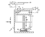
- FIG. 2 is a view of the inside of the housing 2 as viewed in the positive direction of the X axis.
- the jig apparatus 1 includes a support member 3, a horizontal rail 4, a vertical rail 30, a fixing mechanism 40, and a control unit 100 inside the housing 2.
- 2 shows the configuration of the support member 3 and the like provided corresponding to the holding member groups 110 and 120, and the same configuration is provided on the holding member groups 130 and 140 side.
- the support member 3 is two plate-like members whose longitudinal direction is the X-axis direction, and both ends in the longitudinal direction are fixed to the housing 2.
- a vertical rail 30 is attached to the support member 3 at a position corresponding to each holding member 10.
- the vertical rail 30 supports the holding member 10 so as to be movable in the vertical direction by supporting the movable rail 13 so as to be movable in the vertical direction.
- the control unit 100 controls the vertical position of the holding member and moves the above-described one or more second holding members in the vertical direction to a position where the workpiece is held.
- the position where the workpiece is held is a position where the horizontal contact portion 12 contacts the workpiece.
- the control unit 100 includes a fixing mechanism 40, a first moving mechanism 50, a second moving mechanism 60, and an instruction unit 70.
- FIG. 3 is a block diagram illustrating a hardware configuration of the control unit 100.
- the instruction unit 70 is electrically connected to each of the fixing mechanism 40, the first moving mechanism 50, and the second moving mechanism 60, and the fixing mechanism 40, the first moving mechanism 50, and the second moving mechanism. 60 operations are controlled.
- FIG. 4 is a block diagram illustrating an example of a hardware configuration of the instruction unit 70.
- the instruction unit 70 includes a control unit 71, a storage unit 72, an interface 73, and an operation unit 74.
- the control unit 71 includes a CPU (Central Processing Unit), a ROM (Read Only Memory), a RAM (Random Access Memory), and the like.
- the CPU stores a program stored in the ROM or the storage unit 72 using the RAM as a work area. By controlling the operation of each unit.
- the storage unit 72 includes a hard disk or the like, and stores data, programs, and the like used by the control unit 71 for control.
- the interface 73 is connected to the moving mechanism and the fixing mechanism described above via wiring and the like, and supplies a control signal that instructs the operation of each mechanism under the control of the control unit 71.
- the operation unit 74 includes an operation element used for instructing the movement mechanism and the fixing mechanism to perform an operation, and supplies operation data representing the content of the operation to the control unit 71 in accordance with a user operation.
- the instructing unit 70 has the above-described configuration and, for example, supplies the control signal described above according to a user operation on the operation unit 74 to instruct each mechanism to operate.
- FIG. 5 is a view of the moving rail 13, the vertical rail 30, and the fixing mechanism 40 as viewed from above.
- FIG. 5 shows the moving rail 13 of the holding member 10 included in the holding member group 110 that is located closest to the negative side of the X axis (the holding member 10 moving upward in FIG. 1). Yes.
- the moving rail 13 has a plate-like member at two positions (positions indicated by A1 and A2 in the figure) at the same distance to both ends in the width direction (direction orthogonal to the longitudinal direction). It is bent by an angle of less than 90 degrees (a shape formed by three sides excluding the bottom of the isosceles trapezoid).
- the movable rail 13 has an inner surface S131 on the side where both ends are bent, and an outer surface S132 on the opposite side.
- the vertical rail 30 includes an inner rail 31 and an outer rail 32.
- the inner rail 31 is a rail having the same shape as the moving rail 13 and smaller in size than the moving rail 13, and is disposed on the inner surface S 131 side of the moving rail 13.
- the outer rail 32 bends the plate-like member in the same direction in two positions (positions indicated by A3 and A4 in the figure) at the same distance to both ends in the width direction by an angle larger than 90 degrees. (The shape formed by the three sides excluding the upper base of the isosceles trapezoid).
- the outer rail 32 is arranged such that the bent portion is on the outer surface S132 side of the moving rail 13. As a result, the movable rail 13 is sandwiched between the inner rail 31 and the outer rail 32.
- gaps are generated between the moving rail 13, the inner rail 31, and the outer rail 32, respectively, so that the moving rail 13 can easily move in the vertical direction.
- the fixing mechanism 40 includes a first fixing part 41 and a second fixing part 42.
- the first fixing part 41 is a part of the fixing mechanism 40 that temporarily fixes the vertical position of the moving rail 13 and includes a magnet 411 and a hinge 412.
- the magnet 411 is attached to one metal fitting of the hinge 412, and the other metal fitting of the hinge 412 is attached to the outer rail 32.
- FIG. 5A the hinge 412 is bent and the magnet 411 is separated from the moving rail 13.
- FIG. 5B the hinge 412 is opened and the magnet 411 is attached to the moving rail 13. In this state, the moving rail 13 is fixed by the magnet 411 so as not to move in the vertical direction. In this way, the first fixing portion 41 temporarily fixes the vertical position of the moving rail 13.
- the second fixing portion 42 is a portion of the fixing mechanism 40 that fixes the vertical position of the moving rail 13 during processing, and includes a connecting portion 421, a pushing portion 422, and a driving portion 423.
- the connecting portion 421 is a rod-like member connected to the inner rail 31.
- the outer rail 32 is provided with a hole through which the connecting portion 421 passes.
- the connecting portion 421 is disposed through the hole, and the end opposite to the end connected to the inner rail 31 is connected to the pushing portion 422.
- the push-in portion 422 has a long and narrow plate-like member whose longitudinal direction is along the X-axis direction, and each connecting portion 421 connected to each inner rail 31 that supports each holding member 10 included in the holding member group 110. Each is connected.
- the driving unit 423 includes a driving device such as a motor and a gear, and drives the pushing unit 422 to move in the Y-axis direction.
- a driving device such as a motor and a gear
- the force with which the second fixing portion 42 fixes the position of the holding member 10 is larger than the same force with the first fixing portion 41, and the holding during processing is greater than when the second fixing portion 42 is temporarily fixed.
- the position of the member 10 in the vertical direction is made difficult to shift.
- Each holding member 10 included in another holding member group is also fixed in the vertical position by the same mechanism.
- the drive unit 423 moves the pushing unit 422 in a direction away from the moving rail 13
- the state in which the vertical position of each holding member 10 is fixed is released.
- fixed part 42 performs the fixation of the holding member 10, and cancellation
- the first moving mechanism 50 moves one or more holding members 10 in the vertical direction. More specifically, the first moving mechanism 50 includes a member 51 and a drive unit 52 that moves the member 51 in the vertical direction.
- the drive unit 52 includes, for example, a motor and moves the member 51 to a predetermined position in the vertical direction.
- the first moving mechanism 50 moves the holding member 10 in the vertical direction by moving the member 51 in the vertical direction using the drive unit 52.
- the position at which the holding member 10 is moved by the first moving mechanism 50 is a position determined by the user, for example, according to the dimensions of the workpiece, and is hereinafter referred to as “vertical position”.
- the vertical position is determined by a length range (for example, 0 mm to several hundred mm) determined according to the dimensions of the moving rail 13 and the drive unit 52.
- a vertical position represented by a length of 50 mm represents a position when the holding member 10 is pushed up by 50 mm from a position where the holding member 10 is not pushed up at all.
- the first moving mechanism 50 moves the holding member 10 among the plurality of holding members 10 according to the position of the member 51 in the X-axis direction. The mechanism of this movement will be described with reference to FIG.
- FIG. 6 is a view of the moving rail 13 and the member 51 as viewed from above.
- the moving rail 13 shown as 13a
- the moving rail 13 shown as 13b
- These moving rails 13 are arranged so that the inner side surfaces S131 (shown as S131a and S131b) of each other face each other.
- the member 51 has an attachment part 511 for attaching to the drive part 52 in the center, and is driven by the drive part 52 to move in the vertical direction.
- the member 51 is a plate-like member, and two protrusions 512 and 513 and a recess 514 between these protrusions are formed on the positive direction side of the Y axis. In addition, two protrusions 515 and 516 and a recess 517 between these protrusions are also formed on the negative direction side of the Y axis. These projecting portions are portions that protrude as compared with the recessed portions, and the recessed portions are portions that are recessed as compared with the projecting portions on the contrary. Due to these protrusions and depressions, the member 51 has a shape of “H” when viewed in the Y-axis direction. Further, the “H” shifts the protrusion 512 side in the positive direction of the X-axis. It is a member having an inclined shape.
- the protrusions 512 and 513 are in contact with the bent portions 132a and 133a of the moving rail 13a that are bent toward the inner surface S131a (132a is the positive side of the X axis). .
- the protrusions 515 and 516 do not contact the bent portions 132b and 133b (132b is the positive direction side of the X axis) of the moving rail 13b that is bent toward the inner surface S131b, and the bent portion 133b is depressed. It is located in the part 517.
- FIG. 6 (b) shows a moving rail 13c adjacent to the positive X-axis side of the moving rail 13a and a moving rail 13d adjacent to the X-axis positive direction side of the moving rail 13b.
- the member 51 moves in the positive direction of the X axis as shown in FIG. 6A, and the projection 512 is located between the bent portion 132a of the moving rail 13a and the bent portion 133c of the moving rail 13c.
- the bent portion 132a of 13a is positioned in the recessed portion 514.
- the protrusions 515 and 516 are in contact with the bent portions 132b and 133b of the moving rail 13b.
- This member 51 moves relative to the moving rails 13c and 13d to the same position as the moving rails 13a and 13b shown in FIG. 6A, so that the moving rail 13c moves and the moving rail 13d does not move. become. Further, when the member 51 moves relative to the moving rails 13c and 13d to the same position as the moving rails 13a and 13b shown in FIG. 6B, the moving rail 13d moves and the moving rail 13c does not move. It becomes a state.
- the member 51 is included in the second holding member group (similarly, the holding member group 120) when the holding member 10 included in the first holding member group (holding member group 110 in the example of FIG. 6) is moved.
- the first moving mechanism 50 uses this member 51 to move the holding member 10 in the vertical direction according to the position of the member 51 in the X-axis direction.
- the control unit 100 determines the holding members 10 belonging to another row (for example, holding member group 120). Restricts vertical movement. In the present embodiment, the control unit 100 restricts the vertical movement of the holding members 10 belonging to other rows to zero.
- a drive unit 52 in the jig device 1 that applies a vertical driving force to the holding member 10.
- the selected one can be moved in the vertical direction.
- the operation of the first moving mechanism 50 described above is also performed based on an instruction from the instruction unit 70.
- the second moving mechanism 60 moves the first moving mechanism 50 in the horizontal direction. More specifically, the second moving mechanism 60 includes, for example, a motor and wheels, and drives the first moving mechanism 50 to move it to a predetermined position in the X-axis direction. In the example of FIG. 2, the second moving mechanism 60 has the X-axis together with the first moving mechanism 50 while bringing the wheel into contact with the plate-like horizontal rail 4 provided in the housing 2 with the X-axis direction as the longitudinal direction. Move to a specified position in the direction. This position is a position where the member 51 contacts each of the moving rails 13 as shown in FIG. 6, and is determined corresponding to each holding member 10. Hereinafter, this position is referred to as “corresponding position”. For example, since the holding member groups 110 and 120 shown in FIG. 1 include 16 holding members 10, 16 corresponding positions are defined. Such an operation of the second moving mechanism 60 is also performed based on an instruction from the instruction unit 70.
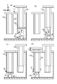
- FIG. 7 is a diagram for explaining a procedure for controlling the vertical position of the holding member 10. 7 shows the holding members 10a, 10b, 10c, and 10d, the first moving mechanism 50, and the second moving mechanism 60 as viewed from the positive direction side of the Y axis. In FIG. 7, the support member 3, the vertical rail 30, and the fixing mechanism 40 are omitted for easy understanding of the drawing. First, it is assumed that the user performs an operation of selecting the corresponding position of the holding member 10a and determining the vertical position represented by the length L1 with respect to the instruction unit 70 illustrated in FIG.
- the second movement mechanism 60 moves the first movement mechanism 50 to the corresponding position of the holding member 10a, and the first movement mechanism 50 holds it.
- the member 10a is moved upward to a vertical position where it is pushed upward by a length L1.
- the user operates the first fixing portion 41 in the state of FIG. 7A to temporarily fix the position of the holding member 10a, and selects the corresponding position of the holding member 10d with respect to the instruction portion 70.
- an operation for determining the vertical position represented by the length L2 is performed.
- the first moving mechanism 50 moves the members 51 below all the holding members 10 as shown in FIG. 60 moves the first moving mechanism 50 to the corresponding position of the holding member 10d as shown in FIG.
- the first moving mechanism 50 moves up the member 51 upward as shown in FIG. 7 (d) to the up / down position where the holding member 10d is pushed upward by the length L2. Move.
- the control unit 100 moves the first moving mechanism 50 to the corresponding position of the holding member 10 by the second moving mechanism 60, and moves the holding member 10 in the vertical direction by the first moving mechanism 50.
- the vertical position of the holding member 10 is controlled. Accordingly, the plurality of holding members 10 can be moved in the vertical direction only by providing one mechanism (first moving mechanism 50) for moving the holding member 10 in the vertical direction. Thereafter, the user repeats the operation of selecting the corresponding position and determining the vertical position of the next holding member 10 and temporarily fixing the holding member 10 by the first fixing portion 41 to hold the workpiece. Each holding member 10 is temporarily fixed at the vertical position determined by the user.
- the second fixing portion 42 fixes the vertical position of each holding member 10.
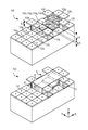
- FIG. 8 is a diagram illustrating an example of a state in which the vertical position of each holding member 10 is controlled.
- the six holding members 10 from the holding members 10e to 10j are fixed at the vertical position represented by the length L3.
- the holding members 10k, 10l are fixed at the vertical position represented by the length L4, and the holding members 10m, 10n are fixed at the vertical position represented by the length L5.
- the other holding members 10 other than those are fixed at the vertical position represented by the length 0 (that is, the position not pushed up at all).
- FIG. 8B shows a state where the workpiece 5 is placed on the jig apparatus 1 shown in FIG.
- the workpiece 5 includes horizontal portions (portions that face the horizontal direction when placed on the jig device) 6 and 7 and the like.
- the holding members 10k, 10l, 10m, 10n, 10o, 10p, 10p, and 10r form the step corresponding to the shape of the lower side of the workpiece 5,
- the placing portion 11 is in contact with a portion facing the lower side of the workpiece 5 (hereinafter referred to as a “lower portion”).
- the respective mounting portions 11 are shown hatched.
- These eight holding members 10 are the above-mentioned first holding members, that is, the holding members 10 selected as those on which the workpiece is placed.
- the lower portions of the workpiece are in contact with the placement portions 11 of the eight holding members 10.
- the six holding members 10 from the holding members around the first holding member to the holding members 10e to 10j are selected as the second holding members and moved to the predetermined vertical positions. It has been made.
- the horizontal contact portion 12 of each second holding member and the horizontal portion of the workpiece 5 are in contact with each other, so that the horizontal force from the workpiece 5 being processed is increased.
- the second holding member receives and holds the workpiece 5 so that the position of the workpiece 5 is not easily displaced in the horizontal direction.
- the control unit 100 controls the second holding member to move to a predetermined position in the vertical direction so that the first and second holding members cooperate to hold the workpiece 5. It is carried out.
- This position is a position where the second holding member holds the workpiece, and is determined according to the shape, size, and arrangement of the workpiece.
- control unit 100 the horizontal contact portion of the second holding member comes into contact with the horizontal portion of the workpiece 5 placed on the placement portion of the first holding member, and the workpiece 5 is processed. Control is performed so that In the holding members 10k, 10l, 10m, and 10n, the lower portion of the workpiece is in contact with each placement portion 11, and the horizontal portion of the workpiece is in contact with each horizontal contact portion 12. As described above, the control unit 100 may perform control so that the holding member 10 also serving as the first and second holding members exists depending on the shape and size of the workpiece.
- control unit 100 regards the holding members 10m and 10n as the first holding members
- the control unit 100 regards the holding members 10k and 10l as the second holding members and moves them up and down to move the holding members 10k and 10l.
- the holding members 10f, 10g, 10h and 10i are regarded as the second holding member and moved in the vertical direction.
- the processing portion 8 (the portion shown by hatching in FIG. 8B) included in the horizontal portion 6 of the processing target object 5 is processed.
- the processing portion refers to a portion to be processed in the processing target.
- the holding members around the first holding member include those that are not adjacent to the first holding member (other holding members are sandwiched therebetween), such as the holding members 10u and 10v. Also good. Since these holding members are not selected as the second holding members, none of the holding members is moved upward by the control unit 100.
- the processing unit 8 is exposed without being blocked by the holding member 10.
- the holding member 10 does not get in the way. . If all the holding members 10 around the first holding member come into contact with the horizontal portion of the workpiece 5, the holding member 10 blocks the processed portion when the horizontal portion includes the processed portion. May interfere with processing.
- the control unit 100 moves only the selected holding member around the first holding member as the second holding member in the vertical direction, the horizontal part of the workpiece is processed.
- the holding member 10 can be prevented from interfering with processing.
- FIG. 9 is a diagram illustrating an example of a state in which the upper holding member 20 is attached.
- the upper holding members 20 are respectively attached to the attachment portions 14 of the six holding members 10e to 10j shown in FIG. Each is in contact. Thereby, the position of the processing target object 5 can be made difficult to shift upward during processing.
- the processing part when the processing part is contained in the upper part 9, it is good to attach the upper holding member 20 so that the processing part may not be contacted. Further, depending on the shape and size of the workpiece, a gap may be generated between the workpiece and the horizontal contact portion 12. In such a case, the workpiece may be pressed from above by attaching the upper holding member 20 to the second holding member. As a result, the second holding member receives the horizontal force from the workpiece to be processed by the frictional force generated between the upper holding member 20 and the workpiece, and suppresses the displacement of the horizontal position. Hold the workpiece.
- the position at which the second holding member holds the workpiece is not the position at which the horizontal contact portion 12 of the second holding member contacts the workpiece, but the second holding member is the upper holding member. It becomes a position which receives the force of the horizontal direction from a workpiece through 20. That is, the second holding member does not necessarily have to be in contact with the processing object at the position where the processing object is held.
- FIG. 10 is a view of the holding member 10 as viewed in the X-axis direction.
- FIG. 10A shows a state in which the lower surface 16 of the rectangular member 15 is in contact with the workpiece 5a and presses the workpiece 5a.
- the holding member 10 including the rectangular member 15 receives the horizontal force from the workpiece 5a being processed by the frictional force generated on the lower surface 16 and the workpiece 5a, and holds the workpiece 5a.
- the holding member 10 functions as the second holding member.
- FIG. 10B a workpiece 5b having an inclined surface 9 at the upper corner is shown.
- the workpiece 5b may be held by bringing the corners of the horizontal contact portion 12 and the lower surface 16 into contact with the surface 9 of the workpiece 5b.
- the object to be processed enters and is held below the first member (square member 15) of the second holding member.
- Such a holding method is possible because the position of the second holding member in contact with the workpiece is in the horizontal direction with respect to the moving rail 13 as the second member is closer to the workpiece. It has become. Note that this positional relationship between the contact portion of the second holding member and the moving rail 13 is the same when the holding member 10 is viewed in the Y-axis direction.
- the workpiece 5 shown in FIG. 9 has a dimension in the X-axis direction that is an integral multiple (four times) of the dimension in the X-axis direction of the mounting portion 11, and the dimension in the Y-axis direction is also the Y-axis of the mounting portion 11. Since it is an integral multiple (2 times) of the dimension in the direction, it can be held in contact with the horizontal contact portion 12 of the second holding member without entering the space below the rectangular member 15.
- the workpieces 5a and 9b shown in FIG. 10 have a dimension in the Y-axis direction that is not an integral multiple of the dimension in the Y-axis direction of the mounting portion 11, but the space below the rectangular member 15 It can be held in.
- the positional relationship between the contact portion in the second holding member and the moving rail 13 is as described above, and in other cases (that is, the horizontal position of the contact portion in the second holding member).
- the degree of freedom of the dimension of the processing object that can be held can be improved.
- by selecting the first holding member and the second holding member according to the shape and size of the processing object various shapes of the processing object can be obtained. It can be held for easy processing.
- the first fixing portion is not limited to that described in the embodiment. Instead of fixing the moving rail 13 using a magnet, the first fixing portion is provided with, for example, a plurality of holes arranged in the vertical direction in the moving rail 13, and a rod-shaped member is inserted into the hole to It may be fixed, or may be fixed by sandwiching the moving rail 13 like a vise. In short, the 1st fixing
- a driving unit that has a motor or the like and is driven to rotate the hinge 412 is provided, and the instruction unit 70 instructs the operation of the driving unit,
- the position of the moving rail 13 in the vertical direction is temporarily fixed. Thereby, the user can move each holding member 10 to the determined vertical position only by operating the instruction unit 70.
- Second fixing portion is not limited to that described in the embodiment.
- the pusher 422 may be manually operated by the user, or a driving unit may be provided for each holding member 10 included in the holding member group so that the holding member 10 is fixed to each holding member 10. Good.
- the second fixing portion only needs to fix the vertical position of the moving rail 13 during processing.
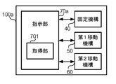
- FIG. 11 is a diagram illustrating an example of a hardware configuration of a control unit according to the present modification.
- an instruction unit 70a including the acquisition unit 701 and a control unit 100a including the instruction unit 70a are illustrated.
- the acquisition unit 701 acquires the vertical position described above, that is, information indicating the vertical position of each of the one or more second holding members described above (hereinafter referred to as “position information”).
- position information is information corresponding to the shape of the workpiece.
- the position information includes, for example, an ID (for example, an identifier represented by a numerical value or a symbol such as 10a or 10b) assigned to each holding member 10 and a numerical value (for example, a length that is pushed up) associated with the ID. Is represented).
- the position information “10e, L3” indicates that the vertical position of the holding member 10e illustrated in FIG. 8 is the length L3.
- the acquisition unit 701 stores position information indicating the vertical position of each second holding member (which may include the first holding member) determined by, for example, the user operating the operation unit 74 illustrated in FIG. The position information is acquired by storing the information in the unit 72 and reading it from the storage unit 72. If the interface 73 is also connected to an external device, the acquisition unit 701 may acquire position information transmitted from the external device.
- the instruction unit 70a instructs the operations of the first moving mechanism 50 and the second moving mechanism 60 so as to move the holding member 10 indicated by the position information acquired by the acquiring unit 701 to the vertical position indicated by the position information. .
- the control unit 100a moves the above-described one or more second holding members based on the position information acquired by the acquisition unit 701. Specifically, the control unit 100a moves the second holding member to the vertical position indicated by the acquired position information.
- the vertical position used in the past can be reused by storing the positional information indicating the vertical position determined for a certain workpiece. Also, by exchanging the position information between the apparatuses, the vertical position determined by a certain jig apparatus can be reproduced by another jig apparatus.
- the first moving mechanism may move the holding member 10 by a method different from that of the embodiment.
- the first moving mechanism moves the holding member 10 in the vertical direction using a moving member having a shape different from that of the member 51.
- the first moving mechanism includes, for example, a moving member having only one of the protrusion and the depression and a rotation driving unit that rotates the moving member, and the rotation driving unit rotates the moving member, thereby The holding member 10 included in the first holding member group is moved, or the holding member 10 included in the second holding member group is moved.
- the first moving mechanism may move the holding member 10 by simply using a rod-shaped member as the moving member instead of the member having the shape of “H” like the member 51, or may be 2 instead of one. You may move the above holding member 10 simultaneously.
- the first moving mechanism is not limited to the motor exemplified in the embodiment, and the holding member 10 may be moved using, for example, hydraulic pressure or atmospheric pressure. In short, the first moving mechanism only needs to move one or more holding members 10 in the vertical direction.
- the second movement mechanism may move the first movement mechanism by a method different from the embodiment.
- the second moving mechanism includes an endless belt provided along the holding member group and to which the first moving mechanism is fixed, and a rotation driving unit that rotates the belt, and the rotation driving unit rotates the belt.
- the first moving mechanism is moved.
- the 2nd moving mechanism moved the 1st moving mechanism along the holding member group in embodiment, it is not restricted to this.
- the second moving mechanism may move the first moving mechanism so as to move back and forth between different holding member groups. .
- the holding member 10 is arranged as in the jig apparatus shown in FIG.
- the first moving mechanism is first moved from the holding member group 110 side in the negative direction of the Y axis to hold the holding member group.
- the second moving mechanism may be any mechanism that can move the first moving mechanism to the corresponding position.
- the holding member is not limited to that described in the embodiment.
- the mounting portion and the horizontal contact portion may be curved surfaces instead of flat surfaces, undulations may be provided, or rubber or the like may be attached.
- the placement portion is not limited to a square, and may be a rectangle, a triangle, a circle, or the like
- the horizontal contact portion is not limited to a rectangle, but may be a square, a triangle, a circle, or the like.
- the holding members need only be arranged so as to be arranged two-dimensionally so that the position of the processing object does not shift when contacting the processing object.
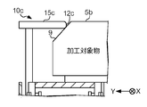
- FIG. 12 is a view of the holding member 10c of this modification as viewed in the X-axis direction.
- the holding member 10c is selected as the second holding member, and the horizontal contact portion 12c of the rectangular member 15c is in contact with the oblique surface 9 of the workpiece 5b shown in FIG.
- the contact portion horizontal contact portion 12c
- the contact portion that comes into contact with the workpiece is rounded.
- the contact portion has a sharp shape, the object to be processed may be damaged.
- the holding member 10c shown in FIG. 12 it is possible to make the object to be processed less likely to be damaged compared to that case. Moreover, it can make it hard to damage a process target object also by making a contact part have elasticity.
- FIG. 13 is a view of the holding member 10d of the present modification viewed in the X-axis direction.
- the rectangular member 15d of the holding member 10d is supported so as to be movable in the horizontal direction from the state of being held in contact with the workpiece 5 shown in FIG.
- the horizontal position of the contact portion can be changed.
- the horizontal contact portion 12d even if the workpiece 5d has a dimension in the Y-axis direction larger than that of the workpiece 5. Can be held in contact with each other.
- FIG. 14 is a view of the holding member 10e of this modification as viewed in the X-axis direction.
- the rectangular member 15e of the holding member 10e can be folded at a predetermined position in the Y-axis direction.
- the rectangular member 15e has two horizontal contact parts, a horizontal contact part 12e-1 before folding and a horizontal contact part 12e-2 after folding.
- the horizontal position of the contact portion can be changed.
- the horizontal contact portion even if the workpiece 5d has a dimension in the Y-axis direction larger than that of the workpiece 5. 12e-2 can be held in contact.
- the holding member may have a protruding member that protrudes in the horizontal direction from the horizontal contact portion and can fix the position in the horizontal direction in the protruding state.
- the horizontal contact portion is fixed by protruding the projecting member and fixing the horizontal position when contacting the workpiece.
- the gap between the workpiece and the workpiece can be filled so that the horizontal position of the workpiece can hardly be displaced.
- the holding member has moved in the vertical direction in the direction perpendicular to the mounting portion 11 arranged in parallel with the horizontal plane, but the present invention is not limited thereto, and the holding member has the vertical direction in the direction that forms an angle with the horizontal plane. You may move. Even in this case, by selecting the second holding member so as not to obstruct the processing portion, it is possible to prevent the holding member 10 from interfering with the processing as in the embodiment.
- FIG. 15 is a diagram illustrating an appearance of the jig device 1f according to the present modification.
- the holding member 10f included in the jig device 1 is configured such that the horizontal contact portion 12f is hidden by the housing 2 even when it is moved to the uppermost position.
- the horizontal contact portion 12f also receives the horizontal force received from the workpiece, so that a larger horizontal force can be applied compared to the case where only the rail member receives the force as in the embodiment, for example. I can take it.
- the plurality of first members are arranged in a grid shape, but the present invention is not limited to this.
- the first members may have a hexagonal shape when viewed from above, and the first members may be arranged so as to spread.
- FIG. 16 is a view of the plurality of first members 15g of this modification as viewed from above.
- the plurality of first members 15g are arranged in rows in three directions B1, B2, and B3 that form an angle of 60 degrees.
- a plurality of holding members are arranged in two dimensions. Even when the plurality of first members 15g are arranged in this way, similarly to the embodiment, it is possible to hold the objects to be processed having various shapes so as to be easily processed.
- Upper holding member The upper holding member is not limited to that described in the embodiment. Depending on the shape, size, and material of the workpiece to be held, upper holding members of various shapes and sizes may be attached to the holding member. In the embodiment, one upper holding member is attached to the case holding member, but two or more upper holding members may be attached. Further, an upper holding member having a different shape or size may be attached to each holding member. In short, the member that holds the workpiece from above may be attached to the holding member as the upper holding member.
Landscapes
- Engineering & Computer Science (AREA)
- Mechanical Engineering (AREA)
- Jigs For Machine Tools (AREA)
- Manipulator (AREA)
- Supply And Installment Of Electrical Components (AREA)
Abstract
Priority Applications (5)
| Application Number | Priority Date | Filing Date | Title |
|---|---|---|---|
| ES15737645T ES2747223T3 (es) | 2014-01-20 | 2015-01-20 | Aparato de plantilla |
| JP2015557921A JP5978409B2 (ja) | 2014-01-20 | 2015-01-20 | 治具装置 |
| US15/113,016 US10071451B2 (en) | 2014-01-20 | 2015-01-20 | Jig apparatus |
| CN201580004320.7A CN105899327B (zh) | 2014-01-20 | 2015-01-20 | 夹具装置 |
| EP15737645.0A EP3098023B1 (fr) | 2014-01-20 | 2015-01-20 | Appareil de montage |
Applications Claiming Priority (2)
| Application Number | Priority Date | Filing Date | Title |
|---|---|---|---|
| JP2014-007842 | 2014-01-20 | ||
| JP2014007842 | 2014-01-20 |
Publications (1)
| Publication Number | Publication Date |
|---|---|
| WO2015108199A1 true WO2015108199A1 (fr) | 2015-07-23 |
Family
ID=53543080
Family Applications (1)
| Application Number | Title | Priority Date | Filing Date |
|---|---|---|---|
| PCT/JP2015/051376 Ceased WO2015108199A1 (fr) | 2014-01-20 | 2015-01-20 | Appareil de montage |
Country Status (8)
| Country | Link |
|---|---|
| US (1) | US10071451B2 (fr) |
| EP (1) | EP3098023B1 (fr) |
| JP (1) | JP5978409B2 (fr) |
| CN (1) | CN105899327B (fr) |
| ES (1) | ES2747223T3 (fr) |
| MY (1) | MY178974A (fr) |
| TR (1) | TR201909991T4 (fr) |
| WO (1) | WO2015108199A1 (fr) |
Cited By (1)
| Publication number | Priority date | Publication date | Assignee | Title |
|---|---|---|---|---|
| JP2023064226A (ja) * | 2021-10-26 | 2023-05-11 | 株式会社ツガミ | 制御ユニット及び工作機械 |
Citations (8)
| Publication number | Priority date | Publication date | Assignee | Title |
|---|---|---|---|---|
| US1674291A (en) * | 1922-12-22 | 1928-06-19 | Ingersoll Milling Machine Co | Work fixture |
| US2399824A (en) * | 1943-08-09 | 1946-05-07 | Irving L Pressman | Adjustable jig and holder |
| US2472083A (en) * | 1945-07-03 | 1949-06-07 | Carl O Bartholdy | Machine tool fixture |
| JPH0192328U (fr) * | 1987-12-10 | 1989-06-16 | ||
| JPH04118905A (ja) * | 1990-01-22 | 1992-04-20 | Tabuchi Denki Kk | 誘導電磁器 |
| JPH10202456A (ja) * | 1997-01-23 | 1998-08-04 | Nissan Motor Co Ltd | クランプ装置 |
| JP2000343361A (ja) * | 1999-06-04 | 2000-12-12 | Akira Ishikawa | 支持装置 |
| JP2006297595A (ja) | 2006-06-26 | 2006-11-02 | Nagase Integrex Co Ltd | ワーク載置台 |
Family Cites Families (18)
| Publication number | Priority date | Publication date | Assignee | Title |
|---|---|---|---|---|
| US4200272A (en) * | 1978-06-12 | 1980-04-29 | Bcira | Holder for irregularly shaped articles |
| JPH0719696Y2 (ja) * | 1988-10-17 | 1995-05-10 | トヨタ自動車株式会社 | 位置決め治具 |
| JPH02303771A (ja) * | 1989-05-19 | 1990-12-17 | Sanmei Denki Kk | 自在治具 |
| JPH0417062U (fr) * | 1990-05-28 | 1992-02-12 | ||
| JPH0476341U (fr) * | 1990-11-15 | 1992-07-03 | ||
| DK0623065T3 (da) * | 1992-01-25 | 1997-10-20 | Goetz Metall Anlagen | Formspændebakker og fremgangsmåde til fastspænding af arbejdsstykker |
| US6250619B1 (en) * | 1998-02-03 | 2001-06-26 | Cna Manufacturing Systems, Inc. | Clamp suitable for use at high temperatures in a flexible tooling apparatus |
| GB0329979D0 (en) | 2003-12-24 | 2004-01-28 | Surface Generation Ltd | Workpiece support |
| ITFI20060171A1 (it) * | 2006-07-05 | 2008-01-06 | Paolino Bacci Srl | Macchina utensile o centro di lavoro con doppia registrazione a controllo numerico degli organi di bloccaggio |
| CA2707163A1 (fr) * | 2007-11-30 | 2009-06-04 | Flow International Corporation | Systeme a embase flexible pour usinage de pieces de fabrication |
| CN100551609C (zh) * | 2008-04-11 | 2009-10-21 | 清华大学 | 机器人化智能工装系统 |
| US8181948B2 (en) | 2008-06-12 | 2012-05-22 | John Blick | Tilt machining device and method |
| DE202009006436U1 (de) * | 2009-05-05 | 2009-07-23 | Horst Witte Gerätebau Barskamp KG | System zum Aufspannen von Werkstücken |
| JP5763070B2 (ja) * | 2009-08-06 | 2015-08-12 | パー システムズ, インコーポレイテッド | フレキシブル固定具 |
| CN201833202U (zh) * | 2010-07-30 | 2011-05-18 | 中国航空工业集团公司北京航空制造工程研究所 | 一种柔性夹持工装系统 |
| CN102825484A (zh) * | 2011-06-13 | 2012-12-19 | 江南大学 | 基于相变材料的柔性夹具 |
| JP5926961B2 (ja) * | 2012-01-10 | 2016-05-25 | 本田技研工業株式会社 | ワーク支持装置 |
| CN103170859B (zh) * | 2013-03-27 | 2015-04-22 | 东北大学 | 一种薄壁大部件柔性夹具 |
-
2015
- 2015-01-20 US US15/113,016 patent/US10071451B2/en active Active
- 2015-01-20 CN CN201580004320.7A patent/CN105899327B/zh active Active
- 2015-01-20 MY MYPI2016001364A patent/MY178974A/en unknown
- 2015-01-20 EP EP15737645.0A patent/EP3098023B1/fr active Active
- 2015-01-20 TR TR2019/09991T patent/TR201909991T4/tr unknown
- 2015-01-20 ES ES15737645T patent/ES2747223T3/es active Active
- 2015-01-20 WO PCT/JP2015/051376 patent/WO2015108199A1/fr not_active Ceased
- 2015-01-20 JP JP2015557921A patent/JP5978409B2/ja active Active
Patent Citations (8)
| Publication number | Priority date | Publication date | Assignee | Title |
|---|---|---|---|---|
| US1674291A (en) * | 1922-12-22 | 1928-06-19 | Ingersoll Milling Machine Co | Work fixture |
| US2399824A (en) * | 1943-08-09 | 1946-05-07 | Irving L Pressman | Adjustable jig and holder |
| US2472083A (en) * | 1945-07-03 | 1949-06-07 | Carl O Bartholdy | Machine tool fixture |
| JPH0192328U (fr) * | 1987-12-10 | 1989-06-16 | ||
| JPH04118905A (ja) * | 1990-01-22 | 1992-04-20 | Tabuchi Denki Kk | 誘導電磁器 |
| JPH10202456A (ja) * | 1997-01-23 | 1998-08-04 | Nissan Motor Co Ltd | クランプ装置 |
| JP2000343361A (ja) * | 1999-06-04 | 2000-12-12 | Akira Ishikawa | 支持装置 |
| JP2006297595A (ja) | 2006-06-26 | 2006-11-02 | Nagase Integrex Co Ltd | ワーク載置台 |
Cited By (2)
| Publication number | Priority date | Publication date | Assignee | Title |
|---|---|---|---|---|
| JP2023064226A (ja) * | 2021-10-26 | 2023-05-11 | 株式会社ツガミ | 制御ユニット及び工作機械 |
| JP7724132B2 (ja) | 2021-10-26 | 2025-08-15 | 株式会社ツガミ | 制御ユニット及び工作機械 |
Also Published As
| Publication number | Publication date |
|---|---|
| US20170001274A1 (en) | 2017-01-05 |
| TR201909991T4 (tr) | 2019-07-22 |
| CN105899327B (zh) | 2018-04-03 |
| CN105899327A (zh) | 2016-08-24 |
| MY178974A (en) | 2020-10-26 |
| EP3098023A4 (fr) | 2017-11-15 |
| EP3098023A1 (fr) | 2016-11-30 |
| EP3098023B1 (fr) | 2019-06-26 |
| ES2747223T3 (es) | 2020-03-10 |
| JPWO2015108199A1 (ja) | 2017-03-23 |
| US10071451B2 (en) | 2018-09-11 |
| JP5978409B2 (ja) | 2016-08-24 |
Similar Documents
| Publication | Publication Date | Title |
|---|---|---|
| JP2014086472A (ja) | クランプ装置及びワーク搬送ロボット | |
| US12157193B2 (en) | Multi-product pallet device, control system for multi-product pallet device, displacement-restricting mechanism, and conforming mechanism | |
| US20250289046A1 (en) | Bending system and correcting method for tool misalignment | |
| JP5978409B2 (ja) | 治具装置 | |
| JP5012747B2 (ja) | 部品位置決め方法および部品位置決め用治具 | |
| JP6452874B1 (ja) | 金属加工装置、ロボット、及び金属加工方法 | |
| CN1903502B (zh) | 夹具、被加工物的制造方法及缝纫机机头的制造方法 | |
| JP4274120B2 (ja) | ワーク位置決め搬送装置,ワーク位置決め搬送方法およびワーク位置決め搬送台車 | |
| JP2010201481A (ja) | 位置決め装置および位置決め方法 | |
| JP5251649B2 (ja) | スポット溶接用チップ取り外し装置 | |
| JP2020172016A (ja) | 多品種対応パレット装置、多品種対応パレット装置の制御システム、変位規制機構、及び、ならい機構 | |
| CN102238861B (zh) | 夹持装置 | |
| KR102253409B1 (ko) | 워크 유지 기구 | |
| JP2012091255A (ja) | 位置決め治具 | |
| CN210819590U (zh) | 夹具及移料机器人 | |
| JP4618199B2 (ja) | フレキシブル基板固着用治具 | |
| JP2010247259A (ja) | 基準ピンの位置決め構造及び位置決め方法 | |
| JP2007172845A (ja) | 管状光源用ソケット | |
| JP2015098078A (ja) | ワイヤ放電加工機における棒状または板状のワークの保持具 | |
| JPH0366540A (ja) | ロケートピンによるワーク位置決め方法 | |
| JP2014069285A (ja) | ワーク位置決め装置 | |
| JP2015152380A (ja) | 基板検査装置および基板検査方法 | |
| CN120421891B (zh) | 移载工装 | |
| TWI505051B (zh) | A plurality of electronic components can be positioned at the same time positioning device and its application of the operating equipment | |
| US20240375167A1 (en) | Bending system, and divided tool arrangement method |
Legal Events
| Date | Code | Title | Description |
|---|---|---|---|
| ENP | Entry into the national phase |
Ref document number: 2015557921 Country of ref document: JP Kind code of ref document: A |
|
| 121 | Ep: the epo has been informed by wipo that ep was designated in this application |
Ref document number: 15737645 Country of ref document: EP Kind code of ref document: A1 |
|
| NENP | Non-entry into the national phase |
Ref country code: DE |
|
| WWE | Wipo information: entry into national phase |
Ref document number: 15113016 Country of ref document: US |
|
| REEP | Request for entry into the european phase |
Ref document number: 2015737645 Country of ref document: EP |
|
| WWE | Wipo information: entry into national phase |
Ref document number: 2015737645 Country of ref document: EP |
|
| WWE | Wipo information: entry into national phase |
Ref document number: IDP00201605165 Country of ref document: ID |