WO2015111320A1 - 巻鉄心及び巻鉄心の製造方法 - Google Patents
巻鉄心及び巻鉄心の製造方法 Download PDFInfo
- Publication number
- WO2015111320A1 WO2015111320A1 PCT/JP2014/082841 JP2014082841W WO2015111320A1 WO 2015111320 A1 WO2015111320 A1 WO 2015111320A1 JP 2014082841 W JP2014082841 W JP 2014082841W WO 2015111320 A1 WO2015111320 A1 WO 2015111320A1
- Authority
- WO
- WIPO (PCT)
- Prior art keywords
- iron core
- core material
- wound
- corner portion
- corner
- Prior art date
- Legal status (The legal status is an assumption and is not a legal conclusion. Google has not performed a legal analysis and makes no representation as to the accuracy of the status listed.)
- Ceased
Links
Images


Classifications
-
- H—ELECTRICITY
- H01—ELECTRIC ELEMENTS
- H01F—MAGNETS; INDUCTANCES; TRANSFORMERS; SELECTION OF MATERIALS FOR THEIR MAGNETIC PROPERTIES
- H01F27/00—Details of transformers or inductances, in general
- H01F27/24—Magnetic cores
- H01F27/245—Magnetic cores made from sheets, e.g. grain-oriented
- H01F27/2455—Magnetic cores made from sheets, e.g. grain-oriented using bent laminations
-
- H—ELECTRICITY
- H01—ELECTRIC ELEMENTS
- H01F—MAGNETS; INDUCTANCES; TRANSFORMERS; SELECTION OF MATERIALS FOR THEIR MAGNETIC PROPERTIES
- H01F3/00—Cores, Yokes, or armatures
- H01F3/04—Cores, Yokes, or armatures made from strips or ribbons
-
- H—ELECTRICITY
- H01—ELECTRIC ELEMENTS
- H01F—MAGNETS; INDUCTANCES; TRANSFORMERS; SELECTION OF MATERIALS FOR THEIR MAGNETIC PROPERTIES
- H01F41/00—Apparatus or processes specially adapted for manufacturing or assembling magnets, inductances or transformers; Apparatus or processes specially adapted for manufacturing materials characterised by their magnetic properties
- H01F41/02—Apparatus or processes specially adapted for manufacturing or assembling magnets, inductances or transformers; Apparatus or processes specially adapted for manufacturing materials characterised by their magnetic properties for manufacturing cores, coils, or magnets
- H01F41/0206—Manufacturing of magnetic cores by mechanical means
- H01F41/0233—Manufacturing of magnetic circuits made from sheets
- H01F41/024—Manufacturing of magnetic circuits made from deformed sheets
Definitions
- Embodiments of the present invention relate to a wound iron core in which a plurality of iron core materials are wound and a method for manufacturing the wound iron core.
- iron loss which is a power loss generated in iron cores
- a laminated iron core in which cut thin silicon steel plates are laminated and a wound iron core in which cut thin silicon steel plates are wound are known.
- the wound iron core is more advantageous than the laminated iron core from the viewpoint of reducing iron loss because the flow of magnetic flux in the iron core is not easily inhibited.
- Patent Document 1 discloses an example of a method for manufacturing such a wound iron core.
- This type of wound iron core is generally manufactured by the following method. That is, an iron core material is wound from a thin silicon steel plate into a circular winding die while being cut every turn, that is, every turn. Thereafter, the wound iron core material is pressed against the inside and outside of the iron core material and pressed, thereby forming a substantially rectangular iron core window at the center. At this time, bending stress that causes an increase in iron loss is generated in the iron core material constituting the wound iron core. Therefore, a treatment for relaxing the residual stress and restoring the iron loss characteristics, that is, an annealing treatment for cooling the wound core after heating it to about 800 ° C., for example, is performed.
- the wound core When the winding is assembled to the wound core, the wound core is once opened at the cut portion of each core material, the winding is assembled to the side of the wound core, and then the wound core is closed again. At this time, if a gap is generated at the joint where the cut portions of each iron core material are joined, for example, the shape of the wound core is distorted, causing an increase in iron loss. For this reason, the generation of a gap is suppressed as much as possible by tightening the periphery of the wound iron core with a tightening band.
- the gap generated at the joint where the cut portions of each core material are joined must be made as small as possible. Therefore, at present, precise dimensional control is required in each of a series of processes for manufacturing a wound iron core, that is, a silicon steel sheet cutting process, a winding process, a forming process, an annealing process, and a winding assembly process. Moreover, especially in the assembly
- the present embodiment does not require precise dimensional control in the manufacturing process, can be manufactured without causing an increase in manufacturing man-hours, and can suppress an increase in iron loss, And the manufacturing method which manufactures the said wound iron core is provided.
- the wound iron core according to the present embodiment is a wound iron core having a rectangular window portion at the center, in which a plurality of iron core materials each having at least one cut portion are wound for each turn, and having 4 in the window portion.
- a corner portion provided at a corner; and a side portion connecting the corner portions.
- the space factor of the said iron core material in a corner part is lower than the space factor of the said iron core material in the edge part except the said corner part.
- the manufacturing method of the wound iron core which concerns on this embodiment winds loosely the several core material which has a cutting part of at least one place for every volume, and is centering in the state which joined the said cutting part of each iron core material.
- a wound core in which the space factor of the iron core material in the corner portion is lower than the space factor of the iron core material in the side portion excluding the corner portion is manufactured.
- the manufacturing method of the wound iron core which concerns on this embodiment loosely laminates the iron core material which has at least one cutting part for every volume, and the part which forms a corner part is bent beforehand, and each iron core By forming a rectangular window at the center in a state where the cut portions of the material are joined, the space factor of the iron core material in the corner portion is more than the space factor of the iron core material in the side portion excluding the corner portion.
- a method of manufacturing a lower wound core wherein the length of the portion forming the side portion of the one iron core material is set to the inner core of the iron core material before the iron core material is laminated. The length of the part that forms the corner portion in one of the iron core materials is bent in the iron core material inside the iron core material. Part forming the corner part Bent so that a predetermined amount greater than the length of the.
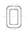
- a wound iron core 10 shown in FIG. 1 has a configuration in which a plurality of iron core members 10a obtained by cutting a silicon steel plate (not shown) is wound.
- the wound iron core 10 has a substantially rectangular window 11 at the center.
- the wound core 10 has four corner portions 12 provided at four corners of the window portion 11 and four side portions 13 excluding these corner portions 12.
- the side portion 13 connects the corner portions 12.
- the side portion 13 includes a long side portion 13a to which a winding (not shown) is assembled, and a short side portion 13b shorter than the long side portion 13a.
- the plurality of iron core members 10a constituting the wound core 10 are cut from the silicon steel plate for one turn, that is, for one turn. Therefore, in this case, one turn portion is provided for each turn. ing.
- the junction part 14 is formed in the part to which a cutting part is joined in each iron core material 10a, ie, the both ends of each iron core material 10a.
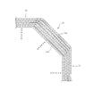
- the space factor of the iron core material 10 a in the corner portion 12 is lower than the space factor of the iron core material 10 a in the side portion 13. That is, the iron core material 10a is densely laminated at the side portion 13, but the iron core material 10a is not densely laminated at the corner portion 12, and there is a gap between the iron core materials 10a. In this case, each iron core material 10a has a gap for each sheet.
- the space factor indicates the ratio of the area occupied by the iron core material 10a to the cross-sectional area of the wound iron core 10. The higher the space factor, the denser the core material 10a is laminated. Show.
- the wound core 10 has a configuration in which core groups 15a, 15b,... Are formed for each predetermined number of cores 10a. That is, one iron core group 15a, 15b,... Is formed each time a predetermined number of iron cores 10a are stacked from the inner side that is closest to the window 11 side.
- the number of the iron core materials 10a which form one iron core material group can be changed and implemented suitably.
- the iron core material 10a included in each of the iron core material groups 15a, 15b,... Is wound so that the joint portions 14 to which the cut portions are joined are displaced in the circumferential direction and positioned stepwise.
- the position Pb of the joint portion 14 of the iron core material 10a wound on the innermost side in the iron core material group 15b is the iron core wound on the innermost side in the iron core material group 15a adjacent to the inner side of the iron core material group 15b. It almost or completely coincides with the position Pa of the joint portion 14 of the material 10a.
- the circumferential length Lb of the iron core material 10 a wound on the innermost side in the iron core material group 15 b is wound on the outermost side in the iron core material group 15 a adjacent to the inner side of the iron core material group 15 b. It is larger than the circumferential length La of the iron core material 10a to be rotated. In this case, the circumferential length Lb is set to be longer by a length corresponding to the plate thickness d of the iron core material 10a.
- This manufacturing method includes a cutting process of a silicon steel sheet, a winding process of a core material, a forming process of a wound core, and an annealing process of the wound core.
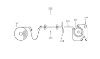
- the manufacturing apparatus 100 is configured to sequentially feed the silicon steel strip M by the feeder 101. And the manufacturing apparatus 100 cuts the iron core material 10a for one volume, ie, one turn, sequentially from the silicon steel strip M sent sequentially by the cutting blade 102.
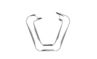
- Step 1 for example, as shown in FIG. 5, the manufacturing apparatus 100 sequentially winds the iron core material 10 a obtained from the silicon steel strip M around a circular winding die 103. At this time, each iron core material 10a is wound more loosely than before. It should be noted that the degree of loosening the iron core material 10a can be appropriately adjusted according to the space factor of the corner portion 12 of the target wound iron core 10. That is, the space factor of the corner portion 12 can be further lowered as the degree of loosening the iron core material 10a is increased.
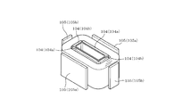
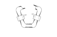
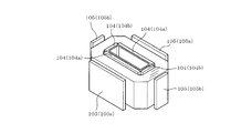
- the molds 104 and 105 are applied to the four inner portions and the four outer portions of the plurality of iron cores 10 a wound and stacked. And the four places of the iron core material 10a are suitably pressed along the lamination direction by the molds 104 and 105.
- a press is performed in the state which joined the cutting part of each iron core material 10a.
- the side portions 13 are formed in the portions to be pressed, that is, the portions sandwiched by the molds 104 and 105, respectively, and the other portions, that is, the portions that are not pressed, respectively.
- a corner portion 12 is formed.
- the “part that is not pressed” is, in other words, a part that is not sandwiched between the molds 104 and 105.
- each iron core material 10a is wound more loosely than before, the iron core material 10a in the portion where the corner portion 12 is formed is appropriately deformed during pressing.
- the corner portion 12 is appropriately deformed, the deformation of the iron core material 10a accompanying the press is absorbed. Therefore, it can prevent that the cutting part of each iron core material 10a, ie, the junction part 14, opens after a press.
- the molds 104 and 105 include two sets of long side molds 104a and 105a and two sets of short side molds 104b and 105b.
- the long side part 13a is formed in the part pressed by the long side shaping
- the short side part 13b is formed in the part pressed by the short side shaping
- the junction part 14 is set so that it may be formed in the short side part 13b. That is, each iron core material 10a is pressed in a state in which a portion forming the joint portion 14 is sandwiched between the short side molds 104b and 105b.
- each iron core material 10a which constitutes wound iron core 10 is relieved, and it can avoid that the iron loss characteristic of wound iron core 10 deteriorates due to the residual stress. it can.
- each core material 10a may be slightly deformed as the residual stress is eliminated. However, even if such deformation occurs, the deformation is absorbed by appropriately deforming the corner portion 12 having a low space factor. Therefore, it is possible to prevent the joint portion 14 from being opened by this annealing process.
- the wound core 10 in which the space factor of the iron core material 10a in the corner portion 12 is lower than the space factor of the iron core material 10a in the side portion 13 is manufactured.
- the joint portions 14 formed by the respective iron core members 10 a are hardly or not open, and the gap is not generated at all in the joint portions 14.
- the wound core 10 illustrated in FIG. 7A is once opened with the cut portion of each core material 10a, in other words, the joint portion 14 as a boundary, as illustrated in FIG. 7B.
- the wound core 10 is closed again so that the cut portions of the respective iron core members 10a are joined.
- the wound core 10 in which the winding 600 is assembled to the long side portion 13a is manufactured.
- the space factor of the iron core material in the corner portion is lower than the space factor of the iron core material in the side portion excluding the corner portion. Therefore, for example, even when the core material 10a is deformed when the wound core 10 is formed or tightened, the deformation can be absorbed by the corner portion, and the joint portion 14 can be prevented from opening. . Therefore, it is possible to manufacture the favorable wound core 10 in which the joint portion 14 is closed without performing precise dimensional management in each manufacturing process. Further, for example, the winding core tightening step after the winding is assembled can be omitted, and the wound core 10 can be manufactured without increasing the number of manufacturing steps. Moreover, since it can prevent that the junction part 14 opens in the wound core 10 manufactured, the increase in a core loss can be suppressed.
- the wound core 10 forms iron core groups 15a, 15b,... For each predetermined number of cores 10a. And, in the wound iron core 10, the iron core material 10a included in each of the iron core material groups 15a, 15b,... It is wound. Further, in the wound core 10, the position of the joint portion 14 of the iron core material 10 a wound at the innermost side in one iron core material group is wound at the innermost side in the iron core material group adjacent to the inner side of the iron core material group. The position of the joint portion 14 of the iron core material 10a is completely or substantially coincident. In other words, in the wound core 10, the portion where the joint portion 14 is formed is configured to be displaced stepwise in the circumferential direction. Thereby, the joint part 14 in which the magnetic resistance of the magnetic path is relatively large can be sequentially shifted along the circumferential direction, and the flow of magnetic flux in the wound core 10 can be made smooth.
- the wound core 10 has the outermost circumference of the iron core material group adjacent to the inner side of the iron core material group in which the circumference of the iron core material 10a wound on the innermost side in one iron core material group is the outermost. It was comprised so that it might become larger than the perimeter of the iron core material 10a wound by. Thereby, the space factor of the corner part 12 can be made low reliably. Moreover, the space factor of the corner part 12 can be made quantitatively low by adjusting the circumference of each iron core material 10a suitably.
- the several core material 10a which has one cutting part for every volume is wound more loosely than the past, and the cutting part of each iron core material 10a is wound.
- a rectangular window 11 is formed at the center in the joined state.
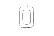
- the wound iron core 20 shown in FIG. 8 has a configuration in which a plurality of iron core members 20a obtained by cutting a silicon steel plate (not shown) are wound.
- the wound iron core 20 has a substantially rectangular window 21 at the center.
- the wound iron core 20 has four corner portions 22 provided at the four corners of the window portion 21 and four side portions 23 excluding these corner portions 22.
- the side portion 23 connects the corner portions 22.
- the side portion 23 includes a long side portion 23a to which a winding (not shown) is assembled, and a short side portion 23b shorter than the long side portion 23a.
- the iron core material 20a constituting the wound iron core 20 is cut from the silicon steel plate for one turn, that is, one turn, and in this case, has one cut portion for each turn.
- the junction part 24 is formed in the part to which a cutting part is joined in each iron core material 20a, ie, the both ends of each iron core material 20a.
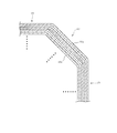
- the space factor of the iron core material 20 a in the corner portion 22 is lower than the space factor of the iron core material 20 a in the side portion 23. That is, the iron core material 20a is densely laminated at the side portion 23, but the iron core material 20a is not densely laminated at the corner portion 22, and there is a gap between the iron core materials 20a. In this case, each iron core material 20a has a gap for each sheet.
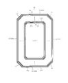
- the length La2 of the portion forming the side portion 23 in the iron core material 20 a 2 is the same as that in the iron core material 20 a 1 inside the iron core material 20 a 2. It is bent so as to be longer by a predetermined amount than the length La1 of the portion forming the side portion 23.
- the predetermined amount is “2 ⁇ ⁇ ”.
- the value of the predetermined amount ⁇ can be appropriately changed and set according to the target space factor of the corner portion 22 of the wound core 20.
- the length Lb2 of the portion forming the corner portion 22 in the iron core material 20a2 is larger than the length Lb1 of the portion forming the corner portion 22 in the iron core material 20a1 inside the iron core material 20a2. It is bent so as to be longer by a fixed amount.
- the predetermined amount is “2 ⁇ ⁇ ”. Note that the value of the predetermined amount ⁇ can be appropriately changed and set according to the target space factor of the corner portion 22 of the wound core 20.
- the wound core 20 is also configured by forming core groups 25a, 25b,... For each predetermined number of cores 20a. That is, each time a predetermined number of core members 20a are stacked from the inside, one core member group 25a, 25b,... Is formed. Moreover, the iron core material 20a included in each iron core material group 25a, 25b,... Is wound so that the joint portions 24 to which the cut portions are joined are shifted in the circumferential direction and positioned in a stepped manner. .
- the position Pb of the joint portion 24 of the iron core material 20a wound on the innermost side in the iron core material group 25b is the iron core wound on the innermost side in the iron core material group 25a adjacent to the inner side of the iron core material group 25b. It almost or completely coincides with the position Pa of the joint portion 24 of the material group 25a.
- the circumferential length Lb of the iron core material 20a wound on the innermost side in the iron core material group 25b is the circumference of the iron core material 20a wound on the outermost side in the iron core material group 25a adjacent to the inner side of the iron core material group 25b. It is larger than the length La.
- This manufacturing method includes a bending process of a silicon steel sheet, a cutting process of the silicon steel sheet, a lamination process of a core material, a forming process of a wound core, and an annealing process of the wound core.
- a manufacturing apparatus (not shown) is configured to sequentially feed silicon steel strips with a feeder. Then, one turn, that is, one turn of the iron core material 20a is sequentially cut by a cutting blade from the silicon steel strips that are sequentially fed.
- a manufacturing apparatus (not shown) appropriately folds the core material 20a that is sequentially fed by a folding machine.
- the iron core material 20a bent at an appropriate position is sequentially obtained.
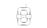
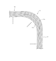
- Step 2 the folded iron core material 20a obtained from the silicon steel strip is sequentially laminated. At this time, as shown in FIG. 9, for example, a gap is formed between the iron core members 20 a in the portion that becomes the corner portion 22. In this laminating step, the iron core members 20a do not need to be densely laminated, but may be loosely laminated as a whole, including the folded portion and the unfolded portion.
- the molds 104 and 105 are applied to the four inner portions and the four outer portions of the plurality of stacked iron core members 20 a. And the four places of the iron core material 20a are suitably pressed along the lamination direction by the molds 104 and 105. In addition, a press is performed in the state which joined the cutting part of each iron core material 20a. By appropriately pressing the four places of the iron core material 20a, the side portion 23 is formed in the pressed portion, and the corner portion 22 is formed in the other portion, that is, the portion that is not pressed.
- the portions can absorb the deformation of the iron core materials 20a accompanying the press. Therefore, it can prevent that the cutting part of each iron core material 20a, ie, the junction part 24, opens after pressing.
- the junction part 24 is set so that it may be located in the short side part 23b. That is, each iron core material 20a is pressed in a state in which a portion forming the joint portion 24 is sandwiched between the short-side molds 104b and 105b.
- each iron core material 20a which constitutes wound iron core 20 is cooled after being heated to a predetermined temperature of about 800 ° C., for example.
- a predetermined temperature of about 800 ° C. for example.
- each core material 20a may be slightly deformed as the residual stress is eliminated. However, even if such deformation occurs, the deformation is absorbed by appropriately deforming the corner portion 22 having a low space factor. Therefore, it is possible to prevent the joint portion 24 from being opened by this annealing process.
- the wound core 20 in which the space factor of the iron core material 20a in the corner portion 22 is lower than the space factor of the iron core material 20a in the side portion 23 is manufactured.
- the joint portions 24 formed by the respective core members 20 a are hardly or not open, and the gap is not generated at all in the joint portions 24.
- this winding assembling step first, the wound core 20 is once opened with the cut portion of each core member 20a, in other words, the joint 24 as a boundary. And the coil
- the space factor of the iron core material in the corner portion is lower than the space factor of the iron core material in the side portion excluding the corner portion. Therefore, for example, even when the core material 20a is deformed when the wound core 20 is molded or tightened, the deformation can be absorbed by the corner portion, and the joint portion 24 can be prevented from opening. . Therefore, it is possible to manufacture the favorable wound core 20 in which the joint portion 24 is closed without performing precise dimensional management in each manufacturing process. Further, for example, a winding core tightening step after the winding is assembled can be omitted, and the wound core 20 can be manufactured without increasing the number of manufacturing steps. Moreover, since it can prevent that the junction part 24 opens in the wound core 20 manufactured, the increase in a core loss can be suppressed.
- the wound core 20 forms the core group 25a, 25b,... For each predetermined number of cores 20a.
- the core material 20 a included in each of the core material groups 25 a, 25 b,... Is positioned so that the joints 24 to which the cut parts are joined are shifted in the circumferential direction and are stepped. It is wound.
- the position of the joint portion 24 of the iron core material 20 a wound on the innermost side in one iron core material group is wound on the innermost side in the iron core material group adjacent to the inner side of the iron core material group.
- the position of the joint 24 of the iron core material 20a is completely or substantially coincident.
- the wound core 20 is configured such that the portion where the joint 24 is formed is shifted stepwise in the circumferential direction.
- the joint part 24 in which the magnetic resistance of the magnetic path is relatively large can be sequentially shifted along the circumferential direction, and the flow of magnetic flux in the wound core 10 can be made smooth.
- the wound core 20 has the outer circumference of the iron core material group adjacent to the inner side of the iron core material group in which the circumference of the iron core material 20a wound at the innermost side in one iron core material group is the outermost. It was comprised so that it might become larger than the perimeter of the iron core material 20a wound by. Thereby, the space factor of the corner part 22 can be made low reliably. Moreover, the space factor of the corner part 22 can be quantitatively lowered by appropriately adjusting the circumference of each iron core material 20a.
- the core material 20a that has one cut portion for each turn and in which a portion that forms the corner portion 22 is folded in advance is loosely laminated.
- the rectangular window portion 21 is formed at the center in a state where the cut portions of the iron core members 20a are joined.
- the length of the portion forming the side portion in one iron core material is set longer than the length of the portion forming the side portion in the iron core material inside the iron core material.
- the wound core 20 in which the space factor of the iron core material 20a in the corner portion 22 is lower than the space factor of the iron core material 20a in the side portion 13 excluding the corner portion 22 is stably manufactured. Can do.
- the wound iron core according to the embodiment described above is a wound iron core in which a plurality of iron core materials each having at least one cut portion are wound for each turn and having a rectangular window portion at the center, and a corner portion.
- the space factor of the iron core material is lower than the space factor of the iron core material in the side portion excluding the corner portion.
- the manufacturing method of the wound core which concerns on embodiment described above is the state which wound the several core material which has a cutting part of at least 1 place for every volume loosely, and joined the said cutting part of each iron core material By forming a rectangular window at the center, a wound core in which the space factor of the iron core material in the corner portion is lower than the space factor of the iron core material in the side portion excluding the corner portion is manufactured. .
- the method for manufacturing a wound core includes loosely laminating an iron core material that has at least one cut portion for each turn, and a portion that forms a corner portion is bent in advance.
- the space factor of the iron core material in the corner portion is such that the iron core material is occupied in the side portions other than the corner portion.
- the length of the portion forming the side portion in the iron core material is determined by the length of the iron core material.
- the inner core material is bent so as to be a predetermined amount longer than the length of the portion that forms the side portion, and the length of the portion that forms the corner portion of the one iron core material is set to the inside of the core material.
- the corner The length of the forming part bent so that a predetermined amount longer than.
- the iron core material is not limited to one having one cut portion per turn, and may have a plurality of cut portions per turn. That is, the iron core material is included in the technical idea according to the present embodiment as long as it has at least one cut portion for each roll.
- the wound core 10 may have a configuration in which each of the core members 10 a in the corner portion 12 has a gap for each of a plurality of sheets.
- the wound core 20 may have a configuration in which each of the core members 20 a in the corner portion 22 has a gap for every plurality.
- the number of the iron core material 10a or the iron core material 20a existing between the gaps can be changed as appropriate.
- the above-described iron core material group can have a gap.
- the wound core may have a configuration in which a region in which each iron core material has a gap for each sheet and a region in which each iron core material has a gap for every plurality of sheets are mixed in the corner portion.
- 10 is a wound core
- 11 is a window
- 12 is a corner
- 13 is a side
- 14 is a joint
- 20 is a wound core
- 21 is a window
- 22 is a corner
- 23 is a side
- 24 is The joint is shown.
Landscapes
- Engineering & Computer Science (AREA)
- Power Engineering (AREA)
- Manufacturing & Machinery (AREA)
- Manufacturing Cores, Coils, And Magnets (AREA)
Abstract
Description
例えば図1に示す巻鉄心10は、図示しない珪素鋼板を切断することにより得られた複数枚の鉄心材10aが巻回された構成である。この巻鉄心10は、中心にほぼ矩形の窓部11を有する。また、巻鉄心10は、窓部11の4隅に設けられる4つのコーナ部12と、これらコーナ部12を除く4つの辺部13を有する。辺部13は、コーナ部12間を繋ぐ。この場合、辺部13は、図示しない巻線が組み付けられる長辺部13aと、この長辺部13aよりも短い短辺部13bからなる。巻鉄心10を構成する複数枚の鉄心材10aは、一巻き分、つまりワンターン分ごとに珪素鋼板から切断されたものであり、従って、この場合、一巻ごとに1箇所の切断部を有している。そして、各鉄心材10aにおいて切断部が接合される部分、つまり、各鉄心材10aの両端部には接合部14が形成される。
Lb=La+πd+α・・・・・(1)
この工程では、例えば図5に示すように、製造装置100は、珪素鋼帯Mをフィーダ101によって順次送る構成である。そして、製造装置100は、順次送られる珪素鋼帯Mから、一巻き分、つまりワンターン分の鉄心材10aを切断刃102により順次切断する。
この工程では、例えば図5に示すように、製造装置100は、珪素鋼帯Mから得られた鉄心材10aを、円形の巻き取り型103に順次巻き取る。このとき、各鉄心材10aは、従来よりも緩く巻回される。なお、鉄心材10aを緩める程度は、目標とする巻鉄心10のコーナ部12の占積率に応じて、適宜調整して実施することができる。即ち、鉄心材10aを緩める程度を大きくするほど、コーナ部12の占積率をより低くすることができる。
この工程では、例えば図6に示すように、巻き取られ積層された複数枚の鉄心材10aの内側の4箇所と外側の4箇所に成形型104,105を当てる。そして、成形型104,105により、鉄心材10aの4箇所を積層方向に沿って適宜プレスする。なお、プレスは、各鉄心材10aの切断部を接合した状態で行われる。鉄心材10aの4箇所が適宜プレスされることにより、プレスされる部分つまり成形型104,105によって挟まれた部分にそれぞれ辺部13が形成され、それ以外の部分、つまり、プレスされない部分にそれぞれコーナ部12が形成される。なお、「プレスされない部分」とは、換言すれば、成形型104,105によって挟まれていない部分である。
この工程では、巻鉄心10を、例えば約800℃ほどの所定温度に加熱した後に冷却する。これにより、巻鉄心10を構成する各鉄心材10aに生じている残留応力を緩和することができ、残留応力に起因して巻鉄心10の鉄損特性が悪化してしまうことを回避することができる。なお、残留応力が解消されることに伴い各鉄心材10aが若干変形する場合がある。しかし、このような変形が生じたとしても、その変形は、占積率が低いコーナ部12が適宜変形することにより吸収される。よって、この焼鈍工程により接合部14が開いてしまうことも防止される。
例えば図8に示す巻鉄心20は、図示しない珪素鋼板を切断することにより得られた複数枚の鉄心材20aが巻回された構成である。この巻鉄心20は、中心にほぼ矩形の窓部21を有する。また、巻鉄心20は、窓部21の4隅に設けられる4つのコーナ部22と、これらコーナ部22を除く4つの辺部23を有する。辺部23は、コーナ部22間を繋ぐ。この場合、辺部23は、図示しない巻線が組み付けられる長辺部23aと、この長辺部23aよりも短い短辺部23bからなる。巻鉄心20を構成する鉄心材20aは、一巻き分、つまりワンターン分ごとに珪素鋼板から切断されたものであり、従って、この場合、一巻ごとに1箇所の切断部を有している。そして、各鉄心材20aにおいて切断部が接合される部分、つまり、各鉄心材20aの両端部には接合部24が形成される。
この工程では、図示しない製造装置は、珪素鋼帯をフィーダによって順次送る構成である。そして、順次送られる珪素鋼帯から、一巻き分、つまりワンターン分の鉄心材20aを切断刃により順次切断する。
この工程では、図示しない製造装置は、順次送られる鉄心材20aを折り曲げ機によって適宜折り曲げる。このときの折り曲げ位置を適宜調整して設定することにより、例えば図10に示したように、適宜の位置にて折り曲げられた鉄心材20aが順次得られる。なお、珪素鋼帯を所定位置にて順次折り曲げる折り曲げ工程を行った後に、その珪素鋼帯をワンターン分ごとに切断する切断工程を行うように構成してもよい。
この工程では、珪素鋼帯から得られた折り曲げ済みの鉄心材20aを順次積層する。このとき、例えば図9に示したように、コーナ部22となる部分における各鉄心材20a間には隙間が形成された状態となる。なお、この積層工程においては、各鉄心材20aを密に積層する必要はなく、折り曲げられた部分、さらには折り曲げられていない部分も含めて全体的に緩く積層すればよい。
この工程では、例えば図11に示すように、積層された複数枚の鉄心材20aの内側の4箇所と外側の4箇所に成形型104,105を当てる。そして、成形型104,105により、鉄心材20aの4箇所を積層方向に沿って適宜プレスする。なお、プレスは、各鉄心材20aの切断部を接合した状態で行われる。鉄心材20aの4箇所が適宜プレスされることにより、プレスされる部分に辺部23が形成され、それ以外の部分、つまり、プレスされない部分にコーナ部22が形成される。このとき、コーナ部22となる部分における各鉄心材20a間には隙間が形成されていることから、当該部分により、プレスに伴う鉄心材20aの変形を吸収することができる。よって、プレス後に、各鉄心材20aの切断部、換言すれば接合部24が開いてしまうことを防止することができる。なお、接合部24は、短辺部23bに位置して形成されるように設定されている。即ち、各鉄心材20aは、接合部24を形成する部分が短辺成形型104b,105bの間に挟まれた状態でプレスされる。
この工程では、巻鉄心20を、例えば約800℃ほどの所定温度に加熱した後に冷却する。これにより、巻鉄心20を構成する各鉄心材20aに生じている残留応力を緩和することができ、残留応力に起因して巻鉄心20の鉄損特性が悪化してしまうことを回避することができる。なお、残留応力が解消されることに伴い各鉄心材20aが若干変形する場合がある。しかし、このような変形が生じたとしても、その変形は、占積率が低いコーナ部22が適宜変形することにより吸収される。よって、この焼鈍工程により接合部24が開いてしまうことも防止される。
Claims (7)
- 一巻ごとに少なくとも1箇所の切断部を有する複数枚の鉄心材が巻回され、中心に矩形の窓部を有する巻鉄心であって、
前記窓部の4隅に設けられるコーナ部と、前記コーナ部間を繋ぐ辺部と、を有し、
前記コーナ部における前記鉄心材の占積率が前記辺部における前記鉄心材の占積率よりも低い巻鉄心。 - 所定枚の前記鉄心材ごとに複数の鉄心材群が形成され、
各鉄心材群に含まれる前記鉄心材は、前記切断部が接合される接合部が相互に周方向にずれて階段状に位置するように巻回され、
前記鉄心材群において最も内側で巻回される前記鉄心材の前記接合部の位置は、当該鉄心材群の内側の鉄心材群において最も内側で巻回される前記鉄心材の前記接合部の位置と一致し、
前記鉄心材群において最も内側で巻回される前記鉄心材の周長は、当該鉄心材群の内側の鉄心材群において最も外側で巻回される前記鉄心材の周長よりも大きい請求項1に記載の巻鉄心。 - 前記鉄心材は、前記コーナ部を形成する部分が折り曲げられており、
前記鉄心材において前記辺部を形成する部分は、当該鉄心材の内側の鉄心材において前記辺部を形成する部分よりも長く、
前記鉄心材において前記コーナ部を形成する部分は、当該鉄心材の内側の鉄心材において前記コーナ部を形成する部分よりも長い請求項1または2に記載の巻鉄心。 - 前記鉄心材は、前記コーナ部において1枚毎に隙間を有する請求項1から3の何れか1項に記載の巻鉄心。
- 前記鉄心材は、前記コーナ部において複数枚毎に隙間を有する請求項1から4の何れか1項に記載の巻鉄心。
- 一巻ごとに少なくとも1箇所の切断部を有する複数枚の鉄心材を緩く巻回し、各鉄心材の前記切断部を接合した状態で中心に矩形の窓部を形成することにより、コーナ部における前記鉄心材の占積率が辺部における前記鉄心材の占積率よりも低い巻鉄心を製造する巻鉄心の製造方法。
- 一巻ごとに少なくとも1箇所の切断部を有し、且つ、コーナ部を形成する部分が予め折り曲げられた鉄心材を積層し、各鉄心材の前記切断部を接合した状態で中心に矩形の窓部を形成することにより、前記コーナ部における前記鉄心材の占積率が辺部における前記鉄心材の占積率よりも低い巻鉄心を製造する方法であって、
前記鉄心材を積層する前に折り曲げることにより、
前記鉄心材において前記辺部を形成する部分を、当該鉄心材の内側の鉄心材において前記辺部を形成する部分よりも長くし、且つ、
前記鉄心材において前記コーナ部を形成する部分を、当該鉄心材の内側の鉄心材において前記コーナ部を形成する部分よりも長くする巻鉄心の製造方法。
Priority Applications (4)
| Application Number | Priority Date | Filing Date | Title |
|---|---|---|---|
| AU2014379890A AU2014379890B2 (en) | 2014-01-27 | 2014-12-11 | Wound core and method for manufacturing wound core |
| CN201480069007.7A CN105830180A (zh) | 2014-01-27 | 2014-12-11 | 卷铁芯及卷铁芯的制造方法 |
| EP14879793.9A EP3101667B1 (en) | 2014-01-27 | 2014-12-11 | Wound core and method for manufacturing wound core |
| US15/221,259 US20160336100A1 (en) | 2014-01-27 | 2016-07-27 | Wound core and method for manufacturing wound core |
Applications Claiming Priority (2)
| Application Number | Priority Date | Filing Date | Title |
|---|---|---|---|
| JP2014012416A JP6224468B2 (ja) | 2014-01-27 | 2014-01-27 | 巻鉄心および巻鉄心の製造方法 |
| JP2014-012416 | 2014-01-27 |
Related Child Applications (1)
| Application Number | Title | Priority Date | Filing Date |
|---|---|---|---|
| US15/221,259 Continuation US20160336100A1 (en) | 2014-01-27 | 2016-07-27 | Wound core and method for manufacturing wound core |
Publications (1)
| Publication Number | Publication Date |
|---|---|
| WO2015111320A1 true WO2015111320A1 (ja) | 2015-07-30 |
Family
ID=53681140
Family Applications (1)
| Application Number | Title | Priority Date | Filing Date |
|---|---|---|---|
| PCT/JP2014/082841 Ceased WO2015111320A1 (ja) | 2014-01-27 | 2014-12-11 | 巻鉄心及び巻鉄心の製造方法 |
Country Status (6)
| Country | Link |
|---|---|
| US (1) | US20160336100A1 (ja) |
| EP (1) | EP3101667B1 (ja) |
| JP (1) | JP6224468B2 (ja) |
| CN (1) | CN105830180A (ja) |
| AU (1) | AU2014379890B2 (ja) |
| WO (1) | WO2015111320A1 (ja) |
Cited By (1)
| Publication number | Priority date | Publication date | Assignee | Title |
|---|---|---|---|---|
| US20220351890A1 (en) * | 2019-09-03 | 2022-11-03 | Nippon Steel Corporation | Wound core |
Families Citing this family (24)
| Publication number | Priority date | Publication date | Assignee | Title |
|---|---|---|---|---|
| JP6506000B2 (ja) * | 2014-07-11 | 2019-04-24 | 東芝産業機器システム株式会社 | 巻鉄心および巻鉄心の製造方法 |
| JP2017054962A (ja) * | 2015-09-10 | 2017-03-16 | 東芝産業機器システム株式会社 | 巻鉄心の製造方法および巻鉄心の製造装置 |
| JP6784520B2 (ja) * | 2016-06-24 | 2020-11-11 | 東芝産業機器システム株式会社 | 鉄心、鉄心の製造方法、鉄心の製造装置 |
| JP6517882B2 (ja) * | 2017-07-04 | 2019-05-22 | ファナック株式会社 | コア本体およびリアクトル |
| CN107327487A (zh) * | 2017-08-29 | 2017-11-07 | 南京磁谷科技有限公司 | 一种倾斜磁极磁轴承的u形磁极结构 |
| KR102569980B1 (ko) * | 2017-09-11 | 2023-08-24 | 가부시끼가이샤 레조낙 | 회로 접속용 접착제 필름 및 그의 제조 방법, 회로 접속 구조체의 제조 방법, 그리고 접착제 필름 수용 세트 |
| RU2761552C1 (ru) * | 2018-10-02 | 2021-12-09 | Ниппон Стил Корпорейшн | Магнитный сердечник |
| PL4030447T3 (pl) * | 2019-09-10 | 2025-10-06 | Nippon Steel Corporation | Rdzeń nawijany |
| WO2022092112A1 (ja) | 2020-10-26 | 2022-05-05 | 日本製鉄株式会社 | 巻鉄心 |
| CN116457478A (zh) | 2020-10-26 | 2023-07-18 | 日本制铁株式会社 | 卷绕铁芯 |
| JP7193047B2 (ja) | 2020-10-26 | 2022-12-20 | 日本製鉄株式会社 | 巻鉄心、巻鉄心の製造方法及び巻鉄心製造装置 |
| JP7107470B1 (ja) | 2020-10-26 | 2022-07-27 | 日本製鉄株式会社 | 巻鉄心、巻鉄心の製造方法及び巻鉄心製造装置 |
| JP7538440B2 (ja) | 2020-10-26 | 2024-08-22 | 日本製鉄株式会社 | 巻鉄心 |
| HRP20250158T1 (hr) | 2020-10-26 | 2025-03-28 | Nippon Steel Corporation | Namotana jezgra, postupak proizvodnje namotane jezgre, te uređaj za proizvodnju namotane jezgre |
| PL4235718T3 (pl) | 2020-10-26 | 2025-03-24 | Nippon Steel Corporation | Sposób i urządzenie do wytwarzania rdzenia żelaznego zwijanego |
| WO2022092120A1 (ja) | 2020-10-26 | 2022-05-05 | 日本製鉄株式会社 | 巻鉄心 |
| JP7695546B2 (ja) * | 2020-10-26 | 2025-06-19 | 日本製鉄株式会社 | 巻鉄心 |
| US20230386727A1 (en) * | 2020-10-26 | 2023-11-30 | Nippon Steel Corporation | Wound core |
| TWI777830B (zh) | 2020-10-26 | 2022-09-11 | 日商日本製鐵股份有限公司 | 捲鐵心 |
| RS66831B1 (sr) | 2020-10-26 | 2025-06-30 | Nippon Steel Corp | Gvozdeno jezgro sa namotajima, metoda za proizvodnju gvozdenog jezgra sa namotajima i oprema za proizvodnju gvozdenog jezgra sa namotajima |
| WO2023058655A1 (ja) | 2021-10-04 | 2023-04-13 | 日本製鉄株式会社 | 巻鉄心 |
| CN117897786B (zh) | 2021-10-04 | 2024-09-20 | 日本制铁株式会社 | 卷绕铁芯 |
| US20250364173A1 (en) | 2022-06-22 | 2025-11-27 | Nippon Steel Corporation | Wound core |
| TWI843613B (zh) | 2022-06-22 | 2024-05-21 | 日商日本製鐵股份有限公司 | 捲鐵心 |
Citations (3)
| Publication number | Priority date | Publication date | Assignee | Title |
|---|---|---|---|---|
| JPS61179517A (ja) * | 1985-02-04 | 1986-08-12 | Toshiba Corp | 静止誘導電器の製造方法 |
| JPH05159953A (ja) | 1991-12-09 | 1993-06-25 | Daihen Corp | 3相巻鉄心の製造方法 |
| JPH0645165A (ja) * | 1992-07-24 | 1994-02-18 | Takaoka Electric Mfg Co Ltd | 巻鉄心の製造方法 |
Family Cites Families (15)
| Publication number | Priority date | Publication date | Assignee | Title |
|---|---|---|---|---|
| GB653908A (en) * | 1947-04-30 | 1951-05-30 | Westinghouse Electric Int Co | Improvements in or relating to electric induction apparatus |
| US3223955A (en) * | 1961-11-13 | 1965-12-14 | Porter Co Inc H K | Transformer core construction and method of producing same |
| US3307132A (en) * | 1966-05-13 | 1967-02-28 | Westinghouse Electric Corp | Magnetic core having discrete bends at each corner |
| JPH0697646B2 (ja) * | 1985-07-11 | 1994-11-30 | 株式会社日立製作所 | 非晶質磁性合金巻鉄心 |
| JPS62210609A (ja) * | 1986-03-12 | 1987-09-16 | Toshiba Corp | 巻鉄心の製造方法 |
| JP2776337B2 (ja) * | 1995-10-24 | 1998-07-16 | 株式会社日立製作所 | 非晶質巻鉄心 |
| US7057489B2 (en) * | 1997-08-21 | 2006-06-06 | Metglas, Inc. | Segmented transformer core |
| SE0000410D0 (sv) * | 2000-02-06 | 2000-02-06 | Lennart Hoeglund | Trefas transformatorkärna |
| CN2901516Y (zh) * | 2006-01-05 | 2007-05-16 | 刘建南 | 一种改进结构的卷绕式铁芯 |
| JP5843124B2 (ja) * | 2009-11-17 | 2016-01-13 | 日立金属株式会社 | コアの製造方法 |
| CN101819859A (zh) * | 2010-05-25 | 2010-09-01 | 威海凯迪帕沃开关有限公司 | 壳式变压器用卷铁芯及方法 |
| CN102208264A (zh) * | 2010-11-08 | 2011-10-05 | 宁波新胜中压电器有限公司 | 10kV调容变压器 |
| CN202796351U (zh) * | 2012-09-07 | 2013-03-13 | 苏州安泰变压器有限公司 | 一种新型单相卷铁心配电变压器 |
| WO2016013327A1 (ja) * | 2014-07-23 | 2016-01-28 | ボッシュ株式会社 | 巻回体及び巻回体の製造方法 |
| USD771728S1 (en) * | 2014-08-18 | 2016-11-15 | Tokuden Co., Ltd. | Three-leg iron core |
-
2014
- 2014-01-27 JP JP2014012416A patent/JP6224468B2/ja active Active
- 2014-12-11 CN CN201480069007.7A patent/CN105830180A/zh active Pending
- 2014-12-11 AU AU2014379890A patent/AU2014379890B2/en active Active
- 2014-12-11 WO PCT/JP2014/082841 patent/WO2015111320A1/ja not_active Ceased
- 2014-12-11 EP EP14879793.9A patent/EP3101667B1/en active Active
-
2016
- 2016-07-27 US US15/221,259 patent/US20160336100A1/en not_active Abandoned
Patent Citations (3)
| Publication number | Priority date | Publication date | Assignee | Title |
|---|---|---|---|---|
| JPS61179517A (ja) * | 1985-02-04 | 1986-08-12 | Toshiba Corp | 静止誘導電器の製造方法 |
| JPH05159953A (ja) | 1991-12-09 | 1993-06-25 | Daihen Corp | 3相巻鉄心の製造方法 |
| JPH0645165A (ja) * | 1992-07-24 | 1994-02-18 | Takaoka Electric Mfg Co Ltd | 巻鉄心の製造方法 |
Non-Patent Citations (1)
| Title |
|---|
| See also references of EP3101667A4 |
Cited By (2)
| Publication number | Priority date | Publication date | Assignee | Title |
|---|---|---|---|---|
| US20220351890A1 (en) * | 2019-09-03 | 2022-11-03 | Nippon Steel Corporation | Wound core |
| US12500027B2 (en) * | 2019-09-03 | 2025-12-16 | Nippon Steel Corporation | Wound core |
Also Published As
| Publication number | Publication date |
|---|---|
| JP6224468B2 (ja) | 2017-11-01 |
| EP3101667B1 (en) | 2019-12-04 |
| AU2014379890B2 (en) | 2018-04-05 |
| CN105830180A (zh) | 2016-08-03 |
| AU2014379890A1 (en) | 2016-08-25 |
| EP3101667A4 (en) | 2017-06-28 |
| EP3101667A1 (en) | 2016-12-07 |
| US20160336100A1 (en) | 2016-11-17 |
| JP2015141930A (ja) | 2015-08-03 |
Similar Documents
| Publication | Publication Date | Title |
|---|---|---|
| JP6224468B2 (ja) | 巻鉄心および巻鉄心の製造方法 | |
| US7057489B2 (en) | Segmented transformer core | |
| US20130328652A1 (en) | Three-step core for a non-linear transformer | |
| WO2011061803A1 (ja) | 回転電機のモールドステータの製造方法 | |
| CN108028130A (zh) | 卷铁心的制造方法以及卷铁心的制造装置 | |
| US20130147596A1 (en) | Reactor Device | |
| JP2012134448A (ja) | アモルファス材を使用したリアクトル装置及びその製造方法 | |
| JP5390869B2 (ja) | 積層鉄心及びその製造方法 | |
| JP6466728B2 (ja) | 変圧器およびその製造方法 | |
| KR101481057B1 (ko) | 유전위 컴팩트 주상변압기 제조방법 | |
| JP5329059B2 (ja) | ステータおよびステータの製造方法 | |
| JP2007267585A (ja) | 積層鉄心及びその製造方法 | |
| US3267557A (en) | Method of making a laminated core | |
| JP7032257B2 (ja) | 変圧器および積鉄心 | |
| JPS6328589Y2 (ja) | ||
| JP2018160502A (ja) | 巻鉄心の製造方法 | |
| JP6269335B2 (ja) | 回転電機の固定子鉄心およびその製造方法 | |
| JP5306796B2 (ja) | アウターロータ型モータ用積層鉄心及びその製造方法 | |
| JPS5967615A (ja) | 変圧器の組立方法 | |
| JP7329961B2 (ja) | 鉄心部材の熱処理方法、熱処理用治具 | |
| WO2019123513A1 (ja) | 固定子鉄心及びその固定子鉄心を備えた電動機 | |
| CN115133678A (zh) | 定子组件及其制作方法、电机 | |
| JP6605425B2 (ja) | アモルファス変圧器およびその製造方法 | |
| JPS59178716A (ja) | 積層鉄心の製造方法 | |
| JPS58101412A (ja) | 巻鉄心型変圧器の製造方法 |
Legal Events
| Date | Code | Title | Description |
|---|---|---|---|
| 121 | Ep: the epo has been informed by wipo that ep was designated in this application |
Ref document number: 14879793 Country of ref document: EP Kind code of ref document: A1 |
|
| REG | Reference to national code |
Ref country code: BR Ref legal event code: B01A Ref document number: 112016016024 Country of ref document: BR |
|
| NENP | Non-entry into the national phase |
Ref country code: DE |
|
| REEP | Request for entry into the european phase |
Ref document number: 2014879793 Country of ref document: EP |
|
| WWE | Wipo information: entry into national phase |
Ref document number: 2014879793 Country of ref document: EP |
|
| ENP | Entry into the national phase |
Ref document number: 2014379890 Country of ref document: AU Date of ref document: 20141211 Kind code of ref document: A |
|
| ENP | Entry into the national phase |
Ref document number: 112016016024 Country of ref document: BR Kind code of ref document: A2 Effective date: 20160708 |