WO2015114875A1 - Endoscope - Google Patents
Endoscope Download PDFInfo
- Publication number
- WO2015114875A1 WO2015114875A1 PCT/JP2014/074224 JP2014074224W WO2015114875A1 WO 2015114875 A1 WO2015114875 A1 WO 2015114875A1 JP 2014074224 W JP2014074224 W JP 2014074224W WO 2015114875 A1 WO2015114875 A1 WO 2015114875A1
- Authority
- WO
- WIPO (PCT)
- Prior art keywords
- long
- elastic member
- cable
- bending
- locking member
- Prior art date
- Legal status (The legal status is an assumption and is not a legal conclusion. Google has not performed a legal analysis and makes no representation as to the accuracy of the status listed.)
- Ceased
Links
Images



Classifications
-
- A—HUMAN NECESSITIES
- A61—MEDICAL OR VETERINARY SCIENCE; HYGIENE
- A61B—DIAGNOSIS; SURGERY; IDENTIFICATION
- A61B1/00—Instruments for performing medical examinations of the interior of cavities or tubes of the body by visual or photographical inspection, e.g. endoscopes; Illuminating arrangements therefor
- A61B1/005—Flexible endoscopes
- A61B1/0051—Flexible endoscopes with controlled bending of insertion part
- A61B1/0057—Constructional details of force transmission elements, e.g. control wires
-
- A—HUMAN NECESSITIES
- A61—MEDICAL OR VETERINARY SCIENCE; HYGIENE
- A61B—DIAGNOSIS; SURGERY; IDENTIFICATION
- A61B1/00—Instruments for performing medical examinations of the interior of cavities or tubes of the body by visual or photographical inspection, e.g. endoscopes; Illuminating arrangements therefor
- A61B1/005—Flexible endoscopes
- A61B1/0051—Flexible endoscopes with controlled bending of insertion part
- A61B1/0052—Constructional details of control elements, e.g. handles
-
- G—PHYSICS
- G02—OPTICS
- G02B—OPTICAL ELEMENTS, SYSTEMS OR APPARATUS
- G02B23/00—Telescopes, e.g. binoculars; Periscopes; Instruments for viewing the inside of hollow bodies; Viewfinders; Optical aiming or sighting devices
- G02B23/24—Instruments or systems for viewing the inside of hollow bodies, e.g. fibrescopes
- G02B23/2476—Non-optical details, e.g. housings, mountings, supports
Definitions
- the present invention relates to an endoscope including a flexible long member disposed in an insertion portion and extending into an operation portion.
- Some endoscopes include a bendable bending portion on the distal end side of the insertion portion so that the direction of the distal end where the objective lens is disposed can be changed without changing the insertion position.
- Such an endoscope includes, for example, a bending wire extending from the operation unit to the insertion unit, and the driving force of the bending operation generated in the operation unit is transmitted through the bending wire, so that the bending unit is bent. Is to be done.
- an endoscope described in Japanese Patent Laid-Open No. 8-160317 can be cited.
- This endoscope includes a main body having an operation mechanism, and a flexible insertion portion, a bendable bending portion, and a rigid tip that are connected to the main body.
- the rear end of a wire for bending the bending portion is connected to the slider of the operation mechanism, and this wire is inserted through the insertion portion and the bending portion, and the tip is fixed to the hard tip.
- a support plate is provided on the front end side of the slider in the body, and a compression coil spring is interposed between the support plate and the slider so as to surround the wire.
- the force of the coil spring is sufficient to eliminate the slack of the wire, and is not so strong as to hinder the bending operation of the bending portion.
- Japanese Patent Application Laid-Open No. 11-295616 discloses an optically driven actuator used, for example, for swinging the tip swing portion of an endoscope for observing the inside of a body or a thin tube through a swing wire. Is described.
- This light-driven actuator includes a shape memory spring portion and a bias spring portion arranged with a movable portion that can move linearly, and a heating optical fiber that irradiates and heats the shape memory spring portion. Yes.
- the endoscope is a flexible long member that is disposed in the insertion portion and extends into the operation portion, and a light guide that transmits illumination light for illuminating the subject (or the distal end portion of the endoscope).
- Illumination cable for transmitting illumination power for emitting light from the arranged illumination element for example, a plurality of imaging cables connected to an imaging unit including the imaging element, a channel for inserting a treatment instrument, etc. It may be further provided in accordance with the function of the endoscope.
- the long member moves forward and backward in the central axis direction of the insertion portion inside the endoscope (in particular, inside the bending portion), but the filling rate of the built-in objects is high.
- the frictional force is generated between the long members, and when the long member has a small diameter, the waist is weak and easy to bend.
- meandering occurs. If another long member enters the space generated by the meander so as to cross the long member where the meander has occurred, the arrangement of the plurality of long members is changed. When such an arrangement of the long member is disturbed, depending on the arrangement state, the movement of the long member is hindered during subsequent bending, or the long member is crossed between the long members. It is possible that damage will occur. Therefore, it is desired to suppress such disturbance of the arrangement of the long members as much as possible.
- the technique described in the above Japanese Patent Laid-Open No. 8-160317 is a technique for pulling a wire for pulling a hard tip with a coil spring, that is, a technique for a wire originally having a tensile strength. Therefore, even if the wire was always energized, there was no problem, but the above-described imaging cable, light guide, lighting cable, channel, etc. are not long members that are assumed to be pulled. Therefore, even if the technique described in the publication is applied as it is, the fatigue of the long member may be increased.
- the present invention has been made in view of the above circumstances, and provides an endoscope capable of suppressing disturbance of the arrangement of the long member of the insertion portion due to a bending operation while reducing fatigue of the long member as much as possible.
- the purpose is that.
- An endoscope is provided with a long insertion portion having a bendable bending portion, an operation portion connected to a proximal end side of the insertion portion, and the insertion portion.
- a flexible elongate member extending into the operation unit, one end side of the elongate member, and the other end side of the operation unit are engaged with each other, and the long member and the operation unit are relatively
- An elastic member that exerts an urging force that pulls the long member to the operation unit side in a size according to a position, and the long member is a section of the insertion unit perpendicular to the central axis of the insertion unit
- the elastic member is arranged in a natural state where the elastic member does not exert an urging force when the bending portion is bent in the direction in which the long member is arranged. Yes.
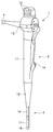
- FIG. 1 The perspective view which shows the endoscope in Embodiment 1 of this invention. Sectional drawing which shows the structure of the operation part of the endoscope in the said Embodiment 1.
- FIG. 1 the figure which shows the mode of a biasing mechanism when a curved part exists in a straight state.
- FIG. 1 is a perspective view showing an endoscope 1.
- an endoscope 1 is configured as an electronic endoscope, for example, and has a thin and long insertion portion 3 that is configured to be inserted into a subject, and the insertion portion 3.
- the operation unit 2 connected to the base end side of the control unit 2 and a universal cable 4 extending from the base end side of the operation unit 2 to the side are provided.
- the operation unit 2 is related to imaging such as a gripping unit 11 for an operator to grip, a bending lever 12 that can be bent by, for example, a thumb of a hand that holds the gripping unit 11, and a freeze operation, for example.
- An operation button 13 for performing the operation, a proximal end side opening of the channel 14 for inserting the treatment instrument, and a folding portion 15 for forming a tapered shape and preventing the insertion portion 3 from bending are provided.
- an operation unit main body 25 that is a framework of the operation unit 2 is provided inside the operation unit 2.
- the insertion portion 3 is, in order from the proximal end side to the distal end side, a long and flexible flexible tube portion 16, a bendable bending portion 17 that is bent by the operation of the bending lever 12 described above, An image pickup unit including an image pickup element, and a distal end rigid portion 18 provided with an objective optical system.
- the universal cable 4 includes a first cable 21, a second cable 22, and a third cable 23 that are connected to the imaging unit in the insertion unit 3, and a distal end of the insertion unit 3.
- a light guide 24 (see FIG. 7 of Embodiment 2 to be described later) for transmitting illumination light irradiated to the specimen is inserted, and the base end side thereof is connected to a video processor, a light source device or the like (not shown). belongs to.
- the flexible long member disposed in the insertion portion 3 and extending into the operation portion 2 is described above.
- the channel 14, the first cable 21, the second cable 22, the third cable 23, and the light guide 24 are provided.
- a bending wire for bending the bending portion 17 by pulling the distal end side of the bending portion 17 by operating the bending lever 12 is also disposed in the insertion portion 3 and extends into the operation portion 2.
- the first cable 21 that is a long member disposed in the down (D) direction is a down that curves the bending portion 17 in the D direction.
- the operation unit moves from the insertion unit 3 to the operation unit 2 side, and moves from the operation unit 2 to the insertion unit 3 side by an up operation of bending the bending unit 17 in the direction opposite to the D direction (up (U) direction shown in FIG. 7) To do.
- the first cable 21 is pulled into the operation unit 2 from the insertion portion 3 by an urging force of an elastic member 31 described later during a down operation, and is bent against the urging force of the elastic member 31 during an up operation.
- the wire is pulled out from the operation unit 2 to the insertion unit 3 by the pulling force of the wire.
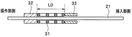
- At least one long member among the plurality of long members for example, as shown in FIG. 2, for example, the first cable 21, the elastic member 31, the first locking member 32, and the second member.
- An urging mechanism including a stop member 33 is provided.
- FIG. 3 is a diagram showing a state of the urging mechanism when the bending portion 17 is in a straight state
- FIG. 4 is a first cable that is a long member with the bending portion 17 bent in the up (U) direction
- FIG. 5 is a diagram showing a state of the urging mechanism when 21 is extended to the insertion portion 3 side
- FIG. 5 shows a first cable 21 that is a long member with the bending portion 17 bent in the down (D) direction.
- the elastic member 31 is engaged with the first cable 21, which is a long member, at one end side and the other end side with the operation unit 2, and is positioned at a relative position between the first cable 21 and the operation unit 2.
- the urging force for pulling the first cable 21 of the corresponding size toward the operation unit 2 is exhibited.
- the elastic member 31 is configured as a coil spring (for example, a compression coil spring), and is inserted outside the first cable 21.
- the elastic member 31 bends the bending portion 17 in the direction (down (D) direction shown in FIG. 7) in which the first cable 21 that is a long member is disposed in the cross section of the insertion portion 3 perpendicular to the central axis.
- the elastic member exerts an urging force in any curved state in order to prevent the long member from being bent regardless of the curved state of the curved portion 17.
- the urging force asymptotically approaches 0 at the time of at least one maximum bending. From such a viewpoint, it is preferable that the natural state of the elastic member 31 is achieved when the bending portion 17 is bent to the maximum in the direction (D direction) in which the long member is disposed.
- FIG. 5 shows a bent end state in which the bending portion 17 is bent to the maximum in the D direction (the first cable 21 is moved most toward the operation portion 2 along the central axis direction of the insertion portion 3). ) Shows a state where the elastic member 31 configured as a coil spring has a natural length L0 which is a natural state.
- the elastic member 31 since the elastic member 31 is compressed in a state other than the state shown in FIG. 5, the elastic member 31 is also in a straight state where the bending operation as shown in FIG. The urging
- the range that x satisfies is 0 ⁇ x ⁇ (L0 ⁇ Lmin).
- the spring constant of the elastic member 31 is k
- the first locking member 32 locks one end side of the elastic member 31 to the first cable 21 which is a long member. That is, the 1st locking member 32 is being fixed to the 1st cable 21 which is a long member, for example, by inserting a heat contraction tube outside the 1st cable 21, and contracting it by adding heat. It is a configured ring-shaped member.
- the outer diameter of the first locking member 32 when attached to the outer periphery of the first cable 21 is approximately the same as the outer diameter of the elastic member 31 configured as a coil spring. Accordingly, it is possible to suppress the increase in diameter of the operation unit 2 as much as possible while reliably locking the one end side of the elastic member 31.
- the second locking member 33 is configured as a ring-shaped member whose inner diameter is slightly larger than the outer diameter of the first cable 21 and whose outer diameter is approximately the same as the outer diameter of the elastic member 31. For example, it is fixed to the operation unit main body 25.
- the second locking member 33 guides the first cable 21 on the inner peripheral side, and locks the other end side of the elastic member 31 to the operation unit 2.
- the elastic member 31 exerts an urging force according to the distance between the first locking member 32 and the second locking member 33.
- the first cable 21 is taken as an example of the long member provided with the urging mechanism.
- the second cable 22 and the third cable 23 which are other cables, or the light guide 24 and the channel 14 are used.
- An urging mechanism may be provided on the bending wire or the like, but not limited thereto, any flexible member may be used as long as it is a flexible long member disposed in the insertion portion 3 and extending into the operation portion 2.
- An urging mechanism can be provided.
- the elastic member 31 exerts a biasing force that pulls the long member toward the operation unit 2, so that the long member moves smoothly, no meandering occurs, and insertion by a bending operation is performed. Disturbance of the arrangement of the long members of the portion 3 can be suppressed.
- the elastic member 31 is in a natural state in which it does not exert a biasing force, so at least the direction in which the long member is arranged.
- the bending portion 17 is bent in the opposite direction and in the straight state, that is, in a range that is more than half of the bendable range including the straight state considered to have the longest use time, the long member is pulled toward the operation portion 2 side.
- the elastic member 31 is further substantially in the entire bendable range. Disturbance of arrangement can be suppressed. Therefore, the elastic member 31 that exhibits a necessary and sufficient urging force can be employed, which can contribute to the downsizing of the endoscope 1.
- the elastic member 31 is directly attached to the long member or the operation unit 2. Even if it is not fixed, it is possible to secure an action point at which both ends of the elastic member 31 apply a biasing force.
- the elastic member 31 as a coil spring, the elastic member 31 can be arranged using the space on the outer peripheral side of the long member evenly, and the arrangement space of the elastic member 31 is biased in a specific direction. It does not occur, and there is an advantage that it is not necessary to change the shape of the operation unit 2.
- the 1st locking member 32 and the 2nd locking member 33 are comprised as a ring-shaped member, like the elastic member 31 at the time of using a coil spring, the space on the outer peripheral side of a long member is used. Since it is possible to arrange them evenly, there is an advantage that it is not necessary to change the shape of the operation unit 2. At this time, since the second locking member 33 guides the long member on the inner peripheral side, it is possible to smoothly promote the movement of the long member along the central axis direction of the insertion portion 3.
- FIG. 6 and 7 show Embodiment 2 of the present invention
- FIG. 6 is a cross-sectional view showing the configuration of the operation portion of the endoscope
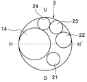
- FIG. 7 is an arrangement example of the built-in objects in the insertion portion of the endoscope.
- a plurality of urging mechanisms are provided for two or more of the plurality of long members.
- the long member group arranged on one end side and the long member group arranged on the other end side in a straight bending direction are collectively urged by one urging mechanism. Therefore, the number of urging mechanisms is two.
- the bending portion 17 is configured to be able to bend only in a straight line direction passing through the central axis of the insertion portion 3 in the cross section of the insertion portion 3 shown in FIG. Is curved only in two directions: one direction (referred to as the up (U) direction as shown in FIG. 7) and the opposite direction (also referred to as the down (D) direction). It is possible. These U direction and D direction are collectively referred to as a bendable direction as appropriate below.
- the arrangement of the built-in objects in the insertion section 3 is as shown in FIG. 7, and the channel 14, the first cable 21, the second cable 22, the third cable 23, and the light guide 24 are reversed in this order. Arranged clockwise.
- a dividing line that divides the insertion portion 3 into two, which is perpendicular to the bendable direction (U direction and D direction) and passes through the central axis of the insertion portion 3, is HH ′.
- Channel 14 is defined as a D region (first region) and a U region (second region) on the D direction side of the dividing line HH ′ of the two regions divided by For example, the channel centers are arranged on the dividing line HH ′.
- a plurality of other long members are separately provided in a first region and a second region, and the first cable 21 is connected to the D region (first region) in the second cable. 22, the third cable 23, and the light guide 24 are arranged in the U region (second region) so that their centers are located.
- the channel 14 has the largest diameter, so that bending is unlikely to occur.
- the light guide 24 is a fiber bundle configured by bundling a plurality of fibers, the light guide 24 is strong and hardly bends. Therefore, in the present embodiment, the first cable 21, the second cable 22, and the third cable 23 that are more flexible and easier to bend than the channel 14 and the light guide 24 are targets to be biased by the biasing mechanism. The long member is selected.
- the first cable 21 arranged in the region D (first region) among the plurality of long members to be biased is the same as that in the first embodiment. Similarly, it is urged by an urging mechanism (hereinafter referred to as a first urging mechanism as appropriate) provided with an elastic member 31, a first locking member 32, and a second locking member 33.
- a first urging mechanism as appropriate
- the second cable 22 and the third cable 23 arranged in the U region (second region) among the plurality of long members to be energized are the elastic member 31A and the first member.
- the urging mechanism 32A and the second locking member 33A are collectively urged by one urging mechanism (hereinafter, referred to as a second urging mechanism as appropriate).
- the first locking member 32 ⁇ / b> A is commonly fixed to the second cable 22 and the third cable 23.
- the second cable 22 and the third cable 23 are inserted into the second locking member 33A that is fixed to the operation unit body 25 and has, for example, an elliptical hole.
- An elastic member 31A through which the second cable 22 and the third cable 23 are inserted in common is disposed between the first locking member 32A and the second locking member 33A, and both ends are locked.
- the curved position where the elastic member 31A has a natural length is a position of the second cable 22 and the third cable 23 that is further separated from the dividing line HH ′ (that is, the central axis).
- the amount of movement in the direction is larger). That is, the extension length of the cable 23 toward the operating portion when the straight state is shifted to the maximum bending state in the U direction is the same as the compression amount x of the length of the elastic member 31A in the straight state.
- the attachment positions of the first locking member 32A and the second locking member 33A and the natural length of the elastic member 31A are determined.
- the first urging mechanism and the second urging mechanism are configured so that the position of the insertion portion 3 in the central axis direction does not overlap regardless of the bending state of the bending portion 17. As shown in FIG. 2, the positions in the central axis direction are shifted. More generally, when a plurality of urging mechanisms are provided, at least two of the urging mechanisms are arranged so that positions in the central axis direction do not overlap. Good (however, it is better if all the urging mechanisms are arranged so that their positions in the central axis direction do not overlap).
- the effects similar to those of the first embodiment described above can be obtained, and the plurality of urging mechanisms are arranged so that the positions in the direction of the central axis of the insertion portion 3 do not overlap. Thus, it is possible to suppress an increase in diameter of the operation unit 2.
- the bendable direction is only a straight line direction
- the plurality of long members to be biased are collectively biased in each of the two regions divided by the dividing line HH ′.
- the bending portion 17 of the long member having the largest movement amount in the central axis direction when the bending portion 17 is bent is maximized.
- the elastic member is configured to be in a natural state in which it does not exert an urging force in accordance with the amount of movement when it is bent in a curved line, so that excessive urging force is prevented (that is, the long member is fatigued as much as possible). It is possible to suppress the disorder of the arrangement of the plurality of long members.
- the present invention is not limited to the above-described embodiment as it is, and can be embodied by modifying the constituent elements without departing from the scope of the invention in the implementation stage.
- various aspects of the invention can be formed by appropriately combining a plurality of components disclosed in the embodiment. For example, you may delete some components from all the components shown by embodiment.
- the constituent elements over different embodiments may be appropriately combined.
Landscapes
- Health & Medical Sciences (AREA)
- Life Sciences & Earth Sciences (AREA)
- Physics & Mathematics (AREA)
- Surgery (AREA)
- Optics & Photonics (AREA)
- Biomedical Technology (AREA)
- Public Health (AREA)
- Nuclear Medicine, Radiotherapy & Molecular Imaging (AREA)
- Pathology (AREA)
- Radiology & Medical Imaging (AREA)
- Veterinary Medicine (AREA)
- Engineering & Computer Science (AREA)
- Molecular Biology (AREA)
- Biophysics (AREA)
- Medical Informatics (AREA)
- Heart & Thoracic Surgery (AREA)
- Animal Behavior & Ethology (AREA)
- General Health & Medical Sciences (AREA)
- General Physics & Mathematics (AREA)
- Astronomy & Astrophysics (AREA)
- Instruments For Viewing The Inside Of Hollow Bodies (AREA)
- Endoscopes (AREA)
Abstract
L'invention concerne un endoscope qui comprend : une portion d'insertion (3) possédant une portion d'incurvation ; une portion opérationnelle (2) qui est couplée à la portion d'insertion (3) ; un câble (21) qui est disposé à l'intérieur de la portion d'insertion (3) et de la portion opérationnelle (2) ; et un élément élastique (31) qui est verrouillé à une extrémité par le câble (21) et à une autre extrémité par la portion opérationnelle (2) et qui tire le câble (21) vers la portion opérationnelle (2). Incurver la portion d'incurvation dans une orientation du câble (21) dans une section transversale verticale à un axe d'insertion a pour effet que l'élément élastique (31) est dans un état naturel.
Priority Applications (1)
| Application Number | Priority Date | Filing Date | Title |
|---|---|---|---|
| JP2015516318A JP5826973B1 (ja) | 2014-01-28 | 2014-09-12 | 内視鏡 |
Applications Claiming Priority (2)
| Application Number | Priority Date | Filing Date | Title |
|---|---|---|---|
| JP2014-013657 | 2014-01-28 | ||
| JP2014013657 | 2014-01-28 |
Publications (1)
| Publication Number | Publication Date |
|---|---|
| WO2015114875A1 true WO2015114875A1 (fr) | 2015-08-06 |
Family
ID=53756475
Family Applications (1)
| Application Number | Title | Priority Date | Filing Date |
|---|---|---|---|
| PCT/JP2014/074224 Ceased WO2015114875A1 (fr) | 2014-01-28 | 2014-09-12 | Endoscope |
Country Status (2)
| Country | Link |
|---|---|
| JP (1) | JP5826973B1 (fr) |
| WO (1) | WO2015114875A1 (fr) |
Cited By (1)
| Publication number | Priority date | Publication date | Assignee | Title |
|---|---|---|---|---|
| CN114938937A (zh) * | 2022-05-18 | 2022-08-26 | 湖南省华芯医疗器械有限公司 | 一种牵引绳预紧结构、内窥镜手柄及内窥镜 |
Citations (6)
| Publication number | Priority date | Publication date | Assignee | Title |
|---|---|---|---|---|
| JPS58160003U (ja) * | 1982-04-21 | 1983-10-25 | 旭光学工業株式会社 | 内視鏡 |
| JPS5997640A (ja) * | 1982-11-25 | 1984-06-05 | オリンパス光学工業株式会社 | 軟性内視鏡 |
| JPS62133924A (ja) * | 1985-12-02 | 1987-06-17 | 旭光学工業株式会社 | 内視鏡の内蔵物座屈防止装置 |
| JPH08322788A (ja) * | 1995-06-02 | 1996-12-10 | Asahi Optical Co Ltd | 内視鏡 |
| JPH1189794A (ja) * | 1997-09-24 | 1999-04-06 | Olympus Optical Co Ltd | 電子内視鏡 |
| JP2002065589A (ja) * | 2000-08-30 | 2002-03-05 | Olympus Optical Co Ltd | 内視鏡装置 |
-
2014
- 2014-09-12 WO PCT/JP2014/074224 patent/WO2015114875A1/fr not_active Ceased
- 2014-09-12 JP JP2015516318A patent/JP5826973B1/ja active Active
Patent Citations (6)
| Publication number | Priority date | Publication date | Assignee | Title |
|---|---|---|---|---|
| JPS58160003U (ja) * | 1982-04-21 | 1983-10-25 | 旭光学工業株式会社 | 内視鏡 |
| JPS5997640A (ja) * | 1982-11-25 | 1984-06-05 | オリンパス光学工業株式会社 | 軟性内視鏡 |
| JPS62133924A (ja) * | 1985-12-02 | 1987-06-17 | 旭光学工業株式会社 | 内視鏡の内蔵物座屈防止装置 |
| JPH08322788A (ja) * | 1995-06-02 | 1996-12-10 | Asahi Optical Co Ltd | 内視鏡 |
| JPH1189794A (ja) * | 1997-09-24 | 1999-04-06 | Olympus Optical Co Ltd | 電子内視鏡 |
| JP2002065589A (ja) * | 2000-08-30 | 2002-03-05 | Olympus Optical Co Ltd | 内視鏡装置 |
Cited By (2)
| Publication number | Priority date | Publication date | Assignee | Title |
|---|---|---|---|---|
| CN114938937A (zh) * | 2022-05-18 | 2022-08-26 | 湖南省华芯医疗器械有限公司 | 一种牵引绳预紧结构、内窥镜手柄及内窥镜 |
| CN114938937B (zh) * | 2022-05-18 | 2024-03-08 | 湖南省华芯医疗器械有限公司 | 一种牵引绳预紧结构、内窥镜手柄及内窥镜 |
Also Published As
| Publication number | Publication date |
|---|---|
| JP5826973B1 (ja) | 2015-12-02 |
| JPWO2015114875A1 (ja) | 2017-03-23 |
Similar Documents
| Publication | Publication Date | Title |
|---|---|---|
| EP2628434B1 (fr) | Endoscope | |
| JP5228161B2 (ja) | 内視鏡の湾曲装置 | |
| JP4642936B2 (ja) | 医療用チューブ | |
| US20160213227A1 (en) | Bending portion of endoscope | |
| US9872607B2 (en) | Endoscope | |
| CN106470589B (zh) | 内窥镜弯曲部以及内窥镜 | |
| EP2679138B1 (fr) | Endoscope | |
| JP2009172028A (ja) | 内視鏡 | |
| WO2015029503A1 (fr) | Endoscope | |
| US20190216294A1 (en) | Endoscope | |
| JP6157787B1 (ja) | 内視鏡 | |
| JP2008212309A (ja) | 極細径内視鏡の先端部 | |
| WO2017216835A1 (fr) | Dispositif médical | |
| US7942815B2 (en) | Endoscope insertion portion with a two wire bending portion | |
| US20110288375A1 (en) | Endoscope | |
| WO2020039526A1 (fr) | Endoscope | |
| JP5826973B1 (ja) | 内視鏡 | |
| JP6522258B2 (ja) | 挿入補助システム | |
| US9872608B2 (en) | Bending device and endoscope | |
| US20170273540A1 (en) | Operation switching mechanism and endoscope | |
| JP2003126024A (ja) | 内視鏡装置 | |
| JP2009000180A (ja) | 内視鏡の湾曲装置 | |
| JP6949774B2 (ja) | 内視鏡 | |
| JP5747351B2 (ja) | 内視鏡 | |
| JP6257854B2 (ja) | 内視鏡 |
Legal Events
| Date | Code | Title | Description |
|---|---|---|---|
| ENP | Entry into the national phase |
Ref document number: 2015516318 Country of ref document: JP Kind code of ref document: A |
|
| 121 | Ep: the epo has been informed by wipo that ep was designated in this application |
Ref document number: 14880831 Country of ref document: EP Kind code of ref document: A1 |
|
| NENP | Non-entry into the national phase |
Ref country code: DE |
|
| 122 | Ep: pct application non-entry in european phase |
Ref document number: 14880831 Country of ref document: EP Kind code of ref document: A1 |