WO2015119059A1 - 遊離塩素濃度を制御する方法および装置、ならびにそれらを用いた殺菌方法および殺菌装置 - Google Patents
遊離塩素濃度を制御する方法および装置、ならびにそれらを用いた殺菌方法および殺菌装置 Download PDFInfo
- Publication number
- WO2015119059A1 WO2015119059A1 PCT/JP2015/052728 JP2015052728W WO2015119059A1 WO 2015119059 A1 WO2015119059 A1 WO 2015119059A1 JP 2015052728 W JP2015052728 W JP 2015052728W WO 2015119059 A1 WO2015119059 A1 WO 2015119059A1
- Authority
- WO
- WIPO (PCT)
- Prior art keywords
- cathode
- anode
- aqueous solution
- electrode
- potential
- Prior art date
- Legal status (The legal status is an assumption and is not a legal conclusion. Google has not performed a legal analysis and makes no representation as to the accuracy of the status listed.)
- Ceased
Links
Images









Classifications
-
- C—CHEMISTRY; METALLURGY
- C02—TREATMENT OF WATER, WASTE WATER, SEWAGE, OR SLUDGE
- C02F—TREATMENT OF WATER, WASTE WATER, SEWAGE, OR SLUDGE
- C02F1/00—Treatment of water, waste water, or sewage
- C02F1/46—Treatment of water, waste water, or sewage by electrochemical methods
- C02F1/461—Treatment of water, waste water, or sewage by electrochemical methods by electrolysis
- C02F1/467—Treatment of water, waste water, or sewage by electrochemical methods by electrolysis by electrochemical disinfection; by electrooxydation or by electroreduction
- C02F1/4672—Treatment of water, waste water, or sewage by electrochemical methods by electrolysis by electrochemical disinfection; by electrooxydation or by electroreduction by electrooxydation
- C02F1/4674—Treatment of water, waste water, or sewage by electrochemical methods by electrolysis by electrochemical disinfection; by electrooxydation or by electroreduction by electrooxydation with halogen or compound of halogens, e.g. chlorine, bromine
-
- A—HUMAN NECESSITIES
- A61—MEDICAL OR VETERINARY SCIENCE; HYGIENE
- A61L—METHODS OR APPARATUS FOR STERILISING MATERIALS OR OBJECTS IN GENERAL; DISINFECTION, STERILISATION OR DEODORISATION OF AIR; CHEMICAL ASPECTS OF BANDAGES, DRESSINGS, ABSORBENT PADS OR SURGICAL ARTICLES; MATERIALS FOR BANDAGES, DRESSINGS, ABSORBENT PADS OR SURGICAL ARTICLES
- A61L2/00—Disinfection or sterilisation of materials or objects, in general; Accessories therefor
- A61L2/02—Disinfection or sterilisation of materials or objects, in general; Accessories therefor using physical processes
- A61L2/03—Electric current
- A61L2/035—Electrolysis
-
- A—HUMAN NECESSITIES
- A61—MEDICAL OR VETERINARY SCIENCE; HYGIENE
- A61L—METHODS OR APPARATUS FOR STERILISING MATERIALS OR OBJECTS IN GENERAL; DISINFECTION, STERILISATION OR DEODORISATION OF AIR; CHEMICAL ASPECTS OF BANDAGES, DRESSINGS, ABSORBENT PADS OR SURGICAL ARTICLES; MATERIALS FOR BANDAGES, DRESSINGS, ABSORBENT PADS OR SURGICAL ARTICLES
- A61L2/00—Disinfection or sterilisation of materials or objects, in general; Accessories therefor
- A61L2/16—Disinfection or sterilisation of materials or objects, in general; Accessories therefor using chemical substances
- A61L2/18—Liquid substances
-
- C—CHEMISTRY; METALLURGY
- C25—ELECTROLYTIC OR ELECTROPHORETIC PROCESSES; APPARATUS THEREFOR
- C25B—ELECTROLYTIC OR ELECTROPHORETIC PROCESSES FOR THE PRODUCTION OF COMPOUNDS OR NON-METALS; APPARATUS THEREFOR
- C25B1/00—Electrolytic production of inorganic compounds or non-metals
- C25B1/01—Products
- C25B1/24—Halogens or compounds thereof
- C25B1/26—Chlorine; Compounds thereof
-
- C—CHEMISTRY; METALLURGY
- C25—ELECTROLYTIC OR ELECTROPHORETIC PROCESSES; APPARATUS THEREFOR
- C25B—ELECTROLYTIC OR ELECTROPHORETIC PROCESSES FOR THE PRODUCTION OF COMPOUNDS OR NON-METALS; APPARATUS THEREFOR
- C25B15/00—Operating or servicing cells
- C25B15/02—Process control or regulation
-
- A—HUMAN NECESSITIES
- A61—MEDICAL OR VETERINARY SCIENCE; HYGIENE
- A61L—METHODS OR APPARATUS FOR STERILISING MATERIALS OR OBJECTS IN GENERAL; DISINFECTION, STERILISATION OR DEODORISATION OF AIR; CHEMICAL ASPECTS OF BANDAGES, DRESSINGS, ABSORBENT PADS OR SURGICAL ARTICLES; MATERIALS FOR BANDAGES, DRESSINGS, ABSORBENT PADS OR SURGICAL ARTICLES
- A61L2103/00—Materials or objects being the target of disinfection or sterilisation
- A61L2103/15—Laboratory, medical or dentistry appliances, e.g. catheters or sharps
-
- A—HUMAN NECESSITIES
- A61—MEDICAL OR VETERINARY SCIENCE; HYGIENE
- A61L—METHODS OR APPARATUS FOR STERILISING MATERIALS OR OBJECTS IN GENERAL; DISINFECTION, STERILISATION OR DEODORISATION OF AIR; CHEMICAL ASPECTS OF BANDAGES, DRESSINGS, ABSORBENT PADS OR SURGICAL ARTICLES; MATERIALS FOR BANDAGES, DRESSINGS, ABSORBENT PADS OR SURGICAL ARTICLES
- A61L2202/00—Aspects relating to methods or apparatus for disinfecting or sterilising materials or objects
- A61L2202/10—Apparatus features
- A61L2202/11—Apparatus for generating biocidal substances, e.g. vaporisers, UV lamps
-
- C—CHEMISTRY; METALLURGY
- C02—TREATMENT OF WATER, WASTE WATER, SEWAGE, OR SLUDGE
- C02F—TREATMENT OF WATER, WASTE WATER, SEWAGE, OR SLUDGE
- C02F2201/00—Apparatus for treatment of water, waste water or sewage
- C02F2201/46—Apparatus for electrochemical processes
- C02F2201/461—Electrolysis apparatus
- C02F2201/46105—Details relating to the electrolytic devices
- C02F2201/4612—Controlling or monitoring
- C02F2201/46125—Electrical variables
- C02F2201/46135—Voltage
-
- C—CHEMISTRY; METALLURGY
- C02—TREATMENT OF WATER, WASTE WATER, SEWAGE, OR SLUDGE
- C02F—TREATMENT OF WATER, WASTE WATER, SEWAGE, OR SLUDGE
- C02F2209/00—Controlling or monitoring parameters in water treatment
- C02F2209/005—Processes using a programmable logic controller [PLC]
-
- C—CHEMISTRY; METALLURGY
- C02—TREATMENT OF WATER, WASTE WATER, SEWAGE, OR SLUDGE
- C02F—TREATMENT OF WATER, WASTE WATER, SEWAGE, OR SLUDGE
- C02F2209/00—Controlling or monitoring parameters in water treatment
- C02F2209/05—Conductivity or salinity
-
- C—CHEMISTRY; METALLURGY
- C02—TREATMENT OF WATER, WASTE WATER, SEWAGE, OR SLUDGE
- C02F—TREATMENT OF WATER, WASTE WATER, SEWAGE, OR SLUDGE
- C02F2209/00—Controlling or monitoring parameters in water treatment
- C02F2209/06—Controlling or monitoring parameters in water treatment pH
-
- C—CHEMISTRY; METALLURGY
- C02—TREATMENT OF WATER, WASTE WATER, SEWAGE, OR SLUDGE
- C02F—TREATMENT OF WATER, WASTE WATER, SEWAGE, OR SLUDGE
- C02F2209/00—Controlling or monitoring parameters in water treatment
- C02F2209/29—Chlorine compounds
-
- C—CHEMISTRY; METALLURGY
- C02—TREATMENT OF WATER, WASTE WATER, SEWAGE, OR SLUDGE
- C02F—TREATMENT OF WATER, WASTE WATER, SEWAGE, OR SLUDGE
- C02F2209/00—Controlling or monitoring parameters in water treatment
- C02F2209/40—Liquid flow rate
Definitions
- the present invention relates to a method and apparatus for controlling the free chlorine concentration, and a sterilization method and sterilizer using the same.
- a method of sterilizing by producing hypochlorite from salt water has been proposed.
- a method of generating hypochlorite by electrolysis using a cation exchange membrane has been proposed (Patent Document 1).
- Patent Document 2 describes that it is preferable to use a carbon-based material as a cathode material and to apply a low voltage without substantial gas generation.
- Patent Document 3 describes that sodium hypochlorite can be generated and reduced by using a pair of AC electrodes and two predetermined ground electrodes.
- Patent Document 1 since it is necessary to use a cation exchange membrane, it is necessary to regenerate the cation exchange membrane, so that the management of the apparatus is complicated and the maintenance cost is increased.
- Patent Document 2 only discloses a method for reducing the free chlorine concentration. Further, how much effect is actually obtained by the method of Patent Document 3 is not shown in Patent Document 3, and the effectiveness of the method of Patent Document 3 is unknown.
- one of the objects of the present invention is to provide a novel method capable of easily controlling the free chlorine concentration, a sterilization method using the same, and a novel device capable of easily controlling the free chlorine concentration. It is.
- the present invention provides one way to control the free chlorine concentration.
- This method is a method of controlling the free chlorine concentration using a plurality of electrodes, and (i) adjusting the potential of the first anode and the potential of the first cathode in an aqueous solution containing chlorine ions. And (ii) adjusting the potential of the second anode and the potential of the second cathode in the aqueous solution, thereby increasing the free chlorine concentration in the aqueous solution.
- the difference between the potential of the second anode and the potential of the second cathode in the step (ii) is the first anode in the step (i).
- the first anode and the first cathode are constituted by a part of the plurality of electrodes and another part, respectively, and the second anode is smaller than the difference between the potential of the first cathode and the potential of the first cathode.
- the anode and the second cathode are Is constituted by a part and another part of the plurality of electrodes.
- This sterilization method is a sterilization method for sterilization using an aqueous solution containing free chlorine, including the method of the present invention for controlling the free chlorine concentration, and (I) treated in the step (i) above.
- This device is a device for controlling the concentration of free chlorine, comprising a plurality of electrodes, a power source for applying a voltage to the plurality of electrodes, and a controller for controlling the power source,
- the steps (i) and (ii) are performed in this order, and the difference between the potential of the second anode and the potential of the second cathode in the step (ii) is the same as that in the step (i).
- the difference between the potential of the first anode and the potential of the first cathode is smaller, and the first anode and the first cathode are respectively constituted by a part of the plurality of electrodes and another part.
- the second anode and the second cathode are respectively constituted by a part of the plurality of electrodes and another part.
- This sterilization apparatus is a sterilization apparatus that performs sterilization using an aqueous solution containing free chlorine, and includes the apparatus of the present invention for controlling the concentration of free chlorine, and the controller includes (I) step (i) A step of sterilizing the object to be sterilized using the aqueous solution treated in step 1 is performed.
- the free chlorine concentration in the aqueous solution can be easily controlled.
- the sterilization target can be sterilized using an aqueous solution with an increased free chlorine concentration.
- FIG. 10 is a graph showing experimental results of Example 3. 10 is a graph showing experimental results of Example 4.
- FIG. 10 is a graph showing experimental results of Example 5.
- 10 is a graph showing experimental results of Example 6.
- FIG. 10 schematically illustrates an example of the configuration of an electrode unit used in Example 7.
- FIG. 10 schematically shows an example of the configuration of an electrolytic cell used in Example 7.
- FIG. 10 is a graph showing the results of Example 7.
- 10 is a graph showing the results of Example 8.
- FIG. 17B is a partially enlarged view of the graph shown in FIG. 17A.
- control method of free chlorine concentration An example of the method of the present invention for controlling the free chlorine concentration (effective chlorine concentration) will be described below.
- the free chlorine concentration is controlled using a plurality of electrodes.
- This method includes step (i) and step (ii) described below in this order.
- the plurality of electrodes includes two electrodes constituting one set of electrode pairs. However, in this invention, you may further include other electrodes other than these two electrodes.
- step (i) in the aqueous solution containing chlorine ions, the free chlorine concentration in the aqueous solution is adjusted by adjusting the potential of the two electrodes so that the two electrodes selected from the plurality of electrodes function as an anode and a cathode.
- aqueous solution (S) aqueous solution
- the anode and the cathode in step (i) may be referred to as “first anode” and “first cathode”, respectively.
- free chlorine in the aqueous solution (S) is prepared by adjusting the potential of the first anode and the potential of the first cathode in the aqueous solution (S) containing chlorine ions. Increase concentration.
- Each of the first anode and the first cathode is constituted by a part of a plurality of electrodes and another part.
- the plurality of electrodes may include electrodes that do not constitute the first anode and the first cathode.
- Examples of adjusting the potential of two electrodes include adjusting the potential difference between the two electrodes, for example adjusting the potential difference between the two electrodes by applying a DC voltage between the two electrodes. (The same applies to step (ii)). That is, in an example of the step (i), a DC voltage is applied between the first anode and the first cathode, and the potentials of these electrodes are adjusted only by applying the voltage.
- step (i) chlorine ions are oxidized on the surface of the anode to generate chlorine molecules. These chlorine molecules react with water to produce hypochlorous acid and hypochlorite ions. That is, the concentration of free chlorine (dissolved chlorine, hypochlorous acid, and hypochlorite ions) is increased by voltage application in step (i).
- the aqueous solution (S) contains chlorine ions.
- a preferred example of the aqueous solution (S) is water in which a metal chloride such as an alkali metal chloride is dissolved.
- alkali metal chlorides include sodium chloride (NaCl) and potassium chloride (KCl).
- An example of the aqueous solution (S) is an aqueous solution in which at least one selected from sodium chloride and potassium chloride is dissolved, and may be an aqueous sodium chloride solution.
- Examples of the aqueous solution (S) include physiological saline (sodium chloride aqueous solution) and liquid used in a blood processing apparatus (for example, dialysate used in an artificial dialysis apparatus). The main component of the dialysate is sodium chloride, and its concentration is about 0.7 wt%.
- Examples of the aqueous solution (S) include tap water and groundwater. *
- the chlorine ion concentration in the aqueous solution (S) is preferably in an appropriate range.
- the chloride ion concentration of the aqueous solution (S) may be in the range of 17 mmol / L to 582 mmol / L.
- the concentration of the sodium chloride aqueous solution (molar mass of sodium chloride: 58.4 g / mol) having a chlorine ion concentration of 17 mmol / L is about 0.1 wt% (0.017 ⁇ 58.4 ⁇ 100/1000). It is.
- the aqueous solution (S) is an aqueous solution of an alkali metal chloride (for example, sodium chloride and / or potassium chloride)
- the concentration may be in the range of 0.7 wt% to 7.2 wt%.
- step (ii) free chlorine in the aqueous solution (S) is prepared by adjusting the potentials of the two electrodes in the aqueous solution (S) so that the two electrodes selected from the plurality of electrodes function as an anode and a cathode. Reduce concentration.
- the anode and the cathode in voltage application in step (ii) may be referred to as “second anode” and “second cathode”, respectively.
- step (ii) the free chlorine concentration in the aqueous solution (S) is reduced by adjusting the potential of the second anode and the potential of the second cathode in the aqueous solution (S).
- the second anode and the second cathode are respectively constituted by a part of the plurality of electrodes and another part.
- the plurality of electrodes may include electrodes that do not constitute the second anode and the second cathode.
- the potential difference between the two electrodes in step (ii) (difference between the potential of the second anode and the potential of the second cathode) is changed to the potential difference between the two electrodes in step (i) (first difference).
- first difference The difference between the potential of the anode and the potential of the first cathode.
- step (ii) the free chlorine component is decomposed on the surface of the second cathode, and as a result, the free chlorine concentration in the aqueous solution (S) decreases. Therefore, free chlorine can be efficiently reduced by increasing the surface area of the second cathode.
- the surface area of the second cathode in the step (ii) may be larger than the surface area of the second anode in the step (ii).
- the surface area of the second cathode may be larger than the surface area of the second anode.
- the surface area of the second cathode is greater than the surface area of the first cathode, and the surface area of the second cathode is greater than the surface area of the second anode. That is, the surface area of the second cathode may be larger than both the surface area of the first cathode and the surface area of the second anode.
- the surface area of the second cathode may be 2 times or more, 3 times or more of the surface area of the second anode, or 20 times or less, 12 times or less, or 9 times or less.
- the surface area of the second cathode may be in the range of 2 to 12 times, 3 to 12 times, or 3 to 9 times the surface area of the second anode.
- the following conditions (1) and (2) may be satisfied, and further the condition (3) may be satisfied.
- the surface area of the first cathode is in the range of 0.5 to 2 times the surface area of the first anode.
- the surface area of the second cathode is in the range of 2 to 12 times, 3 to 12 times, or 3 to 9 times the surface area of the second anode.
- the surface area of the first anode is in the range of 0.5 to 2 times the surface area of the second anode.
- the plurality of electrodes may include a first electrode used as a first anode, a second electrode used as a first cathode, and a third electrode.
- no voltage may be applied to the third electrode in the step (i), and the third electrode may be used as at least a part of the second cathode in the step (ii).
- the first electrode may be used as the second anode
- the second and third electrodes may be used as the second cathode.
- the surface area of the third electrode is in the range of 2 to 11 times the surface area of the first electrode
- the surface area of the third electrode is in the range of 2 to 11 times the surface area of the second electrode.
- step (i) the electrode potential is adjusted so that the free chlorine concentration increases.
- step (ii) the potential of the electrode is adjusted so that the free chlorine concentration decreases.
- the potential at which the free chlorine concentration increases and the potential at which it decreases may vary depending on the solute and concentration of the aqueous solution (S) and the material of the electrode, respectively. Therefore, it is preferable to adjust the potential in consideration of them.
- a DC voltage is applied so that the free chlorine concentration is increased in step (i), and in step (ii), A DC voltage is applied so that the free chlorine concentration decreases.
- the magnitude of the DC voltage applied between the electrodes in step (ii) is made smaller than the magnitude of the DC voltage applied between the electrodes in step (i).
- the anode and the cathode may each be an electrode having a shape spreading in a two-dimensional direction.
- each of the anode and the cathode may be a plate-like electrode having a through hole or a net-like electrode.
- These flat electrodes may be arranged so that their in-plane directions are orthogonal to the direction of flow of the aqueous solution (S), as shown in FIG.
- the flat electrodes may be arranged such that their in-plane directions are parallel to the direction of flow of the aqueous solution (S), as shown in FIG.
- the plurality of electrodes may be composed of two electrodes.
- the plurality of electrodes when a plurality of electrodes that are connected by wiring or the like and have substantially the same potential function as one anode or one cathode, the plurality of electrodes are counted as one electrode.
- step (i) Two electrodes (first anode and first cathode) whose potential is adjusted in step (i) and two electrodes (second anode and second cathode) whose potential is adjusted in step (ii)
- the anode and cathode in step (i) may be used as the anode and cathode in step (ii), respectively. That is, in step (i) and step (ii), the voltage may be applied without changing the anode and the cathode (without changing the voltage application direction).
- you may use the anode and cathode in a process (i) as a cathode and an anode in a process (ii), respectively.
- step (ii) a voltage may be applied in the opposite direction to step (i). Further, at least one of the anode and the cathode in the step (ii) may be an electrode different from the anode and the cathode in the step (i).
- the potential of the two electrodes is adjusted by applying a DC voltage between the two electrodes (between the first anode and the first cathode) whose potential is adjusted in step (i). Then, the potential of the two electrodes is adjusted by applying a DC voltage between the two electrodes (between the second anode and the second cathode) whose potential is adjusted in step (ii).
- a preferred example of the electrode is an electrode having platinum on the surface.
- an electrode having platinum on the surface for example, an electrode whose surface is coated with platinum
- the platinum-coated electrode is preferably used as the anode in step (ii). All of the plurality of electrodes may be platinum-coated electrodes.
- Other examples of the electrode include an electrode having iridium oxide on the surface (for example, an electrode whose surface is coated with iridium oxide).
- an electrode having iridium oxide on the surface may be referred to as an “iridium oxide coated electrode”.
- step (ii) of reducing the free chlorine concentration it is preferable to use a platinum-coated electrode for the anode.
- an iridium oxide-coated electrode for the anode it is preferable to use an iridium oxide-coated electrode for the anode.
- a platinum-coated electrode and an iridium oxide-coated electrode may be used as the plurality of electrodes.
- a DC voltage is applied between the iridium oxide-coated electrode as an anode and a platinum-coated electrode as a cathode in step (i), and a platinum-coated electrode as an anode and an iridium oxide-coated electrode as a cathode in step (ii).
- a DC voltage is applied between the two. According to this configuration, the free chlorine concentration can be efficiently increased in step (i), and the free chlorine concentration can be efficiently reduced in step (ii).
- a spacer may be disposed between the electrodes.
- One of the purposes of arranging the spacer is to prevent the anode and the cathode from being short-circuited. Further, by arranging the spacer, the aqueous solution (S) can easily flow between the electrodes.
- an insulating spacer can be used.
- a resin spacer can be used.
- a preferred example of the spacer is a net-like resin spacer.
- Steps (i) and (ii) may be independently performed in a batch method or a liquid flow method.
- the aqueous solution (S) in the electrolytic cell in which the anode and the cathode are arranged is not substantially moved in each step.
- the aqueous solution (S) moves between the electrolytic cell and the outside of the electrolytic cell in each step.
- the aqueous solution (S) flows through the electrolytic cell continuously.
- the difference between the potential of the first anode and the potential of the first cathode in step (i) may be 4 V or more, 5 V or more, or 7 V or more, and is 60 V or less, 20 V or less, or 12 V or less. Also good.
- the difference between the potential of the second anode and the potential of the second cathode in step (ii) may be less than 4V, 3V or less, or 2V or less, and may be 0.6V or more or 1.2V or more. Also good.
- a DC voltage of 4 V or more (for example, a range of 4V to 12V or a range of 5V to 12V) is applied between the first anode and the first cathode in the step (i), and the first voltage in the step (ii).
- a DC voltage in the range of 0.6 V to 3 V (for example, the range of 1.2 V to 3 V) is applied between the second anode and the second cathode.
- each of the first anode, the first cathode, the second anode, and the second cathode may be an electrode having platinum on the surface.
- the difference between the potential of the second anode and the potential of the second cathode may be gradually reduced in step (ii).
- the free chlorine concentration may be reduced in a shorter time or the free chlorine concentration may be extremely reduced.
- the potential difference may be continuously reduced, or the potential difference may be reduced stepwise.
- the potential difference between the second anode and the second cathode may be in the range of 2V to 3V at the initial stage of step (ii), and then the potential difference may be 1.2V or more and less than 2V.
- the final potential difference may be 0.6 V or more and less than 1.2 V.
- the potential difference between the second anode and the second cathode may be in the range of 2V to 3V at the beginning of step (ii), and the potential difference may be 0.6V or more and less than 1.2V at the end of step (ii). Good.
- the free chlorine concentration can be controlled without using an ion exchange material such as an ion exchange membrane. Therefore, it is easy to maintain an apparatus for carrying out the method of the present invention.
- an ion exchange material may be used as necessary.
- the sterilization method of the present invention is a method for sterilization using an aqueous solution containing free chlorine.
- This sterilization method includes the method of the present invention for controlling the free chlorine concentration. That is, this sterilization method includes the steps (i) and (ii) described above in this order. Since the matter described about the control method of the free chlorine concentration can be applied to the sterilization method of the present invention, redundant description may be omitted. Moreover, the matter which demonstrated the sterilization method of this invention is applicable to the control method of free chlorine concentration.
- sterilization can be read as washing in this specification.
- the sterilization method and sterilization apparatus of the present invention can be read as a cleaning method and a cleaning apparatus.
- the sterilization method of the present invention includes step (I).
- step (I) the sterilization target is sterilized using the aqueous solution (S) processed in step (i). Since the aqueous solution (S) treated in the step (i) has a high free chlorine concentration, it can be sterilized by the step (I).
- the sterilization method of the present invention may further include a step (II) of washing the sterilization target using the aqueous solution (S) treated in the step (ii) after the step (I).
- the aqueous solution (S) treated in step (ii) has a low free chlorine concentration. Therefore, according to process (II), it can prevent that a high concentration free chlorine remains in the sterilization object. If the free chlorine concentration is reduced by washing water without performing step (II), a large amount of water is required for washing, but use of such water by performing step (II) Can be reduced.
- sterilization targets include medical devices, medical instruments, tableware, and other devices and articles.
- the medical device include a blood processing apparatus (for example, a blood purification apparatus such as an artificial dialysis apparatus).
- piping in the blood processing apparatus for example, piping through which blood or dialysate passes
- the sterilization method of the present invention can be used not only in the medical field but also in other industrial fields.
- the sterilization method of the present invention voltage application in steps (i) and (ii) is performed in the electrolytic cell, and the aqueous solution (S) is circulated between the electrolytic cell and the object to be sterilized.
- the object to be sterilized is sterilized by performing i) and (ii). That is, in this example, sterilization is performed by the aqueous solution (S) circulating between the electrolytic cell and the sterilization target.
- the sterilization target is a pipe of the blood processing apparatus.
- an aqueous solution (S) is prepared by adjusting the potential of two electrodes selected from the plurality of electrodes between step (i) and step (ii) or after step (ii).
- the method may further include a step of maintaining the free chlorine concentration in the above in a certain range.
- this process may be referred to as “process (x)”.
- step (x) in the aqueous solution (S), the concentration of free chlorine in the aqueous solution (S) is kept constant by adjusting the potential of the third anode and the potential of the third cathode. This is a step of maintaining the range.
- the third anode and the third cathode are respectively constituted by a part of the plurality of electrodes and another part.
- the step (x) is preferably performed.
- the free chlorine concentration can be maintained in a certain range by controlling the applied voltage.
- a high voltage for example, 4V or more, in the range of 4V to 10V in one example
- a low voltage for example, 3 V or less, and in a range of 0.9 V to 3 V in an example
- the free chlorine concentration may be maintained within a certain range by continuing to apply a predetermined voltage (for example, a voltage in the range of 1.8 V to 4.0 V).
- the target value of the free chlorine concentration of the aqueous solution (S) in each of the process (i), the process (ii), and the process (x) may be set according to the application.
- the free chlorine concentration of the aqueous solution (S) after step (i) is completed may be in the range of 10 mg / L to 500 mg / L (for example, in the range of 100 mg / L to 300 mg / L). By setting it within this range, a high bactericidal effect can be obtained.
- the free chlorine concentration of the aqueous solution (S) after step (ii) is completed is in the range of 0.01 mg / L to 10 mg / L (for example, in the range of 0.01 mg / L to 1 mg / L). May be.
- the free chlorine concentration in the step (x) may be in the range of 1 mg / L to 100 mg / L (for example, in the range of 10 mg / L to 50 mg / L).
- the pH can be raised by step (i). That is, by treating the neutral aqueous solution (S) in the step (i), an alkaline aqueous solution having a pH higher than 8 (for example, a weak alkaline aqueous solution having a pH higher than 8 and 10 or lower) and free chlorine concentration is increased. A high aqueous solution can be obtained.
- the alkaline aqueous solution is effective for removing dirt such as fats and oils and proteins. Therefore, the aqueous solution obtained by process (i) can be preferably used for sterilization washing of the sterilization object to which fats and oils, proteins, etc. have adhered. Specifically, it can be preferably used for sterilization cleaning of piping of a blood processing apparatus.
- the apparatus of the present invention includes a plurality of electrodes, a power source for applying a voltage to the plurality of electrodes, and a controller for controlling the power source.
- the controller executes steps (i) and (ii) described above in this order.
- the apparatus of the present invention may further include other devices and members.
- a pump, a valve, a pipe forming a flow path, a filter for filtering the aqueous solution (S), a tank for holding a liquid, and various sensors may be included.
- the tank include a tank for holding the aqueous solution (S) processed in step (i) and a tank for holding the aqueous solution (S) processed in each of the above steps.
- sensors examples include a sensor for monitoring the concentration of free chlorine (dissolved chlorine, hypochlorous acid, hypochlorite ion), a pH sensor, a sensor for monitoring the amount and flow rate of the aqueous solution (S), A sensor for measuring the electrical conductivity of the aqueous solution (S) is included.
- the sensor for monitoring the free chlorine concentration includes a sensor for measuring a physical property value indicating the free chlorine concentration in addition to a sensor for directly measuring the free chlorine concentration.
- the apparatus of the present invention may include an apparatus for adjusting the chlorine ion concentration of the aqueous solution (S).
- the apparatus of the present invention may be provided with an apparatus for producing an aqueous salt solution (for example, an aqueous sodium chloride solution) or adjusting the concentration of the aqueous salt solution.
- an aqueous salt solution for example, an aqueous sodium chloride solution
- the controller includes an arithmetic processing device and a storage device.
- the storage device may be integrated with the arithmetic processing unit.
- Examples of the storage device include a memory and a magnetic disk (for example, a hard disk drive).
- the storage device stores a program for executing necessary steps (steps (i), (ii), (I), (II), (x), etc.)).
- An example of the controller includes a large scale integrated circuit (LSI).
- the controller is connected to a power source.
- the controller may be further connected to the various devices and sensors described above.
- the controller may execute each step by controlling various devices (including a power source) based on the output of the sensor.
- the controller may comprise an input device for inputting user instructions and / or a display device for displaying the status of the device.
- the plurality of electrodes include the above-described anode and cathode.
- the plurality of electrodes may be composed of two electrodes.
- a direct current power source can be used as the power source.
- the power source may be an AC-DC converter that converts an AC voltage obtained from an outlet into a DC voltage.
- the power source may be a power generation device such as a solar cell or a fuel cell, or a battery (for example, a secondary battery).
- the apparatus of the present invention usually includes a tank (electrolysis tank) in which a plurality of electrodes are arranged.
- the tank may be any tank that can hold the aqueous solution (S), and a resin tank is usually used.
- the sterilization apparatus of the present invention is a sterilization apparatus that performs sterilization using an aqueous solution containing free chlorine, and includes the apparatus of the present invention for controlling the free chlorine concentration.
- the sterilization apparatus of the present invention may perform step (I), and may further perform step (II) after that.
- this invention is applicable also to the apparatus containing the said sterilizer. Examples of such devices include blood processing devices (eg, blood purification devices such as artificial dialysis devices).
- the sterilization apparatus that performs step (I) is an apparatus that sterilizes an object to be sterilized using an aqueous solution having a high free chlorine concentration. Furthermore, by performing the step (II) in addition to the step (I), the sterilization apparatus of the present invention can wash the sterilization target with an aqueous solution having a low free chlorine concentration. Thereby, it is possible to prevent the aqueous solution having a high free chlorine concentration from remaining in the sterilization target.
- An example of the sterilization apparatus of the present invention may include an electrolytic cell to which voltage is applied in steps (i) and (ii) (that is, an electrolytic cell including a plurality of electrodes). And you may perform process (i) and (ii) (process (I) and (II)) in the state which circulated aqueous solution (S) between the electrolytic vessel and the sterilization object.
- a circulation channel may be formed between the electrolytic cell and the sterilization target, and the aqueous solution (S) may be circulated in the channel.
- the sterilization target is sterilized by the circulating aqueous solution (S).
- step (II) the sterilization target is washed with the circulating aqueous solution (S). According to this configuration, the above-described effects can be obtained.
- the pH of the aqueous solution (S) can be changed by applying a voltage. Therefore, you may control pH of aqueous solution (S) by voltage application.
- the apparatus of the present invention may further include a mechanism for controlling the pH of the aqueous solution (S).
- step (i) and step (ii) may be repeated, or step (I) and step (II) may be repeated.
- A6 The sterilization method which performs process (I) and process (II) in arbitrary orders.
- A7 The method for controlling or sterilizing the free chlorine concentration, further comprising the step (x) in any one of the methods (A1) to (A6).
- A8) A control method or a sterilization method of free chlorine concentration in which only step (x) is performed.
- the methods (A1) and (A4) can be used as a method for increasing the free chlorine concentration in the aqueous solution (S) and as a sterilization method using the aqueous solution (S).
- the methods (A2) and (A5) can be used as a method for reducing the free chlorine concentration in the aqueous solution (S) and as a cleaning method using the aqueous solution (S).
- the method (A8) can be used as a method for keeping the free chlorine concentration in the aqueous solution (S) constant and as a sterilization method using the aqueous solution (S).
- the potential difference between the electrodes in step (ii) is made smaller than the potential difference between the electrodes in step (i).
- step (i) step (I)
- the potential difference (voltage) between the second anode and the second cathode in step (ii) may be a potential difference that reduces the free chlorine concentration.
- the aqueous solution to be treated may contain chlorine ions or may not contain chlorine ions.
- the aqueous solution to be treated is an aqueous solution containing free chlorine.
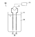
- Embodiment 1 In Embodiment 1, an example of the method and apparatus of the present invention will be described. The apparatus of Embodiment 1 is shown in FIG.
- the 1 includes a tank 11, a power source 12, a controller 13, and an electrode pair 20.
- the electrode pair 20 is disposed in the tank 11. That is, the tank 11 is an electrolytic tank.
- the electrode pair 20 includes a first electrode 21 and a second electrode 22.
- the power source 12 is connected to the first electrode 21 and the second electrode 22.
- the storage device of the controller 13 stores a program for executing each process.
- the controller 13 controls the voltage output from the power supply 12 according to the program.
- the tank 11 stores an aqueous solution 30 which is an aqueous solution (S).
- FIG. 2A A front view of an example of the first electrode 21 is shown in FIG. 2A.
- the electrode 21 in FIG. 2A includes a net-like electrode 21a and a lead 21b connected thereto.
- the second electrode 22 includes a net-like electrode and a lead.
- an expanded metal coated with platinum can be used for the net-like electrode.
- the first electrode 21 may include a plurality of net-like electrodes
- the second electrode 22 may include a plurality of net-like electrodes. By changing the number of net-like electrodes included in the electrodes, the ratio between the surface area of the first electrode 21 and the surface area of the second electrode 22 can be changed.
- FIG. 2B shows an example in which the first electrode 21 includes one net-like electrode 21a and the second electrode 22 includes nine net-like electrodes 22a. Spacers 23 are disposed between the net-like electrodes, and the net-like electrodes and the spacers 23 are laminated. Although the lead is not shown in FIG. 2B, the nine net-like electrodes 22a are connected by leads. In the example of FIG. 2B, the net-like electrodes 21a and the net-like electrodes 22a are not alternately arranged, but they may be alternately arranged.
- step (i) a DC voltage is applied between the first electrode 21 and the second electrode 22 so that the first electrode 21 serves as an anode and the second electrode 22 serves as a cathode.
- the voltage at this time is a voltage at which the concentration of free chlorine increases, for example, a voltage of 4 V or more (in the example, a voltage in the range of 5 V to 12 V) or a voltage of 7 V or more (in the example, a voltage in the range of 7 to 9 V) .
- an oxygen gas generation reaction due to water electrolysis and a chlorine molecule generation reaction due to oxidation of chlorine ions (2Cl ⁇ ⁇ Cl 2 + 2e ⁇ ) occur on the surface of the anode (first electrode 21).
- a chlorine molecule generation reaction due to oxidation of chlorine ions (2Cl ⁇ ⁇ Cl 2 + 2e ⁇ )
- Part of the generated chlorine molecules becomes hypochlorous acid and hypochlorite ions.
- a hydrogen gas generation reaction by water electrolysis and a free chlorine decomposition reaction occur on the surface of the cathode (second electrode 22).
- the decomposition reaction of free chlorine includes the following decomposition reaction of hypochlorous acid and reduction reaction of chlorine molecules. HClO + H + + 2e ⁇ ⁇ Cl ⁇ + H 2 O Cl 2 + 2e ⁇ ⁇ 2Cl ⁇
- aqueous solution 30 treated in the step (i) is used for sterilization (for example, sterilization washing) as necessary.
- step (ii) a DC voltage is applied between the electrode 21 and the electrode 22 so that one of them becomes an anode and the other becomes a cathode.
- the voltage may be applied so that the first electrode 21 becomes an anode and the second electrode 22 becomes a cathode.
- a voltage may be applied so that the first electrode 21 becomes a cathode and the second electrode 22 becomes an anode.
- the voltage at this time is a voltage at which the concentration of free chlorine decreases, for example, a voltage of 3 V or less (in the example, a voltage in the range of 0.9 V to 3.0 V) or a voltage of 1.8 V or less (in the example, 1.2 V to Voltage in the range of 1.8V).
- step (ii) free chlorine is generated at the anode and free chlorine disappears at the cathode, as in the voltage application in step (i).
- step (ii) by applying a lower voltage in step (ii) than in step (i), the extinction rate of free chlorine can be made higher than the generation rate of free chlorine.
- step (ii) the free chlorine concentration decreases with voltage application.
- the aqueous solution (S) having a reduced free chlorine concentration in step (ii) may be discarded, used for cleaning the sterilization target, or used for other purposes.
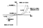
- FIG. 3 is a schematic graph expected from experimental results and may be different from the actual one.
- FIG. 3 is a schematic diagram and does not consider the ratio of voltage magnitudes.
- the horizontal axis indicates the potential of the electrode
- the vertical axis in FIG. 3 indicates the reaction current.
- the oxygen gas generation reaction is likely to occur at a lower potential than the chlorine ion oxidation reaction (free chlorine generation reaction). Therefore, by applying a low voltage, it is possible to cause an oxygen gas production reaction at the anode with almost no free chlorine production reaction. That is, in the step (ii), by adjusting the potential of the anode and the potential of the cathode (for example, by setting the direct-current voltage applied between the two to an appropriate value), the rate at which the free chlorine is generated at the cathode than at the anode. The disappearance rate of free chlorine can be increased. As a result, the free chlorine concentration can be reduced by step (ii).
- Patent Document 2 In conventional methods for reducing the free chlorine concentration by electrolysis, attention has been directed to increasing the decomposition reaction of free chlorine at the cathode.
- Patent Document 2 described above does not pay attention to the reaction at the anode, and describes that it is preferable to apply a voltage so that gas generation does not occur.
- the amount of free chlorine to be decomposed is very small as in the invention described in Patent Document 2, there is a possibility that the free chlorine concentration can be reduced even at a voltage at which no gas is generated.
- the amount of free chlorine to be decomposed is large, it is necessary to pass a sufficient current between the electrodes by causing a reaction accompanied by gas generation at the anode.
- the present inventors have found that in order to efficiently reduce free chlorine, it is necessary not only to focus on the decomposition of free chlorine at the cathode, but also to focus on the electrolysis at the anode.
- the anode in step (ii) is an electrode (platinum-coated electrode) having platinum on the surface. Since platinum has a large difference between an overvoltage for the oxygen gas generation reaction and an overvoltage for the oxidation reaction of chlorine ions, the oxidation reaction of chlorine ions can be suppressed by using a platinum-coated electrode.
- An aqueous solution (S) having a chlorine ion concentration of a predetermined value or less is used.
- the aqueous solution (S) having a low chlorine ion concentration By using the aqueous solution (S) having a low chlorine ion concentration, the oxidation reaction of chlorine ions can be suppressed.
- an aqueous solution having a chlorine ion concentration of 582 mmol / L or less may be used, for example, a chlorine ion concentration in the range of 17 mmol / L to 582 mmol / L (in one example, 86 mmol / L to 205 mmol / L).
- An aqueous solution in the range of L) may be used.
- the concentration thereof may be in the range of 0.1 wt% to 3.4 wt% (for example, in the range of 0.5 wt% to 1.2 wt%).
- (J3) Reduce the hydrogen ion concentration in the vicinity of the anode.
- the hydrogen ion concentration near the anode increases.
- the liquid becomes acidic and hypochlorous acid is easily generated. Therefore, in the step (ii), it is preferable to reduce the hydrogen ion concentration in the vicinity of the anode.
- the method for reducing the hydrogen ion concentration in the vicinity of the anode include the following methods. (J3-1) The flow rate of the aqueous solution (S) in the vicinity of the anode is increased to promote the diffusion of hydrogen ions in the vicinity of the anode.
- the average flow rate of the aqueous solution (S) flowing in the electrolytic cell may be 3.5 mm / second or more, or 6 mm / second or more.
- the upper limit of the average flow velocity is not particularly limited, but may be, for example, 30 mm / second or less.
- the anode is moved to stir the aqueous solution (S) near the anode to promote the diffusion of hydrogen ions near the anode.
- the aqueous solution (S) in the vicinity of the anode is stirred by rotating the anode.
- aqueous solution (S) in the vicinity of the anode is stirred by using a structure in which turbulent flow is generated in the vicinity of the anode, and the diffusion of hydrogen ions in the vicinity of the anode is promoted.
- a turbulent flow may be generated by providing irregularities on the surface of the anode.
- the oxidation reaction curve of chlorine ions can be moved as shown by a one-dot chain line A in FIG. Thereby, the free chlorine concentration can be efficiently reduced in the step (ii).
- the above conditions (J1) to (J3) are effective even if any one of them is implemented, but the effect is further enhanced by combining a plurality of conditions. Specifically, even if the condition is satisfied by a combination of (J1) and (J2), (J1) and (J3), (J2) and (J3), or (J1), (J2) and (J3) Good. In addition to these, the condition of (J4) described later may be satisfied.
- the generation rate of free chlorine at the anode can be made larger than the disappearance rate of free chlorine at the cathode.
- the free chlorine concentration can be increased by applying the voltage in step (i).
- steps (i) and (ii) are performed so that the following condition (J4) is satisfied.
- step (i) a DC voltage of 4 V or more (eg, in the range of 4 V to 12 V) is applied between the first anode and the first cathode, and in step (ii), the second anode and the first cathode A DC voltage in the range of 0.6 V to 3 V is applied between the two cathodes.
- a DC voltage of 5 V or more for example, in the range of 5V to 8V
- a DC voltage in the range of 0.9V to 3V for example, in the range of 1.2V to 3V
- the potential difference (applied voltage) between the electrodes may be changed as the processing proceeds.
- the DC voltage in the range of 1.8 to 3.0 V is applied between the electrodes at the beginning of step (ii) and the free chlorine concentration is reduced to 50 mg / L
- the DC voltage is 1.2 V or more and less than 1.8 V.
- a voltage may be applied.
- At least one condition selected from the group consisting of (J1), (J2), (J3) and (J4) may be satisfied.
- steps (i) and (ii) may be performed so as to satisfy all of (J1) to (J4).
- step (ii) can be replaced with step (ii ′).
- step (ii ′) a direct current is applied between two electrodes selected from a plurality of electrodes in a state where at least one condition selected from the group consisting of (J1), (J2), (J3) and (J4) is satisfied.
- step (J1), (J2), (J3) and (J4) is satisfied.
- the anode and the cathode in the step (i) and the anode and the cathode in the step (ii) are electrodes each having platinum on the surface, and satisfy the above condition (J4). Good.
- an aqueous solution (S) having a chlorine ion concentration in the range of 17 mmol / L to 582 mmol / L (in the range of 86 mmol / L to 205 mmol / L, for example) may be used.
- the average flow rate of the aqueous solution (S) flowing around the anode and the cathode may be 3.5 mm / second or more.
- the average flow rate of the aqueous solution (S) in the tank in which the anode and the cathode are disposed can be regarded as the average flow rate of the aqueous solution (S) flowing around the anode and the cathode.
- One method for increasing the average flow rate of the aqueous solution (S) flowing through the electrolytic cell is to reduce the cross-sectional area (C) of the electrode in the direction perpendicular to the direction in which the aqueous solution (S) flows.
- the amount of the aqueous solution (S) flowing through the electrolytic cell per unit time is the same, the smaller the cross-sectional area (C), the faster the average flow rate of the aqueous solution (S) flowing through the electrolytic cell.
- the electrolytic cell and the electrode disposed thereon are formed in a vertically long rectangular parallelepiped shape, and the aqueous solution (S) is allowed to flow along the longitudinal direction.
- the average flow rate of the aqueous solution (S) flowing through the electrolytic cell may be different between the step (i) and the step (ii). .
- the average flow rate in step (i) may be slower than the average flow rate in step (ii).
- the electric double layer on the electrode surface can be maintained, and the free chlorine concentration can be increased efficiently.
- the free chlorine concentration can be efficiently reduced in step (ii) as described above.
- the amount of the aqueous solution (S) flowing through the electrolytic cell per unit time is changed simply by adjusting a pump or a valve.
- This first method includes the configuration shown in FIG. 5 described later.
- a rectangular parallelepiped electrolytic cell (and a rectangular parallelepiped electrode group disposed therein) is used, and the direction in which the aqueous solution (S) flows is changed between step (i) and step (ii).
- the aqueous solution (S) is flowed in a direction perpendicular to the direction in which the cross-sectional area of the electrolytic cell is large in the step (i), and the aqueous solution (in the direction perpendicular to the direction in which the cross-sectional area of the electrolytic cell is small in the step (ii)) S).
- the electrolytic cell is changed between step (i) and step (ii). In this case, a plurality of electrolytic cells having different cross-sectional areas are used.
- Embodiment 2 In the second embodiment, an example of a method and apparatus for circulating an aqueous solution (S) between an electrolytic cell and the outside thereof will be described.
- the apparatus 200 of Embodiment 2 is shown in FIG.
- the apparatus 200 includes a tank 211, a power source 12, a controller 13, a pump 14, and an electrode pair 20.
- the electrode pair 20 is disposed in the tank 211. That is, the tank 211 is an electrolytic tank. Since the power supply 12, the controller 13, and the electrode pair 20 have been described in the first embodiment, redundant description will be omitted.
- FIG. 4 shows an example in which the electrode pair 20 shown in FIG. 2B is used.
- an inflow port 211a and an outflow port 211b are formed in the tank 211.
- a flow path 212 is connected to the inflow port 211a and the outflow port 211b so that a circulation path 301 including the sterilization target 300 is formed.
- the aqueous solution 30 as the aqueous solution (S) is circulated through the circulation path 301 by the pump 14 controlled by the controller 13.
- a flow path or tank for supplying the aqueous solution 30 and a flow path or tank for discharging the aqueous solution 30 after being used for sterilization are connected to the circulation path 301 as necessary.
- the position where the inflow port 211a and the outflow port 211b are formed is not particularly limited, and the inflow port 211a may be formed below the tank 211 and the outflow port 211b may be formed above the tank 211 as shown in FIG. . According to this arrangement, the gas generated on the electrode surface can be quickly separated from the electrode surface. As a result, it can suppress that the rate of an electrolysis reaction falls with the gas on the electrode surface.
- the net electrode may be arranged so that the in-plane direction of the net electrode is orthogonal to the flow of the aqueous solution 30.
- the step (ii) may be performed by arranging the first electrode 21 having a small surface area on the inflow port 211a side and applying a voltage so that the first electrode 21 becomes an anode. According to these configurations, the free chlorine concentration can be efficiently reduced.
- the process (I) (the sterilization process including the process (i)) is performed in a state where the aqueous solution 30 is circulated between the tank 211 and the sterilization target 300. Further, in the apparatus 200, the step (II) (the cleaning step including the step (ii)) may be performed in a state where the aqueous solution 30 is circulated between the tank 211 and the sterilization target 300. Steps (i) and (ii) can be performed in the same manner as in the first embodiment.
- An example of the sterilization target 300 is piping.
- the apparatus 200 sterilization cleaning in the piping is possible.
- the pipe include a blood processing apparatus pipe.
- the piping through which the dialysate passes needs to be sterilized before use.
- the inside of the pipe can be sterilized and washed by the step (I), and the free chlorine concentration in the pipe can be reduced by the step (II). Therefore, the present invention can be preferably used for sterilization of piping in the blood processing apparatus.
- the voltage application time in steps (i) and (ii) may be set according to the purpose. In addition, you may arrange
- the controller may control the voltage magnitude and the voltage application time based on the output of the sensor. Further, the controller may apply a voltage according to a predetermined condition.
- the tank 211 comprise a part of two circulation paths.
- a circulation path 302 is formed in parallel with the circulation path 301.
- the flow rate of the aqueous solution (S) in the circulation path 302 is controlled by a pump 303 provided in the circulation path 302.
- the flow rate (average flow rate) of the aqueous solution (S) in the tank 211 can be increased independently of the flow rate of the aqueous solution (S) in the circulation path 301. It is.
- the free chlorine concentration was measured by the DPD method (diethyl paraphenylenediamine method). Specifically, it was measured by a method for measuring free chlorine using HACH's absorptiometer (DR3900) (method 8021 disclosed by HACH). In this method, a sample and a reagent for measuring free chlorine concentration are put into a sample cell, and the free chlorine concentration is calculated by measuring the absorbance of the sample colored with the reagent.
- DPD method diethyl paraphenylenediamine method
- DR3900 absorptiometer
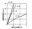
- Example 1 In Example 1, the relationship between the applied voltage and free chlorine concentration in step (i) was examined.
- Example 1 an electrode pair having the configuration shown in FIG. 2B was used.
- the net-like electrode constituting the anode and the cathode an electrode (length 35 mm, width 54 mm, thickness 1.8 mm) obtained by plating platinum on the surface of a titanium expanded metal was used.
- the first electrode 21 anode in this embodiment
- the second electrode 22 cathode in this embodiment
- the surface area of the cathode is about 9 times the surface area of the anode.
- a net-like resin spacer was disposed between the electrode plates.
- a sodium chloride aqueous solution (physiological saline) having a concentration of 0.9 wt% was prepared.
- Step (i) was performed on this aqueous solution.
- the electrode was placed in a beaker containing an aqueous solution, and a DC voltage was applied between the first electrode 21 (anode) and the second electrode 22 (cathode). The voltage was applied while stirring the aqueous solution with a stirrer.
- the aqueous solution in the beaker was circulated by a pump at a flow rate of 150 mL / min. The total amount of the aqueous solution was 1 L.
- four types of experiments were performed by changing the voltage application method. Specifically, the voltage was applied under the following four conditions.
- Example 1-1 Application of a constant voltage of 5V.
- Example 1-2 Application of a constant voltage of 7V.
- Example 1-3 Application of a constant voltage of 10V.
- Example 1-4 A voltage was applied so that a constant current of 2 A would flow between the electrodes (the applied voltage was about 8.5 V).
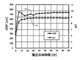
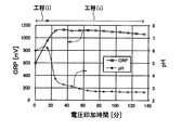
- FIG. 7 shows changes in the ORP (oxidation-reduction potential) and pH of the aqueous solution when a voltage of 5 V is applied. As shown in FIG. 7, when a voltage of 5 V was applied, the ORP and pH rose at the initial stage of voltage application, and were almost constant thereafter.
- Example 2 In Example 2, the relationship between the applied voltage and the free chlorine concentration in step (ii) was examined. In Example 2, the experiment was performed under the same conditions as in Example 1 except that the applied voltage was changed.
- Example 2 first, a voltage was applied for 15 minutes so that a constant current of 2 A flows between the first electrode 21 (anode) and the second electrode 22 (cathode) described in Example 1 (steps). (I)).
- the free chlorine concentration of the aqueous solution was about 200 mg / L (specifically, a range of 181 to 251 mg / L).
- step (ii) was performed.
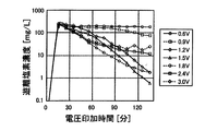
- seven types of experiments were performed by changing the applied voltage. Specifically, 0.6V (experiment 2-1), 0.9V (experiment 2-2), 1.2V between the first electrode 21 (anode) and the second electrode 22 (cathode). Constant voltage of (Experiment 2-3), 1.5V (Experiment 2-4), 1.8V (Experiment 2-5), 2.4V (Experiment 2-6), and 3.0V (Experiment 2-7) An experiment was conducted to apply. Then, the relationship between the free chlorine concentration in the aqueous solution and the voltage application time was examined. The measurement results are shown in FIG. 8A. Moreover, the graph which made the vertical axis
- FIG. 8A logarithmic display is shown to FIG. 8B.
- the voltage application time of 0 to 15 minutes in FIGS. 8A and 8B corresponds to the step (i), and the subsequent time corresponds to the step (ii).
- the voltages shown in the precedents of FIGS. 8A and 8B are the voltages applied in step (ii).
- the concentration of free chlorine was reduced by performing step (ii).
- the free chlorine concentration is greatly reduced when the applied voltage is in the range of 0.9 to 3.0V, and more when the applied voltage is in the range of 1.2V to 3.0V (particularly in the range of 1.2V to 1.8V). It decreased greatly. If the salt concentration in the aqueous solution is high, the rate of decrease in the free chlorine concentration can be increased by setting the applied voltage in the range of 1.8 V to 3.0 V.
- the decrease rate of the free chlorine concentration was large when the applied voltage was in the range of 2.4V to 3.0V.
- the free chlorine concentration was lower when the applied voltage was in the range of 1.2 to 1.8V.
- a voltage in the range of a relatively high voltage for example, 2.4 V to 3.0 V
- a lower voltage for example, 1.2 V to 1.8 V
- step (i) and step (ii) Although the same electrode is used in step (i) and step (ii), the free chlorine concentration is increased and decreased by changing the magnitude of the applied voltage. I was able to. It has not been known at all that the chlorine concentration can be controlled by such a method. The present invention is based on the fact that the above-described control is found for the first time by the inventors' research.
- Example 3 In Example 3, the experiment was performed by changing the ratio between the surface area of the anode and the surface area of the cathode.
- the cathode As the cathode, the second electrode 22 described in Example 1, that is, an electrode including nine net-like electrodes 22a was used.
- the net electrode 21a described in Example 1 was used as the net electrode constituting the anode, and the number of net electrodes constituting the anode was varied between 1 and 9.
- Table 1 shows the configuration of the electrodes used in Example 3. As shown in Table 1, the value of (cathode surface area) / (anode surface area) was varied in the range of 1.0 (experiment 3-5) to 9.0 (experiment 3-1).
- the experiment was carried out by a batch system as shown in FIG.
- Example 3 the experiment was performed under the same conditions as the experiment (2-3) of Example 2 except that the configuration of the electrode pair was changed. Specifically, first, a voltage was applied for 15 minutes so that a constant current of 2 A flows between the anode (first electrode 21) and the cathode (second electrode 22) (step (i)). By applying the voltage in step (i), the free chlorine concentration was about 200 mg / L (specifically, a range of 194 to 251 mg / L).
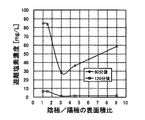
- step (ii) was performed for each of Experiments 3-1 to 3-5. Specifically, a constant voltage of 1.2 V was applied between the anode (first electrode 21) and the cathode (second electrode 22). And the change of the free chlorine concentration in the aqueous solution by process (ii) was measured. The measurement results are shown in FIG. As shown in FIG. 10, when 60 minutes have elapsed from the start of voltage application in step (ii), the free chlorine concentration is greatly reduced when the surface area ratio of the cathode / anode is in the range of 3.0 to 9.0. did.
- results in FIG. 10 suggest that the rate of decrease in free chlorine concentration can be increased by setting the cathode / anode surface area ratio in the range of 3.0 to 9.0.
- results of FIG. 10 show that the free chlorine concentration can be sufficiently reduced even when the cathode / anode surface area ratio is increased (ie, the amount of anode used is reduced) when the voltage is applied for a long time. It suggests.
- Example 4 the relationship between the concentration of alkali metal chloride in the aqueous solution and the change in free chlorine concentration was examined. Specifically, steps (i) and (ii) were performed by changing the concentration of sodium chloride in the aqueous solution. An electrode pair having the same configuration as in Example 1 was used as the electrode pair.
- a plurality of aqueous solutions with different concentrations of sodium chloride were prepared. Specifically, a plurality of sodium chloride aqueous solutions having a concentration in the range of 0.7 wt% to 10.8 wt% were prepared. Step (i) was performed on this sodium chloride aqueous solution. Specifically, the electrode pair is placed in a beaker containing 200 mL of an aqueous solution, and a voltage is set so that a constant current of 2 A flows between the first electrode 21 (anode) and the second electrode 22 (cathode). Was applied for 3 minutes. The voltage was applied while stirring the aqueous solution with a stirrer. By this voltage application, the free chlorine concentration in the aqueous solution became around 200 mg / L.
- step (ii) was performed.
- step (ii) a constant voltage of 1.2 V was applied between the first electrode 21 (anode) and the second electrode 22 (cathode). And the change of the free chlorine concentration by process (ii) was measured.
- the free chlorine concentration after performing the step (ii) is shown in FIG.
- the sodium chloride concentration and the voltage application time in step (ii) are as shown in Table 2.
- Example 5 In Example 5, the same experiment as in Example 4 was performed by changing the anode. In Example 5, the concentration of the sodium chloride aqueous solution is in the range of 0.9 wt% to 3.6 wt% (specifically, 0.9 wt%, 1.35 wt%, 1.8 wt%, and 3.6 wt%). The voltage was applied for 60 minutes in step (ii). Except for these, the experiment was performed under the same conditions as in Example 4.
- Example 5 an electrode having iridium oxide on the surface was used as the first electrode 21 (anode). Specifically, an electrode (JP-330) manufactured by Permerek Electrode Co., Ltd. was used. Of the electrode pair, the part other than the anode has the same configuration as the electrode pair of Example 1.
- Example 5 The result of Example 5 is shown in FIG. In FIG. 12, the results of Example 4 are also shown for comparison. As shown in FIG. 12, in Example 5 using the anode in which iridium oxide was present on the surface, the free chlorine concentration could be greatly reduced when the sodium chloride concentration was lower than about 1.5 wt%. On the other hand, in Example 4 using an anode having platinum on the surface, the free chlorine concentration could be greatly reduced when the sodium chloride concentration was lower than about 3.4%. These results suggest that the concentration of free chlorine in an aqueous solution having a wide range of salt concentrations can be efficiently reduced by using an electrode having platinum on the surface as an anode.
- Example 6 In Example 6, an experiment was conducted to increase and decrease the free chlorine concentration using a liquid-type electrolytic cell similar to the electrolytic cell 211 shown in FIG. As the electrode pair, the same electrode pair as that used in Example 1 was used.
- a sodium chloride aqueous solution (physiological saline) having a concentration of 0.9 wt% was used. 200 mL of this aqueous solution was circulated in a circulation channel including an electrolytic cell. And the process (i) and (ii) were performed in the state.
- step (i) a voltage was applied for 4 minutes so that a constant current of 2 A would flow between the first electrode 21 (anode) and the second electrode 22 (cathode). By this voltage application, the free chlorine concentration in the aqueous solution became around 200 mg / L.
- a voltage of 1.2 V was applied for 60 minutes between the first electrode 21 (anode) and the second electrode 22 (cathode).
- step (i) and (ii) were performed with the average flow rate of the aqueous solution in the electrolytic cell being 150 mL / min, 400 mL / min, and 800 mL / min. These flow rates correspond to 1.3 mm / second, 3.5 mm / second, and 7.1 mm / second, respectively, in terms of the average flow velocity in the electrolytic cell.
- FIG. 13 shows the free chlorine concentration after voltage application in step (ii). As shown in FIG. 13, the free chlorine concentration tended to decrease greatly as the flow rate increased. Specifically, the free chlorine concentration was greatly reduced when the flow rate was 3.5 mm / second or more.
- Example 7 In Example 7, an example in which the surface area of the second cathode is made larger than the surface area of the first cathode will be described.
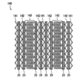
- the configuration of the electrode unit 140 used in Example 7 is schematically shown in FIG.
- the electrolytic cell used in Example 7 is schematically shown in FIG.
- the 14 includes a first electrode 141, a second electrode 142, a third electrode 143, and a spacer 23.
- the first to third electrodes 141 to 143 are made of the same net electrode. However, the number of net-like electrodes included in these electrodes is different.
- the first electrode 141 was composed of three net-like electrodes.
- the second electrode 142 was composed of four net-like electrodes.
- the third electrode 143 was composed of 22 net-like electrodes. 14 and 15, the number of net-like electrodes constituting the third electrode 143 is reduced for easy illustration.
- a platinum-coated electrode having a size of 80 mm ⁇ 60 mm and a thickness of 0.5 mm was used.
- As the spacer 23 a resin net-like spacer having a size of 80 mm ⁇ 60 mm and a thickness of 0.5 mm was used.
- the electrode unit 140 was placed in the tank 211 so that each net electrode was parallel to the direction in which the aqueous solution flows. And the circulation path containing the inflow port 211a and the outflow port 211b was formed, and 1.5L of salt solution was arrange
- a saline solution having a free chlorine concentration of about 240 to 250 ppm ( ⁇ 240 to 250 mg / L) and a NaCl concentration of 0.65 wt% was used as the salt solution.
- the flow rate of the saline solution flowing through the circulation path was 0.3 L / min. And the process (ii) was performed in the state which circulated the salt solution.
- Example 7 the step (ii) was performed by changing the ratio between the surface area of the second anode and the surface area of the second cathode.
- Table 3 shows the electrode area ratio in each experiment.
- the first electrode 141 of the electrode unit 140 was used as the second anode, and the second electrode 142 and the third electrode 143 were used as the second cathode.
- (surface area of the second cathode) / (surface area of the second anode) 26/3. That is, the surface area of the second cathode is about 9 times the surface area of the second anode.
- the first electrode 141 was the second anode
- the second electrode 142 was the second cathode
- no voltage was applied to the third electrode 143.
- Experiment 7-2 an experiment was performed in the same manner as Experiment 7-1 except that the number of net-like electrodes constituting the third electrode 143 of the electrode unit 140 was 12. In Experiment 7-2, the number of net-like electrodes constituting the third electrode 143 was reduced, so that the electrode unit became thinner and a space was created in the tank 211. In Experiment 7-2, a spacer 23 was placed in the space to prevent the saline flow from concentrating in the space.
- FIG. 16 shows the change in free chlorine concentration in Experiments 7-1 to 7-3.
- the step (i) may be performed using an electrode unit including the third electrode 143 without applying a voltage to the third electrode 143.
- step (i) may be performed using the first electrode 141 as a first anode and the second electrode 142 as a first cathode.
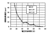
- Example 8 In Example 8, steps (i) and (ii) were performed to measure the change in free chlorine concentration. In step (ii) of Example 8, the voltage applied between the electrodes was reduced stepwise. In Example 8, the same electrode unit and circuit as in Experiment 7-1 of Example 7 were used. A salt solution having a NaCl concentration of 0.65 wt% was placed in this circulation path and circulated, and steps (i) and (ii) were performed in this state.
- step (i) a DC voltage of 6 V was applied between the first anode and the first cathode.
- step (ii) the magnitude of the DC voltage applied between the second anode and the second cathode was initially 2V, then 1.5V, and then 1.2V.
- the change in free chlorine concentration is shown in FIG. 17A.
- a partially enlarged view of FIG. 17A is shown in FIG. 17B.
- step (i) in which a DC voltage of 6 V is applied between the electrodes, the free chlorine concentration increases as shown in FIG. 17A.
- step (ii) of applying a DC voltage of 2 V between the electrodes the free chlorine concentration decreases as shown in FIG. 17A.
- the free chlorine concentration decreases again.
- the free chlorine concentration does not decrease to 4-5 ppm or less as shown in FIG. 17B.
- the applied voltage is changed to 1.2 V, the free chlorine concentration decreases again.
- the free chlorine concentration could be 1 ppm or less.
- the free chlorine concentration could be reduced extremely in a short time by decreasing the applied voltage stepwise in step (ii).
- the present invention can be used for a method and apparatus for controlling the free chlorine concentration, and a sterilization method and sterilization apparatus using them.
Landscapes
- Chemical & Material Sciences (AREA)
- Engineering & Computer Science (AREA)
- Chemical Kinetics & Catalysis (AREA)
- Health & Medical Sciences (AREA)
- Electrochemistry (AREA)
- Organic Chemistry (AREA)
- Life Sciences & Earth Sciences (AREA)
- Materials Engineering (AREA)
- Metallurgy (AREA)
- General Chemical & Material Sciences (AREA)
- Veterinary Medicine (AREA)
- Public Health (AREA)
- General Health & Medical Sciences (AREA)
- Animal Behavior & Ethology (AREA)
- Epidemiology (AREA)
- Hydrology & Water Resources (AREA)
- Water Supply & Treatment (AREA)
- Environmental & Geological Engineering (AREA)
- Inorganic Chemistry (AREA)
- Automation & Control Theory (AREA)
- Water Treatment By Electricity Or Magnetism (AREA)
- Electrolytic Production Of Non-Metals, Compounds, Apparatuses Therefor (AREA)
- Apparatus For Disinfection Or Sterilisation (AREA)
- Electrodes For Compound Or Non-Metal Manufacture (AREA)
Abstract
遊離塩素濃度を簡単に制御できる新規な方法およびそれを用いた殺菌方法、ならびに遊離塩素濃度を簡単に制御できる新規な装置を提供する。開示される方法は、複数の電極を用いて遊離塩素濃度を制御する。この方法は、工程(i)および工程(ii)をこの順に含む。工程(i)では、塩素イオンを含む水溶液30中において、第1の陽極の電位と第1の陰極の電位とを調整することによって、水溶液30中の遊離塩素濃度を上昇させる。工程(ii)では、水溶液30中において、第2の陽極の電位と第2の陰極の電位とを調整することによって、水溶液30中の遊離塩素濃度を低下させる。工程(ii)における第2の陽極の電位と第2の陰極の電位との差は、工程(i)における第1の陽極の電位と第1の陰極の電位との差よりも小さい。
Description
本発明は、遊離塩素濃度を制御する方法および装置、ならびにそれらを用いた殺菌方法および殺菌装置に関する。
塩水から次亜塩素酸塩を生成させて殺菌を行う方法が従来から提案されている。たとえば、陽イオン交換膜を用いた電気分解によって次亜塩素酸塩を生成させる方法が提案されている(特許文献1)。
次亜塩素酸塩を用いて殺菌を行う場合、殺菌後に残存する次亜塩素酸塩を除去することが好ましい場合がある。そのため、次亜塩素酸塩を除去する方法が従来から提案されている。たとえば、有効塩素成分を含有する被処理水を単極式電解槽に供給し、陰極で有効塩素成分を分解または還元する方法が提案されている(特許文献2)。特許文献2には、陰極材料として炭素系材料を用いること、および、実質的なガス発生を伴わない低い電圧を印加することが好ましい旨が記載されている。
また、次亜塩素酸塩の生成と分解とを電圧の印加によって行う方法も提案されている(特許文献3)。特許文献3には、一対の交流電極と、所定の2つの接地電極とを用いることによって、次亜塩素酸ナトリウムの発生と還元とが可能であることが記載されている。
特許文献1の方法では陽イオン交換膜を使用する必要があるため、陽イオン交換膜の再生が必要となり、装置の管理が複雑であるとともに維持コストが高くなる。また、特許文献2には、遊離塩素濃度を低下させる方法しか開示されていない。また、特許文献3の方法で実際にどの程度の効果があるのかについては特許文献3に示されておらず、特許文献3の方法の有効性は不明である。
このような状況において、本発明の目的の1つは、遊離塩素濃度を簡単に制御できる新規な方法およびそれを用いた殺菌方法、ならびに遊離塩素濃度を簡単に制御できる新規な装置を提供することである。
上記目的を達成するために検討した結果、本願発明者らは従来知られていなかった現象を見いだした。本発明は、この新たな知見に基づくものである。
本発明は、遊離塩素濃度を制御する1つの方法を提供する。この方法は、複数の電極を用いて遊離塩素濃度を制御する方法であって、(i)塩素イオンを含む水溶液中において、第1の陽極の電位と第1の陰極の電位とを調整することによって、前記水溶液中の遊離塩素濃度を上昇させる工程と、(ii)前記水溶液中において、第2の陽極の電位と第2の陰極の電位とを調整することによって、前記水溶液中の遊離塩素濃度を低下させる工程と、をこの順に含み、前記(ii)の工程における前記第2の陽極の電位と前記第2の陰極の電位との差が、前記(i)の工程における前記第1の陽極の電位と前記第1の陰極の電位との差よりも小さく、前記第1の陽極および前記第1の陰極はそれぞれ、前記複数の電極の一部および他の一部によって構成され、前記第2の陽極および前記第2の陰極はそれぞれ、前記複数の電極の一部および他の一部によって構成される。
さらに、本発明は、1つの殺菌方法を提供する。この殺菌方法は、遊離塩素を含む水溶液を用いて殺菌を行う殺菌方法であって、遊離塩素濃度を制御するための本発明の方法を含み、(I)上記(i)の工程で処理された前記水溶液を用いて殺菌対象を殺菌する工程を含む。
さらに、本発明は、1つの装置を提供する。この装置は、遊離塩素濃度を制御する装置であって、複数の電極と、前記複数の電極に電圧を印加するための電源と、前記電源を制御するためのコントローラとを備え、前記コントローラは、上記工程(i)および(ii)をこの順に実行し、前記(ii)の工程における前記第2の陽極の電位と前記第2の陰極の電位との差が、前記(i)の工程における前記第1の陽極の電位と前記第1の陰極の電位との差よりも小さく、前記第1の陽極および前記第1の陰極はそれぞれ、前記複数の電極の一部および他の一部によって構成され、前記第2の陽極および前記第2の陰極はそれぞれ、前記複数の電極の一部および他の一部によって構成される。
さらに、本発明は、1つの殺菌装置を提供する。この殺菌装置は、遊離塩素を含む水溶液を用いて殺菌を行う殺菌装置であって、遊離塩素濃度を制御するための本発明の装置を含み、前記コントローラは、(I)前記(i)の工程で処理された前記水溶液を用いて殺菌対象を殺菌する工程を実行する。
本発明の方法および装置によれば、水溶液中の遊離塩素濃度を簡単に制御できる。また、本発明の殺菌方法および殺菌装置では、遊離塩素濃度が上昇した水溶液を用いて殺菌対象を殺菌できる。
本発明の実施形態について以下に説明する。なお、以下の説明では本発明の実施形態について例を挙げて説明するが、本発明は以下に説明する例に限定されない。以下の説明では、具体的な数値や材料を例示する場合があるが、本発明の効果が得られる限り、他の数値や材料を適用してもよい。図面を用いた説明では、同様の部分に同一の符号を付して重複する説明を省略する場合がある。
(遊離塩素濃度の制御方法)
遊離塩素濃度(有効塩素濃度)を制御するための本発明の方法の一例について以下に説明する。この方法では、複数の電極を用いて遊離塩素濃度を制御する。この方法は、以下で説明する工程(i)および工程(ii)をこの順に含む。典型的には、複数の電極は、1組の電極対を構成する2つの電極からなる。ただし、本発明では、それら2つの電極以外の他の電極をさらに含んでもよい。
遊離塩素濃度(有効塩素濃度)を制御するための本発明の方法の一例について以下に説明する。この方法では、複数の電極を用いて遊離塩素濃度を制御する。この方法は、以下で説明する工程(i)および工程(ii)をこの順に含む。典型的には、複数の電極は、1組の電極対を構成する2つの電極からなる。ただし、本発明では、それら2つの電極以外の他の電極をさらに含んでもよい。
工程(i)では、塩素イオンを含む水溶液中において、複数の電極から選ばれる2つの電極が陽極および陰極として機能するように当該2つの電極の電位を調整することによって、水溶液中の遊離塩素濃度を上昇させる。以下では、工程(i)および(ii)で処理される水溶液を、「水溶液(S)」という場合がある。また、工程(i)における陽極および陰極をそれぞれ、「第1の陽極」および「第1の陰極」という場合がある。
別の観点では、工程(i)では、塩素イオンを含む水溶液(S)中において、第1の陽極の電位と第1の陰極の電位とを調整することによって、水溶液(S)中の遊離塩素濃度を上昇させる。第1の陽極および第1の陰極はそれぞれ、複数の電極の一部および他の一部によって構成される。複数の電極は、第1の陽極および第1の陰極を構成しない電極を含んでもよい。
2つの電極の電位を調整する例には、2つの電極間の電位差を調整することが含まれ、たとえば、2つの電極間に直流電圧を印加することによって2つの電極間の電位差を調整することが含まれる(工程(ii)においても同様である)。すなわち、工程(i)の一例では、第1の陽極と第1の陰極との間に直流電圧を印加し、その電圧印加のみによってそれらの電極の電位を調整する。
工程(i)では、陽極の表面で塩素イオンが酸化されて塩素分子が生じる。この塩素分子は水と反応して次亜塩素酸や次亜塩素酸イオンを生じる。すなわち、工程(i)の電圧印加によって、遊離塩素(溶存塩素、次亜塩素酸、および次亜塩素酸イオン)の濃度が上昇する。
水溶液(S)は塩素イオンを含む。水溶液(S)の好ましい一例は、アルカリ金属塩化物などの金属塩化物が溶解している水である。アルカリ金属塩化物の例には、塩化ナトリウム(NaCl)および塩化カリウム(KCl)が含まれる。水溶液(S)の一例は、塩化ナトリウムおよび塩化カリウムから選ばれる少なくとも1種が溶解している水溶液であり、塩化ナトリウム水溶液であってもよい。また、水溶液(S)の例には、生理食塩水(塩化ナトリウム水溶液)や、血液処理装置で用いられる液体(たとえば人工透析装置で用いられる透析液)が含まれる。透析液の主要な成分は塩化ナトリウムであり、その濃度は約0.7wt%である。水溶液(S)の例には、水道水や地下水も含まれる。
塩素イオン濃度が低すぎると、工程(i)において、遊離塩素濃度を充分に高めることができなかったり、水溶液(S)における電圧降下が大きくなったりする場合がある。一方、塩素イオン濃度が高すぎると、後述する工程(ii)において遊離塩素濃度を低減するために必要な時間が長くなる場合がある。そのため、水溶液(S)中の塩素イオン濃度は適切な範囲にあることが好ましい。水溶液(S)の塩素イオン濃度は、17ミリモル/L~582ミリモル/Lの範囲にあってもよい。なお、塩素イオン濃度が17ミリモル/Lとなる塩化ナトリウム水溶液(塩化ナトリウムのモル質量:58.4g/モル)の濃度は、約0.1wt%(0.017×58.4×100/1000)である。塩素イオン濃度が582ミリモル/Lとなる塩化ナトリウム水溶液の濃度は、約3.4wt%(0.582×58.4×100/1000)である。水溶液(S)がアルカリ金属塩化物(たとえば塩化ナトリウムおよび/または塩化カリウム)の水溶液である場合には、濃度が0.7wt%~7.2wt%の範囲にあってもよい。
工程(ii)では、水溶液(S)中において、複数の電極から選ばれる2つの電極が陽極および陰極として機能するように2つの電極の電位を調整することによって、水溶液(S)中の遊離塩素濃度を低下させる。以下では、工程(ii)の電圧印加における陽極および陰極をそれぞれ、「第2の陽極」および「第2の陰極」という場合がある。
別の観点では、工程(ii)では、水溶液(S)中において、第2の陽極の電位と第2の陰極の電位とを調整することによって、水溶液(S)中の遊離塩素濃度を低下させる。第2の陽極および第2の陰極はそれぞれ、複数の電極の一部および他の一部によって構成される。複数の電極は、第2の陽極および第2の陰極を構成しない電極を含んでもよい。
本発明の方法では、工程(ii)における2つの電極の電位差(第2の陽極の電位と第2の陰極の電位との差)を、工程(i)における2つの電極の電位差(第1の陽極の電位と第1の陰極の電位との差)よりも小さくする。
工程(ii)では、遊離塩素成分が第2の陰極の表面で分解され、その結果、水溶液(S)中の遊離塩素濃度が減少する。そのため、第2の陰極の表面積を大きくすることによって、遊離塩素を効率的に減少させることが可能である。たとえば、工程(ii)における第2の陰極の表面積は、工程(ii)における第2の陽極の表面積よりも大きくてもよい。第2の陰極の表面積を第2の陽極の表面積よりも大きくすることによって、電極全体のサイズを小さくするとともに遊離塩素濃度の減少速度を大きくすることができる。
第2の陰極の表面積は第2の陽極の表面積よりも大きくてもよい。一例では、第2の陰極の表面積が第1の陰極の表面積よりも大きく、且つ、第2の陰極の表面積が第2の陽極の表面積よりも大きい。すなわち、第2の陰極の表面積は、第1の陰極の表面積および第2の陽極の表面積のいずれよりも大きくてもよい。第2の陰極の表面積は、第2の陽極の表面積の2倍以上や3倍以上であってもよく、20倍以下や12倍以下や9倍以下であってもよい。たとえば、第2の陰極の表面積は、第2の陽極の表面積の2~12倍の範囲や3~12倍の範囲や3~9倍の範囲にあってもよい。
一例では、以下の(1)および(2)の条件が満たされ、さらに(3)の条件が満たされてもよい。
(1)第1の陰極の表面積が第1の陽極の表面積の0.5~2倍の範囲にある。
(2)第2の陰極の表面積が第2の陽極の表面積の2~12倍の範囲や3~12倍の範囲や3~9倍の範囲にある。
(3)第1の陽極の表面積が、第2の陽極の表面積の0.5~2倍の範囲にある。
(1)第1の陰極の表面積が第1の陽極の表面積の0.5~2倍の範囲にある。
(2)第2の陰極の表面積が第2の陽極の表面積の2~12倍の範囲や3~12倍の範囲や3~9倍の範囲にある。
(3)第1の陽極の表面積が、第2の陽極の表面積の0.5~2倍の範囲にある。
一例では、複数の電極は、第1の陽極として用いられる第1の電極と、第1の陰極として用いられる第2の電極と、第3の電極とを含んでもよい。この一例では、工程(i)において第3の電極に電圧が印加されなくともよく、工程(ii)において第2の陰極の少なくとも一部として第3の電極が用いられてもよい。たとえば、工程(ii)において、第1の電極を第2の陽極として用い、第2および第3の電極を第2の陰極として用いてもよい。好ましい一例では、第3の電極の表面積を第1の電極の表面積の2~11倍の範囲とし、第3の電極の表面積を第2の電極の表面積の2~11倍の範囲とする。第3の電極を用いた一例については、実施例7で説明する。
工程(i)では、遊離塩素濃度が上昇するように電極の電位を調整する。一方、工程(ii)では、遊離塩素濃度が低下するように電極の電位を調整する。遊離塩素濃度が上昇する電位およびそれが低下する電位は、それぞれ、水溶液(S)の溶質および濃度、ならびに電極の材質によって変化する場合がある。そのため、それらを考慮して電位を調整することが好ましい。
陽極と陰極との間に印加する直流電圧の大きさを制御することによって電位を調整する場合、工程(i)では遊離塩素濃度が上昇するように直流電圧を印加し、工程(ii)では、遊離塩素濃度が低下するように直流電圧を印加する。この場合、工程(ii)において電極間に印加される直流電圧の大きさを、工程(i)において電極間に印加される直流電圧の大きさよりも小さくする。
工程(i)および(ii)で用いられる陽極および陰極の形状に特に限定はない。それらは、板状の電極であってもよいし、それ以外でもよい。電極表面における反応を促進させる観点から、表面積が大きい電極を用いたり、水溶液(S)が通過する流路が形成されている電極を用いたりしてもよい。たとえば、金属製のワイヤを組み合わせて形成された電極(ネット状電極など)や、多孔質電極を用いてもよい。また、貫通孔が形成された電極、たとえば、パンチングメタルやエキスパンドメタルを用いた電極を用いてもよい。
陽極および陰極はそれぞれ、2次元方向に広がる形状を有する電極であってもよい。たとえば、陽極および陰極はそれぞれ、貫通孔が形成された平板状の電極であってもよいし、ネット状の電極であってもよい。それらの平らな電極は、図4に示すように、それらの面内方向が水溶液(S)の流れの方向に対して直交するように配置されてもよい。あるいは、それらの平らな電極は、図15に示すように、それらの面内方向が水溶液(S)の流れの方向と平行になるように配置されてもよい。
本発明において、複数の電極は、2つの電極からなるものであってもよい。なお、この明細書において、配線等で接続されて実質的に同電位にある複数の電極が1つの陽極または1つの陰極として機能する場合には、それら複数の電極を1つの電極として数える。
工程(i)において電位が調整される2つの電極(第1の陽極および第1の陰極)を、工程(ii)において電位が調整される2つの電極(第2の陽極および第2の陰極)として用いてもよい。たとえば、工程(i)における陽極および陰極を、それぞれ、工程(ii)における陽極および陰極として用いてもよい。すなわち、工程(i)と工程(ii)とで、陽極および陰極を変更することなく(電圧の印加方向を変更することなく)、電圧を印加してもよい。また、工程(i)における陽極および陰極を、それぞれ、工程(ii)における陰極および陽極として用いてもよい。すなわち、工程(ii)では、工程(i)と逆方向に電圧を印加してもよい。また、工程(ii)の陽極および陰極の少なくとも一方を、工程(i)の陽極および陰極とは異なる電極としてもよい。
本発明の一例では、工程(i)において電位が調整される2つの電極間(第1の陽極と第1の陰極との間)に直流電圧を印加することによって当該2つの電極の電位を調整し、工程(ii)において電位が調整される2つの電極間(第2の陽極と第2の陰極との間)に直流電圧を印加することによって当該2つの電極の電位を調整する。
電極の好ましい一例は表面に白金が存在する電極である。以下では、表面に白金が存在する電極(たとえば、白金によって表面がコートされた電極)を、「白金コート電極」という場合がある。白金コート電極は、工程(ii)の陽極として好ましく用いられる。複数の電極のすべてが白金コート電極であってもよい。電極の他の例には、表面に酸化イリジウムが存在する電極(たとえば、酸化イリジウムによって表面がコートされた電極)が含まれる。以下では、表面に酸化イリジウムが存在する電極を、「酸化イリジウムコート電極」という場合がある。
遊離塩素濃度を低下させる工程(ii)では、白金コート電極を陽極に用いることが好ましい。また、遊離塩素濃度を上昇させる工程(i)では、酸化イリジウムコート電極を陽極に用いることが好ましい。本発明の一例では、複数の電極として、白金コート電極と酸化イリジウムコート電極とを用いてもよい。この一例では、工程(i)において酸化イリジウムコート電極を陽極とし白金コート電極を陰極として両者の間に直流電圧を印加し、工程(ii)において白金コート電極を陽極とし酸化イリジウムコート電極を陰極として両者の間に直流電圧を印加する。この構成によれば、工程(i)において効率的に遊離塩素濃度を上昇させることができ、工程(ii)において効率的に遊離塩素濃度を低下させることができる。
電極間には、スペーサを配置してもよい。スペーサを配置する目的の1つは、陽極と陰極とが短絡することを防止することである。また、スペーサを配置することによって、電極間を水溶液(S)が流れやすくすることができる。スペーサには、絶縁性のスペーサを用いることができ、たとえば樹脂製のスペーサを用いることができる。スペーサの好ましい一例は、ネット状の樹脂製スペーサである。
工程(i)および(ii)は、それぞれ独立に、バッチ方式で行われてもよいし通液方式で行われてもよい。バッチ方式では、陽極および陰極が配置された電解槽内の水溶液(S)は、各工程において実質的に移動されない。一方、通液方式では、各工程において、水溶液(S)は電解槽と電解槽の外部との間で移動する。典型的な通液方式では、水溶液(S)は連続的に電解槽を流れる。
工程(i)における第1の陽極の電位と第1の陰極の電位との差は、4V以上、5V以上、または7V以上であってもよく、60V以下、20V以下、または12V以下であってもよい。工程(ii)における第2の陽極の電位と第2の陰極の電位との差は、4V未満、3V以下、または2V以下であってもよく、0.6V以上や1.2V以上であってもよい。
一例では、工程(i)において第1の陽極と第1の陰極との間に4V以上(たとえば4V~12Vの範囲や5V~12Vの範囲)の直流電圧が印加され、工程(ii)において第2の陽極と第2の陰極との間に0.6V~3Vの範囲(たとえば1.2V~3Vの範囲)にある直流電圧が印加される。この一例では、第1の陽極、第1の陰極、第2の陽極、および第2の陰極はそれぞれ、表面に白金が存在する電極であってもよい。
本発明の一例では、工程(ii)において、第2の陽極の電位と第2の陰極の電位との差を徐々に小さくしてもよい。この構成によれば、遊離塩素濃度をより短時間で低下させたり、遊離塩素濃度を極めて低くしたりすることができる場合がある。電位差を徐々に小さくする場合、電位差を連続的に小さくしてもよいし、電位差を段階的に小さくしてもよい。たとえば、工程(ii)の初期において第2の陽極と第2の陰極との電位差を2V~3Vの範囲とし、その後、その電位差を1.2V以上2V未満としてもよい。電位差を徐々に小さくする場合、最終の電位差を0.6V以上1.2V未満としてもよい。たとえば、工程(ii)の初期において第2の陽極と第2の陰極との電位差を2V~3Vの範囲とし、工程(ii)の最終において、その電位差を0.6V以上1.2V未満としてもよい。
特許文献1の方法とは異なり、本発明の方法では、イオン交換膜などのイオン交換材料を用いることなく遊離塩素濃度を制御できる。そのため、本発明の方法を実施するための装置の維持が容易である。ただし、本発明において、必要に応じてイオン交換材料を用いてもよい。
(殺菌方法)
本発明の殺菌方法について、以下に一例を説明する。本発明の殺菌方法は、遊離塩素を含む水溶液を用いて殺菌を行う方法である。この殺菌方法は、遊離塩素濃度を制御するための本発明の方法を含む。すなわち、この殺菌方法は上述した工程(i)および(ii)をこの順に含む。遊離塩素濃度の制御方法について記載した事項は、本発明の殺菌方法に適用できるため、重複する説明を省略する場合がある。また、本発明の殺菌方法について説明した事項は、遊離塩素濃度の制御方法に適用できる。また、別の観点では、この明細書において殺菌を洗浄と読み替えることが可能である。たとえば、本発明の殺菌方法および殺菌装置は、洗浄方法および洗浄装置と読み替えることが可能である。
本発明の殺菌方法について、以下に一例を説明する。本発明の殺菌方法は、遊離塩素を含む水溶液を用いて殺菌を行う方法である。この殺菌方法は、遊離塩素濃度を制御するための本発明の方法を含む。すなわち、この殺菌方法は上述した工程(i)および(ii)をこの順に含む。遊離塩素濃度の制御方法について記載した事項は、本発明の殺菌方法に適用できるため、重複する説明を省略する場合がある。また、本発明の殺菌方法について説明した事項は、遊離塩素濃度の制御方法に適用できる。また、別の観点では、この明細書において殺菌を洗浄と読み替えることが可能である。たとえば、本発明の殺菌方法および殺菌装置は、洗浄方法および洗浄装置と読み替えることが可能である。
本発明の殺菌方法は、工程(I)を含む。工程(I)では、工程(i)で処理された水溶液(S)を用いて殺菌対象を殺菌する。工程(i)で処理された水溶液(S)は遊離塩素濃度が高くなっているため、工程(I)によって殺菌を行うことができる。
本発明の殺菌方法は、工程(I)の後に、工程(ii)で処理された水溶液(S)を用いて殺菌対象を洗浄する工程(II)をさらに含んでもよい。工程(ii)で処理された水溶液(S)は遊離塩素濃度が低くなっている。そのため、工程(II)によれば、高濃度の遊離塩素が殺菌対象に残留することを防止できる。工程(II)を行わずに、洗浄用の水によって遊離塩素濃度を低減する場合には、洗浄に多量の水が必要となるが、工程(II)を行うことによって、そのような水の使用を削減することができる。
本発明の殺菌方法で殺菌される対象に特に限定はない。殺菌対象の例には、医療機器、医療器具、食器、その他の機器や物品が含まれる。医療機器の例には、血液処理装置(たとえば、人工透析装置などの血液浄化装置)が含まれる。特に、血液処理装置中の配管(たとえば、血液や透析液が通る配管)が好ましく殺菌される。本発明の殺菌方法は、医療分野に限らず、他の工業分野でも利用できる。
本発明の殺菌方法の一例では、工程(i)および(ii)における電圧の印加が電解槽内で行われ、電解槽と殺菌対象との間で水溶液(S)を循環させた状態で工程(i)および(ii)を行うことによって殺菌対象が殺菌される。すなわち、この一例では、電解槽と殺菌対象との間で循環している水溶液(S)によって殺菌が行われる。この構成によれば、少ない水溶液(S)で充分な殺菌を行うことが可能である。また、水溶液(S)を廃棄する場合の廃液の量を減らすことができる。この構成の一例では、殺菌対象が血液処理装置の配管である。
本発明の方法は、工程(i)と工程(ii)との間に、または、工程(ii)の後に、上記複数の電極から選ばれる2つの電極の電位を調整することによって、水溶液(S)中の遊離塩素濃度を一定の範囲に維持する工程をさらに含んでもよい。以下では、この工程を「工程(x)」という場合がある。
別の観点では、工程(x)は、水溶液(S)中において、第3の陽極の電位と第3の陰極の電位とを調整することによって、水溶液(S)中の遊離塩素濃度を一定の範囲に維持する工程である。第3の陽極および第3の陰極はそれぞれ、複数の電極の一部および他の一部によって構成される。
水溶液(S)を常に殺菌したり、水溶液(S)で殺菌される殺菌対象を常に殺菌したりする場合、水溶液(S)の遊離塩素濃度を一定の範囲に維持することが好ましい。そのような場合に、工程(x)が好ましく行われる。
実施例に示すように、陽極と陰極との間の電位差を所定の値以上とすると遊離塩素濃度が上昇し、当該電位差を所定の値以下とすると遊離塩素濃度が低下する。そのため、印加する電圧を制御することによって遊離塩素濃度を一定の範囲に維持することができる。たとえば、遊離塩素濃度が設定した範囲よりも低くなった場合には高い電圧(たとえば4V以上で、一例では4V~10Vの範囲)を印加し、遊離塩素濃度が設定した範囲よりも高くなった場合には低い電圧(たとえば3V以下で、一例では0.9V~3Vの範囲)を印加してもよい。また、所定の電圧(たとえば1.8V~4.0Vの範囲の電圧)の印加を続けることによって、遊離塩素濃度を一定の範囲に維持してもよい。
工程(i)の終了後、工程(ii)の終了後、および工程(x)中のそれぞれにおける水溶液(S)の遊離塩素濃度の目標値は、用途に応じて設定すればよい。工程(i)が終了した後の水溶液(S)の遊離塩素濃度は、10mg/L~500mg/Lの範囲(たとえば100mg/L~300mg/Lの範囲)の範囲にあってもよい。この範囲とすることによって、高い殺菌効果が得られる。また、工程(ii)が終了した後の水溶液(S)の遊離塩素濃度は、0.01mg/L~10mg/Lの範囲(たとえば0.01mg/L~1mg/Lの範囲)の範囲にあってもよい。この範囲とすることによって、残留する遊離塩素の影響を抑制できる。また、工程(x)中の遊離塩素濃度は、1mg/L~100mg/Lの範囲(たとえば10mg/L~50mg/Lの範囲)の範囲にあってもよい。
実施例1で説明するように、工程(i)によってpHを上昇させることができる。すなわち、中性の水溶液(S)を工程(i)で処理することによって、pHが8より大きいアルカリ性の水溶液(たとえばpHが8より大きく10以下である弱アルカリ性の水溶液)で且つ遊離塩素濃度が高い水溶液を得ることができる。アルカリ性の水溶液は、油脂やタンパク質など汚れの除去に有効である。そのため、工程(i)によって得られる水溶液は、油脂やタンパク質などが付着している殺菌対象の殺菌洗浄に好ましく用いることができる。具体的には、血液処理装置の配管の殺菌洗浄などに好ましく用いることができる。
(遊離塩素濃度を制御する装置)
遊離塩素濃度を制御する本発明の装置について、一例を以下に説明する。この装置では、工程(i)および(ii)が実行され、必要に応じて他の工程(たとえば工程(x))がさらに実行される。本発明の方法について記載した事項は、本発明の装置に適用できるため、重複する説明を省略する場合がある。また、本発明の装置について説明した事項は、本発明の方法に適用できる。
遊離塩素濃度を制御する本発明の装置について、一例を以下に説明する。この装置では、工程(i)および(ii)が実行され、必要に応じて他の工程(たとえば工程(x))がさらに実行される。本発明の方法について記載した事項は、本発明の装置に適用できるため、重複する説明を省略する場合がある。また、本発明の装置について説明した事項は、本発明の方法に適用できる。
本発明の装置は、複数の電極と、複数の電極に電圧を印加するための電源と、電源を制御するためのコントローラとを備える。コントローラは、上述した工程(i)および(ii)をこの順に実行する。
本発明の装置は、さらに他の機器や部材を含んでもよい。たとえば、ポンプ、バルブ、流路を形成するパイプ、水溶液(S)を濾過するためのフィルタ、液体を保持するためのタンク、および各種センサなどを含んでもよい。タンクの例には、工程(i)で処理される水溶液(S)を保持するためのタンクや、上記各工程で処理された水溶液(S)を保持するためのタンクが含まれる。センサの例には、遊離塩素(溶存塩素、次亜塩素酸、次亜塩素酸イオン)の濃度をモニタするためのセンサ、pHセンサ、水溶液(S)の量や流速をモニタするためのセンサ、水溶液(S)の電気伝導度を測定するためのセンサ、などが含まれる。これらのセンサには、公知のセンサを用いることができる。遊離塩素濃度をモニタするためのセンサには、遊離塩素の濃度を直接測定するセンサに加え、遊離塩素濃度を示唆する物性値を測定するためのセンサが含まれる。
本発明の装置は、水溶液(S)の塩素イオン濃度を調整するための装置を備えてもよい。たとえば、本発明の装置は、塩の水溶液(たとえば塩化ナトリウム水溶液)を作製したり、塩の水溶液の濃度を調整したりする装置を備えてもよい。
コントローラは、演算処理装置と記憶装置とを含む。なお、記憶装置は演算処理装置と一体化されていてもよい。記憶装置の例には、メモリや磁気ディスク(たとえばハードディスクドライブ)などが含まれる。記憶装置には、必要な工程(工程(i)、(ii)、(I)、(II)、(x))など)を実行するためのプログラムが格納される。コントローラの一例には大規模集積回路(LSI)が含まれる。コントローラは、電源に接続されている。コントローラは、さらに、上述した各種機器およびセンサに接続されていてもよい。コントローラは、センサの出力に基づいて各種機器(電源を含む)を制御することによって各工程を実行してもよい。コントローラは、使用者の指示を入力するための入力装置、および/または、装置の状態を表示するための表示装置を備えてもよい。
複数の電極には、上述した陽極および陰極が含まれる。複数の電極は、2つの電極からなるものであってもよい。電源には、直流電源を用いることができる。電源は、コンセントから得られる交流電圧を直流電圧に変換するAC-DCコンバータであってもよい。また、電源は、太陽電池や燃料電池などの発電装置や電池(たとえば二次電池)であってもよい。
本発明の装置は、通常、複数の電極が配置される槽(電解槽)を備える。その槽は、水溶液(S)を保持できるものであればよく、通常は樹脂製の槽が用いられる。
(殺菌装置)
本発明の殺菌装置は、遊離塩素を含む水溶液を用いて殺菌を行う殺菌装置であり、遊離塩素濃度を制御するための本発明の装置を含む。本発明の殺菌装置は、工程(I)を行ってもよく、その後にさらに工程(II)を行ってもよい。また、本発明は、当該殺菌装置を含む装置にも適用できる。そのような装置の例には、血液処理装置(たとえば、人工透析装置などの血液浄化装置)が含まれる。
本発明の殺菌装置は、遊離塩素を含む水溶液を用いて殺菌を行う殺菌装置であり、遊離塩素濃度を制御するための本発明の装置を含む。本発明の殺菌装置は、工程(I)を行ってもよく、その後にさらに工程(II)を行ってもよい。また、本発明は、当該殺菌装置を含む装置にも適用できる。そのような装置の例には、血液処理装置(たとえば、人工透析装置などの血液浄化装置)が含まれる。
工程(I)を行う殺菌装置は、遊離塩素濃度が高い水溶液を用いて殺菌対象を殺菌する装置である。さらに工程(I)に加えて工程(II)を行うことによって、本発明の殺菌装置は、遊離塩素濃度が低い水溶液で殺菌対象を洗浄できる。これによって、遊離塩素濃度が高い水溶液が殺菌対象に残存することを防止できる。
本発明の殺菌装置の一例は、工程(i)および(ii)における電圧の印加が行われる電解槽(すなわち、複数の電極を含む電解槽)を含んでもよい。そして、電解槽と殺菌対象との間で水溶液(S)を循環させた状態で工程(i)および(ii)(工程(I)および(II))を行ってもよい。たとえば、電解槽と殺菌対象との間に循環流路を形成し、その流路において水溶液(S)を循環させてもよい。工程(I)では、循環する水溶液(S)によって殺菌対象が殺菌される。また、工程(II)では、循環する水溶液(S)によって殺菌対象が洗浄される。この構成によれば、上述した効果が得られる。
実施例に示すように、本発明の方法および装置では、電圧印加によって水溶液(S)のpHを変化させることができる。そのため、電圧印加によって水溶液(S)のpHを制御してもよい。また、本発明の装置は、水溶液(S)のpHを制御するための機構をさらに含んでもよい。
本発明では、工程(i)と工程(ii)とを繰り返してもよく、工程(I)と工程(II)とを繰り返してもよい。
上記の説明では、工程(i)および(ii)をこの順に行う実施形態の例について説明した。しかし、以下の形態も可能である。
(A1)工程(i)のみを行う遊離塩素濃度の制御方法。
(A2)工程(ii)のみを行う遊離塩素濃度の制御方法。
(A3)工程(i)および工程(ii)を任意の順序で行う遊離塩素濃度の制御方法。
(A4)工程(ii)(工程(II))を行わずに工程(I)を行う殺菌方法。
(A5)工程(i)(工程(I))を行わずに工程(II)を行う洗浄方法。
(A6)工程(I)および工程(II)を任意の順序で行う殺菌方法。
(A7)上記(A1)~(A6)のいずれかの方法において、工程(x)をさらに行う遊離塩素濃度の制御方法または殺菌方法。
(A8)工程(x)のみを行う遊離塩素濃度の制御方法または殺菌方法。
(A9)上記(A1)~(A8)のいずれかの方法を実行する装置。
(A1)工程(i)のみを行う遊離塩素濃度の制御方法。
(A2)工程(ii)のみを行う遊離塩素濃度の制御方法。
(A3)工程(i)および工程(ii)を任意の順序で行う遊離塩素濃度の制御方法。
(A4)工程(ii)(工程(II))を行わずに工程(I)を行う殺菌方法。
(A5)工程(i)(工程(I))を行わずに工程(II)を行う洗浄方法。
(A6)工程(I)および工程(II)を任意の順序で行う殺菌方法。
(A7)上記(A1)~(A6)のいずれかの方法において、工程(x)をさらに行う遊離塩素濃度の制御方法または殺菌方法。
(A8)工程(x)のみを行う遊離塩素濃度の制御方法または殺菌方法。
(A9)上記(A1)~(A8)のいずれかの方法を実行する装置。
(A1)および(A4)の方法は、水溶液(S)中の遊離塩素濃度を上昇させる方法、および、その水溶液(S)を用いた殺菌方法として利用できる。(A2)および(A5)の方法は、水溶液(S)中の遊離塩素濃度を低下させる方法、および、その水溶液(S)を用いた洗浄方法として利用できる。(A8)の方法は、水溶液(S)中の遊離塩素濃度を一定にする方法、および、その水溶液(S)を用いた殺菌方法として利用できる。
工程(i)および(ii)を行う場合、上述したように、工程(ii)における電極間の電位差を、工程(i)における電極間の電位差よりも小さくする。しかし、(A2)および(A5)の方法では、工程(i)(工程(I))を行わない。そのため、工程(ii)における第2の陽極と第2の陰極との間の電位差(電圧)は、遊離塩素濃度が低下する電位差であればよい。また、(A2)および(A5)の方法では、処理される水溶液は塩素イオンを含んでいてもよいし塩素イオンを含んでいなくてもよい。ただし、処理される水溶液は、遊離塩素を含む水溶液である。
以下では、本発明の実施形態について例を挙げて説明する。以下の実施形態では、一例として、2つの白金コート電極を用いる形態について説明する。しかし、本発明は以下の実施形態に限定されない。
(実施形態1)
実施形態1では、本発明の方法および装置の一例について説明する。実施形態1の装置を図1に示す。
実施形態1では、本発明の方法および装置の一例について説明する。実施形態1の装置を図1に示す。
図1の装置100は、槽11、電源12、コントローラ13、および電極対20を備える。電極対20は槽11内に配置されている。すなわち、槽11は電解槽である。
電極対20は、第1の電極21および第2の電極22を含む。電源12は、第1の電極21と第2の電極22とに接続されている。コントローラ13の記憶装置には、各工程を実行するためのプログラムが格納されている。そのプログラムに従い、コントローラ13は電源12から出力される電圧を制御する。槽11には、水溶液(S)である水溶液30が収容される。
第1の電極21の一例の正面図を図2Aに示す。図2Aの電極21は、ネット状電極21aとそれに接続されたリード21bとを含む。第2の電極22も、同様にネット状電極とリードとを含む。ネット状電極には、白金でコートされたエキスパンドメタルを用いることができる。第1の電極21は複数のネット状電極を含んでもよく、第2の電極22は複数のネット状電極を含んでもよい。電極に含まれるネット状電極の枚数を変更することによって、第1の電極21の表面積と第2の電極22の表面積との比を変えることができる。
第2の電極22が複数のネット状電極を含む場合の電極対20の一例の配置を図2Bに模式的に示す。図2Bには、第1の電極21が1枚のネット状電極21aを含み、第2の電極22が9枚のネット状電極22aを含む一例を示している。ネット状電極の間には、スペーサ23が配置されており、ネット状電極とスペーサ23とは積層されている。なお、図2Bではリードの図示を省略しているが、9枚のネット状電極22aはリードによって接続されている。図2Bの例ではネット状電極21aとネット状電極22aとが交互に配置されていないが、それらを交互に配置してもよい。
装置100の動作の一例について以下に説明する。最初に、コントローラ13は工程(i)を実行する。工程(i)では、第1の電極21が陽極となり第2の電極22が陰極となるように、両者の間に直流電圧が印加される。このときの電圧は遊離塩素濃度が上昇する電圧であり、たとえば4V以上の電圧(一例では5V~12Vの範囲の電圧)や、7V以上の電圧(一例では7V~9Vの範囲の電圧)である。
電圧印加によって、陽極(第1の電極21)の表面では、水の電気分解による酸素ガスの生成反応と、塩素イオンの酸化による塩素分子の生成反応(2Cl-→Cl2+2e-)とが起きる。生成した塩素分子の一部は次亜塩素酸および次亜塩素酸イオンとなる。一方、陰極(第2の電極22)の表面では、水の電気分解による水素ガスの生成反応と、遊離塩素の分解反応とが生じる。遊離塩素の分解反応には、以下に示す、次亜塩素酸の分解反応や塩素分子の還元反応が含まれる。
HClO+H++2e-→Cl-+H2O
Cl2+2e-→2Cl-
HClO+H++2e-→Cl-+H2O
Cl2+2e-→2Cl-
上記のように、陽極では遊離塩素が生成し、陰極では遊離塩素が消滅する。ここで、電圧が所定の値以上(たとえば4V以上)である場合には、遊離塩素の生成速度が遊離塩素の消滅速度を上回るため、電圧印加に伴って遊離塩素濃度が上昇する。工程(i)で処理された水溶液30は、必要に応じて殺菌(たとえば殺菌洗浄)に用いられる。
次に、コントローラ13は、工程(ii)を実行する。工程(ii)では、電極21および電極22のうちの一方が陽極となり他方が陰極となるように両者の間に直流電圧が印加される。たとえば、第1の電極21が陽極となり、第2の電極22が陰極となるように電圧を印加してもよい。また、第1の電極21が陰極となり第2の電極22が陽極となるように電圧を印加してもよい。このときの電圧は遊離塩素濃度が低下する電圧であり、たとえば3V以下の電圧(一例では0.9V~3.0Vの範囲の電圧)や、1.8V以下の電圧(一例では1.2V~1.8Vの範囲の電圧)である。
工程(ii)の電圧印加においても、工程(i)の電圧印加と同様に、陽極では遊離塩素が生成し、陰極では遊離塩素が消滅する。しかし、工程(ii)において工程(i)よりも低い電圧を印加することによって、遊離塩素の消滅速度が遊離塩素の生成速度を上回るようにすることができる。その結果、工程(ii)では、電圧印加に伴って遊離塩素濃度が低下する。工程(ii)によって遊離塩素濃度が低下した水溶液(S)は、廃棄してもよいし、殺菌対象の洗浄に用いてもよいし、他の用途に用いてもよい。
印加する電圧の大きさによって遊離塩素濃度を制御できる理由については、現在のところ明確ではない。しかし、予想される理由を、図3を用いて説明する。なお、図3に示すグラフは、実験結果から予想される模式的なグラフであって実際とは異なる可能性がある。また、図3は模式的な図であり、電圧の大きさの比率などは考慮していない。
図3の横軸は電極の電位を示し、図3の縦軸は反応電流を示す。図3に示すように、実施形態1の陽極での反応では、塩素イオンの酸化反応(遊離塩素の生成反応)よりも、酸素ガスの生成反応の方が低い電位で起きやすい。そのため、低い電圧を印加することによって、陽極において、遊離塩素の生成反応をほとんど起こすことなく酸素ガスの生成反応を起こすことが可能である。すなわち、工程(ii)において、陽極の電位と陰極の電位とを調整すること(たとえば両者の間に印加する直流電圧を適切な値とすること)によって陽極における遊離塩素の生成速度よりも陰極における遊離塩素の消滅速度を大きくすることができる。その結果、工程(ii)によって遊離塩素濃度を低下させることができる。
遊離塩素濃度を電気分解によって低減する従来の方法では、陰極における遊離塩素の分解反応を増加させることに注意が向けられてきた。たとえば、上述した特許文献2では、陽極における反応には注目しておらず、ガス発生が生じないように電圧を印加することが好ましいことが記載されていた。特許文献2に記載の発明のように、分解すべき遊離塩素が微量の場合には、ガス発生が生じない電圧でも遊離塩素濃度を低減できる可能性がある。しかし、分解すべき遊離塩素の量が多い場合には、陽極におけるガス発生を伴う反応を生じさせることによって電極間に充分な電流を流すことが必要になる。本願発明者らは、遊離塩素を効率的に減少させるには、陰極における遊離塩素の分解に注目するだけではなく、陽極における電気分解に注目する必要があることを見出した。
遊離塩素濃度を効率的に低下させるには、陽極における塩素イオンの酸化反応(すなわち、遊離塩素の生成反応)を抑制する必要がある。そのためには、図3の陽極における反応において、塩素イオンの酸化反応の曲線を右側にシフトさせること、および/または、塩素イオンの酸化反応の曲線と横軸とがなす角度を小さくすることが好ましい。本願発明者らはこの点に初めて注目し、以下の条件を採用することによって、塩素イオンの酸化反応の曲線を上記のように変えることができることを見出した。それらの条件は、具体的には、以下の(J1)~(J3)の条件である。
(J1)工程(ii)における陽極が、表面に白金が存在する電極(白金コート電極)である。白金は、酸素ガスの生成反応に対する過電圧と、塩素イオンの酸化反応に対する過電圧との差が大きいため、白金コート電極を用いることによって、塩素イオンの酸化反応を抑制できる。
(J2)塩素イオン濃度が所定値以下である水溶液(S)を用いる。塩素イオン濃度が低い水溶液(S)を用いることによって、塩素イオンの酸化反応を抑制できる。具体的には、塩素イオン濃度が582ミリモル/L以下の水溶液を用いてもよく、たとえば、塩素イオン濃度が17ミリモル/L~582ミリモル/Lの範囲(一例では86ミリモル/L~205ミリモル/Lの範囲)にある水溶液を用いてもよい。水溶液(S)が塩化ナトリウム水溶液である場合には、その濃度が0.1wt%~3.4wt%の範囲(たとえば0.5wt%~1.2wt%の範囲)にあってもよい。
(J3)陽極近傍における水素イオン濃度を低くする。水の電気分解が生じると、陽極近傍の水素イオン濃度が上昇する。陽極近傍の水素イオン濃度が高くなると、液が酸性となって次亜塩素酸が生成しやすくなる。そのため、工程(ii)では、陽極近傍における水素イオン濃度を低くすることが好ましい。陽極近傍における水素イオン濃度を低減する方法の例には、以下の方法が含まれる。
(J3-1)陽極近傍における水溶液(S)の流速を速くして、陽極近傍の水素イオンの拡散を促進する。たとえば、電解槽内を流れる水溶液(S)の平均流速を3.5mm/秒以上や6mm/秒以上としてもよい。なお、平均流速の上限については特に限定はないが、たとえば、30mm/秒以下としてもよい。
(J3-2)陽極を動かして、陽極近傍の水溶液(S)を攪拌し、陽極近傍の水素イオンの拡散を促進する。たとえば、陽極を回転させることによって、陽極近傍の水溶液(S)を攪拌する。
(J3-3)陽極の近傍で乱流が生じるような構造を用いることによって陽極近傍の水溶液(S)を攪拌し、陽極近傍の水素イオンの拡散を促進する。たとえば、陽極の表面に凹凸を設けて乱流が生じるようにしてもよい。また、電極間に配置するスペーサによって陽極の近傍で乱流が生じるようにしてもよい。
(J3-1)陽極近傍における水溶液(S)の流速を速くして、陽極近傍の水素イオンの拡散を促進する。たとえば、電解槽内を流れる水溶液(S)の平均流速を3.5mm/秒以上や6mm/秒以上としてもよい。なお、平均流速の上限については特に限定はないが、たとえば、30mm/秒以下としてもよい。
(J3-2)陽極を動かして、陽極近傍の水溶液(S)を攪拌し、陽極近傍の水素イオンの拡散を促進する。たとえば、陽極を回転させることによって、陽極近傍の水溶液(S)を攪拌する。
(J3-3)陽極の近傍で乱流が生じるような構造を用いることによって陽極近傍の水溶液(S)を攪拌し、陽極近傍の水素イオンの拡散を促進する。たとえば、陽極の表面に凹凸を設けて乱流が生じるようにしてもよい。また、電極間に配置するスペーサによって陽極の近傍で乱流が生じるようにしてもよい。
上記の条件を満たすことによって、塩素イオンの酸化反応の曲線を、図3の一点鎖線Aのように移動させることができる。それによって、工程(ii)において遊離塩素濃度を効率的に低下させることができる。上記の(J1)~(J3)の条件は、いずれか1つを実施しても効果があるが、複数を組み合わせることによって効果がより大きくなる。具体的には、(J1)と(J2)、(J1)と(J3)、(J2)と(J3)、または、(J1)と(J2)と(J3)の組み合わせで条件を満たしてもよい。また、これらに加えて、後述する(J4)の条件を満たすようにしてもよい。
一方、高い電圧を印加することによって、陰極における遊離塩素の消滅速度よりも陽極における遊離塩素の生成速度を大きくすることができる。その結果、工程(i)の電圧印加によって、遊離塩素濃度を上昇させることができる。
一例では、以下の(J4)の条件が満たされるように工程(i)および(ii)が行われる。
(J4)工程(i)において第1の陽極と第1の陰極との間に4V以上(たとえば4V~12Vの範囲)の直流電圧が印加され、工程(ii)において、第2の陽極と第2の陰極との間に0.6V~3Vの範囲にある直流電圧が印加される。たとえば、工程(i)において5V以上(たとえば5V~8Vの範囲)の直流電圧が印加され、工程(ii)において0.9V~3Vの範囲(たとえば1.2V~3Vの範囲)の直流電圧が印加される。
(J4)工程(i)において第1の陽極と第1の陰極との間に4V以上(たとえば4V~12Vの範囲)の直流電圧が印加され、工程(ii)において、第2の陽極と第2の陰極との間に0.6V~3Vの範囲にある直流電圧が印加される。たとえば、工程(i)において5V以上(たとえば5V~8Vの範囲)の直流電圧が印加され、工程(ii)において0.9V~3Vの範囲(たとえば1.2V~3Vの範囲)の直流電圧が印加される。
また、工程(i)および(ii)において、処理の進行に伴って電極間の電位差(印加電圧)を変化させてもよい。たとえば、工程(ii)の初期において1.8~3.0Vの範囲にある直流電圧を電極間に印加し、遊離塩素濃度が50mg/Lまで低下したら1.2V以上で1.8V未満の直流電圧を印加してもよい。このように電圧を印加することによって、遊離塩素濃度の低下速度を大きくできる場合がある。
本発明では、(J1)、(J2)、(J3)および(J4)からなる群より選ばれる少なくとも1つの条件を満たすようにしてもよい。たとえば、(J1)~(J4)のすべてを満たすように工程(i)および(ii)を行ってもよい。
なお、別の観点では、工程(ii)は、工程(ii’)に置き換えることが可能である。工程(ii’)では、(J1)、(J2)、(J3)および(J4)からなる群より選ばれる少なくとも1つの条件を満たした状態で、複数の電極から選ばれる2つの電極間に直流電圧を印加することによって水溶液(S)中の遊離塩素濃度を低下させる。
本発明の一例では、工程(i)における陽極および陰極、ならびに、工程(ii)における陽極および陰極がそれぞれ、表面に白金が存在する電極であり、且つ、上記(J4)の条件を満たしてもよい。この場合、さらに、塩素イオン濃度が17ミリモル/L~582ミリモル/Lの範囲(一例では86ミリモル/L~205ミリモル/Lの範囲)にある水溶液(S)を用いてもよい。そして、さらに、工程(ii)において陽極および陰極の周囲を流れる水溶液(S)の平均流速が3.5mm/秒以上であってもよい。なお、陽極および陰極が配置された槽における水溶液(S)の平均流速を、陽極および陰極の周囲を流れる水溶液(S)の平均流速とみなすことが可能である。
電解槽を流れる水溶液(S)の平均流速を速くする方法の1つは、水溶液(S)が流れる方向に垂直な方向における電極の断面積(C)を小さくすることである。単位時間あたりに電解槽を流れる水溶液(S)の量が同じである場合、断面積(C)が小さいほど、電解槽を流れる水溶液(S)の平均流速が速くなる。電極面積を減らすことなく断面積(C)を小さくするには、電解槽およびそれに配置される電極を縦長の直方体状とし、その長手方向に沿って水溶液(S)を流せばよい。
また、工程(i)と工程(ii)とで、電解槽を流れる水溶液(S)の平均流速(別の観点では、電極近傍を流れる水溶液(S)の平均流速)を異なるようにしてもよい。具体的には、工程(i)における上記平均流速を、工程(ii)における上記平均流速よりも遅くしてもよい。工程(i)において上記平均流速を遅くすることによって、電極表面の電気二重層を維持することができ、遊離塩素濃度を効率的に上昇させることができる。一方、工程(ii)における上記平均流速を速くすることによって、上述したように、工程(ii)において効率的に遊離塩素濃度を低減できる。工程(i)と工程(ii)とで上記平均流速を変える方法について、3つの例を挙げる。第1の方法では、単純に、ポンプやバルブを調整することによって、単位時間に電解槽を流れる水溶液(S)の量を変える。この第1の方法には、後述する図5に示す構成も含まれる。第2の方法では、直方体状の電解槽(およびその中に配置された直方体状の電極群)を用い、工程(i)と工程(ii)とで水溶液(S)が流れる方向を変える。具体的には、工程(i)において電解槽の断面積が大きい方向と垂直な方向に水溶液(S)を流し、工程(ii)において電解槽の断面積が小さい方向と垂直な方向に水溶液(S)を流す。第3の方法では、工程(i)と工程(ii)とで電解槽を変える。この場合、断面積が異なる複数の電解槽を用いる。
(実施形態2)
実施形態2では、電解槽とその外部との間で水溶液(S)を循環させる方法および装置について一例を説明する。実施形態2の装置200を図4に示す。
実施形態2では、電解槽とその外部との間で水溶液(S)を循環させる方法および装置について一例を説明する。実施形態2の装置200を図4に示す。
図4を参照して、装置200は、槽211、電源12、コントローラ13、ポンプ14、および電極対20を備える。電極対20は槽211内に配置されている。すなわち、槽211は電解槽である。電源12、コントローラ13、および電極対20については実施形態1で説明したため、重複する説明を省略する。図4には、図2Bに示した電極対20が用いられた一例について示している。
槽211には、流入口211aと流出口211bとが形成されている。流入口211aおよび流出口211bには、殺菌対象300を含む循環路301が形成されるように流路212が接続されている。水溶液(S)である水溶液30は、コントローラ13で制御されたポンプ14によって循環路301を循環する。循環路301には、必要に応じて、水溶液30を供給するための流路またはタンク、殺菌に使用した後の水溶液30を排出するための流路またはタンクなどが接続される。
流入口211aおよび流出口211bが形成される位置に特に限定はなく、図4に示すように、流入口211aを槽211の下方に形成し流出口211bを槽211の上方に形成してもよい。この配置によれば、電極の表面で生成したガスを速やかに電極表面から離脱させることができる。その結果、電気分解反応の速度が電極表面のガスによって低下することを抑制できる。
図4に示すように、ネット状電極の面内方向が、水溶液30の流れに直交するようにネット状電極を配置してもよい。また、表面積が小さい第1の電極21を流入口211a側に配置し、第1の電極21が陽極となるように電圧を印加して工程(ii)を行ってもよい。これらの構成によれば、遊離塩素濃度を効率よく低下させることができる。
装置200では、槽211と殺菌対象300との間で水溶液30を循環させた状態で工程(I)(工程(i)を含む殺菌工程)が行われる。さらに、装置200では、槽211と殺菌対象300との間で水溶液30を循環させた状態で工程(II)(工程(ii)を含む洗浄工程)が行われてもよい。工程(i)および(ii)は、実施形態1と同様の方法で実行できる。
殺菌対象300の一例は、配管である。装置200によれば、配管内の殺菌洗浄が可能である。配管の例には、血液処理装置の配管が含まれる。透析液が通る配管は、使用に際して殺菌しておく必要がある。一方、遊離塩素を用いて殺菌した場合、配管に残留する遊離塩素の濃度を透析前に低減する必要がある。本発明によれば、工程(I)によって配管内を殺菌洗浄し、工程(II)によって配管内の遊離塩素濃度を低減できる。そのため、本発明は、血液処理装置内の配管の殺菌に好ましく用いることができる。なお、殺菌対象300の部分に殺菌槽を設け、殺菌洗浄すべき物品をその殺菌槽内の水溶液(S)に浸漬することによって殺菌を行ってもよい。また、実施形態1の槽11を殺菌槽として用いてもよい。
工程(i)および(ii)における電圧印加時間は、目的に応じて設定すればよい。なお、遊離塩素濃度をモニタするためのセンサを槽内または流路内などに配置してもよい。コントローラは、そのセンサの出力に基づいて電圧の大きさおよび電圧印加の時間を制御してもよい。また、コントローラは、あらかじめ決められた条件に従って電圧を印加してもよい。
なお、図5に示すように、槽211が2つの循環路の一部を構成するようにしてもよい。図5の構成では、循環路301と並列に循環路302が形成されている。循環路302における水溶液(S)の流量は、循環路302に設けられたポンプ303によって制御される。循環路302における水溶液(S)の流速を大きくすることによって、循環路301における水溶液(S)の流速とは独立に槽211内の水溶液(S)の流速(平均流速)を大きくすることが可能である。
上記の実施形態1および2では、工程(i)および(ii)が実行される装置の一例について説明した。しかし、上記装置は、上述した(A1)~(A8)のいずれかの方法を実行することも可能である。
本発明について、実施例によってより詳細に説明する。なお、実施例において、遊離塩素濃度は以下の方法で測定した。
(遊離塩素濃度の測定方法)
遊離塩素濃度は、DPD法(ジエチルパラフェニレンジアミン法)によって測定した。具体的には、HACH社の吸光光度計(DR3900)を用いた遊離塩素の測定方法(HACH社開示の方法8021)によって測定した。この方法では、試料および遊離塩素濃度測定用の試薬をサンプルセルに投入し、試薬によって着色した試料の吸光度を測定することによって遊離塩素濃度が算出される。
遊離塩素濃度は、DPD法(ジエチルパラフェニレンジアミン法)によって測定した。具体的には、HACH社の吸光光度計(DR3900)を用いた遊離塩素の測定方法(HACH社開示の方法8021)によって測定した。この方法では、試料および遊離塩素濃度測定用の試薬をサンプルセルに投入し、試薬によって着色した試料の吸光度を測定することによって遊離塩素濃度が算出される。
(実施例1)
実施例1では、工程(i)における印加電圧と遊離塩素濃度との関係を調べた。
実施例1では、工程(i)における印加電圧と遊離塩素濃度との関係を調べた。
実施例1では、図2Bに示した構成を有する電極対を用いた。陽極および陰極を構成するネット状電極には、チタン製のエキスパンドメタルの表面に白金をメッキした電極(縦35mm、横54mm、厚さ1.8mm)を用いた。図2Bに示すように、第1の電極21(この実施例では陽極)は1枚のネット状電極21aを用いて作製し、第2の電極22(この実施例では陰極)は9枚のネット状電極22aを用いて作製した。実施例1の電極では、陰極の表面積が、陽極の表面積の約9倍である。各電極板の間には、ネット状の樹脂製スペーサ(厚さ0.8mm)を配置した。
まず、濃度が0.9wt%の塩化ナトリウム水溶液(生理食塩水)を準備した。この水溶液に対して工程(i)を行った。具体的には、水溶液を入れたビーカー内に上記電極を投入し、第1の電極21(陽極)と第2の電極22(陰極)との間に直流電圧を印加した。電圧印加は、水溶液をスターラーで攪拌しながら行った。また、ビーカー内の水溶液は、ポンプによって150mL/分の流速で循環させた。水溶液の総量は1Lとした。実施例1では、電圧の印加方法を変えて4種類の実験を行った。具体的には、以下の4種類の条件で電圧を印加した。
(実験1-1)5Vの定電圧印加。
(実験1-2)7Vの定電圧印加。
(実験1-3)10Vの定電圧印加。
(実験1-4)電極間に2Aの定電流が流れるように電圧印加(印加された電圧は約8.5Vであった)。
(実験1-1)5Vの定電圧印加。
(実験1-2)7Vの定電圧印加。
(実験1-3)10Vの定電圧印加。
(実験1-4)電極間に2Aの定電流が流れるように電圧印加(印加された電圧は約8.5Vであった)。
上記各実験について、電圧印加時間と遊離塩素濃度との関係を調べた。結果を図6に示す。図6に示すように、5V以上の電圧を印加することによって、遊離塩素濃度を上昇させることができた。電圧が高いほど、遊離塩素濃度の上昇速度が大きかった。
また、5Vの電圧を印加したときの水溶液のORP(酸化還元電位)およびpHの変化を、図7に示す。図7に示すように、5Vの電圧を印加した場合、ORPおよびpHは電圧印加の初期に上昇し、その後はほぼ一定であった。
(実施例2)
実施例2では、工程(ii)における印加電圧と遊離塩素濃度との関係を調べた。実施例2では、印加電圧を変えたことを除いて実施例1と同様の条件で実験を行った。
実施例2では、工程(ii)における印加電圧と遊離塩素濃度との関係を調べた。実施例2では、印加電圧を変えたことを除いて実施例1と同様の条件で実験を行った。
実施例2では、まず、実施例1で説明した第1の電極21(陽極)と第2の電極22(陰極)との間に2Aの定電流が流れるように電圧を15分間印加した(工程(i))。工程(i)の電圧印加によって、水溶液(生理食塩水)の遊離塩素濃度は約200mg/L(具体的には181~251mg/Lの範囲)となった。
次に、工程(ii)を行った。実施例2では、印加電圧を変えて7種類の実験を行った。具体的には、第1の電極21(陽極)と第2の電極22(陰極)との間に、0.6V(実験2-1)、0.9V(実験2-2)、1.2V(実験2-3)、1.5V(実験2-4)、1.8V(実験2-5)、2.4V(実験2-6)、および3.0V(実験2-7)の定電圧を印加する実験を行った。そして、水溶液中の遊離塩素濃度と電圧印加時間との関係を調べた。測定結果を図8Aに示す。また、図8Aの縦軸を対数表示にしたグラフを図8Bに示す。図8Aおよび図8Bの電圧印加時間0~15分が工程(i)に該当し、それ以降が工程(ii)に該当する。図8Aおよび図8Bの判例に示されている電圧は、工程(ii)で印加した電圧である。
図8Aおよび図8Bに示すように、工程(ii)を行うことによって遊離塩素濃度が低下した。遊離塩素濃度は、印加電圧が0.9~3.0Vの範囲の場合に大きく減少し、印加電圧が1.2V~3.0Vの範囲(特に1.2V~1.8Vの範囲)でより大きく減少した。なお、水溶液中の塩濃度が高い場合には、印加電圧を1.8V~3.0Vの範囲とすることによって、遊離塩素濃度の減少速度をより大きくすることが可能である。
図8Aおよび図8Bに示すように、工程(ii)の初期の段階では、印加電圧が2.4V~3.0Vの範囲にある場合に遊離塩素濃度の減少速度が大きかった。しかし、電圧印加を継続すると、印加電圧が1.2~1.8Vの範囲にある方が遊離塩素濃度が低くなった。このことから、工程(ii)の初期には比較的高い電圧(たとえば2.4V~3.0V)の範囲の電圧を印加し、その後にそれよりも低い電圧(たとえば1.2V~1.8V)の電圧を印加してもよい。この構成によれば、より短時間に遊離塩素濃度を低下させることが可能である。
実験2-5(工程(ii)における印加電圧が1.8V)における水溶液のORPおよびpHの変化を、図9に示す。図9に示すように、印加電圧が1.8Vの場合、図9の電圧印加時間が15分(工程(ii)の開始)~30分の間にORPが上昇しpHが低下したが、その後は両者に大きな変化はなかった。
実施例1および2で示したように、工程(i)と工程(ii)とで同じ電極を用いているにも拘わらず、印加する電圧の大きさを変えることによって遊離塩素濃度を上昇および低下させることができた。このような方法で塩素濃度の制御が可能であることは従来全く知られていなかった。本発明は、本願発明者らの研究によって上記制御が可能であることが初めて見出されたことに基づく発明である。
(実施例3)
実施例3では、陽極の表面積と陰極の表面積との比率を変化させて実験を行った。陰極には実施例1で説明した第2の電極22、すなわち、9枚のネット状電極22aを含む電極を用いた。陽極を構成するネット状電極には実施例1で説明したネット状電極21aを用い、陽極を構成するネット状電極の枚数を1枚~9枚の間で変化させた。実施例3で用いた電極の構成について表1に示す。表1に示すように、(陰極の表面積)/(陽極の表面積)の値を、1.0(実験3-5)~9.0(実験3-1)の範囲で変化させた。実験は図1に示すようなバッチ方式で行い、スターラーで液を攪拌しながら電極間に電圧を印加した。
実施例3では、陽極の表面積と陰極の表面積との比率を変化させて実験を行った。陰極には実施例1で説明した第2の電極22、すなわち、9枚のネット状電極22aを含む電極を用いた。陽極を構成するネット状電極には実施例1で説明したネット状電極21aを用い、陽極を構成するネット状電極の枚数を1枚~9枚の間で変化させた。実施例3で用いた電極の構成について表1に示す。表1に示すように、(陰極の表面積)/(陽極の表面積)の値を、1.0(実験3-5)~9.0(実験3-1)の範囲で変化させた。実験は図1に示すようなバッチ方式で行い、スターラーで液を攪拌しながら電極間に電圧を印加した。

実施例3では、電極対の構成を変えたことを除いて、実施例2の実験(2-3)と同じ条件で実験を行った。具体的には、まず、陽極(第1の電極21)と陰極(第2の電極22)との間に2Aの定電流が流れるように電圧を15分間印加した(工程(i))。工程(i)の電圧印加によって、遊離塩素濃度は約200mg/L(具体的には194~251mg/Lの範囲)となった。
次に、実験3-1~3-5のそれぞれについて工程(ii)を行った。具体的には、陽極(第1の電極21)と陰極(第2の電極22)との間に1.2Vの定電圧を印加した。そして、工程(ii)による水溶液中の遊離塩素濃度の変化を測定した。測定結果を図10に示す。図10に示されるように、工程(ii)の電圧印加の開始から60分経過の時点では、陰極/陽極の表面積比が3.0~9.0の範囲の場合に遊離塩素濃度が大きく低下した。一方、工程(ii)の電圧印加の開始から120分経過した時点では、陰極/陽極の表面積比による効果の差は小さかった。なお、陰極/陽極の表面積比が9.0である実験3-1よりも当該面積比が3.0~4.5の範囲にある実験3-2および3-3の方が遊離塩素濃度の減少速度が大きかったが、この結果の理由は明確ではない。この結果には、バッチ方式で実験を行ったために電極近傍の水溶液があまり移動しなかったことが影響している可能性がある。電極近傍の水溶液の移動が少ないと、電極近傍の酸濃度が上昇して次亜塩素酸が生成されやすくなる場合がある。
図10の結果は、陰極/陽極の表面積比を3.0~9.0の範囲とすることによって、遊離塩素濃度の低下速度を高めることができることを示唆している。また、図10の結果は、電圧を長時間印加する場合には、陰極/陽極の表面積比を大きくしても(すなわち陽極の使用量を少なくしても)、遊離塩素濃度を充分に低減できることを示唆している。
(実施例4)
実施例4では、水溶液中のアルカリ金属塩化物の濃度と遊離塩素濃度の変化との関係について調べた。具体的には、水溶液中の塩化ナトリウムの濃度を変えて工程(i)および(ii)を行った。電極対には、実施例1と同じ構成の電極対を用いた。
実施例4では、水溶液中のアルカリ金属塩化物の濃度と遊離塩素濃度の変化との関係について調べた。具体的には、水溶液中の塩化ナトリウムの濃度を変えて工程(i)および(ii)を行った。電極対には、実施例1と同じ構成の電極対を用いた。
まず、塩化ナトリウムの濃度が異なる複数の水溶液を準備した。具体的には、濃度が0.7wt%~10.8wt%の範囲にある複数の塩化ナトリウム水溶液を準備した。この塩化ナトリウム水溶液に対して工程(i)を行った。具体的には、水溶液200mLを入れたビーカー内に上記電極対を投入し、第1の電極21(陽極)と第2の電極22(陰極)との間に2Aの定電流が流れるように電圧を3分間印加した。電圧印加は、水溶液をスターラーで攪拌しながら行った。この電圧印加によって、水溶液中の遊離塩素濃度が200mg/L前後となった。
次に、工程(ii)を行った。工程(ii)では、第1の電極21(陽極)と第2の電極22(陰極)との間に1.2Vの定電圧を印加した。そして、工程(ii)による遊離塩素濃度の変化を測定した。工程(ii)を行った後の遊離塩素濃度を図11に示す。なお、塩化ナトリウム濃度と工程(ii)における電圧印加の時間は、表2に示す通りである。
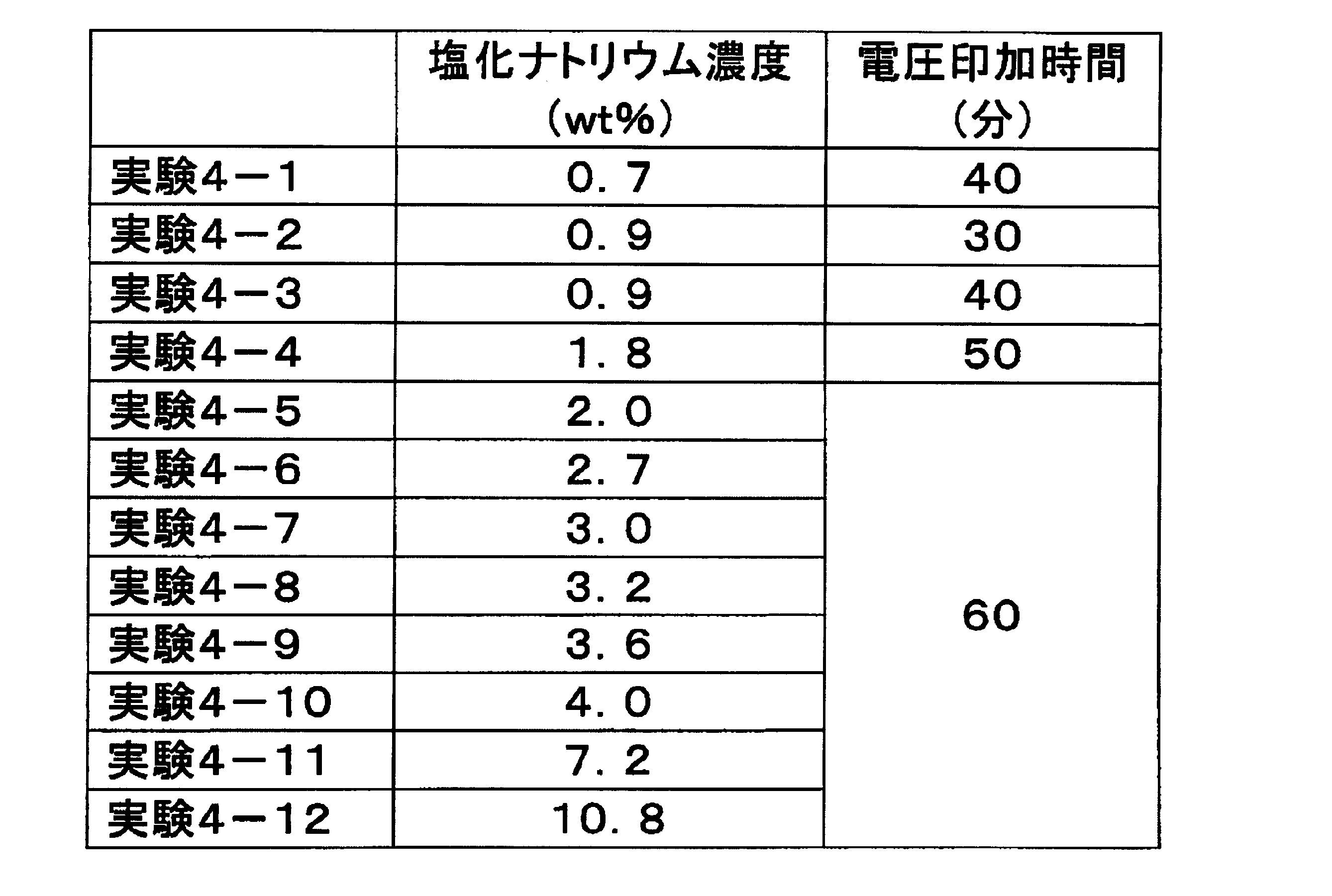
図11に示すように、塩化ナトリウムの濃度が低い範囲にある場合に、遊離塩素濃度の低下が大きかった。塩化ナトリウムの濃度が0.7~3.2wt%の範囲(特に0.7~3.0wt%の範囲)にある場合には、遊離塩素濃度が大きく低下した。なお、1wt%の塩化ナトリウム水溶液1Lには、おおよそ、(10/58.4)=0.171モル(171ミリモル)の塩素イオンが含まれると考えることができる。それに基づいて塩素イオン濃度で考えると、塩素イオン濃度が120ミリモル/L~548ミリモル/Lの範囲(特に、120ミリモル/L~514ミリモル/Lの範囲)にある場合には、遊離塩素濃度が大きく低下した。
(実施例5)
実施例5では、陽極を変えて実施例4と同様の実験を行った。実施例5では、塩化ナトリウム水溶液の濃度を、0.9wt%~3.6wt%の範囲(具体的には0.9wt%、1.35wt%、1.8wt%、および3.6wt%)で変化させ、工程(ii)において60分間の電圧印加を行った。これら以外は、実施例4と同じ条件で実験を行った。
実施例5では、陽極を変えて実施例4と同様の実験を行った。実施例5では、塩化ナトリウム水溶液の濃度を、0.9wt%~3.6wt%の範囲(具体的には0.9wt%、1.35wt%、1.8wt%、および3.6wt%)で変化させ、工程(ii)において60分間の電圧印加を行った。これら以外は、実施例4と同じ条件で実験を行った。
実施例5では、第1の電極21(陽極)として、表面に酸化イリジウムが存在する電極を用いた。具体的には、ペルメレック電極株式会社製の電極(JP-330)を用いた。電極対のうち、陽極以外の部分は実施例1の電極対と同じ構成とした。
実施例5の結果を図12に示す。なお、図12には、比較のために実施例4の結果もあわせて示す。図12に示すように、酸化イリジウムが表面に存在する陽極を用いた実施例5では、塩化ナトリウム濃度が約1.5wt%よりも低い場合に遊離塩素濃度を大きく低減できた。一方、表面に白金が存在する陽極を用いた実施例4では、塩化ナトリウム濃度が約3.4%よりも低い場合に遊離塩素濃度を大きく低減できた。これらの結果は、表面に白金が存在する電極を陽極として用いることによって、幅広い塩濃度の水溶液中の遊離塩素濃度を効率的に低減できることを示唆している。
(実施例6)
実施例6では、図4に示した電解槽211と同様の通液型の電解槽を用いて、遊離塩素濃度の増加および低下させる実験を行った。電極対には、実施例1で用いた電極と同じ電極対を用いた。
実施例6では、図4に示した電解槽211と同様の通液型の電解槽を用いて、遊離塩素濃度の増加および低下させる実験を行った。電極対には、実施例1で用いた電極と同じ電極対を用いた。
水溶液には、濃度が0.9wt%の塩化ナトリウム水溶液(生理食塩水)を用いた。この水溶液200mLを、電解槽を含む循環流路において循環させた。そして、その状態で工程(i)および(ii)を行った。工程(i)では、第1の電極21(陽極)と第2の電極22(陰極)との間に2Aの定電流が流れるように4分間電圧を印加した。この電圧印加によって、水溶液中の遊離塩素濃度が200mg/L前後となった。次の工程(ii)では、第1の電極21(陽極)と第2の電極22(陰極)との間に1.2Vの電圧を60分間印加した。
実施例6では、電解槽内の水溶液の平均流量を、150mL/分、400mL/分、および800mL/分として工程(i)および(ii)を行った。これらの流量はそれぞれ、電解槽内の平均流速に換算すると、1.3mm/秒、3.5mm/秒、および7.1mm/秒に相当する。工程(ii)の電圧印加後の遊離塩素濃度を、図13に示す。図13に示すように、流速が大きいほど遊離塩素濃度が大きく低下する傾向が見られた。具体的には、流速が3.5mm/秒以上であると遊離塩素濃度が大きく低下した。
(実施例7)
実施例7では、第2の陰極の表面積を第1の陰極の表面積よりも大きくした一例について説明する。実施例7で用いた電極ユニット140の構成を、図14に模式的に示す。さらに、実施例7で用いた電解槽を図15に模式的に示す。
実施例7では、第2の陰極の表面積を第1の陰極の表面積よりも大きくした一例について説明する。実施例7で用いた電極ユニット140の構成を、図14に模式的に示す。さらに、実施例7で用いた電解槽を図15に模式的に示す。
図14の電極ユニット140は、第1の電極141、第2の電極142、第3の電極143、およびスペーサ23を含む。第1~第3の電極141~143はそれぞれ、同じネット状電極からなる。ただし、それらの電極が含むネット状電極の枚数は異なる。第1の電極141は、3枚のネット状電極によって構成した。第2の電極142は、4枚のネット状電極によって構成した。第3の電極143は、22枚のネット状電極によって構成した。なお、図14および図15では、図示を容易にするため、第3の電極143を構成するネット状電極の枚数を少なくしている。各ネット状電極には、サイズが80mm×60mmで厚さが0.5mmの白金コート電極を用いた。スペーサ23には、サイズが80mm×60mmで厚さが0.5mmである樹脂製のネット状スペーサを用いた。
図15に示すように、水溶液が流れる方向に対して各ネット状電極が平行になるように、電極ユニット140を槽211内に配置した。そして、流入口211aおよび流出口211bを含む循環路を形成し、その循環路に食塩水1.5L配置して循環させた。食塩水には、遊離塩素濃度が約240~250ppm(≒240~250mg/L)であり且つNaClの濃度が0.65wt%である食塩水を用いた。循環路を流れる食塩水の流量は、0.3L/分とした。そして、食塩水を循環させた状態で工程(ii)を行った。
実施例7では、第2の陽極の表面積と第2の陰極の表面積との比を変えて工程(ii)を行った。各実験における電極の面積比を表3に示す。

実験7-1では、電極ユニット140の第1の電極141を第2の陽極とし、第2の電極142および第3の電極143を第2の陰極とした。この場合、(第2の陰極の表面積)/(第2の陽極の表面積)=26/3となる。すなわち、第2の陰極の表面積は、第2の陽極の表面積の約9倍である。実験7-3では、第1の電極141を第2の陽極とし、第2の電極142を第2の陰極とし、第3の電極143には電圧を印加しなかった。実験7-2では、電極ユニット140の第3の電極143を構成するネット状電極の枚数を12枚としたことを除いて実験7-1と同様に実験を行った。実験7-2では、第3の電極143を構成するネット状電極の枚数を減らしたことによって電極ユニットが薄くなり、槽211内に空間が生じる。実験7-2では、その空間に食塩水の流れが集中することを防止するため、その空間にスペーサ23を配置した。
実験7-1~7-3における遊離塩素濃度の変化を図16に示す。図16に示すように、(第2の陰極の表面積)/(第2の陽極の表面積)の値を大きくするほど、遊離塩素濃度の低下速度が大きくなった。なお、第3の電極143を含む電極ユニットを用いて工程(i)を行う場合、第3の電極143には電圧を印加せずに工程(i)を行ってもよい。たとえば、第1の電極141を第1の陽極とし第2の電極142を第1の陰極として、工程(i)を行ってもよい。
(実施例8)
実施例8では、工程(i)および(ii)を行って遊離塩素濃度の変化を測定した。実施例8の工程(ii)では、電極間に印加する電圧を段階的に小さくした。実施例8では、実施例7の実験7-1と同様の電極ユニットおよび循環路を用いた。この循環路にNaClの濃度が0.65wt%である食塩水を配置して循環させ、その状態で工程(i)および(ii)を行った。
実施例8では、工程(i)および(ii)を行って遊離塩素濃度の変化を測定した。実施例8の工程(ii)では、電極間に印加する電圧を段階的に小さくした。実施例8では、実施例7の実験7-1と同様の電極ユニットおよび循環路を用いた。この循環路にNaClの濃度が0.65wt%である食塩水を配置して循環させ、その状態で工程(i)および(ii)を行った。
工程(i)では、第1の陽極と第1の陰極との間に6Vの直流電圧を印加した。工程(ii)では、第2の陽極と第2の陰極との間に印加する直流電圧の大きさを、最初は2Vとし、次に、1.5Vとし、次に1.2Vとした。遊離塩素濃度の変化を図17Aに示す。また、図17Aの一部拡大図を図17Bに示す。
電極間に6Vの直流電圧を印加する工程(i)では、図17Aに示すように、遊離塩素濃度が上昇する。電極間に2Vの直流電圧を印加する工程(ii)を開始すると、図17Aに示すように、遊離塩素濃度が低下する。しかし、2Vの直流電圧の印加を続けると、図17Bに示すように、遊離塩素濃度が8~9ppm以下には低下しなくなる。ここで、印加電圧を1.5Vに変更すると、再び遊離塩素濃度が低下する。しかし、1.5Vの直流電圧の印加を続けると、図17Bに示すように、遊離塩素濃度が4~5ppm以下には低下しなくなる。ここで、ここで、印加電圧を1.2Vに変更すると、再び遊離塩素濃度が低下する。最終的に、遊離塩素濃度は1ppm以下とすることができた。このように、工程(ii)において印加電圧を段階的に小さくすることによって、遊離塩素濃度を短時間に極めて低くすることができた。
なお、実施例8で用いた装置と同様の装置を用い、印加電圧を4Vとして工程(i)を行ったところ、食塩水の遊離塩素濃度が上昇した。
本発明は、遊離塩素濃度を制御する方法および装置、ならびにそれらを用いた殺菌方法および殺菌装置に利用できる。
11、211 槽
12 電源
13 コントローラ
14 ポンプ
20 電極対
21、141 第1の電極
22、142 第2の電極
143 第3の電極
23 スペーサ
30 水溶液
100、200 装置
300 殺菌対象
301 循環路
12 電源
13 コントローラ
14 ポンプ
20 電極対
21、141 第1の電極
22、142 第2の電極
143 第3の電極
23 スペーサ
30 水溶液
100、200 装置
300 殺菌対象
301 循環路
Claims (20)
- 複数の電極を用いて遊離塩素濃度を制御する方法であって、
(i)塩素イオンを含む水溶液中において、第1の陽極の電位と第1の陰極の電位とを調整することによって、前記水溶液中の遊離塩素濃度を上昇させる工程と、
(ii)前記水溶液中において、第2の陽極の電位と第2の陰極の電位とを調整することによって、前記水溶液中の遊離塩素濃度を低下させる工程と、をこの順に含み、
前記(ii)の工程における前記第2の陽極の電位と前記第2の陰極の電位との差が、前記(i)の工程における前記第1の陽極の電位と前記第1の陰極の電位との差よりも小さく、
前記第1の陽極および前記第1の陰極はそれぞれ、前記複数の電極の一部および他の一部によって構成され、
前記第2の陽極および前記第2の陰極はそれぞれ、前記複数の電極の一部および他の一部によって構成される、方法。 - 前記(i)の工程において前記第1の陽極と前記第1の陰極との間に4V以上の直流電圧が印加され、
前記(ii)の工程において前記第2の陽極と前記第2の陰極との間に0.6V~3Vの範囲にある直流電圧が印加される、請求項1に記載の方法。 - 前記第1の陽極、前記第1の陰極、前記第2の陽極、および前記第2の陰極はそれぞれ、表面に白金が存在する電極である、請求項2に記載の方法。
- 前記第2の陰極の表面積が前記第1の陰極の表面積よりも大きく、
前記第2の陰極の表面積が前記第2の陽極の表面積よりも大きい、請求項1~3のいずれか1項に記載の方法。 - 前記複数の電極は、前記第1の陽極として用いられる第1の電極と、前記第1の陰極として用いられる第2の電極と、第3の電極とを含み、
前記(i)の工程において、前記第3の電極には電圧が印加されず、
前記(ii)の工程において、前記第2の陰極の少なくとも一部として前記第3の電極が用いられる、請求項4に記載の方法。 - 前記(i)の工程と前記(ii)の工程との間に、または、前記(ii)の工程の後に、
(x)前記水溶液中において、第3の陽極の電位と第3の陰極の電位とを調整することによって、前記水溶液中の遊離塩素濃度を一定の範囲に維持する工程をさらに含み、
前記第3の陽極および前記第3の陰極はそれぞれ、前記複数の電極の一部および他の一部によって構成される、請求項1~5のいずれか1項に記載の方法。 - 前記(ii)の工程において、前記第2の陽極の電位と前記第2の陰極の電位との差を徐々に小さくする、請求項1~6のいずれか1項に記載の方法。
- 遊離塩素を含む水溶液を用いて殺菌を行う殺菌方法であって、
請求項1~7のいずれか1項に記載の方法を含み、
(I)前記(i)の工程で処理された前記水溶液を用いて殺菌対象を殺菌する工程を含む、殺菌方法。 - 前記(I)の工程の後に、
(II)前記(ii)の工程で処理された前記水溶液を用いて前記殺菌対象を洗浄する工程をさらに含む、請求項8に記載の殺菌方法。 - 前記(i)および(ii)の工程における前記電位の調整が電解槽内で行われ、
前記電解槽と前記殺菌対象との間で前記水溶液を循環させた状態で前記(i)および(ii)の工程が行われる、請求項8または9に記載の殺菌方法。 - 遊離塩素濃度を制御する装置であって、
複数の電極と、
前記複数の電極に電圧を印加するための電源と、
前記電源を制御するためのコントローラとを備え、
前記コントローラは、
(i)塩素イオンを含む水溶液中において、第1の陽極の電位と第1の陰極の電位とを調整することによって、前記水溶液中の遊離塩素濃度を上昇させる工程と、
(ii)前記水溶液中において、第2の陽極の電位と第2の陰極の電位とを調整することによって、前記水溶液中の遊離塩素濃度を低下させる工程と、をこの順に実行し、
前記(ii)の工程における前記第2の陽極の電位と前記第2の陰極の電位との差が、前記(i)の工程における前記第1の陽極の電位と前記第1の陰極の電位との差よりも小さく、
前記第1の陽極および前記第1の陰極はそれぞれ、前記複数の電極の一部および他の一部によって構成され、
前記第2の陽極および前記第2の陰極はそれぞれ、前記複数の電極の一部および他の一部によって構成される、装置。 - 前記(i)の工程において前記第1の陽極と前記第1の陰極との間に4V以上の直流電圧が印加され、
前記(ii)の工程において前記第2の陽極と前記第2の陰極との間に0.6V~3Vの範囲にある直流電圧が印加される、請求項11に記載の装置。 - 前記第1の陽極、前記第1の陰極、前記第2の陽極、および前記第2の陰極はそれぞれ、表面に白金が存在する電極である、請求項12に記載の装置。
- 前記第2の陰極の表面積が前記第1の陰極の表面積よりも大きく、
前記第2の陰極の表面積が前記第2の陽極の表面積よりも大きい、請求項11~13のいずれか1項に記載の装置。 - 前記複数の電極は、前記第1の陽極として用いられる第1の電極と、前記第1の陰極として用いられる第2の電極と、第3の電極とを含み、
前記(i)の工程において、前記第3の電極には電圧が印加されず、
前記(ii)の工程において、前記第2の陰極の少なくとも一部として前記第3の電極が用いられる、請求項14に記載の装置。 - 前記(i)の工程と前記(ii)の工程との間に、または、前記(ii)の工程の後に、前記コントローラは、
(x)前記水溶液中において、第3の陽極の電位と第3の陰極の電位とを調整することによって、前記水溶液中の遊離塩素濃度を一定の範囲に維持する工程をさらに実行し、
前記第3の陽極および前記第3の陰極はそれぞれ、前記複数の電極の一部および他の一部によって構成される、請求項11~15のいずれか1項に記載の装置。 - 前記コントローラは、前記(ii)の工程において、前記第2の陽極の電位と前記第2の陰極の電位との差を徐々に小さくする、請求項11~16のいずれか1項に記載の装置。
- 遊離塩素を含む水溶液を用いて殺菌を行う殺菌装置であって、
請求項11~17のいずれか1項に記載の装置を含み、
前記コントローラは、
(I)前記(i)の工程で処理された前記水溶液を用いて殺菌対象を殺菌する工程を実行する、殺菌装置。 - 前記コントローラは、前記(I)の工程の後に、
(II)前記(ii)の工程で処理された前記水溶液を用いて前記殺菌対象を洗浄する工程をさらに実行する、請求項18に記載の殺菌装置。 - 前記(i)および(ii)の工程において前記電圧の印加が行われる電解槽を含み、
前記電解槽と前記殺菌対象との間で前記水溶液を循環させた状態で前記(i)および(ii)の工程を行う、請求項18または19に記載の殺菌装置。
Priority Applications (3)
| Application Number | Priority Date | Filing Date | Title |
|---|---|---|---|
| EP15745808.4A EP3103771B1 (en) | 2014-02-06 | 2015-01-30 | Method and apparatus for controlling concentration of free chlorine |
| US15/116,114 US10131555B2 (en) | 2014-02-06 | 2015-01-30 | Method and apparatus for controlling concentration of free chlorine, and sterilization method and sterilization apparatus each utilizing said method and said apparatus |
| CN201580007739.8A CN106029581B (zh) | 2014-02-06 | 2015-01-30 | 游离氯浓度的控制方法和控制装置以及使用该方法和装置的杀菌方法和杀菌装置 |
Applications Claiming Priority (4)
| Application Number | Priority Date | Filing Date | Title |
|---|---|---|---|
| JP2014020876 | 2014-02-06 | ||
| JP2014-020876 | 2014-02-06 | ||
| JP2015003886A JP6487217B2 (ja) | 2014-02-06 | 2015-01-13 | 遊離塩素濃度を制御する方法および装置、ならびにそれらを用いた殺菌方法および殺菌装置 |
| JP2015-003886 | 2015-01-13 |
Publications (1)
| Publication Number | Publication Date |
|---|---|
| WO2015119059A1 true WO2015119059A1 (ja) | 2015-08-13 |
Family
ID=53777866
Family Applications (1)
| Application Number | Title | Priority Date | Filing Date |
|---|---|---|---|
| PCT/JP2015/052728 Ceased WO2015119059A1 (ja) | 2014-02-06 | 2015-01-30 | 遊離塩素濃度を制御する方法および装置、ならびにそれらを用いた殺菌方法および殺菌装置 |
Country Status (5)
| Country | Link |
|---|---|
| US (1) | US10131555B2 (ja) |
| EP (1) | EP3103771B1 (ja) |
| JP (1) | JP6487217B2 (ja) |
| CN (1) | CN106029581B (ja) |
| WO (1) | WO2015119059A1 (ja) |
Families Citing this family (9)
| Publication number | Priority date | Publication date | Assignee | Title |
|---|---|---|---|---|
| NO20161570A1 (no) * | 2016-09-29 | 2018-03-30 | Brage Innovation As | Klorgass-felle for avliving av lakselus parasitter |
| JP6817080B2 (ja) * | 2017-01-13 | 2021-01-20 | カイゲンファーマ株式会社 | 電解用電極 |
| SG10202109754TA (en) * | 2017-03-06 | 2021-10-28 | Evoqua Water Tech Llc | Implementation of feedback control for improved electrochemical system design |
| IL257589A (en) * | 2018-02-18 | 2018-04-30 | Univ Bar Ilan | Method and apparatus for electrochemical ph control |
| KR102313539B1 (ko) * | 2018-11-21 | 2021-10-15 | 이연주 | 살균 전극 및 그 제작 방법 및 이를 이용한 축사 살균 장치 |
| KR102268312B1 (ko) * | 2018-12-13 | 2021-06-23 | 한양대학교 산학협력단 | 재생에너지를 이용하는 차아염소산 생산 장치 |
| JP7516010B2 (ja) * | 2019-02-20 | 2024-07-16 | 東芝ライフスタイル株式会社 | 自律型電気掃除機 |
| CN118984812A (zh) * | 2022-01-14 | 2024-11-19 | 莫雷尔股份有限公司 | 在电解池中产生氯气的方法和设备 |
| CN116479469B (zh) * | 2023-04-23 | 2026-04-17 | 广东美的制冷设备有限公司 | 电解控制方法、可读存储介质、电解控制装置和电解设备 |
Citations (6)
| Publication number | Priority date | Publication date | Assignee | Title |
|---|---|---|---|---|
| JPH11226092A (ja) * | 1998-02-12 | 1999-08-24 | Trp:Kk | 医療用具の殺菌洗浄方法およびその装置 |
| JPH11290855A (ja) * | 1998-04-10 | 1999-10-26 | Trp:Kk | 殺菌洗浄水の供給方法およびその装置 |
| JP2004223419A (ja) * | 2003-01-23 | 2004-08-12 | Fuji Electric Retail Systems Co Ltd | 塩素濃度制御装置 |
| JP2005060761A (ja) * | 2003-08-11 | 2005-03-10 | Dkk Toa Corp | 次亜ハロゲン酸塩発生装置および発生方法 |
| JP2007117882A (ja) * | 2005-10-27 | 2007-05-17 | Takenaka Komuten Co Ltd | 循環水用塩素殺菌システム |
| US20130125316A1 (en) * | 2010-08-02 | 2013-05-23 | Xh20 Solutions Private Limited | System and a Method for Washing, Cleaning, Disinfecting and Sanitizing Laundry Using Electrolytic Cell Having Boron-Doped Diamond Electrode |
Family Cites Families (14)
| Publication number | Priority date | Publication date | Assignee | Title |
|---|---|---|---|---|
| GB1582130A (en) * | 1976-07-13 | 1980-12-31 | Matthey Rustenburg Refines | Electrolytic treatment of effluents |
| US5256268A (en) | 1990-07-18 | 1993-10-26 | Konica Corporation | Water treatment method and apparatus |
| JP3056511B2 (ja) | 1990-07-18 | 2000-06-26 | コニカ株式会社 | 被処理水の処理装置 |
| JP3283052B2 (ja) | 1992-01-08 | 2002-05-20 | クロリンエンジニアズ株式会社 | 次亜塩素酸塩の製造方法 |
| JPH06153744A (ja) * | 1992-09-25 | 1994-06-03 | Riyouyou Sangyo Kk | 魚類寄生虫および細菌の死滅と生簀網付着生物の除去方法 |
| JP3886904B2 (ja) | 2000-12-04 | 2007-02-28 | 株式会社島精機製作所 | 横編機 |
| US6984295B2 (en) * | 2002-02-06 | 2006-01-10 | Luxon Energy Devices Corporation | Electrolytic cell for ozone generation |
| JP4596937B2 (ja) | 2005-03-02 | 2010-12-15 | 英雄 早川 | 次亜塩素酸ナトリウム塩を用いた水の浄化方法 |
| EP1939143A4 (en) * | 2005-09-27 | 2011-05-25 | Tanah Process Ltd | METHOD FOR CONTROLLING ION CONCENTRATION AND APPARATUS THEREFOR |
| KR100849618B1 (ko) * | 2007-02-26 | 2008-08-01 | 한국돌기 주식회사 | 제어된 잔류 염소의 함량을 갖는 살균력이 높은 무취생리식염수의 제조 장치 및 그 제조 방법 |
| JP4980016B2 (ja) * | 2006-09-20 | 2012-07-18 | ペルメレック電極株式会社 | 電解水噴出装置及び殺菌方法 |
| JP2010530794A (ja) * | 2007-02-26 | 2010-09-16 | ドルキー コリア,リミテッド | 低濃度の残留塩素を含有する医療用殺菌生理食塩水の製造方法 |
| CA2710865C (en) * | 2008-01-04 | 2017-06-06 | Puricore, Inc. | A system and method for controlling the generation of a biocidal liquid |
| WO2010027825A2 (en) * | 2008-08-25 | 2010-03-11 | Ceramatec, Inc. | Methods for producing sodium hypochlorite with a three-comportment apparatus containing an acidic anolyte |
-
2015
- 2015-01-13 JP JP2015003886A patent/JP6487217B2/ja active Active
- 2015-01-30 US US15/116,114 patent/US10131555B2/en active Active
- 2015-01-30 CN CN201580007739.8A patent/CN106029581B/zh active Active
- 2015-01-30 EP EP15745808.4A patent/EP3103771B1/en active Active
- 2015-01-30 WO PCT/JP2015/052728 patent/WO2015119059A1/ja not_active Ceased
Patent Citations (6)
| Publication number | Priority date | Publication date | Assignee | Title |
|---|---|---|---|---|
| JPH11226092A (ja) * | 1998-02-12 | 1999-08-24 | Trp:Kk | 医療用具の殺菌洗浄方法およびその装置 |
| JPH11290855A (ja) * | 1998-04-10 | 1999-10-26 | Trp:Kk | 殺菌洗浄水の供給方法およびその装置 |
| JP2004223419A (ja) * | 2003-01-23 | 2004-08-12 | Fuji Electric Retail Systems Co Ltd | 塩素濃度制御装置 |
| JP2005060761A (ja) * | 2003-08-11 | 2005-03-10 | Dkk Toa Corp | 次亜ハロゲン酸塩発生装置および発生方法 |
| JP2007117882A (ja) * | 2005-10-27 | 2007-05-17 | Takenaka Komuten Co Ltd | 循環水用塩素殺菌システム |
| US20130125316A1 (en) * | 2010-08-02 | 2013-05-23 | Xh20 Solutions Private Limited | System and a Method for Washing, Cleaning, Disinfecting and Sanitizing Laundry Using Electrolytic Cell Having Boron-Doped Diamond Electrode |
Non-Patent Citations (1)
| Title |
|---|
| See also references of EP3103771A4 * |
Also Published As
| Publication number | Publication date |
|---|---|
| US20170137305A1 (en) | 2017-05-18 |
| JP6487217B2 (ja) | 2019-03-20 |
| EP3103771B1 (en) | 2022-07-20 |
| CN106029581A (zh) | 2016-10-12 |
| EP3103771A4 (en) | 2017-02-22 |
| JP2015164719A (ja) | 2015-09-17 |
| CN106029581B (zh) | 2019-04-09 |
| US10131555B2 (en) | 2018-11-20 |
| EP3103771A1 (en) | 2016-12-14 |
Similar Documents
| Publication | Publication Date | Title |
|---|---|---|
| JP6487217B2 (ja) | 遊離塩素濃度を制御する方法および装置、ならびにそれらを用いた殺菌方法および殺菌装置 | |
| ES2377945T3 (es) | Método y aparato para producir agua con potencial de oxidación y reducción (ORP) negativo y positivo | |
| JP4627337B2 (ja) | 殺菌方法および殺菌装置 | |
| JP3994418B2 (ja) | イオン濃度調整方法およびイオン濃度調整装置 | |
| JP2001276828A (ja) | 水の電解消毒方法及び電解消毒装置 | |
| JP5678388B1 (ja) | 系に保持されている水性液体のイオン濃度を低減する装置および方法、ならびにその装置を備える装置 | |
| CN105483748A (zh) | 一种消毒液制作设备 | |
| BR112014031544B1 (pt) | Célula de eletrólise monopolar; e método de execução de um processo eletrolítico em uma célula | |
| JP5758099B2 (ja) | 次亜塩素酸水の製造装置及び製造方法 | |
| JPWO2006132160A1 (ja) | 液体のpH調整方法およびpH調整装置 | |
| JP3187690U (ja) | 電解液生成装置 | |
| JP2009279532A (ja) | 二酸化塩素による水処理方法及び装置 | |
| JP4649200B2 (ja) | ラジカル酸素水生成装置及びラジカル酸素水生成システム | |
| JP2012152695A (ja) | 電気分解式塩水滅菌方法及び電気分解式塩水滅菌装置 | |
| JP6536951B2 (ja) | 水性液体の液質を調整するための装置 | |
| JP2003024940A (ja) | 水処理装置 | |
| EP1394119A1 (en) | Method and apparatus for generating ozone by electrolysis | |
| JP6372793B2 (ja) | 水溶液のpHを変化させる方法および装置 | |
| CN110065998B (zh) | 一种抑制溴类副产物生成的饮用水电化学消毒方法 | |
| AU2012201437B2 (en) | Method and apparatus for producing negative and positive oxidative reductive potential (ORP) water | |
| JP2011042855A (ja) | 炭酸水の製造方法および製造装置、ならびに炭酸浴装置 | |
| JP2011078934A (ja) | 銀イオン溶液製造方法及びその装置 | |
| JP2006224082A (ja) | 銅イオン溶液生成法、生成装置および生成水 | |
| WO2014103083A1 (ja) | 清涼飲料水製造原水基準に適合した電解水及び電解水製造方法 | |
| JP2013017405A (ja) | 清涼飲料水製造原水基準に適合した電解水 |
Legal Events
| Date | Code | Title | Description |
|---|---|---|---|
| 121 | Ep: the epo has been informed by wipo that ep was designated in this application |
Ref document number: 15745808 Country of ref document: EP Kind code of ref document: A1 |
|
| WWE | Wipo information: entry into national phase |
Ref document number: 15116114 Country of ref document: US |
|
| NENP | Non-entry into the national phase |
Ref country code: DE |
|
| REEP | Request for entry into the european phase |
Ref document number: 2015745808 Country of ref document: EP |
|
| WWE | Wipo information: entry into national phase |
Ref document number: 2015745808 Country of ref document: EP |