WO2015122245A1 - 産業機械の監視画像表示装置 - Google Patents
産業機械の監視画像表示装置 Download PDFInfo
- Publication number
- WO2015122245A1 WO2015122245A1 PCT/JP2015/051402 JP2015051402W WO2015122245A1 WO 2015122245 A1 WO2015122245 A1 WO 2015122245A1 JP 2015051402 W JP2015051402 W JP 2015051402W WO 2015122245 A1 WO2015122245 A1 WO 2015122245A1
- Authority
- WO
- WIPO (PCT)
- Prior art keywords
- image
- industrial machine
- camera
- displayed
- cameras
- Prior art date
- Legal status (The legal status is an assumption and is not a legal conclusion. Google has not performed a legal analysis and makes no representation as to the accuracy of the status listed.)
- Ceased
Links
Images



Classifications
-
- G—PHYSICS
- G06—COMPUTING OR CALCULATING; COUNTING
- G06V—IMAGE OR VIDEO RECOGNITION OR UNDERSTANDING
- G06V20/00—Scenes; Scene-specific elements
- G06V20/50—Context or environment of the image
- G06V20/56—Context or environment of the image exterior to a vehicle by using sensors mounted on the vehicle
-
- B—PERFORMING OPERATIONS; TRANSPORTING
- B60—VEHICLES IN GENERAL
- B60R—VEHICLES, VEHICLE FITTINGS, OR VEHICLE PARTS, NOT OTHERWISE PROVIDED FOR
- B60R1/00—Optical viewing arrangements; Real-time viewing arrangements for drivers or passengers using optical image capturing systems, e.g. cameras or video systems specially adapted for use in or on vehicles
- B60R1/20—Real-time viewing arrangements for drivers or passengers using optical image capturing systems, e.g. cameras or video systems specially adapted for use in or on vehicles
- B60R1/22—Real-time viewing arrangements for drivers or passengers using optical image capturing systems, e.g. cameras or video systems specially adapted for use in or on vehicles for viewing an area outside the vehicle, e.g. the exterior of the vehicle
- B60R1/23—Real-time viewing arrangements for drivers or passengers using optical image capturing systems, e.g. cameras or video systems specially adapted for use in or on vehicles for viewing an area outside the vehicle, e.g. the exterior of the vehicle with a predetermined field of view
- B60R1/27—Real-time viewing arrangements for drivers or passengers using optical image capturing systems, e.g. cameras or video systems specially adapted for use in or on vehicles for viewing an area outside the vehicle, e.g. the exterior of the vehicle with a predetermined field of view providing all-round vision, e.g. using omnidirectional cameras
-
- E—FIXED CONSTRUCTIONS
- E02—HYDRAULIC ENGINEERING; FOUNDATIONS; SOIL SHIFTING
- E02F—DREDGING; SOIL-SHIFTING
- E02F9/00—Component parts of dredgers or soil-shifting machines, not restricted to one of the kinds covered by groups E02F3/00 - E02F7/00
- E02F9/24—Safety devices, e.g. for preventing overload
-
- E—FIXED CONSTRUCTIONS
- E02—HYDRAULIC ENGINEERING; FOUNDATIONS; SOIL SHIFTING
- E02F—DREDGING; SOIL-SHIFTING
- E02F9/00—Component parts of dredgers or soil-shifting machines, not restricted to one of the kinds covered by groups E02F3/00 - E02F7/00
- E02F9/26—Indicating devices
- E02F9/261—Surveying the work-site to be treated
-
- G—PHYSICS
- G06—COMPUTING OR CALCULATING; COUNTING
- G06T—IMAGE DATA PROCESSING OR GENERATION, IN GENERAL
- G06T11/00—Two-dimensional [2D] image generation
- G06T11/60—Creating or editing images; Combining images with text
-
- G—PHYSICS
- G06—COMPUTING OR CALCULATING; COUNTING
- G06T—IMAGE DATA PROCESSING OR GENERATION, IN GENERAL
- G06T11/00—Two-dimensional [2D] image generation
- G06T11/60—Creating or editing images; Combining images with text
- G06T11/65—Creating or editing images; Combining images with text on geographic maps
-
- H—ELECTRICITY
- H04—ELECTRIC COMMUNICATION TECHNIQUE
- H04N—PICTORIAL COMMUNICATION, e.g. TELEVISION
- H04N23/00—Cameras or camera modules comprising electronic image sensors; Control thereof
- H04N23/90—Arrangement of cameras or camera modules, e.g. multiple cameras in TV studios or sports stadiums
-
- H—ELECTRICITY
- H04—ELECTRIC COMMUNICATION TECHNIQUE
- H04N—PICTORIAL COMMUNICATION, e.g. TELEVISION
- H04N7/00—Television systems
- H04N7/18—Closed-circuit television [CCTV] systems, i.e. systems in which the video signal is not broadcast
- H04N7/181—Closed-circuit television [CCTV] systems, i.e. systems in which the video signal is not broadcast for receiving images from a plurality of remote sources
-
- B—PERFORMING OPERATIONS; TRANSPORTING
- B60—VEHICLES IN GENERAL
- B60R—VEHICLES, VEHICLE FITTINGS, OR VEHICLE PARTS, NOT OTHERWISE PROVIDED FOR
- B60R2300/00—Details of viewing arrangements using cameras and displays, specially adapted for use in a vehicle
- B60R2300/10—Details of viewing arrangements using cameras and displays, specially adapted for use in a vehicle characterised by the type of camera system used
- B60R2300/105—Details of viewing arrangements using cameras and displays, specially adapted for use in a vehicle characterised by the type of camera system used using multiple cameras
-
- B—PERFORMING OPERATIONS; TRANSPORTING
- B60—VEHICLES IN GENERAL
- B60R—VEHICLES, VEHICLE FITTINGS, OR VEHICLE PARTS, NOT OTHERWISE PROVIDED FOR
- B60R2300/00—Details of viewing arrangements using cameras and displays, specially adapted for use in a vehicle
- B60R2300/30—Details of viewing arrangements using cameras and displays, specially adapted for use in a vehicle characterised by the type of image processing
- B60R2300/304—Details of viewing arrangements using cameras and displays, specially adapted for use in a vehicle characterised by the type of image processing using merged images, e.g. merging camera image with stored images
- B60R2300/305—Details of viewing arrangements using cameras and displays, specially adapted for use in a vehicle characterised by the type of image processing using merged images, e.g. merging camera image with stored images merging camera image with lines or icons
-
- B—PERFORMING OPERATIONS; TRANSPORTING
- B60—VEHICLES IN GENERAL
- B60R—VEHICLES, VEHICLE FITTINGS, OR VEHICLE PARTS, NOT OTHERWISE PROVIDED FOR
- B60R2300/00—Details of viewing arrangements using cameras and displays, specially adapted for use in a vehicle
- B60R2300/60—Details of viewing arrangements using cameras and displays, specially adapted for use in a vehicle characterised by monitoring and displaying vehicle exterior scenes from a transformed perspective
- B60R2300/607—Details of viewing arrangements using cameras and displays, specially adapted for use in a vehicle characterised by monitoring and displaying vehicle exterior scenes from a transformed perspective from a bird's eye viewpoint
Definitions
- the present invention relates to an industrial machine monitoring image display device for monitoring the surroundings of an industrial machine such as a large excavator, a dump truck, a road construction machine, etc., particularly for mining.
- a hydraulic excavator has a lower traveling body and an upper revolving body connected to the lower traveling body so as to be pivotable.
- the upper swing body is provided with a front working machine as working means.
- the front work machine includes a boom and an arm, the boom is provided on the upper swing body so as to be able to be lifted and lowered, and the arm is connected to the tip of the boom so as to be rotatable in the vertical direction.
- a front attachment is provided at the tip of the arm.
- a bucket is used as the front attachment when excavation work is performed.
- This surrounding monitoring device is configured by mounting a camera on the upper swing body and installing a monitor at a position in front of a driver's seat where an operator is seated in a driver's cab. The captured image of the camera is displayed on the monitor screen as a video image.
- a surrounding monitoring device is configured by mounting a camera on the upper swing body and installing a monitor at a position in front of a driver's seat where an operator is seated in a driver's cab.
- the captured image of the camera is displayed on the monitor screen as a video image.
- it is also necessary to have visual fields behind the upper revolving structure and on both the left and right sides.
- Japanese Patent Application Laid-Open No. 2004-228688 discloses a configuration in which a peripheral image of an industrial machine acquired by a plurality of cameras is converted to a viewpoint so as to be an upper viewpoint, and is displayed as a planar view monitoring image projected in a plane on a monitor screen.
- a peripheral image of an industrial machine acquired by a plurality of cameras is converted to a viewpoint so as to be an upper viewpoint, and is displayed as a planar view monitoring image projected in a plane on a monitor screen.
- Patent Document 1 in order to obtain a surrounding monitoring image, a plurality of cameras are installed on an upper swing body of a hydraulic excavator, and images from these cameras are combined and displayed on a monitor screen.
- the cameras are installed at three locations, the rear position of the excavator and the left and right side positions, and the optical axes of the imaging lenses of these cameras are directed obliquely downward. Images taken by each camera are through images. In order to obtain a monitoring image, viewpoint conversion processing is performed on the through image. The viewpoint to be converted is an upper viewpoint, and three upper viewpoint images projected from above the hydraulic excavator are thereby obtained.
- the upper viewpoint image is displayed on the monitor screen.
- an illustration image (specifically, a planar illustration image of the hydraulic excavator) symbolized as a hydraulic excavator is displayed on the monitor screen, and the upper image acquired by each camera is displayed.
- the viewpoint image is arranged around the illustration image. More specifically, the illustration image is displayed at the center position of the monitor screen, and the upper viewpoint images are arranged in the rear area and the left and right side areas of the illustration image to display an overhead image for surrounding monitoring.
- hydraulic excavators are also used for mining by mines.
- This mining hydraulic excavator is large, and the lower traveling body is configured as a crawler type having left and right crawler tracks.
- the upper revolving unit mounted on the lower traveling unit via a revolving device is at least 1.8 m above the ground, and the camera provided on the upper revolving unit has a large space at the lower position of the body frame of the upper revolving unit.
- An operator who works around the hydraulic excavator may have entered the lower part of the body frame of the upper swing body, but may not be able to grasp the field of view of the camera for surrounding monitoring.
- the present invention has been made in view of the above points, and an object of the present invention is to expand the visual field range by the surveillance camera and increase the effectiveness of the surrounding monitoring.
- the present invention is provided in an industrial machine having a movable mechanism at least in part, and has a visual field around the periphery of the industrial machine.
- Image display means for displaying the planar image so as to partially include a portion hidden inside the display area of the icon image It is to its said.
- the monitoring image display device for an industrial machine is a device for confirming the surrounding safety during operation of the industrial machine, and the industrial machine has a movable mechanism at least partially. Specifically, they are working means, traveling means, and the like. In order to perform the safe operation
- the image is displayed on an image display means, that is, a monitor.
- a plane image of the industrial machine is displayed as an icon image.
- the icon image is represented by a contour line.
- the image from the surveillance camera is displayed along with the icon image. Therefore, the image of the surveillance camera is a planar view image.
- the surveillance camera is arranged at a high place so that the optical axis is directed downward, whereby a planar view image is obtained.
- At least one or a plurality of surveillance cameras are provided, and preferably four or more surveillance cameras are installed in order to photograph the entire periphery of the industrial machine. When a plurality of surveillance cameras are arranged so that their fields of view overlap each other and are displayed, the images are cut out to provide continuity between adjacent images.
- a space is created at the lower position of its outer shape.
- a catwalk is provided for an operator or the like to pass through.
- the catwalk projects outward from the frame of the upper swing body as a structure.
- an image of a part hidden inside the icon image is displayed.
- the surveillance camera to a high position relative to the parts that make up the machine exterior, such as a catwalk. Moreover, the surveillance camera is arranged at a position protruding outward with respect to the outline of the structure. As a result, the ground surface image can be displayed up to the part inside the outer shape. In order to expand the field of view to the inner side, the position of the camera is higher than the part that defines the outer shape, and the protruding length from the outer shape portion is made longer. However, if the amount of upward and lateral protrusion is increased, the possibility of collision with another object increases accordingly. Therefore, there is a limit to the amount of protrusion.
- the turning radius of the upper swinging body is the limit position of the protruding length of the camera mounting position.
- the limit position of the protruding length of the camera mounting position can be set within the turning radius of the upper turning body.
- the length of the support arm may be adjustable.
- a front working machine is provided as a working means for excavating earth and sand in the upper swing body.
- the front work machine includes a boom provided on the swing frame of the upper swing body so as to be able to be raised and lowered, an arm that can be pivoted in the vertical direction at the tip of the boom, and a bucket that is connected to the tip of the arm via an articulation mechanism. Composed. At the time of excavation, the bucket is bitten into the ground. Therefore, the part where the bucket contacts the ground during excavation is a dangerous area, and it is necessary to prevent other vehicles and workers from entering.
- FIGS. 1 to 3 show a configuration of a hydraulic excavator 1 as an example of an industrial machine.
- 1 is a front view of the excavator 1
- FIG. 2 is a plan view
- FIG. 3 is a left side view.
- the front working machine 5 mentioned later is abbreviate
- the hydraulic excavator 1 has a lower traveling body 2 having a crawler type traveling means, and an upper revolving body 3 installed on the lower traveling body 2 so as to be capable of swiveling.
- the upper swing body 3 is provided with a driver's cab 4 for an operator to board and operate the machine, and a front work machine 5 as work means for performing work such as excavation of earth and sand.
- a front work machine 5 as work means for performing work such as excavation of earth and sand.
- the movable mechanism of the hydraulic excavator 1 is operated by an operator, and the cab 4 is mounted at a position in front of the upper swing body 3.
- the front work machine 5 is provided in a substantially lined position.
- the cab 4 of the upper swing body 3 and the building 6 constituting the machine room are provided at the rear of the front work machine 5. These constitute the swivel body 3a.
- a counterweight 7 is installed at the rearmost end.
- the front work machine 5 includes a boom that can be raised and lowered on the swing body 3a of the upper swing body 3, an arm that is connected to the tip of the boom so as to be vertically movable,
- the boom, the arm, and the bucket are driven by a hydraulic cylinder.
- the specific configuration of the front work machine 5 is a conventionally known configuration.
- the revolving unit body 3a is further provided with a ladder 13 for an operator to get on and off the cab 4 and also includes a catwalk 14 constituting a passage.
- the catwalk 14 is a side portion of the swing body 3a, and is disposed so as to protrude laterally at an intermediate position in the height direction.
- the lower position of the catwalk 14 is a space.
- the ladder 13 is arranged so as to continue to the catwalk 14.
- the revolving body main body 3a has a frame structure, and the catwalk 14 and the ladder 13 are protruding portions from the revolving body main body 3a.
- the hydraulic excavator 1 has the above-described movable mechanism, and a surrounding monitoring device is provided for ensuring the surrounding safety when the movable mechanism is operated.
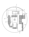
- the surroundings monitoring device is provided on the upper swing body 3 and is composed of a plurality of video cameras capable of moving image shooting. 4 and 5, 15F is a front camera, 15B is a rear camera, and 15L and 15R are left and right side cameras. The surroundings of the excavator 1 are monitored by these cameras 15F, 15B, 15L, and 15R.
- reference numeral 15 is used when generically referring to cameras for camera monitoring.
- the cameras 15F, 15B, 15L, and 15R are provided in the revolving body main body 3a of the upper revolving body 3, and these are arranged at high places, and their optical axes are directed downward or obliquely downward. That is, as shown in FIG. 4, the image obtained by each camera 15 is a planar view image looking down from above.
- the arrangement positions of the respective cameras 15 are set so as to have a positional relationship in which the entire circumference of the excavator 1 can be monitored.
- FIG. 5 shows an example of the arrangement of the cameras 15F, 15B, 15L, and 15R.
- the images acquired by the cameras 15F, 15B, 15L, and 15R are displayed on the monitor 20 as image display means as shown in FIG.
- the monitor 20 is disposed in the cab 4 at a position where the operator can see from the driver's seat where the operator sits and operates the excavator 1.
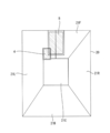
- the images from the cameras 15F, 15B, 15L, and 15R displayed on the monitor 20 are planar images, and the screen of the monitor 20 is divided into a plurality of regions so that the above-described planar images are in a predetermined range.
- the camera images 21F, 21B, 21L, and 21R are displayed in the display areas set on the monitor 20.
- a display area for the icon image 21C is set.
- a planar image of the excavator 1 is symbolized and displayed as shown in FIG.
- the icon image 21C is a simplified hydraulic excavator as an industrial machine to be monitored.
- the upper swing body 3, the front working machine 5 and the catwalk 14 of the hydraulic excavator 1 are displayed.
- FIG. 8 shows the configuration of the display controller 30 that controls the display of images on the monitor 20.
- the display controller 30 includes an image correction unit 31, and camera images input from the cameras 15F, 15B, 15L, and 15R are corrected by the image correction unit 31 based on camera optical system parameters and the like.
- the image quality of each input image is improved by performing normal image signal processing such as correction and color correction.
- the display controller 30 includes an image cutout processing unit 32, and the cameras acquired by the cameras 15F, 15B, 15L, and 15R, respectively.
- the images 21F, 21B, 21L, and 21R are cut out to have sizes and shapes that can be displayed in the respective display areas.
- the icon image 21 is displayed on the monitor 20 together with the four camera images 21F, 21B, 21L, and 21R.
- the icon image 21C is created by the icon image creation unit 33. Then, the camera image 21F, 21B, 21L, 21R and the icon image 21C are combined and displayed by the image combining unit 33.
- the icon image 21C is displayed at the center position of the monitor 20, and the camera images 21F, 21B, 21L, and 21R are arranged around the icon image 21C.
- the output data of the image synthesizing unit 34 is input to the display image generating unit 35, and the images described above are assigned to the respective positions and displayed by the output from the display image generating unit 34.
- the icon image 21 ⁇ / b> C is also an image obtained by planarizing the excavator 1. Accordingly, the monitor 20 displays the excavator 1 and its surroundings in a planar state, so that the operator can easily recognize the situation when the excavator 1 is in operation.
- the camera 15 provided on the upper swing body 3 may have various members and mechanisms such as shields located in the optical path to the ground. Therefore, an image at a position below these shields cannot be obtained.
- a large space is provided at the lower position of the cab 4 between the ground of the crawler belt 2 constituting the ground contact surface of the lower traveling body 2.
- a catwalk 14 and a ladder 13 are provided on the rear side of the cab 4, and there is a wide space below the lower part. In these spaces, when the upper revolving unit 3 is viewed in plan, there are wide hidden portions due to the cab 4, the catwalk 14, the ladder 13, and the like.
- the operator and other workers may enter the hidden space, but also tools and other equipment may be arranged. In some cases, there is room for vehicles to enter. Therefore, from the viewpoint of monitoring the periphery of the hydraulic excavator 1, it is desired that the space of the hidden portion described above be captured within the visual field of the monitoring camera.
- the camera 15L for photographing this area is not attached to the revolving body 3a, but is provided with a support arm 40L that protrudes laterally from the revolving body 3a. Is supported at the tip of the support arm 40L. Accordingly, the optical axis of the camera 15L attached to the support arm 40L is positioned outside the outer end of the catwalk 14 by the dimension p. Moreover, the camera 15L is at a height higher than the ground by a height h. Therefore, at the height position near the ground surface and in the vicinity thereof, the camera 15L is allowed to enter the position of the crawler track that substantially constitutes the lower traveling body 2. Can do. In addition, since the camera 15L is disposed in front of the position of the catwalk 14 to which the ladder 13 is attached, the lower position of the catwalk 14 can also be taken into view.
- the right side camera 15R and the front camera 15F are mounted on the support arms 40R and 40F projecting in a predetermined direction from the revolving body 3a, and the field of view of these parts can be widened.
- the character image 21 ⁇ / b> C is displayed in a transmissive state by an amount corresponding to the expanded visual field range.
- the reference numeral 40 is used to collectively refer to the support arm.
- the hidden part of the upper revolving unit 3 can be placed in the field of view.
- the mounting position and the protruding length of the support arm 40 can be appropriately determined according to the configuration of the upper swing body 3, but the protruding length is based on the turning radius R shown in FIG. If it is inside the turning radius R, there is no fear of colliding with other objects even if it protrudes greatly from the turning body 3a.
- the support arm 40 is preferably formed of a rigid body, and the camera 15 is firmly fixed so that the support arm 40 is not displaced due to vibration or the like.
- the support arm 40L of the camera 15L provided on the left side surface extends sideways, and the support arms of the camera 15F and camera 15R extend 40F and 40R forward.
- the extending direction is provided based on the position of the hidden portion displayed on the monitor 20.
- no special support arm is provided at the upper position of the counterweight 7.
- the camera 15B can also be supported by a support arm.
- the display through the hidden part is a portion where a person or the like may enter, for example, a person such as a ground contact surface of a crawler track may enter. Therefore, the height position and the protruding length of the support arm 40 to which the camera 15 is attached are appropriately set based on the position and spread of the hidden portion where the transparent display needs to be performed. It ’s fine.
- the excavator 1 performs work such as excavation of earth and sand, and the front work machine 5 operates.
- the front work machine 5 since the bucket provided at the tip of the machine operates so as to cut from the upper side toward the earth and sand, if a person or an object is located in the movable trajectory range of the bucket, There is a possibility of collision. It is necessary to protect the front work machine 5 from colliding with a person or an object during this work. Of course, the movement of the front work machine can be visually recognized by the operator boarding the cab 4. Therefore, as shown in FIG. 10, in the reach range of the front work machine 5, the range in which the bucket may be grounded is displayed on the monitor 20 as the excavable range B.
- the front work machine 5 is provided in the upper swing body 3, and when the upper swing body 3 is turned, the front work machine 5 is also turned in synchronization. Since the monitoring cameras 15F, 15B, 15L, and 15R are also provided in the upper swing body 3, the positional relationship with respect to the front work machine 5 on the image by these cameras 15F, 15B, 15L, and 15R does not change. Accordingly, the monitor 20 displays the excavable range B where the front work machine 5 may be grounded together with the camera images 21F, 21B, 21L, and 21R centered on the icon image 21C. It is determined by the width dimension and its maximum reach length. Since there are a plurality of types of buckets having different width dimensions, it is desirable to change the excavable range B according to the configuration of the front work machine 5 actually mounted on the hydraulic excavator 12.
- the excavator 1 can be driven on the basis of the excavable range B when traveling and turning and selecting the excavation location, The position of the excavation point can be easily adjusted. Accordingly, by displaying the excavable range B on the monitor 20, not only can work safety be ensured, but work efficiency is also improved.
Landscapes
- Engineering & Computer Science (AREA)
- Multimedia (AREA)
- Structural Engineering (AREA)
- Mining & Mineral Resources (AREA)
- Civil Engineering (AREA)
- General Engineering & Computer Science (AREA)
- Physics & Mathematics (AREA)
- General Physics & Mathematics (AREA)
- Theoretical Computer Science (AREA)
- Signal Processing (AREA)
- Mechanical Engineering (AREA)
- Component Parts Of Construction Machinery (AREA)
- Closed-Circuit Television Systems (AREA)
Abstract
Description
2 下部走行体
3 上部旋回体
3a 旋回体本体
4 運転室
5 フロント作業機
15,15F,15B,15L,15R カメラ
20 モニタ
21,21F,21B,21L,21R カメラ画像
21C アイコン画像
Claims (3)
- 少なくとも一部に可動機構を有する産業機械(1)に設けられ、この産業機械(1)の周囲を視野とし、少なくとも一部が外形領域から突出した位置に設けた1または複数の監視用カメラ(15,15F,15B,15L,15R)、
前記監視用カメラ(15,15F,15B,15L,15R)により上方から見下ろした平面視画像を生成する画像生成手段(35)と、
前記産業機械(1)の平面であって、少なくとも輪郭線が図形化されたアイコン画像(21C)を作成するアイコン画像生成手段(33)と、
前記画像生成手段(35)により取得した画像を前記アイコン画像生成手段(33)により作成した前記アイコン画像(21C)の周囲に表示するように合成処理を行う画像合成手段(34)と、
画像合成手段により合成された前記平面視画像が、前記アイコン画像(21C)の表示領域の内側に隠れている部位を部分的に含むように表示する画像表示手段(20)と
を備えた産業機械の監視画像表示装置。 - 前記産業機械(1)は旋回可能なフレーム(3)を有するものであって、前記アイコン画像(21C)は前記フレーム(3)及びこのフレーム(3)から外方への突出部を含む領域を輪郭線で表示したものであり、前記監視用カメラ(15)は、前記輪郭線を構成する部位より上方位置であって、この輪郭線より外側に張り出すように設けるようにしたことを特徴とする請求項1記載の産業機械の監視画像表示装置。
- 前記産業機械(1)は、前記フレーム(3)から突出する可動な作業手段(5)を有するものであり、前記アイコン画像(21C)は、前記作業手段(5)の移動軌跡を表示する可動域表示部(B)を有するものである請求項1記載の産業機械の表示装置。
Priority Applications (6)
| Application Number | Priority Date | Filing Date | Title |
|---|---|---|---|
| CA2923033A CA2923033C (en) | 2014-02-17 | 2015-01-20 | Hydraulic excavator |
| US14/916,058 US20160217331A1 (en) | 2014-02-17 | 2015-01-20 | Monitoring image display device of industrial machine |
| CN201580001771.5A CN105493503B (zh) | 2014-02-17 | 2015-01-20 | 液压挖掘机 |
| EP15748978.2A EP3110142B1 (en) | 2014-02-17 | 2015-01-20 | Monitoring image display device of industrial machine |
| AU2015216409A AU2015216409B2 (en) | 2014-02-17 | 2015-01-20 | Monitoring image display device of industrial machine |
| US16/158,346 US10650251B2 (en) | 2014-02-17 | 2018-10-12 | Monitoring image display device of industrial machine |
Applications Claiming Priority (2)
| Application Number | Priority Date | Filing Date | Title |
|---|---|---|---|
| JP2014027536A JP6095592B2 (ja) | 2014-02-17 | 2014-02-17 | 油圧ショベルの監視画像表示装置 |
| JP2014-027536 | 2014-02-17 |
Related Child Applications (2)
| Application Number | Title | Priority Date | Filing Date |
|---|---|---|---|
| US14/916,058 A-371-Of-International US20160217331A1 (en) | 2014-02-17 | 2015-01-20 | Monitoring image display device of industrial machine |
| US16/158,346 Continuation US10650251B2 (en) | 2014-02-17 | 2018-10-12 | Monitoring image display device of industrial machine |
Publications (1)
| Publication Number | Publication Date |
|---|---|
| WO2015122245A1 true WO2015122245A1 (ja) | 2015-08-20 |
Family
ID=53799993
Family Applications (1)
| Application Number | Title | Priority Date | Filing Date |
|---|---|---|---|
| PCT/JP2015/051402 Ceased WO2015122245A1 (ja) | 2014-02-17 | 2015-01-20 | 産業機械の監視画像表示装置 |
Country Status (7)
| Country | Link |
|---|---|
| US (2) | US20160217331A1 (ja) |
| EP (1) | EP3110142B1 (ja) |
| JP (1) | JP6095592B2 (ja) |
| CN (1) | CN105493503B (ja) |
| AU (1) | AU2015216409B2 (ja) |
| CA (1) | CA2923033C (ja) |
| WO (1) | WO2015122245A1 (ja) |
Cited By (5)
| Publication number | Priority date | Publication date | Assignee | Title |
|---|---|---|---|---|
| WO2019077993A1 (ja) * | 2017-10-17 | 2019-04-25 | 株式会社タダノ | 作業車両 |
| JP2019075712A (ja) * | 2017-10-17 | 2019-05-16 | 株式会社タダノ | 作業車両 |
| JP2019075711A (ja) * | 2017-10-17 | 2019-05-16 | 株式会社タダノ | 作業車両 |
| JP2020112030A (ja) * | 2015-03-31 | 2020-07-27 | 株式会社小松製作所 | 油圧ショベル |
| JP2023090535A (ja) * | 2021-12-17 | 2023-06-29 | 日立建機株式会社 | ショベル向け周囲監視システム |
Families Citing this family (26)
| Publication number | Priority date | Publication date | Assignee | Title |
|---|---|---|---|---|
| US9871968B2 (en) * | 2015-05-22 | 2018-01-16 | Caterpillar Inc. | Imaging system for generating a surround-view image |
| JP6713190B2 (ja) * | 2015-10-09 | 2020-06-24 | 住友重機械工業株式会社 | ショベル操作装置及びショベル操作方法 |
| JP2017082415A (ja) * | 2015-10-23 | 2017-05-18 | 株式会社小松製作所 | 表示システム |
| JP2017081238A (ja) * | 2015-10-23 | 2017-05-18 | 株式会社小松製作所 | 表示システムおよび作業車両 |
| EP3399111B1 (en) | 2015-12-28 | 2020-04-15 | Sumitomo (S.H.I.) Construction Machinery Co., Ltd. | Shovel |
| EP3246474B1 (en) * | 2016-03-29 | 2021-11-10 | Komatsu Ltd. | Work vehicle |
| JP6684682B2 (ja) * | 2016-08-18 | 2020-04-22 | 株式会社神戸製鋼所 | 建設機械 |
| US10070071B2 (en) * | 2016-08-30 | 2018-09-04 | Caterpillar Inc. | Method of imaging a machine environment and machine system implementing same |
| JP2018050119A (ja) * | 2016-09-20 | 2018-03-29 | 国立大学法人 東京大学 | 作業車両の表示システム |
| KR102454612B1 (ko) * | 2016-11-01 | 2022-10-13 | 스미토모 겐키 가부시키가이샤 | 건설기계용 안전관리시스템, 관리장치 |
| KR20180078970A (ko) * | 2016-12-30 | 2018-07-10 | 화남전자 주식회사 | 건설장비의 주변부 모니터링을 위한 카메라 배치 구조 |
| US10250812B2 (en) | 2017-05-17 | 2019-04-02 | Caterpillar Inc. | Display system for machine |
| US10889958B2 (en) * | 2017-06-06 | 2021-01-12 | Caterpillar Inc. | Display system for machine |
| CN111032958B (zh) * | 2017-08-08 | 2023-03-10 | 住友建机株式会社 | 道路机械 |
| US10662603B2 (en) * | 2017-08-18 | 2020-05-26 | Independence Excavating, Inc. | Slope roller assembly |
| US10883256B2 (en) * | 2018-05-25 | 2021-01-05 | Deere & Company | Object responsive control system for a work machine |
| CN109255335A (zh) * | 2018-09-28 | 2019-01-22 | 广州希华通讯设备有限公司 | 用于建筑工地挖掘机的识别监控系统 |
| WO2021054756A1 (ko) * | 2019-09-20 | 2021-03-25 | 주식회사 와이즈오토모티브 | 중장비용 전방 영상 생성 장치 |
| WO2021054758A1 (ko) * | 2019-09-20 | 2021-03-25 | 주식회사 와이즈오토모티브 | 건설장비용 전방 영상 생성 장치 |
| WO2021054757A1 (ko) * | 2019-09-20 | 2021-03-25 | 주식회사 와이즈오토모티브 | 건설장비용 전방 영상 생성 장치 |
| US11231501B2 (en) | 2019-09-26 | 2022-01-25 | Baidu Usa Llc | Front and side three-LIDAR design for autonomous driving vehicles |
| JP7491194B2 (ja) * | 2020-11-23 | 2024-05-28 | 株式会社デンソー | 周辺画像生成装置、表示制御方法 |
| CN115013386B (zh) * | 2022-05-30 | 2023-06-23 | 燕山大学 | 基于视觉识别的液压系统防护装置控制方法及其控制装置 |
| US11898332B1 (en) * | 2022-08-22 | 2024-02-13 | Caterpillar Inc. | Adjusting camera bandwidth based on machine operation |
| CN116347240A (zh) * | 2023-01-13 | 2023-06-27 | 北京天玛智控科技股份有限公司 | 煤矿综采工作面的视频监控方法、装置、电子设备和介质 |
| CN121568891A (zh) * | 2023-08-02 | 2026-02-24 | 住友重机械建机起重机株式会社 | 起重机 |
Citations (3)
| Publication number | Priority date | Publication date | Assignee | Title |
|---|---|---|---|---|
| WO2012157438A1 (ja) * | 2011-05-13 | 2012-11-22 | 日立建機株式会社 | 油圧ショベルの後方視野表示装置 |
| JP2012252675A (ja) * | 2011-06-07 | 2012-12-20 | Komatsu Ltd | ダンプトラック |
| JP2013124467A (ja) * | 2011-12-13 | 2013-06-24 | Sumitomo (Shi) Construction Machinery Co Ltd | 建設機械の周囲画像表示装置及び周囲画像表示方法 |
Family Cites Families (15)
| Publication number | Priority date | Publication date | Assignee | Title |
|---|---|---|---|---|
| JP2913230B2 (ja) * | 1991-10-23 | 1999-06-28 | 日立建機株式会社 | 大型建設機械の照明装置 |
| JPH10237900A (ja) * | 1997-02-28 | 1998-09-08 | Hitachi Constr Mach Co Ltd | ラダ−を有する建設機械 |
| JP4196368B2 (ja) * | 1999-12-20 | 2008-12-17 | 株式会社小松製作所 | 建設機械の昇降用ラダー装置 |
| KR100892269B1 (ko) * | 2001-06-15 | 2009-04-09 | 가부시키가이샤 고마쓰 세이사쿠쇼 | 건설기계 |
| JP3980565B2 (ja) * | 2004-02-16 | 2007-09-26 | 松下電器産業株式会社 | 運転支援装置 |
| KR100966288B1 (ko) * | 2009-01-06 | 2010-06-28 | 주식회사 이미지넥스트 | 주변 영상 생성 방법 및 장치 |
| JP4951639B2 (ja) | 2009-03-02 | 2012-06-13 | 日立建機株式会社 | 周囲監視装置を備えた作業機械 |
| JP5269026B2 (ja) * | 2010-09-29 | 2013-08-21 | 日立建機株式会社 | 作業機械の周囲監視装置 |
| EP2631374B1 (en) * | 2010-10-22 | 2020-09-30 | Hitachi Construction Machinery Co., Ltd. | Work machine peripheral monitoring device |
| KR101735116B1 (ko) * | 2011-01-24 | 2017-05-15 | 두산인프라코어 주식회사 | 건설중장비의 운행정보 기록장치 |
| WO2012157379A1 (ja) * | 2011-05-13 | 2012-11-22 | 日立建機株式会社 | 作業機械の周囲監視装置 |
| AU2013208525A1 (en) * | 2012-01-12 | 2014-08-14 | Hitachi Construction Machinery Co., Ltd. | Periphery monitoring device for self-propelled industrial machine |
| JP5988683B2 (ja) * | 2012-05-15 | 2016-09-07 | 日立建機株式会社 | 自走式産業機械の表示装置 |
| JP2013253402A (ja) * | 2012-06-06 | 2013-12-19 | Hitachi Constr Mach Co Ltd | 作業機械の周囲監視装置 |
| CN104380724B (zh) * | 2012-06-08 | 2017-09-12 | 日立建机株式会社 | 自行式工业机械的显示装置 |
-
2014
- 2014-02-17 JP JP2014027536A patent/JP6095592B2/ja active Active
-
2015
- 2015-01-20 EP EP15748978.2A patent/EP3110142B1/en active Active
- 2015-01-20 US US14/916,058 patent/US20160217331A1/en not_active Abandoned
- 2015-01-20 WO PCT/JP2015/051402 patent/WO2015122245A1/ja not_active Ceased
- 2015-01-20 CA CA2923033A patent/CA2923033C/en active Active
- 2015-01-20 CN CN201580001771.5A patent/CN105493503B/zh active Active
- 2015-01-20 AU AU2015216409A patent/AU2015216409B2/en active Active
-
2018
- 2018-10-12 US US16/158,346 patent/US10650251B2/en active Active
Patent Citations (3)
| Publication number | Priority date | Publication date | Assignee | Title |
|---|---|---|---|---|
| WO2012157438A1 (ja) * | 2011-05-13 | 2012-11-22 | 日立建機株式会社 | 油圧ショベルの後方視野表示装置 |
| JP2012252675A (ja) * | 2011-06-07 | 2012-12-20 | Komatsu Ltd | ダンプトラック |
| JP2013124467A (ja) * | 2011-12-13 | 2013-06-24 | Sumitomo (Shi) Construction Machinery Co Ltd | 建設機械の周囲画像表示装置及び周囲画像表示方法 |
Non-Patent Citations (1)
| Title |
|---|
| See also references of EP3110142A4 * |
Cited By (10)
| Publication number | Priority date | Publication date | Assignee | Title |
|---|---|---|---|---|
| JP2020112030A (ja) * | 2015-03-31 | 2020-07-27 | 株式会社小松製作所 | 油圧ショベル |
| JP2021139290A (ja) * | 2015-03-31 | 2021-09-16 | 株式会社小松製作所 | システムおよび方法 |
| JP7108750B2 (ja) | 2015-03-31 | 2022-07-28 | 株式会社小松製作所 | システムおよび方法 |
| WO2019077993A1 (ja) * | 2017-10-17 | 2019-04-25 | 株式会社タダノ | 作業車両 |
| JP2019075712A (ja) * | 2017-10-17 | 2019-05-16 | 株式会社タダノ | 作業車両 |
| JP2019075711A (ja) * | 2017-10-17 | 2019-05-16 | 株式会社タダノ | 作業車両 |
| US10919584B2 (en) | 2017-10-17 | 2021-02-16 | Tadano Ltd. | Work vehicle |
| JP7143578B2 (ja) | 2017-10-17 | 2022-09-29 | 株式会社タダノ | 作業車両 |
| JP2023090535A (ja) * | 2021-12-17 | 2023-06-29 | 日立建機株式会社 | ショベル向け周囲監視システム |
| JP7733563B2 (ja) | 2021-12-17 | 2025-09-03 | 日立建機株式会社 | ショベル向け周囲監視システム |
Also Published As
| Publication number | Publication date |
|---|---|
| AU2015216409B2 (en) | 2017-10-19 |
| CN105493503A (zh) | 2016-04-13 |
| EP3110142A4 (en) | 2017-11-29 |
| JP2015151794A (ja) | 2015-08-24 |
| US20160217331A1 (en) | 2016-07-28 |
| US20190042858A1 (en) | 2019-02-07 |
| CN105493503B (zh) | 2018-08-24 |
| EP3110142A1 (en) | 2016-12-28 |
| CA2923033C (en) | 2021-01-12 |
| CA2923033A1 (en) | 2015-08-20 |
| JP6095592B2 (ja) | 2017-03-15 |
| AU2015216409A1 (en) | 2016-03-17 |
| US10650251B2 (en) | 2020-05-12 |
| EP3110142B1 (en) | 2021-12-22 |
Similar Documents
| Publication | Publication Date | Title |
|---|---|---|
| JP6095592B2 (ja) | 油圧ショベルの監視画像表示装置 | |
| JP6204884B2 (ja) | 旋回式作業機の周囲表示装置 | |
| KR101945421B1 (ko) | 작업 기계의 주변 감시 장치 | |
| JP6106754B2 (ja) | 作業機械の周囲監視装置 | |
| JP6427597B2 (ja) | 作業機械の周辺監視装置及び作業機械の周辺監視方法 | |
| JP6071786B2 (ja) | 作業機械の周囲監視装置 | |
| CN106716988A (zh) | 作业机械的周边监视装置 | |
| WO2016174754A1 (ja) | 作業機械の周辺監視装置及び作業機械の周辺監視方法 | |
| WO2013038874A1 (ja) | 作業機の周囲監視装置 | |
| CN104041018A (zh) | 自行式工业机械的周围监视装置 | |
| CN107406035A (zh) | 工程作业机械 | |
| EP3788205B1 (en) | System and method for selectively displaying image data in a working machine | |
| KR20170024295A (ko) | 작업기계 | |
| JP2006016914A (ja) | 後方監視カメラ装置 | |
| JP6188858B2 (ja) | 作業機械の周囲監視装置 | |
| WO2025084139A1 (ja) | 作業機械および作業システム |
Legal Events
| Date | Code | Title | Description |
|---|---|---|---|
| WWE | Wipo information: entry into national phase |
Ref document number: 201580001771.5 Country of ref document: CN |
|
| 121 | Ep: the epo has been informed by wipo that ep was designated in this application |
Ref document number: 15748978 Country of ref document: EP Kind code of ref document: A1 |
|
| ENP | Entry into the national phase |
Ref document number: 2923033 Country of ref document: CA |
|
| WWE | Wipo information: entry into national phase |
Ref document number: 14916058 Country of ref document: US |
|
| REEP | Request for entry into the european phase |
Ref document number: 2015748978 Country of ref document: EP |
|
| WWE | Wipo information: entry into national phase |
Ref document number: 2015748978 Country of ref document: EP |
|
| ENP | Entry into the national phase |
Ref document number: 2015216409 Country of ref document: AU Date of ref document: 20150120 Kind code of ref document: A |
|
| NENP | Non-entry into the national phase |
Ref country code: DE |