WO2015125430A1 - Procédé de commande de dispositif de stockage d'électricité, dispositif de stockage d'électricité et programme - Google Patents
Procédé de commande de dispositif de stockage d'électricité, dispositif de stockage d'électricité et programme Download PDFInfo
- Publication number
- WO2015125430A1 WO2015125430A1 PCT/JP2015/000511 JP2015000511W WO2015125430A1 WO 2015125430 A1 WO2015125430 A1 WO 2015125430A1 JP 2015000511 W JP2015000511 W JP 2015000511W WO 2015125430 A1 WO2015125430 A1 WO 2015125430A1
- Authority
- WO
- WIPO (PCT)
- Prior art keywords
- power
- storage device
- power storage
- specific area
- mobile terminal
- Prior art date
- Legal status (The legal status is an assumption and is not a legal conclusion. Google has not performed a legal analysis and makes no representation as to the accuracy of the status listed.)
- Ceased
Links
Images




Classifications
-
- B—PERFORMING OPERATIONS; TRANSPORTING
- B62—LAND VEHICLES FOR TRAVELLING OTHERWISE THAN ON RAILS
- B62M—RIDER PROPULSION OF WHEELED VEHICLES OR SLEDGES; POWERED PROPULSION OF SLEDGES OR SINGLE-TRACK CYCLES; TRANSMISSIONS SPECIALLY ADAPTED FOR SUCH VEHICLES
- B62M6/00—Rider propulsion of wheeled vehicles with additional source of power, e.g. combustion engine or electric motor
- B62M6/40—Rider propelled cycles with auxiliary electric motor
- B62M6/45—Control or actuating devices therefor
-
- B—PERFORMING OPERATIONS; TRANSPORTING
- B60—VEHICLES IN GENERAL
- B60L—PROPULSION OF ELECTRICALLY-PROPELLED VEHICLES; SUPPLYING ELECTRIC POWER FOR AUXILIARY EQUIPMENT OF ELECTRICALLY-PROPELLED VEHICLES; ELECTRODYNAMIC BRAKE SYSTEMS FOR VEHICLES IN GENERAL; MAGNETIC SUSPENSION OR LEVITATION FOR VEHICLES; MONITORING OPERATING VARIABLES OF ELECTRICALLY-PROPELLED VEHICLES; ELECTRIC SAFETY DEVICES FOR ELECTRICALLY-PROPELLED VEHICLES
- B60L15/00—Methods, circuits, or devices for controlling the traction-motor speed of electrically-propelled vehicles
- B60L15/02—Methods, circuits, or devices for controlling the traction-motor speed of electrically-propelled vehicles characterised by the form of the current used in the control circuit
- B60L15/08—Methods, circuits, or devices for controlling the traction-motor speed of electrically-propelled vehicles characterised by the form of the current used in the control circuit using pulses
-
- B—PERFORMING OPERATIONS; TRANSPORTING
- B60—VEHICLES IN GENERAL
- B60L—PROPULSION OF ELECTRICALLY-PROPELLED VEHICLES; SUPPLYING ELECTRIC POWER FOR AUXILIARY EQUIPMENT OF ELECTRICALLY-PROPELLED VEHICLES; ELECTRODYNAMIC BRAKE SYSTEMS FOR VEHICLES IN GENERAL; MAGNETIC SUSPENSION OR LEVITATION FOR VEHICLES; MONITORING OPERATING VARIABLES OF ELECTRICALLY-PROPELLED VEHICLES; ELECTRIC SAFETY DEVICES FOR ELECTRICALLY-PROPELLED VEHICLES
- B60L50/00—Electric propulsion with power supplied within the vehicle
- B60L50/20—Electric propulsion with power supplied within the vehicle using propulsion power generated by humans or animals
-
- B—PERFORMING OPERATIONS; TRANSPORTING
- B62—LAND VEHICLES FOR TRAVELLING OTHERWISE THAN ON RAILS
- B62M—RIDER PROPULSION OF WHEELED VEHICLES OR SLEDGES; POWERED PROPULSION OF SLEDGES OR SINGLE-TRACK CYCLES; TRANSMISSIONS SPECIALLY ADAPTED FOR SUCH VEHICLES
- B62M6/00—Rider propulsion of wheeled vehicles with additional source of power, e.g. combustion engine or electric motor
- B62M6/80—Accessories, e.g. power sources; Arrangements thereof
- B62M6/90—Batteries
-
- G—PHYSICS
- G05—CONTROLLING; REGULATING
- G05D—SYSTEMS FOR CONTROLLING OR REGULATING NON-ELECTRIC VARIABLES
- G05D1/00—Control of position, course, altitude or attitude of land, water, air or space vehicles, e.g. using automatic pilots
- G05D1/0011—Control of position, course, altitude or attitude of land, water, air or space vehicles, e.g. using automatic pilots associated with a remote control arrangement
- G05D1/0022—Control of position, course, altitude or attitude of land, water, air or space vehicles, e.g. using automatic pilots associated with a remote control arrangement characterised by the communication link
-
- B—PERFORMING OPERATIONS; TRANSPORTING
- B60—VEHICLES IN GENERAL
- B60L—PROPULSION OF ELECTRICALLY-PROPELLED VEHICLES; SUPPLYING ELECTRIC POWER FOR AUXILIARY EQUIPMENT OF ELECTRICALLY-PROPELLED VEHICLES; ELECTRODYNAMIC BRAKE SYSTEMS FOR VEHICLES IN GENERAL; MAGNETIC SUSPENSION OR LEVITATION FOR VEHICLES; MONITORING OPERATING VARIABLES OF ELECTRICALLY-PROPELLED VEHICLES; ELECTRIC SAFETY DEVICES FOR ELECTRICALLY-PROPELLED VEHICLES
- B60L2200/00—Type of vehicles
- B60L2200/12—Bikes
-
- B—PERFORMING OPERATIONS; TRANSPORTING
- B60—VEHICLES IN GENERAL
- B60L—PROPULSION OF ELECTRICALLY-PROPELLED VEHICLES; SUPPLYING ELECTRIC POWER FOR AUXILIARY EQUIPMENT OF ELECTRICALLY-PROPELLED VEHICLES; ELECTRODYNAMIC BRAKE SYSTEMS FOR VEHICLES IN GENERAL; MAGNETIC SUSPENSION OR LEVITATION FOR VEHICLES; MONITORING OPERATING VARIABLES OF ELECTRICALLY-PROPELLED VEHICLES; ELECTRIC SAFETY DEVICES FOR ELECTRICALLY-PROPELLED VEHICLES
- B60L2240/00—Control parameters of input or output; Target parameters
- B60L2240/60—Navigation input
- B60L2240/62—Vehicle position
- B60L2240/622—Vehicle position by satellite navigation
-
- B—PERFORMING OPERATIONS; TRANSPORTING
- B60—VEHICLES IN GENERAL
- B60L—PROPULSION OF ELECTRICALLY-PROPELLED VEHICLES; SUPPLYING ELECTRIC POWER FOR AUXILIARY EQUIPMENT OF ELECTRICALLY-PROPELLED VEHICLES; ELECTRODYNAMIC BRAKE SYSTEMS FOR VEHICLES IN GENERAL; MAGNETIC SUSPENSION OR LEVITATION FOR VEHICLES; MONITORING OPERATING VARIABLES OF ELECTRICALLY-PROPELLED VEHICLES; ELECTRIC SAFETY DEVICES FOR ELECTRICALLY-PROPELLED VEHICLES
- B60L2240/00—Control parameters of input or output; Target parameters
- B60L2240/60—Navigation input
- B60L2240/68—Traffic data
-
- B—PERFORMING OPERATIONS; TRANSPORTING
- B60—VEHICLES IN GENERAL
- B60L—PROPULSION OF ELECTRICALLY-PROPELLED VEHICLES; SUPPLYING ELECTRIC POWER FOR AUXILIARY EQUIPMENT OF ELECTRICALLY-PROPELLED VEHICLES; ELECTRODYNAMIC BRAKE SYSTEMS FOR VEHICLES IN GENERAL; MAGNETIC SUSPENSION OR LEVITATION FOR VEHICLES; MONITORING OPERATING VARIABLES OF ELECTRICALLY-PROPELLED VEHICLES; ELECTRIC SAFETY DEVICES FOR ELECTRICALLY-PROPELLED VEHICLES
- B60L2240/00—Control parameters of input or output; Target parameters
- B60L2240/70—Interactions with external data bases, e.g. traffic centres
-
- B—PERFORMING OPERATIONS; TRANSPORTING
- B60—VEHICLES IN GENERAL
- B60L—PROPULSION OF ELECTRICALLY-PROPELLED VEHICLES; SUPPLYING ELECTRIC POWER FOR AUXILIARY EQUIPMENT OF ELECTRICALLY-PROPELLED VEHICLES; ELECTRODYNAMIC BRAKE SYSTEMS FOR VEHICLES IN GENERAL; MAGNETIC SUSPENSION OR LEVITATION FOR VEHICLES; MONITORING OPERATING VARIABLES OF ELECTRICALLY-PROPELLED VEHICLES; ELECTRIC SAFETY DEVICES FOR ELECTRICALLY-PROPELLED VEHICLES
- B60L2250/00—Driver interactions
- B60L2250/16—Driver interactions by display
-
- B—PERFORMING OPERATIONS; TRANSPORTING
- B60—VEHICLES IN GENERAL
- B60L—PROPULSION OF ELECTRICALLY-PROPELLED VEHICLES; SUPPLYING ELECTRIC POWER FOR AUXILIARY EQUIPMENT OF ELECTRICALLY-PROPELLED VEHICLES; ELECTRODYNAMIC BRAKE SYSTEMS FOR VEHICLES IN GENERAL; MAGNETIC SUSPENSION OR LEVITATION FOR VEHICLES; MONITORING OPERATING VARIABLES OF ELECTRICALLY-PROPELLED VEHICLES; ELECTRIC SAFETY DEVICES FOR ELECTRICALLY-PROPELLED VEHICLES
- B60L2250/00—Driver interactions
- B60L2250/26—Driver interactions by pedal actuation
-
- B—PERFORMING OPERATIONS; TRANSPORTING
- B60—VEHICLES IN GENERAL
- B60L—PROPULSION OF ELECTRICALLY-PROPELLED VEHICLES; SUPPLYING ELECTRIC POWER FOR AUXILIARY EQUIPMENT OF ELECTRICALLY-PROPELLED VEHICLES; ELECTRODYNAMIC BRAKE SYSTEMS FOR VEHICLES IN GENERAL; MAGNETIC SUSPENSION OR LEVITATION FOR VEHICLES; MONITORING OPERATING VARIABLES OF ELECTRICALLY-PROPELLED VEHICLES; ELECTRIC SAFETY DEVICES FOR ELECTRICALLY-PROPELLED VEHICLES
- B60L2260/00—Operating Modes
- B60L2260/40—Control modes
- B60L2260/50—Control modes by future state prediction
- B60L2260/54—Energy consumption estimation
-
- H—ELECTRICITY
- H01—ELECTRIC ELEMENTS
- H01M—PROCESSES OR MEANS, e.g. BATTERIES, FOR THE DIRECT CONVERSION OF CHEMICAL ENERGY INTO ELECTRICAL ENERGY
- H01M10/00—Secondary cells; Manufacture thereof
- H01M10/42—Methods or arrangements for servicing or maintenance of secondary cells or secondary half-cells
- H01M10/425—Structural combination with electronic components, e.g. electronic circuits integrated to the outside of the casing
- H01M10/4257—Smart batteries, e.g. electronic circuits inside the housing of the cells or batteries
-
- Y—GENERAL TAGGING OF NEW TECHNOLOGICAL DEVELOPMENTS; GENERAL TAGGING OF CROSS-SECTIONAL TECHNOLOGIES SPANNING OVER SEVERAL SECTIONS OF THE IPC; TECHNICAL SUBJECTS COVERED BY FORMER USPC CROSS-REFERENCE ART COLLECTIONS [XRACs] AND DIGESTS
- Y02—TECHNOLOGIES OR APPLICATIONS FOR MITIGATION OR ADAPTATION AGAINST CLIMATE CHANGE
- Y02E—REDUCTION OF GREENHOUSE GAS [GHG] EMISSIONS, RELATED TO ENERGY GENERATION, TRANSMISSION OR DISTRIBUTION
- Y02E60/00—Enabling technologies; Technologies with a potential or indirect contribution to GHG emissions mitigation
- Y02E60/10—Energy storage using batteries
-
- Y—GENERAL TAGGING OF NEW TECHNOLOGICAL DEVELOPMENTS; GENERAL TAGGING OF CROSS-SECTIONAL TECHNOLOGIES SPANNING OVER SEVERAL SECTIONS OF THE IPC; TECHNICAL SUBJECTS COVERED BY FORMER USPC CROSS-REFERENCE ART COLLECTIONS [XRACs] AND DIGESTS
- Y02—TECHNOLOGIES OR APPLICATIONS FOR MITIGATION OR ADAPTATION AGAINST CLIMATE CHANGE
- Y02T—CLIMATE CHANGE MITIGATION TECHNOLOGIES RELATED TO TRANSPORTATION
- Y02T10/00—Road transport of goods or passengers
- Y02T10/60—Other road transportation technologies with climate change mitigation effect
- Y02T10/70—Energy storage systems for electromobility, e.g. batteries
-
- Y—GENERAL TAGGING OF NEW TECHNOLOGICAL DEVELOPMENTS; GENERAL TAGGING OF CROSS-SECTIONAL TECHNOLOGIES SPANNING OVER SEVERAL SECTIONS OF THE IPC; TECHNICAL SUBJECTS COVERED BY FORMER USPC CROSS-REFERENCE ART COLLECTIONS [XRACs] AND DIGESTS
- Y02—TECHNOLOGIES OR APPLICATIONS FOR MITIGATION OR ADAPTATION AGAINST CLIMATE CHANGE
- Y02T—CLIMATE CHANGE MITIGATION TECHNOLOGIES RELATED TO TRANSPORTATION
- Y02T10/00—Road transport of goods or passengers
- Y02T10/60—Other road transportation technologies with climate change mitigation effect
- Y02T10/72—Electric energy management in electromobility
-
- Y—GENERAL TAGGING OF NEW TECHNOLOGICAL DEVELOPMENTS; GENERAL TAGGING OF CROSS-SECTIONAL TECHNOLOGIES SPANNING OVER SEVERAL SECTIONS OF THE IPC; TECHNICAL SUBJECTS COVERED BY FORMER USPC CROSS-REFERENCE ART COLLECTIONS [XRACs] AND DIGESTS
- Y02—TECHNOLOGIES OR APPLICATIONS FOR MITIGATION OR ADAPTATION AGAINST CLIMATE CHANGE
- Y02T—CLIMATE CHANGE MITIGATION TECHNOLOGIES RELATED TO TRANSPORTATION
- Y02T90/00—Enabling technologies or technologies with a potential or indirect contribution to GHG emissions mitigation
- Y02T90/10—Technologies relating to charging of electric vehicles
- Y02T90/16—Information or communication technologies improving the operation of electric vehicles
Definitions
- the present disclosure relates to a method for controlling a power storage device including a storage battery, a power storage device, and a program.
- a storage battery has been used as a power source for an electric vehicle such as an electric assist bicycle.
- a storage battery is used as a power source for driving the motor, and the pedaling force at the pedal is detected by a sensor, and the output power from the storage battery to the motor is controlled based on the detection result. It has been broken.
- the assist drive control device of the electrically assisted bicycle is controlled to assist the pedal depression force.
- an electrically assisted bicycle that changes an auxiliary driving force and gives a warning (for example, Patent Document 1).
- the above control can be executed because the above control is mounted in advance on the electric assist bicycle.
- the control is not installed in advance.
- this subject exists not only in an electrically assisted bicycle but also in an electric vehicle using a storage battery as a driving power source.
- an exemplary embodiment that is not limited provides a method for controlling a power storage device that improves the above-described problem.
- a method for controlling a power storage device is a method for controlling a power storage device that is mounted on an electric vehicle, wherein the electric vehicle is located in a specific area when the electric vehicle is located outside the specific area.
- the power storage apparatus can execute the control of the present disclosure within the specific area. It is possible to reduce the driving force of the electric vehicle.
- FIG. 1 is a schematic diagram of an electrically assisted bicycle in a state where the power storage device according to the first embodiment is mounted.
- the main body frame 501 of the electric assist bicycle 500 includes a front wheel 502, a rear wheel 503, a handle 504, a saddle 505, a pedal 506, a pedaling force detection unit 507, a crank arm 508, a crankshaft 509, an auxiliary power unit 510, and a control unit 511. Installed.
- the pedal 506 is connected to the crankshaft 509 via the crank arm 508.
- the crankshaft 509 is connected to the auxiliary power unit 510.
- the pedaling force is converted into the rotational force of the crankshaft 509 via the crank arm 508 and transmitted to the auxiliary power unit 510.
- a power storage device 300 including a storage battery is detachably mounted at a position below the saddle 505.
- the pedaling force detection unit 507 is configured by using, for example, a pressure sensor and is attached to the pedal 506. Then, the pedaling force detection unit 507 detects the pedaling force generated when the user steps on the pedal 506 in order to row the electric assist bicycle 500.
- the auxiliary power unit 510 is configured using, for example, a motor 512, a gear, a clutch mechanism, or the like.
- the control unit 511 outputs a control signal related to driving of the motor 512 to the auxiliary power unit 510 based on the pedaling force detected by the pedaling force detector 507.
- the auxiliary power unit 510 drives the motor 512 by receiving driving power from the storage battery of the power storage device 300 in response to a control signal from the control unit 511.
- the auxiliary power unit 510 adds the driving force to the rotational force of the crankshaft 509 obtained by the user depressing the pedal 506 by a gear or clutch mechanism, thereby generating the driving force of the rear wheel 503.
- the auxiliary power unit 510 transmits the driving force thus obtained to the rear wheel 503 via the chain 513, for example.
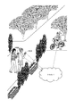
- FIG. 2 is a schematic diagram showing a state where the user is riding and driving the electrically assisted bicycle with the power storage device of FIG. 1 attached.
- the user carries the portable terminal 100 and rides on the electrically assisted bicycle 500 to which the power storage device 300 is detachably attached.
- the mobile terminal 100 is network-connected to a server device or the like in the cloud (computer network) and wirelessly connected to the power storage device 300.
- the mobile terminal 100 acquires map information from the server device in the cloud.
- This map information includes information (hereinafter referred to as “specific area”) of an area (hereinafter referred to as “specific area”) that may collide with a moving body such as a car or a bicycle or a pedestrian, that is, an accident is likely to occur. "Specific area information").
- specific area information include the vicinity of an intersection with a blind spot, a slope with a high speed, an area close to a moving object such as an automobile and a bicycle, or a pedestrian.
- the mobile terminal 100 repeatedly acquires position information indicating the position of the mobile terminal 100 using, for example, GPS (Global Positioning System). Then, the mobile terminal 100 determines whether or not the user is driving the power-assisted bicycle 500 in the specific area from the specific area information and the position information. When the portable terminal 100 determines that the electric assist bicycle 500 is being driven in the specific area, the portable terminal 100 transmits a signal of an output power control command to the power storage device 300 by wireless communication. The power storage device 300 controls the output of driving power from the storage battery to the motor of the electrically assisted bicycle 500 based on the output power control command signal.
- GPS Global Positioning System
- the output power control command in the first embodiment is intermittent from the storage battery of the power storage device 300 to the motor of the electric assist bicycle 500 so that the user can understand that the electric assist bicycle 500 is performing discontinuous operation. It is a command to output driving power automatically.
- the output power control command is such a command, the electrically assisted bicycle 500 performs a discontinuous operation, whereby the user can recognize that the electrically assisted bicycle 500 is being driven in a specific area.
- the intermittent driving power is output, for example, by outputting driving power having a pulse waveform that repeats an on period and an off period.
- the length of the on period and the off period is, for example, a length that allows the user to feel that the electrically assisted bicycle has operated discontinuously. It should be noted that a period in which the output is lower than the on period may be used instead of the off period.
- the output of the intermittent driving power is not limited to the pulse power as described above, as long as the user can understand that the electrically assisted bicycle 500 is operating discontinuously. Good.
- the intermittent output of the driving power is an example of reducing the driving power when the electric vehicle according to the present disclosure is in the specific area as compared to when it is outside the specific area.
- the output of the said intermittent drive electric power is implement
- An FET is exemplified as the switching element.
- the output of the driving power from the storage battery of the power storage device 300 to the motor of the electrically assisted bicycle 500 is intermittent. It doesn't have to be a thing.
- FIG. 3 is a block diagram showing the configuration of the mobile terminal 100 according to the first embodiment.
- the mobile terminal 100 is, for example, a smartphone or a tablet terminal. Assume that pairing is set in advance between the mobile terminal 100 and the power storage device 300. Thereby, when the portable terminal 100 and the power storage device 300 come close to each other, the wireless connection is automatically made, and when the portable terminal 100 and the power storage device 300 are separated from each other, the wireless connection is automatically disconnected.
- the portable terminal 100 includes antennas 101, 102, 103, a storage battery 104, a memory 105, a control unit 106, a network communication unit 107, an inter-device communication unit 108, a GPS unit 109, a display unit 110, and an operation unit 111.
- the storage battery 104 is a power source of each part that requires the power of the mobile terminal 100.
- power lines connecting the storage battery 104 and each unit that requires power are omitted for simplification of the drawing.
- the memory 105 is a memory for storing various control programs or various application programs.
- the control unit 106 performs various controls and various calculations of the mobile terminal 100 as a whole, and temporarily stores, for example, information acquired from the outside, intermediate results of the calculation, or final results in the memory 105.
- the control part 106 in 1st Embodiment performs the storage battery output control process later mentioned with reference to FIG. 5 in cooperation with each other part of the portable terminal 100.
- the control unit 106 determines whether the mobile terminal 100 is in the specific area based on the specific area information included in the map information received from the server device in the cloud and the position information repeatedly acquired by the GPS unit 109. That is, it is determined whether or not the user is driving the electrically assisted bicycle 500 within a specific area. Then, when it is determined that the user is driving the electrically assisted bicycle 500 within the specific area, the control unit 106 issues an output power control command to the power storage device 300.
- the control unit 106 After issuing the output power control command to the power storage device 300, the control unit 106 determines whether or not the mobile terminal 100 is outside the specific area based on the specific area information and the repeatedly acquired position information, that is, It is determined whether or not the electric assist bicycle 500 goes out of the specific area from the specific area while driving. Then, when it is determined that the electric assist bicycle 500 is out of the specific area while driving the electric assist bicycle 500, the control unit 106 issues an output power control stop command to the power storage device 300.
- the network communication unit 107 is connected to, for example, a public network via the antenna 101.
- the network communication unit 107 encodes or modulates data from the control unit 106 and transmits the encoded data to a server device in the cloud, and demodulates or decodes data received from the server device in the cloud. And output to the control unit 106.
- the inter-device communication unit 108 performs wireless communication with a device such as the power storage device 300 via the antenna 102. Examples of the wireless communication include Bluetooth (registered trademark) or WiFi (registered trademark).
- the inter-device communication unit 108 encodes or modulates data from the control unit 106 and transmits the data to a device such as the power storage device 300, and demodulates or decodes data received from the device such as the power storage device 300. And output to the control unit 106.
- the GPS unit 109 receives radio waves based on GPS (Global Positioning System) via the antenna 103.
- the GPS unit 109 calculates position information based on the received radio wave and outputs the position information to the control unit 106.
- the display unit 110 includes a liquid crystal display or an organic EL (Electro-Luminescence) display, and displays display data received from the control unit 106.
- a liquid crystal display or an organic EL (Electro-Luminescence) display displays display data received from the control unit 106.
- the operation unit 111 includes a switch key or a position input device such as a touch sensor arranged on the surface of the display unit 110, and outputs the content input by the user to the control unit 106.
- FIG. 4 is a block diagram showing the configuration of the power storage device 300 according to the first embodiment.
- the power storage device 300 includes an antenna 301, a communication terminal 302, a positive terminal 303A and a negative terminal 303B for power supply, a storage battery 304, a memory 305, a control unit 306, a wireless device-to-device communication unit 307, and a wired device-to-device communication unit 308.
- the storage battery 304 is a power source of each part that requires the power of the power storage device 300, and power for supplying driving power to an electric mobile body such as the electric assist bicycle 500 connected to the plus terminal 303A and the minus terminal 303B. It is also a source.
- FIG. 4 only the power line connecting the storage battery 304 and the output control unit 310 among the power lines connected to the storage battery 304 is shown for simplification of the drawing.
- the memory 305 is a memory for storing various control programs or various application programs.
- the control unit 306 performs various controls and various calculations of the entire power storage device 300, and temporarily stores, for example, information acquired from the outside, intermediate results of the calculation, or final results in the memory 105.
- the control unit 306 in the first embodiment executes a storage battery output control process described later with reference to FIG. 6 in cooperation with other units of the power storage device 300.
- control unit 306 When the control unit 306 receives an output power control command from the mobile terminal 100, the control unit 306 controls the output control unit 310 and intermittently outputs driving power from the storage battery 304 to the motor 512 of the electric assist bicycle 500.
- control unit 306 When the control unit 306 receives an output power control stop command from the mobile terminal 100, the control unit 306 controls the output control unit 310 to intermittently output drive power from the storage battery 304 to the motor 512 of the electric assist bicycle 500. To stop.
- the wireless device-to-device communication unit 307 performs wireless communication with a device such as the mobile terminal 100 via the antenna 301. Examples of the wireless communication include Bluetooth (registered trademark) or WiFi (registered trademark).
- the inter-device communication unit 307 performs encoding or modulation on the data from the control unit 306, transmits the data to a device such as the mobile terminal 100, and demodulates or decodes data received from the device such as the mobile terminal 100. And output to the control unit 306.
- the wired device-to-device communication unit 308 performs encoding or modulation on the data from the control unit 306 and transmits the data to an electric vehicle such as the electric assist bicycle 500 connected to the communication terminal 302. Further, the inter-device communication unit 308 demodulates or decodes data received from an electric vehicle such as the electric assist bicycle 500 connected to the communication terminal 302 and outputs the data to the control unit 306.
- the display unit 309 includes, for example, one or more LEDs (Light Emitting Diode).
- the display unit 309 displays the remaining capacity of the storage battery 304 based on the data from the control unit 306 based on, for example, the number of lighted LEDs.
- the output control unit 310 controls the output power of the storage battery 304 under the control of the control unit 306.
- FIG. 5 is a block diagram showing the configuration of the electrically assisted bicycle 500 according to the first embodiment.
- the electric assist bicycle 500 includes a communication terminal 531, a positive terminal 532A and a negative terminal 532B for power supply, a memory 533, a control unit 534, an inter-device communication unit 535 for wiring, a display unit 536, a treading force detection unit 507, and an output control unit 537. And a motor 512.
- the memory 533 is a memory for storing various control programs or various application programs.
- the control unit 534 performs various controls and various calculations of the entire electrically assisted bicycle 500, and temporarily stores, for example, information acquired from the outside, intermediate results of calculations, or final results in the memory 105.
- the wired inter-device communication unit 535 performs encoding or modulation on the data from the control unit 534 and transmits the data to a device such as the power storage device 300 connected to the communication terminal 531. Further, the inter-device communication unit 535 demodulates or decodes data received from a device such as the power storage device 300 connected to the communication terminal 531 and outputs the data to the control unit 534.
- the display unit 536 includes a liquid crystal display or an organic EL display, and displays display data received from the control unit 534.
- the output control unit 537 controls the output of power supplied from the plus terminal 532A and the minus terminal 532B under the control of the control unit 534.
- the control unit 534 performs output control on the output control unit 537 based on the value detected by the pedaling force detection unit 507.
- FIG. 6 is a flowchart showing storage battery output control processing by the mobile terminal 100 of FIG.
- the inter-device communication unit 108 attempts to establish a wireless connection by performing authentication while searching for the power storage device 300 for which pairing is set via the antenna 102 (step S101).
- the wireless connection with the power storage device 300 is not established (S101: NO)
- the process of step S101 is repeated.
- wireless connection is established (S101: YES)
- the control unit 106 acquires map information including specific area information from the server device in the cloud via the antenna 101 and the network communication unit 107 (step S102).
- the GPS unit 109 acquires position information of the mobile terminal 100 (step S103).
- the control unit 106 determines whether or not the mobile terminal 100 is in the specific area, that is, whether or not the user is driving the power-assisted bicycle 500 in the specific area. (Step S104).
- the control unit 106 determines whether the mobile terminal 100 and the power storage device 300 are continuing the wireless connection ( Step 105). When it is determined that the wireless connection is continuing (S105: YES), the process of step S103 is performed. On the other hand, when it is determined that the wireless connection is not continuing, that is, the wireless connection is disconnected (S105: NO), the process of step S101 is performed.
- the control unit 106 When it is determined that the user is driving the power-assisted bicycle 500 in a specific area (S104: YES), the control unit 106 outputs a signal of an output power control command (intermittent driving power output command) between devices. It transmits to the electrical storage apparatus 300 via the communication part 108 and the antenna 102 (step S106).
- the power storage device 300 receives the output power control command signal, and intermittently outputs drive power from the storage battery 304 to the motor 512 of the electric assist bicycle 500 based on the output power control command.
- the electrically assisted bicycle 500 performs a discontinuous operation when intermittent driving power is supplied to the motor 512. By the discontinuous operation of the electric assist bicycle 500, the user can recognize that he / she is riding the electric assist bicycle 500 in a specific area.
- the control unit 106 determines whether the mobile terminal 100 and the power storage device 300 are continuing wireless connection (step 107).
- step S101 If it is determined that the wireless connection is not ongoing (S107: NO), the process of step S101 is performed.
- the wireless connection when the wireless connection is disconnected in a specific area, for example, the user may stop the electric assist bicycle 500 at the supermarket parking lot and leave the electric assist bicycle 500.
- the portable terminal 100 cannot instruct the power storage device 300 to stop intermittent power output by wireless communication.
- the power storage device 300 stops the output of the intermittent driving power without receiving a command from the portable terminal 100 when the wireless connection is disconnected while the intermittent driving power is being output. (See step S308 in FIG. 7).
- the GPS unit 109 acquires the position information of the mobile terminal 100 (step S108).
- control unit 106 determines whether or not the mobile terminal 100 is outside the specific area, that is, whether or not the mobile terminal 100 is out of the specific area from the specific area during the driving of the electric assist bicycle 500. Is determined (step S109).
- step S107 If it is determined that the user has not gone out of the specific area from the specific area while driving the electric assist bicycle 500 (S109: NO), the process of step S107 is performed.
- the control unit 106 When it is determined that the user has moved out of the specific area from the specific area while driving the electric assist bicycle 500 (S109: YES), the control unit 106 outputs an output power control stop command (intermittent driving power output). (Stop command) signal is transmitted to the power storage device 300 via the inter-device communication unit 108 and the antenna 102 (step S110).
- the power storage device 300 receives the output power control stop command signal, and stops intermittently outputting drive power from the storage battery 304 to the motor 512 of the electrically assisted bicycle 500 based on the output power control stop command.
- intermittent driving power is not supplied to the motor 512, and discontinuous operation is not performed.
- the electric assist bicycle 500 does not perform discontinuous operation, the user can recognize that the user has gone out of the specific area from within the specific area.
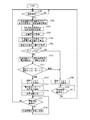
- FIG. 7 is a flowchart showing storage battery output control processing by the power storage device 300 of FIG.
- the device-to-device communication unit 307 performs authentication while searching for the portable terminal 100 for which pairing has been set via the antenna 301, and attempts wireless connection (step S301). When the wireless connection with the portable terminal 100 is not established (S301: NO), the process of step S301 is repeated.
- control unit 306 When wireless connection is established (S301: YES), the control unit 306 receives a signal of an output power control command (intermittent driving power output command) from the portable terminal 100 via the antenna 301 and the inter-device communication unit 307. It is determined whether or not (step S302).
- step S303 determines whether or not the power storage device 300 and the mobile terminal 100 are continuing wireless connection. If it is determined that the wireless connection is continuing (S303: YES), the process of step S302 is performed. On the other hand, when it is determined that the wireless connection is not being continued (S303: NO), the process of step S301 is performed.
- the control unit 306 controls the output control unit 310 to intermittently drive power from the storage battery 304 to the motor 512 of the electrically assisted bicycle 500. Is output (step S304).
- the electrically assisted bicycle 500 performs discontinuous operation by intermittently supplying driving power to the motor 512.
- the control unit 306 determines whether or not the power storage device 300 and the mobile terminal 100 are continuing wireless connection (step S305).
- control unit 306 When it is determined that the wireless connection is being continued (S305: YES), the control unit 306 outputs an output power control stop command (intermittent driving power output stop command) signal to the antenna 301 and the inter-device communication unit 307. Whether or not the mobile terminal 100 has been received is determined (step S306).
- step S304 If it is determined that the output power control stop command signal has not been received (S306: NO), the process of step S304 is performed.
- the control unit 306 controls the output control unit 310 to intermittently drive from the storage battery 304 to the motor 512 of the electrically assisted bicycle 500.
- the output of power is stopped (step S307).
- driving power is not intermittently supplied to the motor 512, and discontinuous operation is not performed.
- the control unit 306 controls the output control unit 310 to intermittently output drive power from the storage battery 304 to the motor 512 of the electric assist bicycle 500. Is stopped (step S308).
- driving power is not intermittently supplied to the motor 512, and discontinuous operation is not performed.
- the power storage device 300 cannot receive an intermittent stop command of driving power output from the mobile terminal 100 by wireless communication. For this reason, the power storage device 300 stops the output of the intermittent driving power without receiving a command from the mobile terminal 100 when the wireless connection is disconnected during the intermittent power output.
- FIG. 8 is a sequence diagram illustrating an example of a cooperative operation by the mobile terminal 100, the power storage device 300, and the electrically assisted bicycle 500 according to the first embodiment.
- FIG. 8 is a sequence diagram in the case where the user starts driving the electric power assisted bicycle outside the specific area, enters the specific area, and then exits the specific area.
- step S11 When the user carrying the mobile terminal 100 travels on the electric assist bicycle 500, the mobile terminal 100 and the power storage device 300 that have been previously set for pairing are wirelessly connected by approaching each other (step S11).
- the mobile terminal 100 acquires map information including specific area information from the server device in the cloud (step S12).
- the portable terminal 100 acquires position information of the portable terminal 100 using GPS (step S13). Then, the mobile terminal 100 determines whether the user is driving the power-assisted bicycle 500 within the specific area based on the specific area information and the position information, and determines that the user is driving outside the specific area. (Step S14).
- the portable terminal 100 acquires position information of the portable terminal 100 using GPS (step S15). And the portable terminal 100 determines whether the user is driving the electric assist bicycle 500 in the specific area based on the specific area information and the position information, and determines that the user is driving in the specific area. (Step S16).
- the portable terminal 100 transmits an output power control command (intermittent driving power output command) signal to the power storage device 300 (step S17).
- This command is an example of a command for reducing the driving power according to the present disclosure.
- the power storage device 300 receives the output power control command signal, and intermittently outputs drive power from the storage battery 304 to the motor 512 of the electrically assisted bicycle 500 based on the received output power control command (step S18). Thereby, the electrically assisted bicycle 500 performs a discontinuous operation (step S19).
- the transmission of the output power control command signal from the portable terminal 100 to the power storage device 300 is performed once in one run in the specific area.
- an output power control command signal may be transmitted each time it is determined to be within a specific area.
- the output power control stop command signal may not be transmitted from the portable terminal 100 to the power storage device 300.
- the power storage device 300 may stop intermittently outputting the driving power to the motor 512 of the electric assist bicycle 500 when the output power control command signal is not received for a predetermined period.
- the portable terminal 100 acquires position information of the portable terminal 100 using GPS (step S20). And the portable terminal 100 determines whether the user went out of the specific area from the specific area while driving the electric assist bicycle 500 based on the specific area information and the position information. Determination is made (step S21).
- the portable terminal 100 transmits an output power control stop command (intermittent driving power output stop command) signal to the power storage device 300 (step S22).
- the power storage device 300 receives the output power control stop command signal, and stops intermittently outputting drive power from the storage battery 304 to the motor 512 of the electric assist bicycle 500 based on the received output power control stop command. (Step S23). Thereby, the electrically assisted bicycle 500 does not perform discontinuous operation (step S24).
- the electrically assisted bicycle 500 when the user drives the electrically assisted bicycle 500 within a specific area, the electrically assisted bicycle 500 performs a discontinuous operation.
- This discontinuous operation allows the user to know that he / she is driving in a specific area.
- the user can drive the power-assisted bicycle 500 with great care in a specific area, and can prevent a collision with a moving body or a person such as an automobile or a bicycle. .
- the portable terminal 100 acquires the map information containing specific area information from the server apparatus in a cloud, and acquires repeatedly the positional information on the portable terminal 100 using GPS. Then, the mobile terminal 100 determines whether or not the user is driving the electric assist bicycle 500 in the specific area from the specific area information and the position information. When it is determined that the mobile terminal 100 is operating in a specific area, the mobile terminal 100 transmits an output power control command signal to the power storage device 300.
- the power storage device 300 receives the output power control command signal and intermittently outputs drive power from the storage battery 304 to the motor 512 of the electrically assisted bicycle 500.
- the mobile terminal 100 acquires map information including the specific area information from the server device in the cloud and transmits it to the power storage device 300.
- the mobile terminal 100 repeatedly acquires position information of the mobile terminal 100 using GPS and transmits the position information to the power storage device 300.
- the power storage device 300 determines whether the user is driving the power-assisted bicycle 500 in the specific area from the specific area information and the position information. And when it determines with the electrical storage apparatus 300 driving
- the portable terminal 100, the power storage device 300, and the electrically assisted bicycle 500 can use substantially the same configurations as those shown in FIGS.
- the control unit 106 of the mobile terminal 100 executes a storage battery output control process described later with reference to FIG. 9 in cooperation with other units of the mobile terminal 100.
- control unit 106 transmits map information including the specific area information received from the server device in the cloud to the power storage device 300. In addition, control unit 106 transmits position information repeatedly acquired by GPS unit 109 to power storage device 300.
- the control unit 306 of the power storage device 300 executes a storage battery output control process, which will be described later with reference to FIG.
- the control unit 306 determines whether the mobile terminal 100 is in the specific area, that is, the user Determines whether or not the motor-assisted bicycle 500 is driven in a specific area. Then, when the control unit 306 determines that the user is driving the electric assist bicycle 500 within the specific area, the control unit 306 controls the output control unit 310 to intermittently transfer the electric battery from the storage battery 304 to the motor 512 of the electric assist bicycle 500. Outputs driving power.
- the control unit 306 converts the specific area information and the position information received repeatedly. Based on this, it is determined whether or not the mobile terminal 100 is outside the specific area, that is, whether or not the mobile terminal 100 is out of the specific area from the specific area during the driving of the electric assist bicycle 500.
- the control unit 306 determines that the electric assist bicycle 500 is out of the specific area while driving the electric assist bicycle 500, the control unit 306 controls the output control unit 310 to intermittently connect the battery 512 to the motor 512 of the electric assist bicycle 500. The output of the driving power is stopped.
- FIG. 9 is a flowchart showing a storage battery output control process by the mobile terminal 100 in the second embodiment.
- the inter-device communication unit 108 attempts to establish a wireless connection by performing authentication while searching for the power storage device 300 for which pairing is set via the antenna 102 (step S151).
- the wireless connection with power storage device 300 is not established (S151: NO)
- the process of step S151 is repeated.
- wireless connection is established (S151: YES)
- the control unit 106 acquires map information including specific area information from the server device in the cloud via the antenna 101 and the network communication unit 107 (step S152). Then, control unit 106 transmits map information including specific area information to power storage device 300 via inter-device communication unit 108 and antenna 102 (step S153).
- the GPS unit 109 acquires position information of the mobile terminal 100 (step S154). Then, the control unit 106 transmits the position information of the portable terminal 100 to the power storage device 300 via the inter-device communication unit 108 and the antenna 102 (step S155).
- the control unit 106 determines whether the mobile terminal 100 and the power storage device 300 are continuing wireless connection (step 156). When it is determined that the wireless connection is continuing (S156: YES), the process of step S154 is performed. On the other hand, when it is determined that the wireless connection is not ongoing, that is, the wireless connection is disconnected (S156: NO), the process of step S151 is performed.
- FIG. 10 is a flowchart showing a storage battery output control process by the power storage device 300 according to the second embodiment.
- the device-to-device communication unit 307 performs authentication while searching for the portable terminal 100 for which pairing has been set via the antenna 301, and attempts wireless connection (step S351). If the mobile terminal 100 is not wirelessly connected (S351: NO), the process of step S351 is repeated.
- control unit 306 receives map information including specific area information from the mobile terminal 100 via the antenna 301 and the inter-device communication unit 307 (step S352).
- the control unit 306 receives the position information of the mobile terminal 100 from the mobile terminal 100 via the antenna 301 and the inter-device communication unit 307 (step S353). Based on the specific area information and the position information, the control unit 306 determines whether or not the mobile terminal 100 is in the specific area, that is, whether or not the user is driving the power-assisted bicycle 500 in the specific area. (Step S354).
- Step S355 determines whether or not the mobile terminal 100 and the power storage device 300 are continuing wireless connection. If it is determined that the wireless connection is continuing (S355: YES), the process of step S353 is performed. On the other hand, when it is determined that the wireless connection is not being continued (S355: NO), the process of step S351 is performed.
- the control unit 306 controls the output control unit 310 to change the battery 512 to the motor 512 of the power-assisted bicycle 500.
- Driving power is intermittently output (step S356).
- the electrically assisted bicycle 500 performs a discontinuous operation when intermittent driving power is supplied to the motor 512. By the discontinuous operation of the electric assist bicycle 500, the user can recognize that he / she is riding the electric assist bicycle 500 in a specific area.
- the control unit 306 determines whether or not the mobile terminal 100 and the power storage device 300 are continuing the wireless connection (step S357).
- the control unit 306 receives the position information of the mobile terminal 100 from the mobile terminal 100 via the antenna 301 and the inter-device communication unit 307 (step S358). Based on the specific area information and the position information, the control unit 306 determines whether or not the mobile terminal 100 is outside the specific area, that is, whether or not the mobile terminal 100 is out of the specific area from the specific area while driving the electric assist bicycle 500. Is determined (step S359).
- step S356 When it is determined that the user has not gone out of the specific area from the specific area while driving the electric assist bicycle 500 (S359: NO), the process of step S356 is performed.
- the control unit 306 controls the output control unit 310 to control the electric assist bicycle 500 from the storage battery 304.
- the drive power is intermittently output to the motor 512 (step S360). In the electrically assisted bicycle 500, intermittent driving power is not supplied to the motor 512, and discontinuous operation is not performed.
- step S361 When it is determined that the wireless connection is not being continued (S357: NO), the control unit 306 controls the output control unit 310 to intermittently output driving power from the storage battery 304 to the motor 512 of the electrically assisted bicycle 500. To stop (step S361).
- the electrically assisted bicycle 500 intermittent driving power is not supplied to the motor 512, and discontinuous operation is not performed.
- the wireless connection is disconnected in the specific area, for example, the electric assist bicycle 500 is in the specific area, but when the user leaves the electric assist bicycle 500, the discontinuous operation with the electric assist bicycle 500 is performed. There is no need to make it happen. For this reason, the process of step S361 is performed.
- FIG. 11 is a sequence diagram illustrating an example of a cooperative operation by the mobile terminal 100, the power storage device 300, and the electrically assisted bicycle 500 according to the second embodiment.
- FIG. 11 is a sequence diagram in the case where the user starts driving the electric power assisted bicycle outside the specific area, enters the specific area, and then exits the specific area.
- step S51 When the user carrying the mobile terminal 100 travels on the electrically assisted bicycle 500, the mobile terminal 100 and the power storage device 300 that have been previously set for pairing are wirelessly connected by approaching each other (step S51).
- the mobile terminal 100 acquires map information including the specific area information from the server device in the cloud (step S52), and transmits the map information including the acquired specific area information to the power storage device 300 (step S53).
- step S55 is a step of acquiring information related to the position of the electric vehicle from the portable terminal.
- step S56 is a step of determining whether or not the electric vehicle is in a specific area from information regarding the position of the electric vehicle.
- step S58 is a step of acquiring information related to the position of the electric vehicle from the portable terminal.
- the power storage device 300 determines whether the user is driving the electric assist bicycle 500 in the specific area based on the specific area information and the position information, and determines that the user is driving in the specific area (step). S59).
- step S59 is a step of determining whether or not the electric vehicle is in a specific area from information on the position of the electric vehicle.
- the power storage device 300 intermittently outputs drive power from the storage battery 304 to the motor 512 of the electrically assisted bicycle 500 (step S60). Thereby, the electrically assisted bicycle 500 performs a discontinuous operation (step S61).
- step S62 acquires position information using GPS (step S62), and transmits the acquired position information to the power storage device 300 (step S63).
- step S63 is a step of acquiring information related to the position of the electric vehicle from the portable terminal.
- step S64 is a step of determining whether or not the electric vehicle is in a specific area from information regarding the position of the electric vehicle.
- the power storage device 300 stops outputting drive power intermittently from the storage battery 304 to the motor 512 of the electrically assisted bicycle 500 (step S65). Thereby, the electrically assisted bicycle 500 does not perform discontinuous operation (step S66).
- the electrically assisted bicycle 500 when the user drives the electrically assisted bicycle 500 within the restricted area, the electrically assisted bicycle 500 performs a discontinuous operation.
- This discontinuous operation allows the user to know that he / she is driving in a specific area.
- the user can drive the power-assisted bicycle 500 with great care in a specific area, and can prevent a collision with a moving body or a person such as an automobile or a bicycle. .
- the third embodiment is not intended to let the user know that he / she is driving a power-assisted bicycle in a specific area as in the first and second embodiments. It is based on such issues and purposes.
- the first uphill may be gentle and the last uphill may be steep.
- the amount of power remaining in the storage battery (hereinafter referred to as “remaining power amount”).
- the remaining power of the storage battery is used for driving the motor on the first gentle uphill.
- the user may not be able to receive motor-driven electric assistance on the last steep uphill.
- the above-described normal method cannot receive the above-described electric assistance that is considered appropriate for the user depending on the remaining power amount of the storage battery.
- the third embodiment is intended to allow the user to receive electric assistance by driving an appropriate motor for the user until the user arrives at the destination.
- One electric assist mode is a mode for controlling the driving power supplied from the storage battery to the motor based on the pedaling force etc. in the pedal without considering the process to the destination and the remaining power amount of the storage battery. This is referred to as “normal assist mode”. Since the normal assist mode is a mode that is generally performed, detailed description thereof is omitted in the third embodiment.
- the other motor-assisted mode is a mode for controlling the driving power supplied from the storage battery to the motor in consideration of the process to the destination and the remaining power amount of the storage battery, and is hereinafter referred to as “adjustment assist mode”.
- the portable terminal 100, the power storage device 300, and the electrically assisted bicycle 500 can use substantially the same configurations as those shown in FIGS.
- control unit 106 of the mobile terminal 100 performs power distribution processing described later with reference to FIG. 17 in cooperation with other units of the mobile terminal 100.
- the control unit 106 calculates a power amount P1 of the storage battery 304 estimated to be used from the departure place to the destination (hereinafter referred to as “necessary power estimated amount”) P1.
- the departure point is the position of the mobile terminal 100 acquired by the GPS unit 109 when the paired mobile terminal 100 and the power storage device 300 are wirelessly connected.
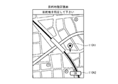
- the destination is a point designated by the user using a destination designation screen shown in FIG.
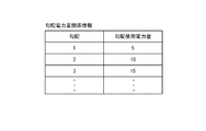
- the control unit 106 transmits (1) map information including gradient information from the server device in the cloud, and (2) the gradient illustrated in FIG. 14 and the power amount of the storage battery 304 assumed to be used with the gradient (hereinafter, “ Gradient power amount relationship information indicating a relationship with “gradient power consumption” is acquired.
- the gradient information includes information indicating the gradient from one point to the other point between each two points.
- the gradient power consumption is a power consumption per unit distance with respect to the gradient, and is set in advance such that the gradient use power amount increases as the slope rises steeply.
- the control unit 106 determines the journey from the departure point to the destination based on the map information. Then, the control unit 106 divides the journey from the departure point to the destination between a plurality of two points, and considers the journey from the departure point to the destination based on the gradient information, and the gradient between the two points in the traveling direction. Is identified. When the traveling direction is from one point to the other point, the gradient indicated in the gradient information is used as it is, and when the traveling direction is from the other point to the one point, it is indicated in the gradient information. Use the opposite slope to
- the control unit 106 refers to the gradient power amount relation information and sets the gradient power consumption (A) corresponding to the gradient between the two points in the traveling direction between the two points from the departure point to the destination. And the sum of the multiplication results (A ⁇ B) is calculated. This total value is the required power estimation amount P1.
- the above is an example of a method for calculating the required power estimation amount P1.
- the control unit 106 receives storage battery information including the remaining power amount P2 of the storage battery 304 from the power storage device 300.
- the control unit 106 receives, for example, storage battery information including an index indicating the remaining power amount P2 of the storage battery 304 from the power storage device 300, and from the received index.
- the remaining power amount P2 of the storage battery 304 may be specified.
- the control unit 106 determines whether or not the remaining power amount P2 of the storage battery 304 is greater than the required power estimation amount P1 by a threshold Pth or more (P2 ⁇ P1 ⁇ Pth?).
- the control unit 106 can receive a large amount of electric assistance as the uphill is steep.
- the amount of electric power hereinafter referred to as “distributed electric energy”
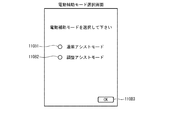
- the adjustment assist mode is designated by the user using a power assist mode screen shown in FIG.
- the control unit 106 stores power distribution pattern information including position information indicating the first point, position information indicating the second point, and information on the amount of electric power distributed from the first point to the second point between the two points. To device 300.
- the control unit 106 obtains the amount of electric power (C) distributed between the two points from the departure point to the destination as follows.
- the control unit 106 multiplies the gradient power consumption (A) corresponding to the gradient between the two points in the traveling direction by the distance (B) between the two points, and uses the multiplication result (A ⁇ B) as the required power estimation amount. Divide by P1. Then, the control unit 106 multiplies the remaining power amount P2 of the storage battery 304 by the division result ((A ⁇ B) / P1).
- the multiplication result (P2 ⁇ (A ⁇ B) / P1) is the distribution power amount (C) between the two points.
- the determination of the amount of electric power distributed between the two points is not limited to the above, and may be as follows, for example.
- a weighting calculation is performed so that the weight between the two points on the steep uphill is larger so that the larger electric assistance can be received as the uphill is steep.
- the amount of power may be determined.
- the control unit 106 obtains the multiplication result (A ⁇ B) of the gradient power consumption (A) corresponding to the gradient between the two points in the traveling direction and the distance (B) between the two points. It adds in order from two points where the uphill of the traveling direction is steep. And the control part 106 is each 2 points
- the power distribution amount (C) between the two is determined as a multiplication result (A ⁇ B) of the gradient power consumption amount (A) corresponding to the gradient between the two points in the traveling direction and the distance (B) between the two points. .
- the control unit 106 distributes the remaining power amount (P2 ⁇ (100 ⁇ A) / 100) of the remaining power amount P2 of the storage battery 304 between the other two points.
- the distribution electric energy between each other two points is determined by performing weighting calculation, for example.
- the display unit 110 of the portable terminal 100 is controlled by the control unit 106, and displays a destination designation screen shown as an example in FIG.
- the user operates the operation unit 111 to move the pin 110A1 to the destination, moves the pin 110A1 to the destination, and then clicks an “OK” button 110A2. In this way, the user can specify the destination.
- the map in the destination designation screen can be enlarged or the display range can be changed.
- the display unit 110 is controlled by the control unit 106 and displays an electric assist mode selection screen shown in FIG. 16 as an example.
- the user operates the operation unit 111 to check one of the radio buttons 110B1 and 110B2, and after checking it, clicks an “OK” button 110B3. In this way, the user can select one of the normal assist mode and the adjustment assist mode.
- control unit 306 of the power storage device 300 performs power distribution processing described later with reference to FIG. 18 in cooperation with other units of the power storage device 300.
- the control unit 306 receives the power assist mode information indicating the adjustment assist mode from the mobile terminal 100, and further receives the power distribution pattern information. And the control part 306 acquires repeatedly the positional information on the portable terminal 100 based on GPS from the portable terminal 100.
- the control unit 306 specifies between which two points from the departure point to the destination the user is traveling, based on the first and second points of the power distribution pattern information and the position information acquired from the mobile terminal 100. . And the control part 306 specifies the distribution electric energy between the specified 2 points
- the control unit 306 controls the output control unit 310 according to the specified distributed power amount between the two points specified that the user is traveling, and outputs drive power from the storage battery 304 to the motor 512 of the electric assist bicycle 500. To do.
- the control unit 306 estimates the speed at which the user is traveling from position information based on GPS repeatedly acquired from the mobile terminal 100, and estimates the time required for movement between the two points from the distance between the two points and the traveling speed. . Then, the control unit 306 outputs the power of the distributed power amount from the storage battery 304 to the motor 512 over the travel time.
- time required for movement between two points may be determined in advance.
- FIG. 17 is a flowchart showing power distribution processing by the mobile terminal 100 according to the third embodiment.
- the inter-device communication unit 108 attempts to establish a wireless connection by performing authentication while searching for the power storage device 300 for which pairing is set via the antenna 102 (step S701).
- the wireless connection with power storage device 300 is not established (S701: NO)
- the process of step S701 is repeated.
- the control unit 106 transmits the map information including the gradient information and the gradient power illustrated in FIG. 14 from the server device in the cloud via the antenna 101 and the network communication unit 107. Quantity-related information is acquired (step S702).
- the control unit 106 displays the destination designation screen shown as an example in FIG.
- the user operates the operation unit 111 to specify a destination, and the control unit 106 receives destination information indicating the destination from the operation unit 111 (step S703).
- the GPS unit 109 acquires position information of the mobile terminal 100 using GPS (step S704). However, the position information acquired in step S704 indicates the departure place.
- the control unit 106 calculates the required power estimation amount P1 from the departure place to the destination as described above (step S705).
- the control unit 106 inquires of the power storage device 300 about the remaining power amount P2 of the storage battery 304 via the inter-device communication unit 108 and the antenna 102. And as a response, the control part 106 receives the remaining electric energy information which shows the remaining electric energy P2 of the storage battery 304 from the electrical storage apparatus 300 via the antenna 102 and the inter-apparatus communication part 108 (step S706).
- the control unit 106 determines whether or not the remaining power amount P2 of the storage battery 304 is greater than the required power estimation amount P1 by a threshold Pth or more (P2 ⁇ P1 ⁇ Pth?) (Step S707).
- the control unit 106 transmits the electric assist mode information indicating the normal assist mode to the inter-device communication unit 108 and the antenna 102. To the power storage device 300 (step S708).
- the control unit 106 determines whether or not the mobile terminal 100 and the power storage device 300 are continuing wireless connection (step S709). When it is determined that the wireless connection is continuing (S709: YES), the process of step S709 is repeated. On the other hand, when it is determined that the wireless connection is not continuing (S709: NO), the process of step S701 is performed.
- the control unit 106 displays a power assist mode selection screen as an example shown in FIG.
- the user operates the operation unit 111 to select the normal assist mode or the adjustment assist mode, and the control unit 106 receives the power assist mode information indicating the power assist mode selected by the user from the operation unit 111 (step S710).
- the control unit 106 determines which one of the normal assist mode and the adjustment assist mode the user has selected based on the electric assist mode information (step S711).
- step S708 If it is determined that the user has selected the normal assist mode (S711: normal), the process of step S708 is performed.
- the control unit 106 transmits the power assist mode information indicating the adjustment assist mode to the power storage device 300 via the inter-device communication unit 108 and the antenna 102. (Step S712).
- control unit 106 determines the amount of power distributed between each two points from the departure point to the destination, and based on the determination result, transmits power distribution pattern information via the inter-device communication unit 108 and the antenna 102. To the power storage device 300 (step S713).
- the control unit 106 transmits the position information of the departure place acquired in step S704 to the power storage device 300 via the inter-device communication unit 108 and the antenna 102 (step S714).
- the control unit 106 determines whether or not the mobile terminal 100 and the power storage device 300 are continuing wireless connection (step S715).
- the GPS unit 109 acquires the position information of the mobile terminal 100 using the GPS, and the control unit 106 obtains the position information from the inter-device communication unit 108 and Transmission is performed to the power storage device 300 via the antenna 102 (step S716).
- the process of step S701 is performed.
- FIG. 18 is a flowchart showing power distribution determination processing by the power storage device 300 according to the third embodiment.
- the inter-device communication unit 307 attempts to establish a wireless connection by performing authentication while searching for the mobile terminal 100 for which pairing has been set via the antenna 301 (step S751). If the mobile terminal 100 is not wirelessly connected (S751: NO), the process of step S751 is repeated.
- the control unit 306 When wireless connection is established (S751: YES), the control unit 306 receives an inquiry about the remaining power amount P2 of the storage battery 304 from the mobile terminal 100 via the antenna 301 and the inter-device communication unit 307, and the remaining power amount of the storage battery 304. P2 is detected. Then, as a response to the inquiry, the control unit 306 transmits remaining power amount information indicating the remaining power amount P2 of the storage battery 304 to the mobile terminal 100 via the inter-device communication unit 307 and the antenna 301 (step S752).
- the control unit 306 receives the power assist mode information from the mobile terminal 100 via the antenna 301 and the inter-device communication unit 307 (step S753). Then, the control unit 306 determines whether to operate in the normal assist mode or the adjustment assist mode based on the electric assist mode information (step S754).
- the electric assist mode of the power storage device 300 When it is determined to operate in the normal assist mode (S754: normal), the electric assist mode of the power storage device 300 is in the normal assist mode, and the control unit 306 controls the output control unit 310 to control the motor of the electric assist bicycle 500 from the storage battery 304.
- the driving power is output to 512 (step S755).
- the control unit 306 determines whether or not the power storage device 300 and the mobile terminal 100 are continuing wireless connection (step S756). When it is determined that the wireless connection is continuing (S756: YES), the process of step S755 is performed. On the other hand, if it is determined that the wireless connection is not continuing (S756: NO), the process of step S751 is performed.
- the electric assist mode of the power storage device 300 is set to the adjustment assist mode (step S757).
- the control unit 306 receives power distribution pattern information from the mobile terminal 100 via the antenna 301 and the inter-device communication unit 307 (step S758).
- the control unit 306 acquires position information from the mobile terminal 100 via the antenna 301 and the inter-device communication unit 307 (step S759).
- the control unit 306 controls the output control unit 310 and, as described above, based on the power distribution pattern information and the position information, the power for driving the distributed power amount from the storage battery 304 to the motor 512 of the electrically assisted bicycle 500. Output (step S760).
- the control unit 306 determines whether or not the power storage device 300 and the mobile terminal 100 are continuing wireless connection (step S761). When it is determined that the wireless connection is being continued (S761: YES), the control unit 306 receives position information from the mobile terminal 100 via the antenna 301 and the inter-device communication unit 307 (step S762). On the other hand, when it is determined that the wireless connection is not continuing (S761: NO), the process of step S751 is performed.
- the present disclosure is not limited to the contents described in the above embodiment, and can be implemented in any form for achieving the purpose of the present disclosure and related or incidental purposes. .
- the battery-assisted battery 500 of the power storage device 300 is operated so that the power-assisted bicycle 500 performs a discontinuous operation.
- the output of drive power to the motor 512 is controlled.
- the power output may be controlled.
- the output power control command is a command for suppressing the driving power output from the storage battery 304 to the motor 512.
- the output suppression of the driving power is an example in which the driving power is reduced when the electric vehicle according to the present disclosure is in the specific area than when the electric vehicle is outside the specific area.
- the waveform of the driving power output from the storage battery 304 to the motor 512 is set as a pulse waveform, and the magnitude of the driving power output from the storage battery 304 to the motor 512 is controlled by the pulse width.
- it can be implemented by reducing the pulse width so that the driving power output from the storage battery 304 to the motor 512 is smaller than the driving power required by the pedaling force detected by the pedaling force detection unit 507.
- the duty ratio is reduced.
- the output suppression of the driving power is realized by using, for example, a switching element that turns on / off the supply of driving power from the power storage device to the electric vehicle, but is not limited thereto.
- An FET is exemplified as the switching element.
- the output power of the storage battery 304 is controlled.
- the present invention is not limited to this.
- the output control may be performed.
- Such a case is also an example of driving power control when the electric vehicle is in a specific area.
- the following (3-A) may be performed, and when applied to the second embodiment, the following (3-B) is performed. ).
- a portable terminal (hereinafter referred to as “user portable terminal”) 100 possessed by a user riding on the electric assist bicycle 500 is transferred from a server device in the cloud to other portable terminals 1000A and 1000B other than the user portable terminal 100. ,... Are repeatedly acquired.
- the user portable terminal 100 is connected to the other portable terminals 1000A, 1000B, 1000B within a predetermined distance from the position information of the user portable terminal 100 and the position information of the other portable terminals 1000A, 1000B,. It is determined whether or not there are more than a predetermined number.
- the user portable terminal 100 determines that there are more than a predetermined number of other portable terminals within a predetermined distance, the user portable terminal 100 wirelessly communicates a signal of an output power control command (intermittent driving power output command) to the power storage device 300. Send in.
- the presence of a predetermined number or more of the other mobile terminals 1000A, 1000B,... Within a predetermined distance from the user mobile terminal 100 is an example of the presence of the electric mobile body in the specific area.
- the power storage device 300 receives an output power control command signal, and intermittently outputs drive power from the storage battery 304 to the motor 512 of the electric assist bicycle 500 based on the output power control command.
- the user portable terminal 100 After transmitting the output power control command signal, the user portable terminal 100 determines a predetermined value for the user portable terminal 100 from the position information of the user portable terminal 100 and the position information of the other portable terminals 1000A, 1000B,. It is determined whether there are more than a predetermined number of other mobile terminals 1000A, 1000B,... Within the distance. When the user portable terminal 100 determines that there are no more than a predetermined number of other portable terminals within a predetermined distance, the user portable terminal 100 outputs a signal of an output power control stop command (intermittent driving power output stop command) It transmits to 300 by radio
- an output power control stop command intermittent driving power output stop command
- the power storage device 300 receives the output power control stop command signal and stops intermittently outputting drive power from the storage battery 304 to the motor 512 of the electric assist bicycle 500 based on the output power control stop command.
- the user portable terminal 100 repeatedly obtains the position information of the portable terminals 1000A, 1000B,... Other than the user portable terminal 100 from the server device in the cloud and transmits the position information to the power storage device 300 by wireless communication.
- the power storage device 300 includes other mobile terminals 1000A, 1000B,... Within a predetermined distance from the user mobile terminal 100 based on the position information of the user mobile terminal 100 and the position information of the other mobile terminals 1000A, 1000B,. .. Determine whether there are more than a predetermined number.
- the power storage device 300 intermittently outputs driving power from the storage battery 304 to the motor 512 of the electrically assisted bicycle 500 when it is determined that a predetermined number or more of other mobile terminals exist within a predetermined distance.
- the power storage device 300 After starting to output the driving power intermittently, the power storage device 300 uses the position information of the user portable terminal 100 and the position information of the other portable terminals 1000A, 1000B,. It is determined whether or not there are more than a predetermined number of other portable terminals 1000A, 1000B,... Within a predetermined distance. The power storage device 300 stops intermittently outputting drive power from the storage battery 304 to the motor 512 of the electrically assisted bicycle 500 when it is determined that there are no more than a predetermined number of other mobile terminals within a predetermined distance. .
- the output power control condition may be within a specific area and proceeding in the direction of an intersection. Also, it may be within a specific area and traveling downhill.
- the map information it is possible to determine whether or not the electrically assisted bicycle 500 is traveling in the direction of the intersection by using position information based on GPS that is repeatedly acquired. Whether the power-assisted bicycle 500 is going downhill by using the height information of each point in the map information and using the position information based on the GPS information repeatedly acquired and the height information of each point. Can be determined.
- the mobile terminal 100 has been described as acquiring position information using GPS and transmitting it to the power storage device 300.
- the present invention is not limited to this. 300 may acquire position information using GPS.
- the device to be controlled is the storage battery 304 or the motor 512
- the control content is intermittent output of drive power from the storage battery 304 to the motor 512 or the motor 512.
- the present invention is not limited to this. For example, the following may be used.
- the device to be controlled is a display unit 600 having a display device attached in the vicinity of the handle of the electrically assisted bicycle 500 shown in FIG. 20 as an example, and the control content reaches the destination on the display unit of the display device. Therefore, the direction 610, 620, 630 to be traveled is displayed.
- the display unit 600 has a function of performing wireless communication with the mobile terminal 100. Further, the direction indicated by the black arrow is the direction to be reached in order to reach the destination.
- the mobile terminal 100 receives map information from a server device in the cloud.
- the mobile terminal 100 displays a destination designation screen on the display unit 110 and acquires destination information indicating the destination from the operation unit 111. Furthermore, the mobile terminal 100 acquires position information (information indicating a departure place) of the mobile terminal 100 using GPS. The mobile terminal 100 uses these pieces of information to determine the journey from the departure place to the destination.
- the mobile terminal 100 repeatedly acquires position information using GPS, specifies the direction in which the user should travel using the position information and the determined process, and displays direction information indicating the direction to travel by wireless communication on the display unit 600. Send to.
- the display unit 610 displays the direction to be advanced to the display unit based on the direction information received from the mobile terminal 100.
- the mobile terminal 100 further acquires accident information or traffic jam information from the server device in the cloud, and determines the journey from the departure point to the destination using the accident information or traffic jam information in addition to the map information. Also good.
- the mobile terminal 100 may acquire the weather forecast information from the server device in the cloud, and may determine the journey from the departure place to the destination by adding the weather forecast information.
- a map may be displayed on the display unit of the display unit to guide the user from the departure place to the destination.
- the power distribution process is performed using the gradient information and the gradient power amount relation information included in the map information acquired from the server device in the cloud.
- the present invention is not limited to this. For example, the following may be used.
- the power storage device 300 repeatedly acquires the position information from the mobile terminal 100 and repeatedly acquires the remaining power amount of the storage battery while traveling in the normal assist mode.
- the power storage device 300 uses the two pieces of position information acquired continuously from the mobile terminal 100 and the remaining battery power amount acquired in each of the two pieces of position information, and the storage battery power usage history information shown in FIG. 21 as an example. Update. In addition, when there is no remaining power amount of a storage battery, since the power is not supplied from the storage battery 304 to the motor 512, the storage battery power usage history information is not updated.
- This storage battery power usage history information is updated as follows.
- Add location information of the first point and the second point to the storage battery power usage history information are set as the average power consumption between points.
- the time (movement time) from the reception of the position information indicating one point to the reception of the position information indicating the second point is defined as the average movement time, and the value “1” is added to the storage battery power usage history information as the number of times.
- a value obtained by subtracting the remaining power amount of the storage battery 304 at the second point from the remaining power amount of the storage battery 304 at the first point (power consumption between points) (a) is calculated.
- the value (a + (b ⁇ c)) obtained by adding the inter-point power consumption (a) and the multiplication result (b ⁇ c) is divided by the value (c + 1) obtained by adding the value “1” to the number of times (c).
- the value ((a + (b ⁇ c)) / (c + 1)) is calculated.
- the time (d) between the reception of the position information indicating the first point and the reception of the position information indicating the second point (d) is obtained.
- the value (e ⁇ c) obtained by multiplying the average travel time (e) and the number of times (c) of the storage battery power usage history information corresponding to the first point and the second point is calculated.
- the average travel time (e) of the storage battery power usage history information corresponding to the first point and the second point is replaced with the division result ((d + (e ⁇ c)) / (c + 1)).
- the above is an example of a method for obtaining the usage status of the storage battery power.
- the mobile terminal 100 determines the journey from the departure point to the destination based on the map information.
- the mobile terminal 100 acquires storage battery power usage history information from the power storage device 300.
- the mobile terminal 100 refers to the storage battery power usage history information, and calculates the total of the inter-point average power consumption between each two points from the departure point to the destination. This total value is the required power estimation amount P1.
- the mobile terminal 100 When it is determined that the remaining power amount P2 of the storage battery 304 is not greater than the threshold value Pth than the required power estimation amount P1 and the user selects the adjustment assist mode, the mobile terminal 100 performs the following.
- the mobile terminal 100 refers to the storage battery power usage history information, divides the point-to-point average power consumption (E) between the two points by the required power estimation amount P1, and divides it into the remaining power amount P2 of the storage battery 304 (E / Multiply P1).
- This multiplication result (P2 ⁇ (E / P1)) is the power distribution amount between the two points. This calculation is performed between each two points from the departure point to the destination.
- the determination of the amount of electric power distributed between the two points is not limited to the above, and for example, the weighting calculation as described in the modification (1) of the third embodiment is performed to perform each weighting calculation. You may make it determine the distribution electric energy between two points. Moreover, between two points with a steep uphill as described in the modified example (2), the average power consumption between points may be determined as the allocated power amount as it is.
- the mobile terminal 100 includes position information indicating the first point, position information indicating the second point, information on the amount of electric power distributed from the first point to the second point, and the first point to the second point between the two points.
- Power distribution pattern information including information on the average travel time is transmitted to power storage device 300.
- the power storage device 300 receives the power distribution pattern information from the mobile terminal 100. Then, the power storage device 300 repeatedly acquires the position information of the mobile terminal 100 based on GPS from the mobile terminal 100.
- the mobile terminal 100 specifies between which two points from the departure point to the destination the user is traveling from the first and second points of the power distribution pattern information and the position information acquired from the mobile terminal 100. . And the portable terminal 100 specifies the amount of distribution electric power between the specified two points from the power distribution pattern information.
- the portable terminal 100 outputs the driving power of the allocated power amount from the storage battery 304 to the motor 512 of the electrically assisted bicycle 500 over the average travel time between the two points specified as the user is traveling.
- the remaining power amount of the storage battery 304 may be acquired from the power storage device 300 to create storage battery power usage history information.
- the designated section for determining the allocated power amount has been described as the section from the departure place to the destination designated by the user, but is not limited thereto. Absent.
- the designated section for determining the distributed power amount may be between two points designated by the user.
- the amount of electric power to be allocated once is determined at the time of departure.
- the present invention is not limited to this.
- the way from the departure point to the destination You may make it determine distribution electric energy again in the area from a position to the destination.
- the designated section is a section from a midway position to the destination.
- the mobile terminal 100 displays a message prompting charging on the display unit 110, An e-mail or the like destined for the portable terminal 100 may be transmitted.
- the power storage devices 300 and 300A store the storage battery information history information indicating the history of the charging place and the charging time zone in the memory 305.
- the power storage devices 300 and 300A update the storage battery charging history information stored in the memory 305 every time the storage battery 304 is charged. Then, the power storage device 300 transmits the updated storage battery charging history information to the mobile terminal 100, and the mobile terminal 100 receives the storage battery charging history information from the power storage device 300.
- the portable terminal 100 determines whether or not it is a charging place and a charging time zone based on the storage battery charging history information.
- the power storage device 300, 300A is inquired about the remaining power amount of the storage battery 304, and the remaining power amount is received from the power storage device 300, 300A as a response to the inquiry. get.
- the mobile terminal 100 displays a message prompting charging on the display unit 110 or transmits an e-mail addressed to itself (mobile terminal) 100 or the like. It may be.
- the mobile terminal 100 has been described as acquiring position information using GPS and transmitting it to the power storage device 300.
- the present invention is not limited to this. 300 may acquire position information using GPS.
- the mobile terminal 100 or the power storage device 300 determines whether or not the electric vehicle is in the specific area. Good.
- the server apparatus acquires the position information of the mobile terminal 100 from the mobile terminal 100, and performs the above determination.
- the server device may transmit the determination result to the mobile terminal 100, or may transmit a command related to output control of the driving power of the power storage device 300 based on the determination result to the mobile terminal 100. Note that the command transmitted to the mobile terminal 100 is transmitted to the power storage device 300.
- the mobile terminal 100 transmits the result to the power storage device 300, and the power storage device 300 outputs the driving power of the power storage device 300 based on the result. You may control. Alternatively, portable terminal 100 may transmit a command related to output control of power for driving power storage device 300 to power storage device 300 based on the transmitted determination result.
- GPS is used to acquire position information.
- the present invention is not limited to this, and any apparatus that can acquire position information can be used. It may be.
- An external factor that does not directly involve the electric vehicle to which the power storage device is attached is, for example, a specific area in each of the above-described embodiments.
- (3-A) and (3-B) above Although there are other mobile terminals near the terminal, it is not particularly limited to these.
- each component may be individually made into one chip, or may be made into one chip so as to include a part or all of them.
- LSI Large Scale Integration
- IC Integrated Circuit
- system LSI super LSI
- ultra LSI ultra LSI depending on the degree of integration.
- the method of circuit integration is not limited to LSI, and implementation with a dedicated circuit or a general-purpose processor is also possible.
- An FPGA Field Programmable Gate Array
- a reconfigurable processor capable of reconfiguring connection and setting of circuit cells inside the LSI may be used. Furthermore, if integrated circuit technology comes out to replace LSI's as a result of the advancement of semiconductor technology or a derivative other technology, it is naturally also possible to carry out function block integration using this technology.
- a method for controlling a power storage device is a method for controlling a power storage device mounted on an electric vehicle, wherein the electric vehicle is in a specific area than when it is outside a specific area.
- the power storage device of the present disclosure is a power storage device mounted on an electric vehicle, and includes a storage battery, an output control unit that controls output of driving power from the storage battery to the electric vehicle, and the electric vehicle includes: A control unit configured to control the output control unit when in a specific area and to reduce driving power supplied from the power storage device to the electric mobile body as compared to when outside the specific area.
- the program of the present disclosure is a program that is executed in a power storage device attached to an electric vehicle, and when the electric mobile body is in a specific area, the electric storage device is more likely to have the electric A process of reducing the driving power supplied to the moving body is executed.
- the driving power supplied from the power storage device to the electric vehicle is less than when the electric vehicle is outside the specific area.
- the output of the driving power may be limited so that the driving power is reduced as compared to when it is outside the specific area, or the driving power may be controlled to be intermittently reduced.
- the power storage device According to each of the power storage device control method, the power storage device, and the program, the power storage device according to the present disclosure is provided in the power storage device even if the function of controlling the driving force within the specific area is not previously installed in the electric vehicle itself. By executing the above control, it is possible to reduce the driving force of the electric vehicle within the specific area.
- step (A2) In the method for controlling a power storage device according to the present disclosure, in the step (a), the driving power is reduced using a switching element that turns on / off the supply of driving power from the power storage device to the electric vehicle. Decrease.
- the power storage device control method according to the present disclosure is the above-described power storage device control method according to (A1) or (A2).
- the drive device is supplied from the storage battery to the electric vehicle. Reduce power intermittently.
- the electric vehicle equipped with the power storage device it becomes possible to cause the electric vehicle equipped with the power storage device to perform discontinuous operation. For example, by causing the electric vehicle equipped with the power storage device to perform a discontinuous operation, the user can be alerted to the operation of the electric vehicle.
- a power storage device control method is the power storage device control method according to any one of (A1) to (A3) described above, wherein the driving power is applied to the electric vehicle in a pulsed waveform.
- the driving power is reduced by reducing the pulse width of the driving power. In other words, the driving power is reduced by reducing the duty ratio in the pulse output.
- a method for controlling a power storage device includes a step of receiving a command to reduce the driving power from a portable terminal in any one of the power storage device control methods (A1) to (A4) described above. (B), and after the step (b), the step (a) is executed.
- the power storage device can wirelessly communicate with the mobile terminal, the user uses it.
- the power storage device control method of the present disclosure can be executed using a mobile terminal. That is, user convenience is improved.
- the power storage device control method according to the present disclosure is the power storage device control method according to (A5), wherein in step (b), the command from the mobile terminal paired with the power storage device is received. To do.
- the pairing setting is performed in advance, the user does not need to perform an operation for connecting the portable terminal and the power storage device every time the user wants to use the electric vehicle to which the power storage device is attached. Thus, user convenience is improved.
- the method for controlling a power storage device includes the step of acquiring information on the position of the electric mobile body from a portable terminal in any one of the power storage device control methods (A1) to (A4). (C) and a step (d) of determining whether or not the electric vehicle is in the specific area from information on the position of the electric vehicle, and the electric vehicle is in the specific area in the step (d). If it is determined that there is, step (a) is executed.
- the power storage device can wirelessly communicate with the mobile terminal, the user uses it.
- the power storage device control method of the present disclosure can be executed using a mobile terminal. That is, user convenience is improved.
- control method is the power storage device control method according to (A7) described above, wherein in the step (c), the information from the mobile terminal paired with the power storage device is received.
- the pairing setting is performed in advance, the user does not need to perform an operation for connecting the portable terminal and the power storage device every time the user wants to use the electric vehicle to which the power storage device is attached. Thus, user convenience is improved.
- the power storage device control method according to the present disclosure is any one of the power storage device control methods (A1) to (A4) described above, wherein the electric mobile body is within a specific area from a mobile terminal.
- the power storage device can wirelessly communicate with the mobile terminal, the user uses it.
- the power storage device control method of the present disclosure can be executed using a mobile terminal. That is, user convenience is improved.
- the power storage device control method according to the present disclosure is the power storage device control method according to (A9), wherein in step (e), the information is received from the portable terminal paired with the power storage device. To do.
- the pairing setting is performed in advance, the user does not need to perform an operation for connecting the portable terminal and the power storage device every time the user wants to use the electric vehicle to which the power storage device is attached. Thus, user convenience is improved.
- the mobile terminal includes a first communication unit that communicates with the server device, a second communication unit that communicates with the power storage device attached to the electric vehicle, and the server device via the first communication unit. And a control unit that controls the operation of the power storage device via the second communication unit based on external information received from.
- the mobile terminal control method is a mobile terminal control method that communicates with a server device, the step of receiving external information from the server device, and the operation of the power storage device based on the external information.
- a method for controlling a mobile terminal comprising: generating control information; and transmitting the control information to the device.
- the program of the present disclosure is a program executed in a mobile terminal that communicates with a server device, and causes the mobile terminal to receive external information from the server device, and an operation of the power storage device based on the external information And processing for generating control information for controlling the control.
- each of the portable terminal, the device control method, and the device control program it is possible to control the operation of the power storage device attached to the electric vehicle based on external information.
- the power storage via the second communication unit The device may be controlled so that the driving power supplied from the power storage device to the electric vehicle is less than when the electric power is present outside the specific area.
- the external information is area information indicating a specific area where the control is performed, and the mobile terminal indicates the position of the mobile terminal.
- a position information acquisition unit that acquires position information to be shown may be further provided, and it may be determined whether or not the electric vehicle is in the specific area based on the area information and the position information.
- the external information is position information indicating a position of another mobile terminal
- the mobile terminal is position information indicating a position of the mobile terminal.
- the control unit further determines whether the electric vehicle is in the specific area based on the position information of the mobile terminal and the position information of the other mobile terminal. May be. For example, when it is determined that there are more than a predetermined number of other mobile terminals within a predetermined distance from the mobile terminal, it is determined that the electric vehicle is in the specific area.
- the control unit calculates a required power estimation amount that is estimated that the power of the storage battery is used in the designated section.
- the storage battery information of the storage battery is acquired via the second communication unit, and the remaining power amount of the storage battery is larger than the required power estimation amount by a predetermined threshold or more based on the required power estimation amount and the storage battery information of the storage battery. When there is not, the remaining power amount of the storage battery is distributed in the process of the specified section.
- the mobile terminal according to the present disclosure is the mobile terminal according to (A14), wherein the control unit sets the power storage device when the remaining power amount of the storage battery is not larger than the required power estimation amount by a predetermined threshold or more. Change to a mode that supplies power according to the distribution.
- the mobile terminal according to the present disclosure is the mobile terminal according to (A14) or (A15), in which the control unit has used the calculation of the required power estimation amount in the past travel of the electric vehicle. Based on the storage battery usage history information indicating the power amount of the storage battery, the remaining power amount of the storage battery is distributed based on the storage battery usage history information.
- the user can receive electric assistance based on power distribution according to past driving.
- the control unit distributes the remaining power amount of the storage battery in the process of the specified section. Is divided into a plurality of two points, and between each of the two points, based on the power amount between the two points determined based on the gradient between the two points or the amount of power used in the past travel of the electric vehicle. This is performed by determining the power distribution amount between the two points based on the determined power amount between the two points.
- control unit determines the amount of power allocated between the two points, and determines the power between the two points between the two points. This is performed by multiplying the remaining power amount of the storage battery by the division result divided by the required power estimation amount.
- control unit determines the power distribution amount between the two points, and the weight between the two points where the uphill is steep becomes larger. Such weighting is performed.
- the user can efficiently receive electric assistance on a steep slope.
- the mobile terminal according to the present disclosure is the mobile terminal according to (A17), in which the control unit has an uphill until the total of the allocated power amount determined with respect to the remaining power amount of the storage battery reaches a predetermined ratio.
- the electric power amount between the two points between the two points is determined as the distributed electric power as it is in order from the steep two points.
- the user can efficiently receive electric assistance on a steep slope.
- the present disclosure can be used for a power storage device that supplies electric power to an electric vehicle.
Landscapes
- Engineering & Computer Science (AREA)
- Chemical & Material Sciences (AREA)
- Combustion & Propulsion (AREA)
- Transportation (AREA)
- Mechanical Engineering (AREA)
- Power Engineering (AREA)
- Remote Sensing (AREA)
- Radar, Positioning & Navigation (AREA)
- Aviation & Aerospace Engineering (AREA)
- Physics & Mathematics (AREA)
- General Physics & Mathematics (AREA)
- Automation & Control Theory (AREA)
- Electric Propulsion And Braking For Vehicles (AREA)
- Charge And Discharge Circuits For Batteries Or The Like (AREA)
- Traffic Control Systems (AREA)
- Navigation (AREA)
Abstract
Priority Applications (4)
| Application Number | Priority Date | Filing Date | Title |
|---|---|---|---|
| CN201580001645.XA CN105493379A (zh) | 2014-02-18 | 2015-02-05 | 蓄电装置的控制方法、蓄电装置以及程序 |
| JP2016503959A JP6383951B2 (ja) | 2014-02-18 | 2015-02-05 | 蓄電装置の制御方法、蓄電装置及びプログラム |
| US15/076,652 US10167048B2 (en) | 2014-02-18 | 2016-03-22 | Power storage device and control method thereof |
| US16/165,693 US20190054978A1 (en) | 2014-02-18 | 2018-10-19 | Power storage device and control method thereof |
Applications Claiming Priority (6)
| Application Number | Priority Date | Filing Date | Title |
|---|---|---|---|
| JP2014-028763 | 2014-02-18 | ||
| JP2014028763 | 2014-02-18 | ||
| JP2014028764 | 2014-02-18 | ||
| JP2014028765 | 2014-02-18 | ||
| JP2014-028764 | 2014-02-18 | ||
| JP2014-028765 | 2014-02-18 |
Related Child Applications (1)
| Application Number | Title | Priority Date | Filing Date |
|---|---|---|---|
| US15/076,652 Continuation US10167048B2 (en) | 2014-02-18 | 2016-03-22 | Power storage device and control method thereof |
Publications (1)
| Publication Number | Publication Date |
|---|---|
| WO2015125430A1 true WO2015125430A1 (fr) | 2015-08-27 |
Family
ID=53877954
Family Applications (1)
| Application Number | Title | Priority Date | Filing Date |
|---|---|---|---|
| PCT/JP2015/000511 Ceased WO2015125430A1 (fr) | 2014-02-18 | 2015-02-05 | Procédé de commande de dispositif de stockage d'électricité, dispositif de stockage d'électricité et programme |
Country Status (4)
| Country | Link |
|---|---|
| US (2) | US10167048B2 (fr) |
| JP (3) | JP6383951B2 (fr) |
| CN (1) | CN105493379A (fr) |
| WO (1) | WO2015125430A1 (fr) |
Cited By (8)
| Publication number | Priority date | Publication date | Assignee | Title |
|---|---|---|---|---|
| WO2018051753A1 (fr) * | 2016-09-13 | 2018-03-22 | オムロン株式会社 | Dispositif de sélection de mode d'entraînement et procédé de sélection de mode d'entraînement |
| JP2018060299A (ja) * | 2016-10-04 | 2018-04-12 | オムロン株式会社 | 安全運転支援装置、二輪車運転支援システム、安全運転支援方法、安全運転支援プログラム |
| KR20190013881A (ko) * | 2016-06-03 | 2019-02-11 | 벨'꼬 | 자전거 네비게이션 방법 및 자전거 핸들바 |
| WO2020171170A1 (fr) * | 2019-02-20 | 2020-08-27 | 本田技研工業株式会社 | Dispositif de traitement d'informations, procédé de traitement d'informations, système de service, programme et support d'informations |
| JP2020141524A (ja) * | 2019-02-28 | 2020-09-03 | パナソニックIpマネジメント株式会社 | 自転車用制御装置、電動自転車、及びプログラム |
| WO2022190330A1 (fr) * | 2021-03-11 | 2022-09-15 | 本田技研工業株式会社 | Système de support de transport de batterie, dispositif de support de transport de batterie, procédé de support de transport de batterie, et programme de support de transport de batterie |
| JP2023051130A (ja) * | 2021-09-30 | 2023-04-11 | 本田技研工業株式会社 | 探索システム、探索方法、およびプログラム |
| US12395935B2 (en) * | 2022-03-16 | 2025-08-19 | Toyota Jidosha Kabushiki Kaisha | Vehicle and communication control method for the same |
Families Citing this family (6)
| Publication number | Priority date | Publication date | Assignee | Title |
|---|---|---|---|---|
| KR102440030B1 (ko) * | 2014-10-31 | 2022-09-05 | 피아지오 & 씨. 에스.피.에이. | 전기 또는 하이브리드 비히클용 충전가능한 배터리 팩 |
| DE102016114967A1 (de) * | 2016-08-11 | 2018-02-15 | Lsp Innovative Automotive Systems Gmbh | System und Verfahren zur Anzeige mindestens eines Leistungskennwertes |
| JP6730144B2 (ja) * | 2016-09-09 | 2020-07-29 | 株式会社シマノ | 自転車用コンポーネント、および、その通信部 |
| ES2774873A1 (es) * | 2019-01-22 | 2020-07-22 | Serradell Victor Duran | Metodo y sistema de control de vehiculos electricos monoplaza |
| KR102692321B1 (ko) * | 2019-02-22 | 2024-08-07 | 현대자동차주식회사 | 차량 단말기 및 그의 제어 방법 |
| JP7327178B2 (ja) * | 2020-01-21 | 2023-08-16 | スズキ株式会社 | 運転支援装置 |
Citations (4)
| Publication number | Priority date | Publication date | Assignee | Title |
|---|---|---|---|---|
| JPH1059263A (ja) * | 1996-08-26 | 1998-03-03 | Matsushita Electric Ind Co Ltd | 電動自転車 |
| JP2006340559A (ja) * | 2005-06-06 | 2006-12-14 | Fujitsu Ten Ltd | 車両制御装置、その制御方法及びプログラム |
| JP2013512825A (ja) * | 2009-12-04 | 2013-04-18 | マサチューセッツ インスティテュート オブ テクノロジー | ハイブリッドセンサ対応電動ホイールおよび関連システム、マルチハブホイールスポーク組みシステム、ならびにホイールスポークの製造および装着方法 |
| JP2013106377A (ja) * | 2011-11-10 | 2013-05-30 | Fuji Electric Co Ltd | 電力変換装置、および過電流保護回路 |
Family Cites Families (41)
| Publication number | Priority date | Publication date | Assignee | Title |
|---|---|---|---|---|
| JPH0312798A (ja) * | 1989-06-10 | 1991-01-21 | Kiyatsuto I:Kk | 無線式送受信装置 |
| US5627438A (en) * | 1995-01-25 | 1997-05-06 | Barrett; Robert D. | Pulsing control for an inertial drive system for a multi-motor binary array vehicle |
| TW404383U (en) * | 1995-02-28 | 2000-09-01 | Sanyo Electric Co | Electric bicycle |
| JPH08258782A (ja) * | 1995-03-27 | 1996-10-08 | Sanyo Electric Co Ltd | 電動自転車 |
| AUPQ448499A0 (en) * | 1999-12-06 | 2000-01-06 | Myrtle, Richard | Speed controller |
| JP2001191976A (ja) | 2000-01-14 | 2001-07-17 | Toshiba Corp | 電動アシスト自転車 |
| JP4331905B2 (ja) * | 2001-09-28 | 2009-09-16 | パイオニア株式会社 | ハイブリッドカー、及びハイブリッドカーの制御方法 |
| JP2003194194A (ja) * | 2001-12-28 | 2003-07-09 | Sunstar Eng Inc | ギアボックス及び該ギアボックスを用いた電動アシスト自転車 |
| JP4083135B2 (ja) * | 2004-03-23 | 2008-04-30 | 三洋電機株式会社 | 電動車両 |
| JP4145839B2 (ja) * | 2004-06-29 | 2008-09-03 | 株式会社シマノ | 自転車用変速システム及び自転車 |
| WO2006077997A1 (fr) * | 2005-01-19 | 2006-07-27 | Toyota Jidosha Kabushiki Kaisha | Alarme de vehicule |
| CN1840421A (zh) * | 2005-03-28 | 2006-10-04 | 夏永海 | 两用手提便携式折叠电动助力自行车 |
| JP2006273142A (ja) * | 2005-03-29 | 2006-10-12 | Sanyo Electric Co Ltd | 盗難防止機能を有する電動車両 |
| US7660658B2 (en) * | 2006-02-23 | 2010-02-09 | Qualcomm Incorporated | Apparatus and methods for speed management and control |
| JP4890993B2 (ja) * | 2006-08-02 | 2012-03-07 | 株式会社東海理化電機製作所 | 電動車両の蓄電池装置 |
| US20080177433A1 (en) * | 2007-01-24 | 2008-07-24 | Matsushita Electric Industrial Co., Ltd. | Motor driver controller for electric bicycle |
| JP4895931B2 (ja) | 2007-06-27 | 2012-03-14 | 株式会社エヌ・ティ・ティ・ドコモ | 交通事故防止システム、サーバ装置及び交通事故防止方法 |
| US20090181826A1 (en) * | 2008-01-14 | 2009-07-16 | Turner James R | Electric bicycle with personal digital assistant |
| US8364389B2 (en) * | 2009-02-02 | 2013-01-29 | Apple Inc. | Systems and methods for integrating a portable electronic device with a bicycle |
| US20130179016A1 (en) * | 2009-07-02 | 2013-07-11 | Stephen William Gale | Power Assisted Vehicles |
| WO2011014773A2 (fr) * | 2009-07-31 | 2011-02-03 | Deka Products Limited Partnership | Systèmes, procédés et appareils de charge de batterie de véhicule |
| JP5349234B2 (ja) * | 2009-09-25 | 2013-11-20 | 本田技研工業株式会社 | 補助動力装置付き二輪車 |
| JP2011084224A (ja) * | 2009-10-18 | 2011-04-28 | Masahide Tanaka | モータ駆動可能な車両 |
| US8224300B2 (en) * | 2009-12-11 | 2012-07-17 | Alpine Electronics, Inc. | Method and apparatus to enhance navigation user experience for a smart phone device |
| JP5482280B2 (ja) * | 2010-02-18 | 2014-05-07 | ソニー株式会社 | 情報処理装置、電動移動体、及び放電管理方法 |
| JP5842105B2 (ja) * | 2010-04-19 | 2016-01-13 | パナソニックIpマネジメント株式会社 | 電動アシスト自転車 |
| JP2012106677A (ja) * | 2010-11-18 | 2012-06-07 | Yazaki Corp | 電源供給制御装置 |
| JP2012121338A (ja) * | 2010-12-06 | 2012-06-28 | Panasonic Corp | ナビゲーション装置 |
| US9648107B1 (en) * | 2011-04-22 | 2017-05-09 | Angel A. Penilla | Methods and cloud systems for using connected object state data for informing and alerting connected vehicle drivers of state changes |
| FR2976693B1 (fr) * | 2011-06-14 | 2016-07-01 | Commissariat Energie Atomique | Procede de gestion de l'energie dans un vehicule a assistance electrique |
| JP5818141B2 (ja) * | 2011-08-03 | 2015-11-18 | 株式会社デンソー | 制御装置およびプログラム |
| KR101620400B1 (ko) * | 2011-12-26 | 2016-05-23 | 엘지전자 주식회사 | 전기 차량의 제어 장치 및 그 방법 |
| JP2013171502A (ja) * | 2012-02-22 | 2013-09-02 | Clarion Co Ltd | 警告装置、警告方法 |
| JP2013247854A (ja) * | 2012-10-12 | 2013-12-09 | Hyogo Benda Kogyo Kk | バッテリシステム、バッテリ装置、情報処理装置、およびバッテリ制御方法 |
| JP2014016248A (ja) * | 2012-07-09 | 2014-01-30 | Navitime Japan Co Ltd | ナビゲーションシステム、サーバ装置、ナビゲーション装置、ナビゲーション方法、および、プログラム |
| KR20140038049A (ko) * | 2012-09-19 | 2014-03-28 | 주식회사 만도 | 전기 자전거 및 그 제어방법 |
| EP2898404A4 (fr) * | 2012-09-21 | 2016-05-25 | Civilized Cycles Inc | Systèmes de bicyclette électrique polyvalente |
| US20150314691A1 (en) * | 2012-12-13 | 2015-11-05 | Control Point Corporation | Light electric vehicle with power bus |
| TW201413469A (zh) * | 2013-01-25 | 2014-04-01 | li-he Yao | 整合智慧型行動通訊裝置之電動自行車本機機電控制系統及整合雲端服務之機電控制系統 |
| JP6433044B2 (ja) * | 2013-07-29 | 2018-12-05 | 株式会社 ミックウェア | ナビゲーション装置、ナビゲーション方法、およびプログラム |
| CN104655145A (zh) * | 2013-11-17 | 2015-05-27 | 青岛网媒软件有限公司 | 自行车用导航控制系统及其工作方法 |
-
2015
- 2015-02-05 CN CN201580001645.XA patent/CN105493379A/zh active Pending
- 2015-02-05 WO PCT/JP2015/000511 patent/WO2015125430A1/fr not_active Ceased
- 2015-02-05 JP JP2016503959A patent/JP6383951B2/ja active Active
-
2016
- 2016-03-22 US US15/076,652 patent/US10167048B2/en active Active
-
2018
- 2018-07-06 JP JP2018128650A patent/JP2018174701A/ja active Pending
- 2018-07-17 JP JP2018133884A patent/JP2018200317A/ja active Pending
- 2018-10-19 US US16/165,693 patent/US20190054978A1/en not_active Abandoned
Patent Citations (4)
| Publication number | Priority date | Publication date | Assignee | Title |
|---|---|---|---|---|
| JPH1059263A (ja) * | 1996-08-26 | 1998-03-03 | Matsushita Electric Ind Co Ltd | 電動自転車 |
| JP2006340559A (ja) * | 2005-06-06 | 2006-12-14 | Fujitsu Ten Ltd | 車両制御装置、その制御方法及びプログラム |
| JP2013512825A (ja) * | 2009-12-04 | 2013-04-18 | マサチューセッツ インスティテュート オブ テクノロジー | ハイブリッドセンサ対応電動ホイールおよび関連システム、マルチハブホイールスポーク組みシステム、ならびにホイールスポークの製造および装着方法 |
| JP2013106377A (ja) * | 2011-11-10 | 2013-05-30 | Fuji Electric Co Ltd | 電力変換装置、および過電流保護回路 |
Cited By (19)
| Publication number | Priority date | Publication date | Assignee | Title |
|---|---|---|---|---|
| KR20190013881A (ko) * | 2016-06-03 | 2019-02-11 | 벨'꼬 | 자전거 네비게이션 방법 및 자전거 핸들바 |
| JP2019520252A (ja) * | 2016-06-03 | 2019-07-18 | ヴェル’コ | 自転車ナビゲーション方法および自転車ハンドルバー |
| KR102319895B1 (ko) * | 2016-06-03 | 2021-11-02 | 벨'꼬 | 자전거 네비게이션 방법 및 자전거 핸들바 |
| JP2018043593A (ja) * | 2016-09-13 | 2018-03-22 | オムロン株式会社 | 駆動モード選択装置および駆動モード選択方法 |
| US20190185105A1 (en) | 2016-09-13 | 2019-06-20 | Omron Corporation | Drive mode selection device and drive mode selection method |
| US10661857B2 (en) | 2016-09-13 | 2020-05-26 | Omron Corporation | Drive mode selection device and drive mode selection method |
| WO2018051753A1 (fr) * | 2016-09-13 | 2018-03-22 | オムロン株式会社 | Dispositif de sélection de mode d'entraînement et procédé de sélection de mode d'entraînement |
| JP2018060299A (ja) * | 2016-10-04 | 2018-04-12 | オムロン株式会社 | 安全運転支援装置、二輪車運転支援システム、安全運転支援方法、安全運転支援プログラム |
| US11675405B2 (en) | 2019-02-20 | 2023-06-13 | Honda Motor Co., Ltd. | Information processing device, information processing method, service system, program, and storage medium |
| WO2020171170A1 (fr) * | 2019-02-20 | 2020-08-27 | 本田技研工業株式会社 | Dispositif de traitement d'informations, procédé de traitement d'informations, système de service, programme et support d'informations |
| JPWO2020171170A1 (ja) * | 2019-02-20 | 2021-09-13 | 本田技研工業株式会社 | 情報処理装置、情報処理方法、サービスシステム、プログラム、及び記憶媒体 |
| JP7029020B2 (ja) | 2019-02-20 | 2022-03-02 | 本田技研工業株式会社 | 情報処理装置、情報処理方法、サービスシステム、プログラム、及び記憶媒体 |
| JP2020141524A (ja) * | 2019-02-28 | 2020-09-03 | パナソニックIpマネジメント株式会社 | 自転車用制御装置、電動自転車、及びプログラム |
| JP7316582B2 (ja) | 2019-02-28 | 2023-07-28 | パナソニックIpマネジメント株式会社 | 自転車用制御装置、電動自転車、及びプログラム |
| WO2022190330A1 (fr) * | 2021-03-11 | 2022-09-15 | 本田技研工業株式会社 | Système de support de transport de batterie, dispositif de support de transport de batterie, procédé de support de transport de batterie, et programme de support de transport de batterie |
| JP2023051130A (ja) * | 2021-09-30 | 2023-04-11 | 本田技研工業株式会社 | 探索システム、探索方法、およびプログラム |
| JP7411614B2 (ja) | 2021-09-30 | 2024-01-11 | 本田技研工業株式会社 | 探索システム、探索方法、およびプログラム |
| US12271203B2 (en) | 2021-09-30 | 2025-04-08 | Honda Motor Co., Ltd. | Search system, search method, and storage medium |
| US12395935B2 (en) * | 2022-03-16 | 2025-08-19 | Toyota Jidosha Kabushiki Kaisha | Vehicle and communication control method for the same |
Also Published As
| Publication number | Publication date |
|---|---|
| US20160200394A1 (en) | 2016-07-14 |
| JP6383951B2 (ja) | 2018-09-05 |
| CN105493379A (zh) | 2016-04-13 |
| JP2018174701A (ja) | 2018-11-08 |
| US10167048B2 (en) | 2019-01-01 |
| JPWO2015125430A1 (ja) | 2017-03-30 |
| JP2018200317A (ja) | 2018-12-20 |
| US20190054978A1 (en) | 2019-02-21 |
Similar Documents
| Publication | Publication Date | Title |
|---|---|---|
| JP6383951B2 (ja) | 蓄電装置の制御方法、蓄電装置及びプログラム | |
| US12545356B2 (en) | Micromobility electric vehicle with walk-assist mode | |
| CN109747470B (zh) | 可移动体救援系统、服务器和可移动体救援方法 | |
| JP6780396B2 (ja) | 駆動モード選択装置および駆動モード選択方法 | |
| JP2021521764A (ja) | 最適化システム及び最適化方法 | |
| CN107206905B (zh) | 用于电动交通工具的适应性再生式煞车及防撞系统和方法 | |
| US10522035B2 (en) | Navigation systems for a vehicle and an auxilliary vehicle | |
| CN104986281A (zh) | 一种可自适应的手自一体电动平衡车 | |
| JP4525331B2 (ja) | 車両用マイクロ波送電システム及び車両用マイクロ波送電装置 | |
| CN110389549A (zh) | 智能电动自行车的自适应踏板辅助系统和控制逻辑 | |
| CN116968589A (zh) | 使用机器学习的电池荷电状态控制 | |
| RU2700251C2 (ru) | Установленная на ободе колеса система катушек и магнитов для рекуперации | |
| CN111071075A (zh) | 车辆控制装置、驾驶支援装置、基础设施的控制装置、驾驶控制系统及其方法以及记录介质 | |
| CN115735292A (zh) | 用于管理电池组的设备 | |
| JP7072597B2 (ja) | 情報提供装置及び情報提供システム | |
| EP4272993A1 (fr) | Dispositif électronique monté sur véhicule et son procédé de fonctionnement | |
| JP7098760B2 (ja) | 受給電マッチング装置、受給電マッチング方法、およびプログラム | |
| CN205040838U (zh) | 智能电动旅行箱 | |
| CN107370225A (zh) | 应用于自行车的充电控制系统和控制方法 | |
| CN113386622A (zh) | 车辆控制方法、装置及车辆 | |
| CN118457461A (zh) | 用于辅助负载控制的系统和方法 | |
| JP7568693B2 (ja) | バッテリホルダ、移動体提供システム、及び移動体提供方法 | |
| JP7626737B2 (ja) | 管理サーバ及び移動体提供システム | |
| JP2024050321A (ja) | 管理サーバ、移動体提供システム、移動体提供プログラム、及び移動体提供方法 | |
| JP2024173482A (ja) | 給電制御装置 |
Legal Events
| Date | Code | Title | Description |
|---|---|---|---|
| WWE | Wipo information: entry into national phase |
Ref document number: 201580001645.X Country of ref document: CN |
|
| 121 | Ep: the epo has been informed by wipo that ep was designated in this application |
Ref document number: 15751854 Country of ref document: EP Kind code of ref document: A1 |
|
| ENP | Entry into the national phase |
Ref document number: 2016503959 Country of ref document: JP Kind code of ref document: A |
|
| NENP | Non-entry into the national phase |
Ref country code: DE |
|
| 122 | Ep: pct application non-entry in european phase |
Ref document number: 15751854 Country of ref document: EP Kind code of ref document: A1 |