WO2015129376A1 - 捲回型電極群及び非水電解質電池 - Google Patents
捲回型電極群及び非水電解質電池 Download PDFInfo
- Publication number
- WO2015129376A1 WO2015129376A1 PCT/JP2015/052383 JP2015052383W WO2015129376A1 WO 2015129376 A1 WO2015129376 A1 WO 2015129376A1 JP 2015052383 W JP2015052383 W JP 2015052383W WO 2015129376 A1 WO2015129376 A1 WO 2015129376A1
- Authority
- WO
- WIPO (PCT)
- Prior art keywords
- negative electrode
- positive electrode
- electrode
- wound
- end surface
- Prior art date
- Legal status (The legal status is an assumption and is not a legal conclusion. Google has not performed a legal analysis and makes no representation as to the accuracy of the status listed.)
- Ceased
Links
Images




Classifications
-
- H—ELECTRICITY
- H01—ELECTRIC ELEMENTS
- H01M—PROCESSES OR MEANS, e.g. BATTERIES, FOR THE DIRECT CONVERSION OF CHEMICAL ENERGY INTO ELECTRICAL ENERGY
- H01M10/00—Secondary cells; Manufacture thereof
- H01M10/05—Accumulators with non-aqueous electrolyte
- H01M10/058—Construction or manufacture
- H01M10/0587—Construction or manufacture of accumulators having only wound construction elements, i.e. wound positive electrodes, wound negative electrodes and wound separators
-
- H—ELECTRICITY
- H01—ELECTRIC ELEMENTS
- H01M—PROCESSES OR MEANS, e.g. BATTERIES, FOR THE DIRECT CONVERSION OF CHEMICAL ENERGY INTO ELECTRICAL ENERGY
- H01M10/00—Secondary cells; Manufacture thereof
- H01M10/04—Construction or manufacture in general
- H01M10/0431—Cells with wound or folded electrodes
-
- H—ELECTRICITY
- H01—ELECTRIC ELEMENTS
- H01M—PROCESSES OR MEANS, e.g. BATTERIES, FOR THE DIRECT CONVERSION OF CHEMICAL ENERGY INTO ELECTRICAL ENERGY
- H01M10/00—Secondary cells; Manufacture thereof
- H01M10/05—Accumulators with non-aqueous electrolyte
- H01M10/052—Li-accumulators
- H01M10/0525—Rocking-chair batteries, i.e. batteries with lithium insertion or intercalation in both electrodes; Lithium-ion batteries
-
- H—ELECTRICITY
- H01—ELECTRIC ELEMENTS
- H01M—PROCESSES OR MEANS, e.g. BATTERIES, FOR THE DIRECT CONVERSION OF CHEMICAL ENERGY INTO ELECTRICAL ENERGY
- H01M4/00—Electrodes
- H01M4/02—Electrodes composed of, or comprising, active material
- H01M4/13—Electrodes for accumulators with non-aqueous electrolyte, e.g. for lithium-accumulators; Processes of manufacture thereof
- H01M4/131—Electrodes based on mixed oxides or hydroxides, or on mixtures of oxides or hydroxides, e.g. LiCoOx
-
- H—ELECTRICITY
- H01—ELECTRIC ELEMENTS
- H01M—PROCESSES OR MEANS, e.g. BATTERIES, FOR THE DIRECT CONVERSION OF CHEMICAL ENERGY INTO ELECTRICAL ENERGY
- H01M4/00—Electrodes
- H01M4/02—Electrodes composed of, or comprising, active material
- H01M4/36—Selection of substances as active materials, active masses, active liquids
- H01M4/48—Selection of substances as active materials, active masses, active liquids of inorganic oxides or hydroxides
- H01M4/485—Selection of substances as active materials, active masses, active liquids of inorganic oxides or hydroxides of mixed oxides or hydroxides for inserting or intercalating light metals, e.g. LiTi2O4 or LiTi2OxFy
-
- H—ELECTRICITY
- H01—ELECTRIC ELEMENTS
- H01M—PROCESSES OR MEANS, e.g. BATTERIES, FOR THE DIRECT CONVERSION OF CHEMICAL ENERGY INTO ELECTRICAL ENERGY
- H01M50/00—Constructional details or processes of manufacture of the non-active parts of electrochemical cells other than fuel cells, e.g. hybrid cells
- H01M50/10—Primary casings; Jackets or wrappings
- H01M50/116—Primary casings; Jackets or wrappings characterised by the material
- H01M50/117—Inorganic material
- H01M50/119—Metals
-
- H—ELECTRICITY
- H01—ELECTRIC ELEMENTS
- H01M—PROCESSES OR MEANS, e.g. BATTERIES, FOR THE DIRECT CONVERSION OF CHEMICAL ENERGY INTO ELECTRICAL ENERGY
- H01M50/00—Constructional details or processes of manufacture of the non-active parts of electrochemical cells other than fuel cells, e.g. hybrid cells
- H01M50/10—Primary casings; Jackets or wrappings
- H01M50/116—Primary casings; Jackets or wrappings characterised by the material
- H01M50/121—Organic material
-
- H—ELECTRICITY
- H01—ELECTRIC ELEMENTS
- H01M—PROCESSES OR MEANS, e.g. BATTERIES, FOR THE DIRECT CONVERSION OF CHEMICAL ENERGY INTO ELECTRICAL ENERGY
- H01M50/00—Constructional details or processes of manufacture of the non-active parts of electrochemical cells other than fuel cells, e.g. hybrid cells
- H01M50/10—Primary casings; Jackets or wrappings
- H01M50/116—Primary casings; Jackets or wrappings characterised by the material
- H01M50/124—Primary casings; Jackets or wrappings characterised by the material having a layered structure
- H01M50/126—Primary casings; Jackets or wrappings characterised by the material having a layered structure comprising three or more layers
- H01M50/129—Primary casings; Jackets or wrappings characterised by the material having a layered structure comprising three or more layers with two or more layers of only organic material
-
- H—ELECTRICITY
- H01—ELECTRIC ELEMENTS
- H01M—PROCESSES OR MEANS, e.g. BATTERIES, FOR THE DIRECT CONVERSION OF CHEMICAL ENERGY INTO ELECTRICAL ENERGY
- H01M2220/00—Batteries for particular applications
- H01M2220/20—Batteries in motive systems, e.g. vehicle, ship, plane
-
- Y—GENERAL TAGGING OF NEW TECHNOLOGICAL DEVELOPMENTS; GENERAL TAGGING OF CROSS-SECTIONAL TECHNOLOGIES SPANNING OVER SEVERAL SECTIONS OF THE IPC; TECHNICAL SUBJECTS COVERED BY FORMER USPC CROSS-REFERENCE ART COLLECTIONS [XRACs] AND DIGESTS
- Y02—TECHNOLOGIES OR APPLICATIONS FOR MITIGATION OR ADAPTATION AGAINST CLIMATE CHANGE
- Y02E—REDUCTION OF GREENHOUSE GAS [GHG] EMISSIONS, RELATED TO ENERGY GENERATION, TRANSMISSION OR DISTRIBUTION
- Y02E60/00—Enabling technologies; Technologies with a potential or indirect contribution to GHG emissions mitigation
- Y02E60/10—Energy storage using batteries
-
- Y—GENERAL TAGGING OF NEW TECHNOLOGICAL DEVELOPMENTS; GENERAL TAGGING OF CROSS-SECTIONAL TECHNOLOGIES SPANNING OVER SEVERAL SECTIONS OF THE IPC; TECHNICAL SUBJECTS COVERED BY FORMER USPC CROSS-REFERENCE ART COLLECTIONS [XRACs] AND DIGESTS
- Y02—TECHNOLOGIES OR APPLICATIONS FOR MITIGATION OR ADAPTATION AGAINST CLIMATE CHANGE
- Y02P—CLIMATE CHANGE MITIGATION TECHNOLOGIES IN THE PRODUCTION OR PROCESSING OF GOODS
- Y02P70/00—Climate change mitigation technologies in the production process for final industrial or consumer products
- Y02P70/50—Manufacturing or production processes characterised by the final manufactured product
-
- Y—GENERAL TAGGING OF NEW TECHNOLOGICAL DEVELOPMENTS; GENERAL TAGGING OF CROSS-SECTIONAL TECHNOLOGIES SPANNING OVER SEVERAL SECTIONS OF THE IPC; TECHNICAL SUBJECTS COVERED BY FORMER USPC CROSS-REFERENCE ART COLLECTIONS [XRACs] AND DIGESTS
- Y02—TECHNOLOGIES OR APPLICATIONS FOR MITIGATION OR ADAPTATION AGAINST CLIMATE CHANGE
- Y02T—CLIMATE CHANGE MITIGATION TECHNOLOGIES RELATED TO TRANSPORTATION
- Y02T10/00—Road transport of goods or passengers
- Y02T10/60—Other road transportation technologies with climate change mitigation effect
- Y02T10/70—Energy storage systems for electromobility, e.g. batteries
Definitions
- Embodiments of the present invention relate to a wound electrode group and a nonaqueous electrolyte battery.
- a lithium ion secondary battery is manufactured by the following method, for example. After producing an electrode group in which the positive electrode and the negative electrode are wound through a separator, the electrode group is housed in a metal case such as aluminum or aluminum alloy. Next, a lid is welded to the opening of the case, a nonaqueous electrolyte is poured into the case from a liquid inlet provided in the lid, and then a sealing member is welded to the liquid inlet to produce a battery unit. . Then, a lithium ion secondary battery is obtained by performing initial charge and an aging process with respect to this battery unit.
- An object of the present invention is to provide a non-aqueous electrolyte battery that can be used.
- a wound electrode group includes a laminated body wound in a flat shape.
- This laminate includes a positive electrode, a negative electrode, and a separator interposed between the positive electrode and the negative electrode.
- the positive electrode has a first end face and a second end face.
- the positive electrode extends from the first end surface to the second end surface.
- the negative electrode includes a negative electrode active material having an operating potential nobler than 1.0 V (vs. Li / Li + ).
- the negative electrode has a first end surface and a second end surface.
- the negative electrode extends from the first end surface to the second end surface.
- the positive electrode includes an end adjacent to the first end face. Both surfaces of this end of the positive electrode are opposed to the negative electrode through the separator.
- the negative electrode includes an end adjacent to the first end surface. Both surfaces of this end of the negative electrode are opposed to the positive electrode via the separator.
- the innermost circumference of the wound electrode group includes an end portion of the positive electrode and an end portion of the negative electrode.
- a nonaqueous electrolyte battery includes the wound electrode group according to the first embodiment and a nonaqueous electrolyte.
- FIG. 1 is a partially developed perspective view of an example wound electrode group according to the first embodiment.
- 2A is a schematic cross-sectional view of the wound electrode group shown in FIG. 2B is a schematic developed cross-sectional view of the positive electrode and the negative electrode of the wound electrode group illustrated in FIG. 1.
- FIG. 3 is a schematic perspective view of an example nonaqueous electrolyte battery according to the second embodiment. 4 is an exploded perspective view of one of the nonaqueous electrolyte batteries shown in FIG.
- FIG. 5 is a further exploded perspective view of the nonaqueous electrolyte battery shown in FIG. 6 is a schematic cross-sectional view of a wound electrode group of Example 2.
- FIG. FIG. 7 is a schematic cross-sectional view of a wound electrode group of Example 3.
- FIG. 8 is a schematic cross-sectional view of the wound electrode group of Comparative Example 1.
- a wound electrode group includes a laminated body wound in a flat shape.
- This laminate includes a positive electrode, a negative electrode, and a separator interposed between the positive electrode and the negative electrode.
- the positive electrode has a first end face and a second end face.
- the positive electrode extends from the first end surface to the second end surface.
- the negative electrode includes a negative electrode active material having an operating potential nobler than 1.0 V (vs. Li / Li + ).
- the negative electrode has a first end surface and a second end surface.
- the negative electrode extends from the first end surface to the second end surface.
- the positive electrode includes an end adjacent to the first end face. Both surfaces of this end of the positive electrode are opposed to the negative electrode through the separator.
- the negative electrode includes an end adjacent to the first end surface. Both surfaces of this end of the negative electrode are opposed to the positive electrode via the separator.
- the innermost circumference of the wound electrode group includes an end portion of the positive electrode and an end portion of the negative electrode.
- an electrode group using a base material having an operating potential lower than 1.0 V (vs. Li / Li + ), for example, carbon as a negative electrode active material is manufactured by a winding method, both sides of the negative electrode end portion are formed on the innermost periphery.
- metal Li is deposited on the negative electrode end portion due to charge and discharge.
- the deposited metal Li grows in the direction of breaking through the separator, and there is a risk of short-circuiting the positive electrode and the negative electrode. Therefore, the wound electrode group using a material having an operating potential lower than 1.0 V (vs. Li / Li + ) as the negative electrode active material is designed such that both sides of the negative electrode end do not face the positive electrode end.
- such a design has a structure in which the negative electrodes face each other on the innermost circumference of the wound electrode group.
- the end portion included in the innermost periphery is a portion that does not contribute to charging / discharging because Li is not exchanged during charging / discharging.
- the energy density is reduced at the design stage. For example, in an electric vehicle, the cruising distance is reduced.
- both surfaces of the end portion adjacent to the first end surface included in the innermost periphery of the positive electrode face the negative electrode.
- the both surfaces of the edge part adjacent to the 1st end surface contained in the innermost periphery are facing the positive electrode among negative electrodes. Therefore, the end of the positive electrode and the end of the negative electrode located on the innermost periphery of the electrode group can contribute to charging and discharging.
- the negative electrode includes a negative electrode active material in which the negative electrode has an operating potential nobler than 1.0 V (vs. Li / Li + ). It is possible to suppress the precipitation of metal Li at the end of the negative electrode, and it is possible to suppress the precipitation of metal eluted from the positive electrode. Therefore, even if both surfaces of the end portion adjacent to the first end surface of the positive electrode are opposed to the negative electrode, a short circuit between the positive electrode and the negative electrode due to deposition of a metal containing Li on the negative electrode surface during charge / discharge. Can be prevented.
- the wound electrode group according to the first embodiment can realize a non-aqueous electrolyte battery that can exhibit high energy density and excellent life characteristics.
- the positive electrode may further include a bent portion located on the innermost periphery.
- the bent portion of the positive electrode can face the first end surface of the negative electrode via the separator.
- the negative electrode can further include a bent portion located on the innermost periphery.
- the bent portion of the negative electrode can be opposed to the first end surface of the positive electrode via a separator.
- a separator can contain the 1st bending part which opposes the 1st end surface of a positive electrode, and the 2nd bending part which opposes the 1st end surface of a negative electrode in the innermost periphery.
- the wound electrode group according to the first embodiment preferably satisfies the relational expression 0.01 ⁇ (2L ⁇ L A ⁇ L C ) /L ⁇ 0.8.
- L [mm] is the distance between the first bent portion and the second bent portion of the separator, that is, the length of the innermost separator.
- L A [mm] is the distance between the first end face of the negative electrode and the bent portion of the negative electrode, that is, the length of the innermost negative electrode.
- L C [mm] is the distance between the first end face of the positive electrode and the bent portion of the positive electrode, that is, the length of the innermost positive electrode.
- those satisfying the above relational expression can make the portion that can contribute to charge / discharge among the portions included in the innermost circumference of the positive electrode and the negative electrode larger. Moreover, the short circuit between a positive electrode and a negative electrode can further be suppressed. As a result, such a wound electrode group can realize a non-aqueous electrolyte battery that can exhibit higher energy density and better life characteristics.
- the positive electrode includes a positive electrode current collector and a positive electrode layer formed on the positive electrode current collector, specifically, on both surfaces or one surface of the positive electrode current collector.
- the negative electrode can include a negative electrode current collector and a negative electrode layer formed on the negative electrode current collector, specifically on both sides or one side thereof.
- the positive electrode layer is preferably formed on both surfaces of the positive electrode current collector, and the negative electrode layer is preferably formed on both surfaces of the negative electrode current collector.
- Such a wound electrode group can contribute to charging / discharging a larger part of the positive electrode and the negative electrode, so that a non-aqueous electrolyte battery capable of exhibiting a higher energy density can be realized.
- it is more preferable that the positive electrode layer is continuously applied to both surfaces of the positive electrode current collector without interruption, and the negative electrode layer is continuously applied to both surfaces of the negative electrode current collector without interruption.
- the wound electrode group according to the first embodiment can be produced, for example, by the following procedure.
- one positive electrode, one negative electrode, and two separators are prepared. These are laminated in the order of a separator, a negative electrode, a separator, and a positive electrode to form a laminate. Here, it is made for the edge part adjacent to the 1st end surface of a positive electrode not to oppose a negative electrode.
- the laminate is transferred to a winding device, and before the negative electrode is bent, the positive electrode is bent together with the separator so that at least a part of the positive electrode that does not face the negative electrode faces the negative electrode. Subsequently, this time, the negative electrode is added, and the entire laminate is bent in order. Thereby, a spiral wound body is obtained. By pressing the wound body thus obtained, a flat wound electrode group can be obtained.
- the procedure for bending the positive electrode first has been described above, the first end face of the negative electrode is formed so that the end adjacent to the positive electrode does not face the positive electrode, and the negative electrode is bent first.
- the wound electrode group according to the embodiment can be obtained.
- the length of the innermost circumference of the separator in a wound-type electrode group is incorporated in a non-aqueous electrolyte battery L, the length L C of the innermost anode length L A, and the innermost positive electrode, the following It can be measured by the method.
- the nonaqueous electrolyte battery is disassembled and the electrode group is taken out.
- the extracted electrode group is cut in a direction perpendicular to the winding axis. In this cut surface, measured the length L of the innermost separator, and the length L A of the negative electrode innermost, innermost positive electrode length L C.
- the positive electrode can include a positive electrode current collector and a positive electrode layer formed on the positive electrode current collector, specifically, on both surfaces or one surface thereof.
- the positive electrode current collector can include a portion where the positive electrode layer is not formed on the surface, and this portion can serve as a positive electrode tab.
- the positive electrode current collector can be formed of, for example, a metal foil.
- a material of the metal foil that can form the positive electrode current collector for example, aluminum or an aluminum alloy can be used.
- the positive electrode layer can contain a positive electrode active material.
- the positive electrode active material is not particularly limited, but it is preferable to use a positive electrode active material whose volume change of the active material is small during charging and discharging. By using such a positive electrode active material, twisting of the positive electrode during charge / discharge can be reduced, and thus cycle characteristics are improved.
- a positive electrode active material for example, lithium-containing nickel cobalt manganese oxide (for example, Li 1-x Ni 1-abc Co a Mn b M1 c O 2 (wherein M1 is from Mg, Al, Si, Ti, Zn, Zr, Ca and Sn).
- various oxides such as lithium-containing cobalt oxide (for example, LiCoO 2 ), manganese dioxide, lithium manganese composite oxide (for example, LiMn 2 O 4 , LiMnO 2 ), lithium-containing nickel oxide (for example, LiNiO 2 ), lithium-containing nickel cobalt oxide (for example, LiNi 0.8 Co 0.2 O 2 ), lithium-containing iron oxide, vanadium oxide containing lithium, and chalcogen compounds such as titanium disulfide and molybdenum disulfide. May be.
- the kind of positive electrode active material to be used can be one kind or two or more kinds.
- the positive electrode layer can further contain a conductive agent and a binder as necessary.
- the conductive agent is blended as necessary in order to enhance the current collecting performance and suppress the contact resistance between the positive electrode active material and the positive electrode current collector.
- the conductive agent in the positive electrode layer for example, acetylene black, carbon black, artificial graphite, natural graphite or the like can be used.
- the binder has a function of binding the positive electrode active material and the positive electrode current collector.
- the binder in the positive electrode layer include polytetrafluoroethylene (PTFE), polyvinylidene fluoride (PVdF), modified PVdF obtained by substituting at least one of hydrogen and fluorine of PVdF with another substituent, and vinylidene fluoride.
- PTFE polytetrafluoroethylene
- PVdF polyvinylidene fluoride
- modified PVdF obtained by substituting at least one of hydrogen and fluorine of PVdF with another substituent
- vinylidene fluoride vinylidene fluoride.
- a copolymer of -6 fluoropropylene, a terpolymer of polyvinylidene fluoride-tetrafluoroethylene-6propylene fluoride, and the like can be used.
- the positive electrode can be manufactured, for example, as follows.
- a positive electrode active material optionally a conductive agent, and a binder are added and suspended in a suitable solvent such as N-methylpyrrolidone to prepare a positive electrode slurry.
- the mixing ratio of the positive electrode active material, the conductive agent and the binder is within the range of 75 to 96% by mass of the positive electrode active material, 3 to 20% by mass of the conductive agent, and 1 to 7% by mass of the binder. It is preferable to make it.
- the slurry obtained as described above is applied on the positive electrode current collector. Thereafter, the applied slurry is dried and then rolled, for example, by a roll press.
- the negative electrode can include a negative electrode current collector and a negative electrode layer formed on the negative electrode current collector, specifically on both sides or one side thereof.
- the negative electrode current collector can include a portion where the negative electrode layer is not formed on the surface, and this portion can serve as a negative electrode tab.
- the negative electrode current collector is preferably formed from a material that is electrochemically stable in a potential range in which insertion and extraction of lithium ions occur in the negative electrode layer.
- examples of such materials include copper, nickel, stainless steel, aluminum, and aluminum alloys.
- the aluminum alloy preferably contains one or more elements selected from Mg, Ti, Zn, Mn, Fe, Cu, and Si.
- the negative electrode layer can include a negative electrode active material.
- the negative electrode active material includes a negative electrode active material having an operating potential nobler than 1.0 V (vs. Li / Li + ).
- This negative electrode active material preferably has a Li storage / release potential higher than 1.0 V (vs. Li / Li + ) and not higher than 2.3 V (vs. Li / Li + ).
- Examples of such a negative electrode active material include lithium titanium composite oxide (for example, spinel type lithium titanate) and monoclinic type titanium dioxide. It is preferable to include a lithium titanium composite oxide.
- graphite material or carbonaceous material for example, graphite, coke, carbon fiber, spherical carbon, pyrolytic vapor phase carbonaceous material, resin fired body, etc.
- chalcogen compound for example, titanium disulfide, molybdenum disulfide, selenium) Or niobium oxide
- light metals for example, aluminum, aluminum alloy, magnesium alloy, lithium, lithium alloy, etc.
- the kind of negative electrode active material to be used can be one kind or two or more kinds, it is preferable that the working potential of the negative electrode is nobler than 1.0 V (vs. Li / Li + ) in terms of battery design.
- the negative electrode layer can further contain a conductive agent and a binder as necessary.
- the conductive agent is blended as necessary in order to enhance the current collecting performance and suppress the contact resistance between the negative electrode active material and the negative electrode current collector.
- a carbon material can be used as the conductive agent in the negative electrode layer.
- the carbon material include acetylene black, carbon black, coke, carbon fiber, and graphite.
- the binder has a function of binding the negative electrode active material and the negative electrode current collector.
- the binder in the negative electrode material layer include polytetrafluoroethylene (PTFE), polyvinylidene fluoride (PVdF), ethylene-propylene-diene copolymer (EPDM), styrene-butadiene rubber (SBR), carboxymethyl cellulose (CMC). ) Etc. can be used.
- the negative electrode can be produced, for example, as follows.
- a negative electrode active material, a binder and, if necessary, a conductive agent are suspended in a commonly used solvent such as N-methylpyrrolidone to prepare a slurry for preparing a negative electrode.
- the negative electrode active material, the conductive agent, and the binder are blended in a proportion of 70% by mass to 96% by mass, 2% by mass to 20% by mass, and 2% by mass to 10% by mass, respectively. It is preferable.
- the amount of the conductive agent By setting the amount of the conductive agent to 2% by mass or more, the current collecting performance of the negative electrode mixture layer can be improved. Further, by setting the amount of the binder to 1% by mass or more, the binding property between the negative electrode layer and the negative electrode current collector can be improved, and excellent cycle characteristics can be expected.
- the conductive agent and the binder are each preferably 16% by mass or less in order to increase the capacity.
- the slurry obtained as described above is applied onto the negative electrode current collector. Thereafter, the slurry coated with the negative electrode current collector is dried, and then a press such as a roll press is performed.
- the separator is not particularly limited, and for example, a microporous film, a woven fabric, a non-woven fabric, a laminate of the same material or different materials among these can be used.
- the material for forming the separator include polyethylene, polypropylene, ethylene-propylene copolymer, ethylene-butene copolymer, and cellulose.
- FIG. 1 is a partially developed perspective view of an example wound electrode group according to the first embodiment.
- 2A is a schematic cross-sectional view of the wound electrode group shown in FIG. 2B is a schematic developed cross-sectional view of the positive electrode and the negative electrode of the wound electrode group illustrated in FIG. 1.
- 2A and 2B are schematic cross-sectional views of the wound electrode group 1 shown in FIG. 1 taken along the winding direction C-C ′ shown in FIG.
- the wound electrode group 1 shown in FIGS. 1, 2A and 2B includes one positive electrode 11, one negative electrode 12, and two separators 13.
- the ends of the two separators 13 are omitted in the developed portion 1 ⁇ / b> B of the wound electrode group 1.
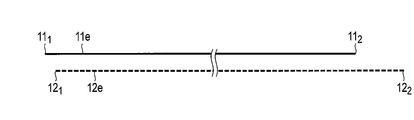
- the positive electrode 11 is indicated by a thick line
- the negative electrode 12 is indicated by a thin line
- the two separators 13 are indicated by a broken line.
- a gap is shown between the positive electrode 11, the negative electrode 12, and the separator 13 so that the arrangement of the positive electrode 11, the negative electrode 12, and the separator 13 can be clearly grasped.
- the positive electrode 11 includes a strip-shaped positive electrode current collector 11a and a positive electrode layer 11b (one positive electrode layer 11b is not shown) formed on both surfaces thereof.
- the positive electrode current collector 11a includes a portion 11c where the positive electrode layer 11b is not formed on the surface. This portion 11c can serve as a positive electrode tab.
- the positive electrode 11 includes a first end surface 11 1 shown in FIGS. 2A and 2B, and a 2 second end surface 11 shown in FIG. 1 and FIGS. 2A and 2B. As is apparent from FIG. 2B, the positive electrode 11 extends from the first end surface 11 1 to the second end surface 11 2 . In other words, the first end surface 11 1 and the second end surface 11 2 of the positive electrode 11 are short sides of the strip-shaped positive electrode 11, respectively.
- the positive electrode tab 11 c shown in FIG. 1 extends from the first end surface 11 1 of the positive electrode 11 to the second end surface 11 2 .
- the negative electrode 12 includes a strip-shaped negative electrode current collector 12a and negative electrode layers 12b (one negative electrode layer 12b is not shown) formed on both surfaces thereof.
- the negative electrode current collector 12a includes a portion 12c where the negative electrode layer 12b is not formed on the surface. This portion 12 can serve as a negative electrode tab.
- Negative electrode 12 includes a first end surface 12 1 shown in FIGS. 2A and 2B, and FIG. 1 and a second end surface shown in FIGS. 2A and 2B 12 2. As is apparent from Figure 2B, the negative electrode 12 extends from the first end face 12 1 to the second end surface 12 2. In other words, the first end surface 12 1 and second end faces 12 2 of the negative electrode 12, respectively, are short side of a strip-shaped anode 12. Although not clearly shown, the negative electrode tab 12 c shown in FIG. 1 extends from the first end surface 12 1 of the negative electrode 12 to the second end surface 12 2 .
- a separator 13, a negative electrode 12, a separator 13, and a positive electrode 11 are laminated in this order to form a laminated body 1.
- the positive electrode tab 11 c and the negative electrode tab 12 c extend from the laminate 1 in opposite directions.
- the laminated body 1 is wound into a flat shape with the direction RR ′ shown in FIG. 1 as a winding axis to form a wound electrode group 1.
- the wound electrode group 1 includes an innermost circumference 1A and an outermost circumference 1B shown in FIGS. 1 and 2A. In the developed view shown in Figure 2B, it illustrates the first end surface 12 of the first end surface 11 1 and the negative electrode 12 of the positive electrode 11 positioned at the innermost circumference 1A of the wound electrode assembly 1 at the left end.
- the right end shows the wound second end surface 12 of the second end surface 11 2 and the negative electrode 12 of the positive electrode 11 positioned in the outermost periphery 1B of the electrode group 1 2.
- the outermost periphery 1B of the wound electrode group 1 is a portion developed in FIG.
- the positive electrode 11 in the wound electrode group 1 is formed with a bent portion 11d on the innermost circumference 1A by winding the laminated body 1 into a flat shape.
- the negative electrode 12 is formed with a bent portion 12d on the innermost circumference 1A by winding the laminated body 1 into a flat shape.
- the separator 13 is wound on the first bent portion 13b in contact with the bent portion 12d of the negative electrode 12 and the bent portion 11d of the positive electrode 11 in the innermost circumference 1A by winding the laminated body 1 into a flat shape.
- a second bent portion 13a is formed in contact therewith.
- the innermost circumference 1A of the wound electrode assembly 1, to the first and portion 11A from the end face 11 1 to bent portions 11d, bent portion 12d from the first end surface 12 1 of the negative electrode 12 of the positive electrode 11 Part 12B and a part 13A of the separator 13 are included.
- the bent portion 11d of the positive electrode 11 and the bent portion 12d of the negative electrode 12 are shown as if they were curved portions.
- the positive electrode 11 is bent so that a fold is formed in the positive electrode current collector 11a in the bent portion 11d
- the negative electrode 12 is bent so that a fold is generated in the negative electrode current collector 12a in the bent portion 12d. It has been.
- An end portion 11e adjacent to the first end surface 111 of the positive electrode 11 included in the innermost circumference 1A of the wound electrode group 1 shown in FIG. 2A has both surfaces 11e-1 and 11e-2 through the separator 13. Opposite the negative electrode 12. Similarly, the ends 12e adjacent the first end surface 12 1 of the negative electrode 12, both surfaces 12e-1 and 12e-2 is opposed to the positive electrode 11 via a separator 13.
- the length of the portion 11A contained in the innermost 1A of the electrode group 1 of the positive electrode 11, that is, the length up to the bent portion 11d of the first end face 11 1 from the positive electrode 11 of the positive electrode 11 L C [mm].
- the length of the separator 13 on the innermost circumference 1A that is, the length from the bent portion 13a of the separator 13 to the bent portion 13b of the separator 13 is L [mm].
- the length L of the separator 13 on the innermost circumference 1A, the length L C of the positive electrode 11, and the length L A of the negative electrode 12 are set to be 0.1. 01 ⁇ (2L ⁇ L A ⁇ L C ) /L ⁇ 0.8 is satisfied.
- one negative electrode 12 comprising a portion 11B of the second end face 11 2 positive electrode 11 including a second end surface 12 2 Part 12B.
- the part 12B of the negative electrode 12 faces the part 11B of the positive electrode 11 with the separator 13 interposed therebetween, and is located outside the part 11B of the positive electrode 11.
- a part 13 ⁇ / b> B of the two separators 13 is disposed outside the part 12 ⁇ / b> B of the negative electrode 12.
- 2 sheets of separators 13 are wound so as to surround the end surface 12 2 second of the second end face 11 2 and the negative electrode 12 of the cathode 11.
- a flat wound electrode group is provided.
- the negative electrode includes a negative electrode active material having an operating potential nobler than 1.0 V (vs. Li / Li + ). Further, in the innermost circumference of the wound electrode group, both surfaces of the end portion of the positive electrode are opposed to the negative electrode through the separator, and both surfaces of the end portion of the negative electrode are opposed to the positive electrode through the separator. Thanks to these, the flat wound electrode group according to the first embodiment can realize a non-aqueous electrolyte battery that can exhibit high energy density and excellent life characteristics.
- a nonaqueous electrolyte battery According to the second embodiment, a nonaqueous electrolyte battery is provided.
- This nonaqueous electrolyte battery includes the wound electrode group according to the first embodiment and a nonaqueous electrolyte.
- the nonaqueous electrolyte battery according to the second embodiment may further include an exterior member that houses a wound electrode group and a nonaqueous electrolyte.
- the nonaqueous electrolyte battery according to the second embodiment further includes a positive electrode terminal electrically connected to the positive electrode of the wound electrode group and a negative electrode terminal electrically connected to the negative electrode of the wound electrode group. Can be provided. Each of the positive electrode terminal and the negative electrode terminal can be attached to the exterior member with an insulating member interposed therebetween, for example.
- Nonaqueous electrolyte As a nonaqueous electrolyte, what is prepared by dissolving electrolyte (for example, lithium salt) in a nonaqueous solvent can be used.
- electrolyte for example, lithium salt
- non-aqueous solvent examples include ethylene carbonate (EC), propylene carbonate (PC), butylene carbonate (BC), dimethyl carbonate (DMC), diethyl carbonate (DEC), ethyl methyl carbonate (EMC), ⁇ -butyrolactone ( ⁇ -BL), sulfolane, acetonitrile, 1,2-dimethoxyethane, 1,3-dimethoxypropane, dimethyl ether, tetrahydrofuran (THF), 2-methyltetrahydrofuran and the like.
- Nonaqueous solvents may be used alone or in combination of two or more.
- Examples of the electrolyte include lithium perchlorate (LiClO 4 ), lithium hexafluorophosphate (LiPF 6 ), lithium tetrafluoroborate (LiBF 4 ), lithium hexafluoroarsenide (LiAsF 6 ), and trifluoromethanesulfone.
- a lithium salt such as lithium acid lithium (LiCF 3 SO 3 ) can be given.
- the electrolyte may be used alone or in combination of two or more.
- the amount of electrolyte dissolved in the non-aqueous solvent is preferably 0.2 mol / L to 3 mol / L. If the electrolyte concentration is too low, sufficient ionic conductivity may not be obtained. On the other hand, if the input amount of the electrolyte to the nonaqueous solvent is too high, the electrolyte may not be completely dissolved in the nonaqueous solvent.
- the exterior member is preferably rectangular.
- the exterior member that can be included in the nonaqueous electrolyte battery according to the second embodiment is not limited to a square shape, and various shapes can be used depending on the application.
- a metal exterior member can be used.
- a material for the exterior member for example, aluminum, aluminum alloy, iron (Fe), nickel (Ni) plated iron, stainless steel (SUS), or the like can be used.
- the exterior member may be made of, for example, a laminate film.
- a laminate film a film comprising a metal layer and two resin layers sandwiching the metal layer can be used.
- Positive electrode terminal and negative electrode terminal It is desirable to form the positive electrode terminal and the negative electrode terminal from, for example, aluminum or an aluminum alloy.
- connection between the positive electrode terminal and the positive electrode can be made, for example, via a positive electrode lead.
- connection between the negative electrode terminal and the negative electrode can be made, for example, via a negative electrode lead.
- the positive electrode lead and the negative electrode lead are preferably formed from, for example, aluminum or an aluminum alloy.
- a resin can be used as a material of the insulating member.
- the resin used for the insulating member any resin can be used as long as it is resistant to the electrolytic solution.
- FIG. 3 is a schematic perspective view of an example nonaqueous electrolyte battery according to the second embodiment.
- 4 is an exploded perspective view of one of the nonaqueous electrolyte batteries shown in FIG.
- FIG. 5 is a further exploded perspective view of the nonaqueous electrolyte battery shown in FIG.
- the nonaqueous electrolyte secondary battery 100 of this example includes an exterior member 111, an electrode group 1 housed in the exterior member 111, and a nonaqueous electrolysis impregnated in the electrode group 1. It is a square nonaqueous electrolyte battery comprising a liquid (not shown).
- the electrode group 1 is the flat wound electrode group 1 described with reference to FIG. 1 and FIGS. 2A and 2B. A portion of the electrode group 1 excluding the positive electrode tab 11 c and the negative electrode tab 12 c is covered with an insulating tape 10.
- the exterior member 111 includes a bottomed rectangular cylindrical metal container 111a having an opening, and a rectangular plate-shaped sealing body 111b disposed in the opening of the container 111a. .
- the sealing body 111b is joined to the opening of the container 111a by welding such as laser welding.
- the sealing body 111b has two through holes (not shown) and an inlet (not shown).
- the nonaqueous electrolyte secondary battery 100 of this example further includes a positive electrode lead 6 and a negative electrode lead 7.
- the positive electrode lead 6 has a connection plate 6a having a through-hole 6b, and a current collecting portion 6c that bifurcates from the connection plate 6a and extends downward.
- the negative electrode lead 7 includes a connection plate 7a having a through hole 7b, and a current collecting portion 7c branched from the connection plate 7a and extending downward.
- the insulator 8 is disposed on the back surface of the sealing body 111b.
- the insulator 8 has a first recess 8a and a second recess 8b on the back surface.
- a through hole 8a ′ and a through hole 8b ′ are opened in the first recess 8a and the second recess 8b, respectively, and each of the through holes 8a ′ and 8b ′ communicates with the through hole of the sealing body 111b. is doing.
- a connection plate 6a for the positive electrode lead 6 is disposed in the first recess 8a, and a connection plate 7a for the negative electrode lead 7 is disposed in the second recess 8b.
- the insulator 8 has a through hole 8c communicating with the inlet of the sealing body 111b.
- the positive electrode lead 6 is joined between the bifurcated current collecting part 6c with the outer periphery of the positive electrode tab 11c of the electrode group 1 sandwiched therebetween.
- the negative electrode lead 7 is joined between the bifurcated current collecting part 7c with the outer periphery of the negative electrode tab 12c of the electrode group 2 sandwiched therebetween.
- the non-aqueous electrolyte secondary battery 100 of this example includes two insulating members 9a.
- One insulating member 9a covers the joint between the positive electrode lead 6 and the positive electrode tab 11c.
- the other insulating member 9a covers the joint between the negative electrode lead 7 and the negative electrode tab 12c.
- the two insulating members 9a are each fixed to the electrode group 2 by an insulating tape 9b folded in half.
- the nonaqueous electrolyte secondary battery 100 of this example further includes a positive electrode terminal 113 and a negative electrode terminal 114.
- the positive electrode terminal 113 includes a rectangular head portion 113a and a shaft portion 113b extending downward from the back surface of the head portion 113a.
- the negative electrode terminal 114 includes a rectangular head portion 114a and a shaft portion 114b extending downward from the back surface of the head portion 114a.
- the positive electrode terminal 113 and the negative electrode terminal 114 are respectively disposed on the upper surface of the sealing body 111b via an insulating gasket 115.
- the shaft portion 113b of the positive electrode terminal 113 is inserted into the through hole 115a of the insulating gasket 115, the through hole of the sealing body 111b, the through hole 8a 'of the insulator 8, and the through hole 6b of the connection plate 6a of the positive electrode lead 6, It is fixed by caulking.
- the shaft portion 114b of the negative electrode terminal 114 is inserted into the through hole 115a of the insulating gasket 115, the through hole of the sealing body 111b, the through hole 8b ′ of the insulator 8, and the through hole 7b of the connection plate 7a of the negative electrode lead 7, They are caulked and fixed. Thereby, the positive electrode terminal 113 and the positive electrode lead 6 are electrically connected, and the negative electrode terminal 114 and the negative electrode lead 7 are electrically connected.
- the nonaqueous electrolyte battery 100 having the above-described configuration, the nonaqueous electrolyte was injected into the container 111a after the electrode group 2 was accommodated in the container 111a and the sealing body 111b was joined to the opening of the container 111a. Can be done through the inlet. After injecting the nonaqueous electrolyte, as shown in FIG. 3, the exterior member 111 can be sealed by fitting a metal sealing plug 123 into the inlet and welding it.
- the nonaqueous electrolyte battery according to the second embodiment includes the flat wound electrode group according to the first embodiment, it can exhibit a high energy density and excellent life characteristics.
- Example 1 In Example 1, a non-aqueous electrolyte secondary battery having the same structure as the non-aqueous electrolyte secondary battery 100 shown in FIGS. 3 to 5 having the wound electrode group 1 shown in FIGS. 1 and 2A and 2B. A battery was produced.
- lithium nickel cobalt manganese composite oxide LiNi 1/3 Co 1/3 Mn 1/3 O 2 and lithium cobalt composite oxide LiCoO 2 were prepared as positive electrode active materials. These were mixed so that LiNi 1/3 Co 1/3 Mn 1/3 O 2 and LiCoO 2 were 2: 1 to obtain an active material mixture.
- This active material mixture, acetylene black as a conductive agent, graphite as a further conductive agent, and polyvinylidene fluoride as a binder were mixed at a mass ratio of 100: 2: 3: 3.
- the mixture thus obtained was charged into N-methyl-2-pyrrolidone as a solvent, and this was kneaded and stirred with a planetary mixer to prepare a positive electrode slurry.
- an aluminum foil having a thickness of 20 ⁇ m as a positive electrode current collector was prepared.
- This aluminum foil had a strip shape extending from the first end face to the second end face.
- the positive electrode slurry prepared previously was applied to both surfaces of the aluminum foil in a coating apparatus so that the coating amount per unit area was 70 g / m 2 . At this time, the positive electrode slurry was not applied to a part of the aluminum foil, and a strip-shaped positive electrode slurry uncoated portion extending in the direction from the first end surface to the second end surface of the aluminum foil was left.
- the coating film thus obtained was dried. Subsequently, the dried coating film and aluminum foil were rolled in a roll press machine so that the electrode density was 3.4 g / cc. Thus, the positive electrode 11 including the positive electrode current collector and the positive electrode layer formed on the surface of the positive electrode current collector was obtained.
- lithium titanate Li 4 Ti 5 O 12 was prepared as a negative electrode active material.
- This active material, graphite as a conductive agent, and polyvinylidene fluoride as a binder were mixed at a mass ratio of 100: 15: 4.
- the mixture thus obtained was charged into N-methyl-2-pyrrolidone as a solvent, and this was kneaded and stirred with a planetary mixer to prepare a negative electrode slurry.
- an aluminum foil having a thickness of 20 ⁇ m as a negative electrode current collector was prepared.
- This aluminum foil had a strip shape extending from the first end face to the second end face.
- the negative electrode slurry prepared previously was applied to both surfaces of the aluminum foil in a coating apparatus so that the coating amount per unit area was 65 g / m 2 . At this time, the negative electrode slurry was not applied to a part of the aluminum foil, and a strip-shaped negative electrode slurry uncoated portion extending in the direction from the first end surface to the second end surface of the aluminum foil was left.
- the coating film thus obtained was dried. Subsequently, the dried coating film and aluminum foil were rolled in a roll press machine so that the electrode density was 2.4 g / cc. Thus, the negative electrode 12 including the negative electrode current collector and the negative electrode layer formed on the surface of the negative electrode current collector was obtained.
- this laminated body 1 was moved to the winding apparatus.
- the separator 13 and the positive electrode 11 were bent first.
- the negative electrode 12 was further added, and the entire laminate was bent and wound in a spiral shape.
- the angle of the first core is adjusted so that the length L A of the negative electrode 12 with the innermost circumference 1A is 69.6 mm and the length L C of the positive electrode 11 with the innermost circumference 1A is 69.7 mm. did.
- the wound body thus obtained was pressed to obtain a flat wound electrode group 1.
- the insulator 8 was disposed on the back surface of the aluminum sealing body 111b.
- the head portion 113a of the positive electrode terminal 113 is disposed on the upper surface of the sealing body 111b via the insulating gasket 115, and the shaft portion 113b of the positive electrode terminal 113 is disposed on one through hole of the sealing body 111b and the through hole 8a of the insulator 8. Inserted into '.
- the head portion 114a of the negative electrode terminal 114 is disposed on the upper surface of the sealing body 111b via the insulating gasket 115, and the shaft portion 114b is inserted into the other through hole of the sealing body 111b and the through hole 8b ′ of the insulating body 8. did.
- a sealing body 111b as shown in FIGS. 4 and 5 was obtained.
- the positive electrode tab 11c of the wound electrode group 1 produced previously was sandwiched between the forked collectors 6c of the positive electrode lead 6, and the positive electrode tab 11c and the positive electrode lead 6 were welded in this state.
- the negative electrode tab 12c of the wound electrode group 1 was sandwiched between the bifurcated current collecting portions 7c of the negative electrode lead 7, and the negative electrode tab 12c and the negative electrode lead 7 were welded in this state.
- the positive electrode terminal 113 was caulked and fixed to the connection plate 6 a of the positive electrode lead 6.
- the negative electrode terminal 114 was fixed by caulking to the connection plate 7 a of the negative electrode lead 7. In this way, the electrode group 2 and the sealing body 111b were integrated.
- one insulating member 9a was put on the positive electrode lead 6 and the positive electrode tab 11c so as to fix them. Similarly, another insulating member 9a was put on the negative electrode lead 7 and the negative electrode tab 12c so as to fix them. Subsequently, these insulating members 9a were each fixed with an insulating tape 9b.
- the unit of the insulating member 9a, the positive electrode lead 6 and the positive electrode tab 11c fixed in this manner and the unit of the insulating member 9a, the negative electrode lead 7 and the negative electrode tab 12c were inserted into an aluminum container 111a. Subsequently, the sealing body 111b was welded with the laser to the opening part of the container 111a, and the battery unit 100 was produced.
- the produced battery unit 100 had a rectangular parallelepiped shape with a width of 10 mm, a height of 10 mm, and a thickness of 30 mm.
- the non-aqueous electrolyte battery 100 was initially charged. The initial charging was performed at a constant voltage until the current value reached 0.01 C after constant current charging at 0.2 C up to 2.8 V at 25 ° C.
- the non-aqueous electrolyte battery 100 that was initially charged was heated in the atmosphere at 60 ° C. for 150 hours, and then charged at a constant current of 0.2 C to 2.8 V at 25 ° C. Thereafter, the battery unit 100 was charged by constant voltage charging until the current value reached 0.01C. Further, the battery unit 100 was discharged at 0.33 C until the voltage value became 1.3 V, and the discharge capacity was measured. The measured discharge amount was taken as the rated capacity of the nonaqueous electrolyte battery 100 of Example 1. The rated capacity of the nonaqueous electrolyte battery 100 of Example 1 was 22.23 Ah.
- the non-aqueous electrolyte battery 100 was charged at a constant current of 0.2 C up to 2.8 V at 25 ° C., and then the current value was 0.01 C by constant voltage charging.
- the nonaqueous electrolyte battery 100 was stored for 1 month in a 25 ° C. atmosphere.
- the nonaqueous electrolyte battery 100 after storage was discharged at 0.33 C in a 25 ° C. atmosphere until the voltage value became 1.3 V, the discharge capacity was measured, and this discharge capacity was measured for the nonaqueous electrolyte battery 100 of Example 1. It was set as the capacity after storage.
- the capacity of the nonaqueous electrolyte battery 100 of Example 1 was 19.23 Ah. That is, the self-discharge amount by storage of the nonaqueous electrolyte battery 100 of Example 1 was 3.00 Ah.
- wound electrode group 1 A cross-sectional observation of the wound electrode group 1 of the nonaqueous electrolyte battery 100 of Example 1 was performed.
- the cross section of the wound electrode group 1 had a structure similar to the structure schematically shown in FIG. 2A. That is, the wound electrode group 1 includes a portion 11A from the first end surface 11 1 of the positive electrode 11 to the bent portion 11d of the positive electrode 11, and a first end surface 12 1 of the negative electrode 12 to the bent portion 12d of the negative electrode 12.
- An innermost circumference 1A including a portion 12A and a portion 13A from the second bent portion 13a that contacts the bent portion 11d of the positive electrode 11 to the first bent portion 13b that contacts the bent portion 12d of the negative electrode 12 in the separator 13 Included.
- both surfaces 11e-1 and 11e-2 of the end portion 11e adjacent to the first end surface 111 of the positive electrode 11 face the negative electrode 12 with the separator 13 interposed therebetween.
- both sides 12e-1 and 12e-2 of the first end portion 12e adjacent the end face 12 1 of the negative electrode 12 was opposite to the positive electrode 13 via a separator 13.
- the wound electrode group 1 includes a portion 11B including the second end surface 11 2 of the positive electrode 11, a portion 12B including the second end surface 12 2 of the negative electrode 12, and an end portion 13B of the separator 13. The outer periphery 1B was included.
- the part 12 ⁇ / b> B of the negative electrode 12 faces the part 11 ⁇ / b> B of the positive electrode 11 through the separator 13, and is located outside the part 11 ⁇ / b> B of the positive electrode 11. Further, a part 13 ⁇ / b> B of the two separators 13 was disposed outside the part 12 ⁇ / b> B of the negative electrode 12. The two separators 13 has been wound so as to surround the end surface 12 2 second of the second end face 11 2 and the negative electrode 12 of the cathode 11.
- the length L C of the positive electrode 11, the length L A of the negative electrode 12, and the length L of the separator in the innermost circumference 1A of the wound electrode group 1 of the nonaqueous electrolyte battery 100 of Example 1 are described first. Measured according to the procedure described above. The results are shown in Table 1 below. The (2L ⁇ L A ⁇ L C ) / L of the wound electrode group 1 of the nonaqueous electrolyte battery 100 of Example 1 was 0.01.
- the rated capacity was discharged at 0.2C. Thereafter, the battery was disassembled, and a 1 cm 2 negative electrode 12 was taken out and washed with ethyl methyl carbonate to obtain a negative electrode for a tripolar battery.
- the opposing area of the positive electrode 11 and the negative electrode 12 was examined at the time of dismantling, it was 1.12 m 2 .
- a value obtained by dividing the rated capacity of the battery 100 by the facing area of 1.12 m 2 was defined as the rated capacity of the tripolar battery.
- a tripolar battery having a negative electrode 12 as a working electrode, metallic lithium as a counter electrode, and metallic lithium as a reference electrode was produced in an argon atmosphere. While measuring the voltage between the working electrode and the reference electrode, this tripolar battery is charged with the rated capacity of the tripolar battery by supplying a current of 0.2 C between the working electrode and the counter electrode. The end-stage closed circuit voltage was examined. As a result, the closed circuit voltage is 1.33 V vs.. Li / Li + . This potential was taken as the operating potential of the negative electrode 12. The direction in which Li was inserted into the negative electrode 12 was defined as charging.
- Example 2 In Example 2, when the laminated body 1 is formed, the end 11e (the protruding portion of the positive electrode 11) of the positive electrode 11 that is adjacent to the first end surface 111 of the positive electrode 11 and does not face the negative electrode 12 is used.
- the length L A of the innermost circumference 1A of the negative electrode 12 was 50.0 mm during the winding and the length was 75.0 mm, and the length of the positive electrode 11 of the innermost circumference 1A was 50.0 mm.
- a nonaqueous electrolyte secondary battery 100 was constructed in the same procedure as in Example 1 except that the angle of the first core was adjusted so that L C was 55.0 mm.
- the rated capacity of the nonaqueous electrolyte battery 100 of Example 2 was measured in the same procedure as described in Example 1.
- the rated capacity of the nonaqueous electrolyte battery 100 of Example 2 was 22.12 Ah.
- the charge / discharge cycle test and the storage test were performed on the non-aqueous electrolyte secondary battery 100 in the same procedure as in Example 1. After storage, the nonaqueous electrolyte battery 100 was discharged at 0.33 C in a 25 ° C. atmosphere until the voltage value became 1.3 V, and the discharge capacity was measured. As a result, a capacity of 19.10 Ah was obtained. That is, the self-discharge amount by storage of the nonaqueous electrolyte battery 100 of Example 2 was 3.02 Ah.
- the cross section of the wound electrode group 1 of Example 2 had a structure similar to the structure schematically shown in FIG. As apparent from the comparison between FIGS. 2A and 6, wound electrode assembly 1 of Example 2, the innermost 1A, 1 single bent portions of the first end face 11 1 from the separator 13 of the positive electrode 11 The distance to 13b was larger than that of the wound electrode group 1 shown in FIG. 2A, that is, the wound electrode group 1 of Example 1. Further, wound electrode assembly 1 of Example 2, the innermost 1A, the distance from the first end surface 12 1 of the negative electrode 12 to one of the bent portions 13a of the separator 13, wound as shown in FIG. 2A It was larger than that of the electrode group 1, that is, the wound electrode group 1 of Example 1. In other respects, the cross-sectional structure of the wound electrode group 1 of Example 2 was the same as that of Example 1.
- the length L C of the positive electrode 11, the length L A of the negative electrode 12, and the length L of the separator in the innermost circumference 1A of the wound electrode group 1 of the nonaqueous electrolyte battery 100 of Example 2 will be described first. Measured according to the procedure described above. The results are shown in Table 1 below. The (2L ⁇ L A ⁇ L C ) / L of the wound electrode group 1 of the nonaqueous electrolyte battery 100 of Example 2 was 0.50.
- Example 3 In Example 3, when the laminated body 1 is formed, the end 11e (the protruding portion of the positive electrode 11) of the positive electrode 11 that is adjacent to the first end surface 111 of the positive electrode 11 and does not face the negative electrode 12 is used.
- the length L A of the innermost circumference 1A of the negative electrode 12 was 50.0 mm during the winding and the length of the positive electrode 11 was the innermost circumference 1A.
- the nonaqueous electrolyte secondary battery 100 was configured by the same procedure as in Example 1 except that the angle of the first core was adjusted so that L C was 34.0 mm.
- the rated capacity of the nonaqueous electrolyte battery 100 of Example 3 was measured in the same procedure as described in Example 1.
- the rated capacity of the nonaqueous electrolyte battery 100 of Example 3 was 22.08 Ah.
- the charge / discharge cycle test and the storage test were performed on the non-aqueous electrolyte secondary battery 100 in the same procedure as in Example 1. After storage, the nonaqueous electrolyte battery 100 was discharged at 0.33 C in a 25 ° C. atmosphere until the voltage value became 1.3 V, and the discharge capacity was measured. As a result, a capacity of 19.07 Ah was obtained. That is, the self-discharge amount by storage of the nonaqueous electrolyte battery 100 of Example 3 was 3.01 Ah.
- the cross section of the wound electrode group 1 of Example 3 had a structure similar to the structure schematically shown in FIG.
- the wound electrode group 1 of Example 3 has a length of 1 of the separator 13 from the first end face 111 of the positive electrode 11 on the innermost periphery 1A.
- the distance to the two bent portions 13b is larger than that of the wound electrode group 1 shown in FIG. 2A, that is, the wound electrode group 1 of Example 1, and further, the wound electrode group 1 shown in FIG. It was larger than that of the wound electrode group 1 of Example 2.
- wound electrode assembly 1 of Example 3 the innermost 1A, the distance from the first end surface 12 1 of the negative electrode 12 to one of the bent portions 13a of the separator 13, the wound-type of Example 1 It was larger than that of the electrode group 1 and was the same as that of the wound electrode group 1 of Example 2.
- the cross-sectional structure of the wound electrode group 1 of Example 3 was the same as that of Example 1 and Example 2.
- the length L C of the positive electrode 11, the length L A of the negative electrode 12, and the length L of the separator in the innermost circumference 1A of the wound electrode group 1 of the nonaqueous electrolyte battery 100 of Example 3 are described first. Measured according to the procedure described above. The results are shown in Table 1 below. The (2L ⁇ L A ⁇ L C ) / L of the wound electrode group 1 of the nonaqueous electrolyte battery 100 of Example 3 was 0.80.
- Example 4 In Example 4, when forming the laminated body 1, the end 11 e of the positive electrode 11 adjacent to the first end surface 111 of the positive electrode 11 and not facing the negative electrode 12 (the protruding portion of the positive electrode 11). the length was laminated such a 66.0, and the length of the wound during the length L a is 30.0mm next negative electrode 12 of the innermost 1A, the positive electrode 11 of the innermost 1A
- the nonaqueous electrolyte secondary battery 100 was configured by the same procedure as in Example 1 except that the angle of the first core was adjusted so that L C was 26.0 mm.
- the rated capacity of the nonaqueous electrolyte battery 100 of Example 4 was measured by the same procedure as described in Example 1.
- the rated capacity of the nonaqueous electrolyte battery 100 of Example 4 was 22.01 Ah.
- the charge / discharge cycle test and the storage test were performed on the non-aqueous electrolyte secondary battery 100 in the same procedure as in Example 1. After storage, the nonaqueous electrolyte battery 100 was discharged at 0.33 C in a 25 ° C. atmosphere until the voltage value became 1.3 V, and the discharge capacity was measured. As a result, a capacity of 19.05 Ah was obtained. That is, the amount of self-discharge due to storage for the nonaqueous electrolyte battery 100 of Example 4 was 2.96 Ah.
- the length L C of the positive electrode 11, the length L A of the negative electrode 12, and the length L of the separator in the innermost circumference 1A of the wound electrode group 1 of the nonaqueous electrolyte battery 100 of Example 4 will be described first. Measured according to the procedure described above. The results are shown in Table 1 below. The (2L ⁇ L A ⁇ L C ) / L of the wound electrode group 1 of the nonaqueous electrolyte battery 100 of Example 4 was 1.20.
- Example 5 In Example 5, when forming the laminated body 1, the end 11 e of the positive electrode 11 adjacent to the first end surface 111 of the positive electrode 11 and not facing the negative electrode 12 (the protruding portion of the positive electrode 11).
- the length L A of the innermost circumference 1A of the negative electrode 12 was 15.0 mm and the length of the positive electrode 11 of the innermost circumference 1A was increased.
- a nonaqueous electrolyte secondary battery 100 was configured by the same procedure as in Example 1 except that the angle of the first core was adjusted so that L C was 20.0 mm.
- the rated capacity of the nonaqueous electrolyte battery 100 of Example 5 was measured in the same procedure as described in Example 1.
- the rated capacity of the nonaqueous electrolyte battery 100 of Example 5 was 22.09 Ah.
- the charge / discharge cycle test and the storage test were performed on the non-aqueous electrolyte secondary battery 100 in the same procedure as in Example 1. After storage, the nonaqueous electrolyte battery 100 was discharged at 0.33 C in a 25 ° C. atmosphere until the voltage value became 1.3 V, and the discharge capacity was measured. As a result, a capacity of 19.05 Ah was obtained. That is, the self-discharge amount by storage of the nonaqueous electrolyte battery 100 of Example 5 was 3.04 Ah.
- the length L C of the positive electrode 11, the length L A of the negative electrode 12, and the length L of the separator in the innermost circumference 1A of the wound electrode group 1 of the nonaqueous electrolyte battery 100 of Example 5 will be described first. Measured according to the procedure described above. The results are shown in Table 1 below. The (2L ⁇ L A ⁇ L C ) / L of the wound electrode group 1 of the nonaqueous electrolyte battery 100 of Example 5 was 1.50.
- Example 6 In Example 6, when the laminated body 1 is formed, of the positive electrode 11, the end portion 11 e adjacent to the first end surface 111 of the positive electrode 11 and not facing the negative electrode 12 (the protruding portion of the positive electrode 11).
- the length L A of the innermost peripheral 1A negative electrode 12 is 0.3 mm
- the length of the positive electrode 11 of the innermost peripheral 1A is about 0.3 mm.
- a nonaqueous electrolyte secondary battery 100 was configured by the same procedure as in Example 1 except that the angle of the first core was adjusted so that L C was 0.4 mm.
- the rated capacity of the nonaqueous electrolyte battery 100 of Example 6 was measured in the same procedure as described in Example 1.
- the rated capacity of the nonaqueous electrolyte battery 100 of Example 6 was 22.26 Ah.
- the charge / discharge cycle test and the storage test were performed on the non-aqueous electrolyte secondary battery 100 in the same procedure as in Example 1. After storage, the nonaqueous electrolyte battery 100 was discharged at 0.33 C in a 25 ° C. atmosphere until the voltage value became 1.3 V, and the discharge capacity was measured. As a result, a capacity of 19.22 Ah was obtained. That is, the self-discharge amount by storage of the nonaqueous electrolyte battery 100 of Example 6 was 3.04 Ah.
- the length L C of the positive electrode 11, the length L A of the negative electrode 12, and the length L of the separator in the innermost circumference 1A of the wound electrode group 1 of the nonaqueous electrolyte battery 100 of Example 6 will be described first. Measured according to the procedure described above. The results are shown in Table 1 below. The (2L ⁇ L A ⁇ L C ) / L of the wound electrode group 1 of the nonaqueous electrolyte battery 100 of Example 6 was 1.99.
- Example 7 In Example 7, except that bronze-type titanium oxide (TiO 2 (B)) was used as the negative electrode active material and that the coating amount of the negative electrode slurry was adjusted so that the coating amount per unit area was 80 g / m 2.
- a non-aqueous electrolyte secondary battery 100 was configured by the same procedure as in Example 1 above.
- the rated capacity of the nonaqueous electrolyte battery 100 of Example 7 was measured in the same procedure as described in Example 1.
- the rated capacity of the nonaqueous electrolyte battery 100 of Example 7 was 23.86 Ah.
- the charge / discharge cycle test and the storage test were performed on the non-aqueous electrolyte secondary battery 100 in the same procedure as in Example 1. After storage, the nonaqueous electrolyte battery 100 was discharged at 0.33 C in a 25 ° C. atmosphere until the voltage value became 1.3 V, and the discharge capacity was measured. As a result, a capacity of 20.95 Ah was obtained. That is, the self-discharge amount by storage of the nonaqueous electrolyte battery 100 of Example 7 was 2.91 Ah.
- Example 7 cross-sectional observation of the wound electrode group 1 of the nonaqueous electrolyte battery 100 of Example 7 was performed.
- the cross section of the wound electrode group 1 had a structure similar to the structure schematically shown in FIG. 2A. That is, the cross-sectional structure of the wound electrode group 1 of Example 7 was the same as that of Example 1.
- the operating potential of the negative electrode 12 of the wound electrode group 1 of the nonaqueous electrolyte battery 100 of Example 7 was measured in the same procedure as described in Example 1.
- the operating potential of the negative electrode 12 of Example 7 was 1.1 V (vs. Li / Li + ).
- Comparative Example 1 In Comparative Example 1, when the laminate 1 is formed, the end 11e (the protruding portion of the positive electrode 11) of the positive electrode 11 that is adjacent to the first end surface 111 of the positive electrode 11 and does not face the negative electrode 12 is used.
- the length L A of the innermost peripheral 1A negative electrode 12 was 40.0 mm during the winding, and the length L A of the innermost peripheral 1A was positive.
- a nonaqueous electrolyte secondary battery 100 was configured by the same procedure as in Example 1 except that the angle of the first core was adjusted so that L C was 30.0 mm.
- the rated capacity of the nonaqueous electrolyte battery 100 of Comparative Example 1 was measured in the same procedure as described in Example 1.
- the rated capacity of the nonaqueous electrolyte battery 100 of Comparative Example 1 was 21.89 Ah.
- the charge / discharge cycle test and the storage test were performed on the non-aqueous electrolyte secondary battery 100 in the same procedure as in Example 1. After storage, the nonaqueous electrolyte battery 100 was discharged at 0.33 C in a 25 ° C. atmosphere until the voltage value became 1.3 V, and the discharge capacity was measured. As a result, a capacity of 18.92 Ah was obtained. That is, the self-discharge amount by storage of the nonaqueous electrolyte battery 100 of Comparative Example 1 was 2.97 Ah.
- wound electrode assembly 1 of Comparative Example 1 had a structure similar to the structure schematically shown in FIG.
- wound electrode assembly 1 of Comparative Example 1 the innermost 1A, the first end face 12 1 of the position of the first end surface 11 1 and the negative electrode 12 of the positive electrode 11, winding They were aligned in the direction CC ′ and in the direction NN ′ perpendicular to the winding axis RR ′. Therefore, as shown in FIG.
- the end portion 11e adjacent to the first end surface 111 of the positive electrode 11 is only on one side 11e-1 in the innermost circumference 1A. Faces the negative electrode 12 with the separator 13 interposed therebetween, and the other surface 11e-2 faces the other part of the positive electrode 11.
- the end 12e adjacent to the first end surface 121 of the negative electrode 12 has only one surface 12e-1 facing the positive electrode 11 with the separator 13 therebetween, and the other surface 12e. -2 faced the other part of the negative electrode 12.
- the cross-sectional structure of the wound electrode group 1 of Comparative Example 1 was the same as that of Examples 1 to 7.
- Comparative Example 2 In Comparative Example 2, the same procedure as in Example 2 was used except that graphite was used as the negative electrode active material and that the coating amount of the negative electrode slurry was adjusted so that the coating amount per unit area was 40 g / m 2.
- the nonaqueous electrolyte secondary battery of Comparative Example 1 was constructed.
- the rated capacity of the nonaqueous electrolyte battery 100 of Comparative Example 2 was measured in the same procedure as described in Example 1.
- the rated capacity of the nonaqueous electrolyte battery 100 of Comparative Example 2 was 24.35 Ah.
- the charge / discharge cycle test and the storage test were performed on the non-aqueous electrolyte secondary battery 100 in the same procedure as in Example 1. After storage, the nonaqueous electrolyte battery 100 was discharged at 0.33 C in a 25 ° C. atmosphere until the voltage value became 1.3 V, and the discharge capacity was measured. As a result, a capacity of 5.24 Ah was obtained. That is, the self-discharge amount by storage of the nonaqueous electrolyte battery 100 of Comparative Example 2 was 19.11 Ah.
- the cross section of the wound electrode group 1 had a structure similar to the structure schematically shown in FIG. That is, the cross-sectional structure of the wound electrode group 1 of Comparative Example 2 was the same as that of Example 2.
- the length L C of the positive electrode 11, the length L A of the negative electrode 12, and the length L of the separator in the innermost circumference 1A of the wound electrode group 1 of the nonaqueous electrolyte battery 100 of Comparative Example 2 will be described first. Measured according to the procedure described above. The result was the same as the result of Example 2 as shown in Table 1 below. Therefore, the value of (2L ⁇ L A ⁇ L C ) / L of the wound electrode group 1 of the nonaqueous electrolyte battery 100 of Comparative Example 2 was 0.05.
- the operating potential of the negative electrode 12 of the wound electrode group 1 of the nonaqueous electrolyte battery 100 of Comparative Example 2 was measured in the same procedure as described in Example 1.
- the operating potential of the negative electrode 12 of Comparative Example 2 was 0.3 V (vs. Li / Li + ).
- the non-aqueous electrolyte battery 100 of Examples 1 to 6 was able to suppress self-discharge similarly to the non-aqueous electrolyte battery 100 of Comparative Example 1. This is because, in the nonaqueous electrolyte batteries of Examples 1 to 6, both ends of the end portion 12e of the negative electrode 12 face the positive electrode 11 through the separator 13 in the innermost circumference 1A of the wound electrode group 1. This is because the operating potential of the negative electrode active material included in the negative electrode 12 was nobler than 1.0 V (vs. Li / Li + ), and thus metal deposition on the negative electrode surface could be suppressed. As described above, this fact is proved by confirming the metal distribution on the electrode surface by energy dispersive X-ray spectroscopy.
- the non-aqueous electrolyte 100 of Example 7 is similar to the non-aqueous electrolyte battery 100 of Examples 1 to 6, while suppressing self-discharge, and the non-aqueous electrolyte 100 of Example 1 A rated capacity higher than that of the water electrolyte battery 100 could be shown. From this result, it was proved that the same effect can be obtained even if the negative electrode active material is changed as long as the operating potential is higher than 1.0 V (vs. Li / Li + ).
- the nonaqueous electrolyte battery 100 of Comparative Example 2 using graphite as the negative electrode active material had a significantly higher self-discharge capacity than the nonaqueous electrolyte batteries 100 of Examples 1-7.
- This is considered to be caused by the deposition of metallic lithium on the surface of the negative electrode 12 after storage, as proved from confirmation of the metal distribution on the electrode surface by energy dispersive X-ray spectroscopy.
- one of the causes is that the negative electrode 12 is twisted.
- the twist of the negative electrode 12 is considered to be caused by a large change in the volume of graphite due to the insertion and desorption of lithium.
- Example 8 the nonaqueous electrolyte secondary battery 100 was configured by the same procedure as in Example 1 except for the following points.
- Example 8 the coating amount per unit area of the positive electrode slurry was 140 g / m 2 . Moreover, the positive electrode 11 was obtained by rolling with a roll press so that the electrode density was 3.1 g / cc.
- Example 8 the coating amount per unit area of the negative electrode slurry was set to 135 g / m 2 . Moreover, the negative electrode 12 was obtained by rolling with a roll press so that the electrode density was 2.1 g / cc.
- Example 8 the number of windings in the winding device is reduced from that in Example 1 by the amount that the coating amount of the positive electrode slurry and the coating amount of the negative electrode slurry are larger than in Example 1, so that L A , L A wound electrode group 1 having the same values of C and L as those in Example 1 was produced.
- the rated capacity of the nonaqueous electrolyte battery 100 of Example 8 was measured in the same procedure as described in Example 1.
- the rated capacity of the nonaqueous electrolyte battery 100 of Example 8 was 23.52 Ah.
- the charge / discharge cycle test and the storage test were performed on the non-aqueous electrolyte secondary battery 100 in the same procedure as in Example 1. After storage, the nonaqueous electrolyte battery 100 was discharged at 0.33 C in a 25 ° C. atmosphere until the voltage value became 1.3 V, and the discharge capacity was measured. As a result, a capacity of 20.48 Ah was obtained. That is, the self-discharge amount by storage of the nonaqueous electrolyte battery 100 of Example 8 was 3.04 Ah.
- the length L C of the positive electrode 11, the length L A of the negative electrode 12, and the length L of the separator in the innermost circumference 1A of the wound electrode group 1 of the nonaqueous electrolyte battery 100 of Example 8 will be described first. Measured according to the procedure described above. The results are shown in Table 1 below. The (2L ⁇ L A ⁇ L C ) / L of the wound electrode group 1 of the nonaqueous electrolyte battery 100 of Example 8 was 0.01.
- Example 9 In Example 9, when forming the laminated body 1, the length of the end 11 e (the protruding portion of the positive electrode 11) of the positive electrode 11 that is adjacent to the first end surface 11 1 of the positive electrode 11 and does not face the negative electrode 12.
- the length L A of the negative electrode 12 at the innermost circumference 1A is 67.0 mm during the winding and the length L of the positive electrode 11 at the innermost circumference 1A.
- the nonaqueous electrolyte secondary battery 100 was configured by the same procedure as in Example 8 except that the angle of the first core was adjusted so that C was 65.0 mm.
- the rated capacity of the nonaqueous electrolyte battery 100 of Example 9 was measured in the same procedure as described in Example 1.
- the rated capacity of the nonaqueous electrolyte battery 100 of Example 8 was 22.17 Ah.
- the charge / discharge cycle test and the storage test were performed on the non-aqueous electrolyte secondary battery 100 in the same procedure as in Example 1. After storage, the nonaqueous electrolyte battery 100 was discharged at 0.33 C in a 25 ° C. atmosphere until the voltage value became 1.3 V, and the discharge capacity was measured. As a result, a capacity of 19.13 Ah was obtained. That is, the self-discharge amount by storage of the nonaqueous electrolyte battery 100 of Example 9 was 3.04 Ah.
- the nonaqueous electrolyte 100 of Examples 8 and 9 is also a comparative example while suppressing self-discharge, similarly to the nonaqueous electrolyte battery 100 of Examples 1-7. It was possible to show a higher rated capacity than that of the single nonaqueous electrolyte battery 100. From this result, it was proved that the same effect can be obtained even if the coating amount of the positive electrode and the negative electrode is changed.
- the negative electrode includes a negative electrode active material whose operating potential is nobler than 1.0 V (vs. Li / Li + ). Further, in the innermost circumference of the wound electrode group, both surfaces of the end portion of the positive electrode are opposed to the negative electrode through the separator, and both surfaces of the end portion of the negative electrode are opposed to the positive electrode through the separator. Thanks to these, this wound electrode group can realize a non-aqueous electrolyte battery that can exhibit high energy density and excellent life characteristics.
- SYMBOLS 1 Winding type electrode group (laminated body), 1A ... Innermost circumference, 1B ... Outermost circumference, 6 ... Positive electrode lead, 6a ... Connection plate, 6b ... Through-hole, 6c ... Current collecting part, 7 ... Negative electrode lead, 7a ... Connection plate, 7b ... through hole, 7c ... current collector, 8 ... insulator, 8a ... first recess, 8a '... through hole, 8b ... second recess, 8b' ... through hole, 8c ... through hole , 9a ... insulating member, 9b ... insulating tape, 10 ... insulating tape, 11 ... positive electrode, 11A ...
- Electrolyte battery 111 ... exterior member, 111a ... container, 111b ... sealing body, 113 ... positive electrode terminal, 113a ... head, 113b ... shaft, 114 ... negative electrode terminal, 114a ... head, 114b ... shaft, 115 ... insulation Gasket, 115a ... through hole, 123 ... sealing plug.
Landscapes
- Chemical & Material Sciences (AREA)
- Chemical Kinetics & Catalysis (AREA)
- Electrochemistry (AREA)
- General Chemical & Material Sciences (AREA)
- Engineering & Computer Science (AREA)
- Manufacturing & Machinery (AREA)
- Inorganic Chemistry (AREA)
- Materials Engineering (AREA)
- Secondary Cells (AREA)
- Sealing Battery Cases Or Jackets (AREA)
- Battery Electrode And Active Subsutance (AREA)
Priority Applications (4)
| Application Number | Priority Date | Filing Date | Title |
|---|---|---|---|
| EP15755296.9A EP3113276A4 (de) | 2014-02-25 | 2015-01-28 | Gewalzter elektrodensatz und batterie mit wasserfreiem elektrolyt |
| CN201580010371.0A CN106063021A (zh) | 2014-02-25 | 2015-01-28 | 卷绕型电极组及非水电解质电池 |
| JP2016505114A JPWO2015129376A1 (ja) | 2014-02-25 | 2015-01-28 | 捲回型電極群及び非水電解質電池 |
| US15/230,831 US20160344064A1 (en) | 2014-02-25 | 2016-08-08 | Wound electrode group and nonaqueous electrolyte battery |
Applications Claiming Priority (2)
| Application Number | Priority Date | Filing Date | Title |
|---|---|---|---|
| JP2014034375 | 2014-02-25 | ||
| JP2014-034375 | 2014-02-25 |
Related Child Applications (1)
| Application Number | Title | Priority Date | Filing Date |
|---|---|---|---|
| US15/230,831 Continuation US20160344064A1 (en) | 2014-02-25 | 2016-08-08 | Wound electrode group and nonaqueous electrolyte battery |
Publications (1)
| Publication Number | Publication Date |
|---|---|
| WO2015129376A1 true WO2015129376A1 (ja) | 2015-09-03 |
Family
ID=54008702
Family Applications (1)
| Application Number | Title | Priority Date | Filing Date |
|---|---|---|---|
| PCT/JP2015/052383 Ceased WO2015129376A1 (ja) | 2014-02-25 | 2015-01-28 | 捲回型電極群及び非水電解質電池 |
Country Status (5)
| Country | Link |
|---|---|
| US (1) | US20160344064A1 (de) |
| EP (1) | EP3113276A4 (de) |
| JP (1) | JPWO2015129376A1 (de) |
| CN (1) | CN106063021A (de) |
| WO (1) | WO2015129376A1 (de) |
Cited By (2)
| Publication number | Priority date | Publication date | Assignee | Title |
|---|---|---|---|---|
| CN109478693A (zh) * | 2016-07-15 | 2019-03-15 | 株式会社杰士汤浅国际 | 蓄电元件以及蓄电元件的制造方法 |
| WO2024181045A1 (ja) * | 2023-02-28 | 2024-09-06 | パナソニックエナジー株式会社 | 二次電池 |
Families Citing this family (7)
| Publication number | Priority date | Publication date | Assignee | Title |
|---|---|---|---|---|
| JP6961103B2 (ja) | 2018-09-21 | 2021-11-05 | 株式会社東芝 | 電池及び電池パック |
| US20200313170A1 (en) * | 2019-03-26 | 2020-10-01 | Nanotek Instruments, Inc. | Graphene-encapsulated graphite-supported anode active material for lithium-ion batteries |
| JP7459944B2 (ja) * | 2020-07-22 | 2024-04-02 | 株式会社村田製作所 | 二次電池 |
| CN114204132B (zh) * | 2020-09-18 | 2024-09-17 | 株式会社东芝 | 电极组、二次电池、电池包及车辆 |
| JP7265580B2 (ja) * | 2021-04-26 | 2023-04-26 | プライムプラネットエナジー&ソリューションズ株式会社 | 非水電解質二次電池 |
| EP4418402A4 (de) * | 2022-12-20 | 2025-10-15 | Contemporary Amperex Technology Hong Kong Ltd | Elektrodenanordnung, batteriezelle, batterie und elektrische vorrichtung |
| CN117457965B (zh) * | 2023-12-25 | 2024-04-02 | 天鹏锂能技术(淮安)有限公司 | 一种卷绕电芯 |
Citations (5)
| Publication number | Priority date | Publication date | Assignee | Title |
|---|---|---|---|---|
| JP2008171632A (ja) * | 2007-01-10 | 2008-07-24 | Sanyo Electric Co Ltd | 非水電解質二次電池 |
| JP2011044312A (ja) * | 2009-08-20 | 2011-03-03 | Toshiba Corp | 非水電解質電池および電池パック |
| JP2012043709A (ja) * | 2010-08-20 | 2012-03-01 | Toshiba Corp | 非水電解質電池 |
| WO2013014833A1 (ja) * | 2011-07-25 | 2013-01-31 | パナソニック株式会社 | リチウムイオン二次電池 |
| JP2013251109A (ja) * | 2012-05-31 | 2013-12-12 | Toshiba Corp | 非水電解質電池およびパック電池 |
Family Cites Families (5)
| Publication number | Priority date | Publication date | Assignee | Title |
|---|---|---|---|---|
| WO2000028607A1 (en) * | 1998-11-06 | 2000-05-18 | Japan Storage Battery Co., Ltd. | Non-aqueous electrolytic secondary cell |
| JP4683044B2 (ja) * | 2007-12-28 | 2011-05-11 | Tdk株式会社 | 巻回型電気化学デバイス、及び巻回型電気化学デバイスの製造方法 |
| KR100911999B1 (ko) * | 2008-01-28 | 2009-08-14 | 주식회사 엘지화학 | 절연특성이 향상된 전지 |
| US8574753B2 (en) * | 2009-08-27 | 2013-11-05 | Kabushiki Kaisha Toshiba | Battery comprising a conductive nipping member |
| JP2013062164A (ja) * | 2011-09-14 | 2013-04-04 | Hitachi Maxell Energy Ltd | 電気化学素子用非水電解液および電気化学素子 |
-
2015
- 2015-01-28 CN CN201580010371.0A patent/CN106063021A/zh not_active Withdrawn
- 2015-01-28 EP EP15755296.9A patent/EP3113276A4/de not_active Withdrawn
- 2015-01-28 WO PCT/JP2015/052383 patent/WO2015129376A1/ja not_active Ceased
- 2015-01-28 JP JP2016505114A patent/JPWO2015129376A1/ja active Pending
-
2016
- 2016-08-08 US US15/230,831 patent/US20160344064A1/en not_active Abandoned
Patent Citations (5)
| Publication number | Priority date | Publication date | Assignee | Title |
|---|---|---|---|---|
| JP2008171632A (ja) * | 2007-01-10 | 2008-07-24 | Sanyo Electric Co Ltd | 非水電解質二次電池 |
| JP2011044312A (ja) * | 2009-08-20 | 2011-03-03 | Toshiba Corp | 非水電解質電池および電池パック |
| JP2012043709A (ja) * | 2010-08-20 | 2012-03-01 | Toshiba Corp | 非水電解質電池 |
| WO2013014833A1 (ja) * | 2011-07-25 | 2013-01-31 | パナソニック株式会社 | リチウムイオン二次電池 |
| JP2013251109A (ja) * | 2012-05-31 | 2013-12-12 | Toshiba Corp | 非水電解質電池およびパック電池 |
Non-Patent Citations (1)
| Title |
|---|
| See also references of EP3113276A4 * |
Cited By (3)
| Publication number | Priority date | Publication date | Assignee | Title |
|---|---|---|---|---|
| CN109478693A (zh) * | 2016-07-15 | 2019-03-15 | 株式会社杰士汤浅国际 | 蓄电元件以及蓄电元件的制造方法 |
| US11335956B2 (en) | 2016-07-15 | 2022-05-17 | Gs Yuasa International Ltd. | Energy storage device and method of manufacturing energy storage device |
| WO2024181045A1 (ja) * | 2023-02-28 | 2024-09-06 | パナソニックエナジー株式会社 | 二次電池 |
Also Published As
| Publication number | Publication date |
|---|---|
| US20160344064A1 (en) | 2016-11-24 |
| JPWO2015129376A1 (ja) | 2017-03-30 |
| CN106063021A (zh) | 2016-10-26 |
| EP3113276A4 (de) | 2017-08-09 |
| EP3113276A1 (de) | 2017-01-04 |
Similar Documents
| Publication | Publication Date | Title |
|---|---|---|
| JP6162431B2 (ja) | 電池 | |
| JP5232631B2 (ja) | 非水電解質電池 | |
| CN109216758B (zh) | 非水电解质电池以及非水电解质电池的制造方法 | |
| JPWO2015129376A1 (ja) | 捲回型電極群及び非水電解質電池 | |
| JP2006066341A (ja) | 非水電解質二次電池 | |
| JP2011081931A (ja) | リチウムイオン二次電池 | |
| JP7247353B2 (ja) | 電極、電池、及び電池パック | |
| JP2016035900A (ja) | 非水電解質電池及び電池パック | |
| JP6250941B2 (ja) | 非水電解質二次電池 | |
| JP6056955B2 (ja) | リチウム二次電池 | |
| WO2016163404A1 (ja) | 電極、電極群及び非水電解質電池 | |
| JP4743752B2 (ja) | リチウムイオン二次電池 | |
| JP6656370B2 (ja) | リチウムイオン二次電池および組電池 | |
| JP7209196B2 (ja) | 円筒形二次電池 | |
| WO2014069460A1 (ja) | リチウム二次電池 | |
| JP2006294482A (ja) | リチウムイオン二次電池 | |
| JP7003775B2 (ja) | リチウムイオン二次電池 | |
| JP2014035892A (ja) | 非水電解質二次電池 | |
| JP5985272B2 (ja) | 非水電解質二次電池 | |
| JP7363443B2 (ja) | リチウムイオン二次電池 | |
| JP2019121500A (ja) | 円筒形二次電池 | |
| JP5786137B2 (ja) | 円筒形リチウムイオン二次電池 | |
| JP2019067513A (ja) | 非水電解質二次電池及びその製造方法 | |
| JP6125719B1 (ja) | 充電システム及び非水電解質電池の充電方法 | |
| US12283692B2 (en) | Positive electrode active material for nonaqueous electrolyte secondary batteries, and nonaqueous electrolyte secondary battery |
Legal Events
| Date | Code | Title | Description |
|---|---|---|---|
| 121 | Ep: the epo has been informed by wipo that ep was designated in this application |
Ref document number: 15755296 Country of ref document: EP Kind code of ref document: A1 |
|
| ENP | Entry into the national phase |
Ref document number: 2016505114 Country of ref document: JP Kind code of ref document: A |
|
| REEP | Request for entry into the european phase |
Ref document number: 2015755296 Country of ref document: EP |
|
| WWE | Wipo information: entry into national phase |
Ref document number: 2015755296 Country of ref document: EP |
|
| NENP | Non-entry into the national phase |
Ref country code: DE |