WO2015137231A1 - 逆入力遮断クラッチ - Google Patents
逆入力遮断クラッチ Download PDFInfo
- Publication number
- WO2015137231A1 WO2015137231A1 PCT/JP2015/056495 JP2015056495W WO2015137231A1 WO 2015137231 A1 WO2015137231 A1 WO 2015137231A1 JP 2015056495 W JP2015056495 W JP 2015056495W WO 2015137231 A1 WO2015137231 A1 WO 2015137231A1
- Authority
- WO
- WIPO (PCT)
- Prior art keywords
- input
- outer ring
- ring member
- output shaft
- reverse input
- Prior art date
- Legal status (The legal status is an assumption and is not a legal conclusion. Google has not performed a legal analysis and makes no representation as to the accuracy of the status listed.)
- Ceased
Links
Images


Classifications
-
- F—MECHANICAL ENGINEERING; LIGHTING; HEATING; WEAPONS; BLASTING
- F16—ENGINEERING ELEMENTS AND UNITS; GENERAL MEASURES FOR PRODUCING AND MAINTAINING EFFECTIVE FUNCTIONING OF MACHINES OR INSTALLATIONS; THERMAL INSULATION IN GENERAL
- F16D—COUPLINGS FOR TRANSMITTING ROTATION; CLUTCHES; BRAKES
- F16D43/00—Automatic clutches
- F16D43/02—Automatic clutches actuated entirely mechanically
-
- F—MECHANICAL ENGINEERING; LIGHTING; HEATING; WEAPONS; BLASTING
- F16—ENGINEERING ELEMENTS AND UNITS; GENERAL MEASURES FOR PRODUCING AND MAINTAINING EFFECTIVE FUNCTIONING OF MACHINES OR INSTALLATIONS; THERMAL INSULATION IN GENERAL
- F16D—COUPLINGS FOR TRANSMITTING ROTATION; CLUTCHES; BRAKES
- F16D41/00—Freewheels or freewheel clutches
- F16D41/06—Freewheels or freewheel clutches with intermediate wedging coupling members between an inner and an outer surface
- F16D41/08—Freewheels or freewheel clutches with intermediate wedging coupling members between an inner and an outer surface with provision for altering the freewheeling action
- F16D41/10—Freewheels or freewheel clutches with intermediate wedging coupling members between an inner and an outer surface with provision for altering the freewheeling action with self-actuated reversing
- F16D41/105—Freewheels or freewheel clutches with intermediate wedging coupling members between an inner and an outer surface with provision for altering the freewheeling action with self-actuated reversing the intermediate members being of circular cross-section, of only one size and wedging by rolling movement not having an axial component between inner and outer races, one of which is cylindrical
-
- F—MECHANICAL ENGINEERING; LIGHTING; HEATING; WEAPONS; BLASTING
- F16—ENGINEERING ELEMENTS AND UNITS; GENERAL MEASURES FOR PRODUCING AND MAINTAINING EFFECTIVE FUNCTIONING OF MACHINES OR INSTALLATIONS; THERMAL INSULATION IN GENERAL
- F16D—COUPLINGS FOR TRANSMITTING ROTATION; CLUTCHES; BRAKES
- F16D7/00—Slip couplings, e.g. slipping on overload, for absorbing shock
- F16D7/02—Slip couplings, e.g. slipping on overload, for absorbing shock of the friction type
- F16D7/022—Slip couplings, e.g. slipping on overload, for absorbing shock of the friction type with a helical band or equivalent member co-operating with a cylindrical torque limiting coupling surface
Definitions
- the present invention relates to a reverse input cutoff clutch in which input from the input shaft is transmitted to the output shaft, and reverse input from the output shaft is not transmitted to the input shaft.
- the reverse input cutoff clutch transmits bidirectional driving force from the input shaft to the output shaft, but rotational force from the output shaft prevents transmission to the input shaft.
- the function of blocking the rotational force from the output shaft (reverse input of the output shaft) is that the roller provided in the transmission mechanism of the reverse input cutoff clutch is connected to the output engagement piece of the output shaft and the outer ring member of the reverse input cutoff clutch. This is achieved by biting in between and becoming locked.
- a rod-shaped load called an “accessory” is connected to the output shaft, and this load is driven from the input shaft.
- the output shaft is pivoted or moved up and down.
- the reverse input shut-off clutch that performs such an operation, the reverse input acting on the output shaft is applied in the state where reverse input is applied to the output shaft and the reverse input from the output shaft is prevented from being transmitted to the input shaft.
- the input of the input shaft may be intermittently transmitted to the output shaft, although the input of the input shaft must be continuously transmitted to the output shaft.
- a reverse input cutoff clutch in which an outer ring member is rotatably installed in a fixed housing and a coil spring that exerts a frictional force on the outer surface of the outer ring member is installed to prevent this intermittent operation.
- a coil spring that exerts a frictional force on the outer surface of the outer ring member is installed to prevent this intermittent operation.
- Patent Document 1 In the case of Patent Document 1, even if torque (reverse input) due to a downward load load acts on the output shaft, the locked state in which the roller bites between the output engagement piece and the outer ring member is not released only by the torque. Configured as follows.
- the outer ring member in contact with the coil spring is a sintered part, and the surface roughness of the outer ring member is relatively rough due to the innumerable pores present in the porous (porous) sintered part. It is. That is, when the outer peripheral surface of the outer ring member having a rough surface is frictionally slid with the coil spring, vibration is generated and abnormal noise is generated.
- An object of the present invention is to provide a reverse input cutoff clutch that can suppress the occurrence of vibrations caused by frictional sliding between an outer ring member having a rough surface and a coil spring, and can suppress the generation of abnormal noise.
- the reverse input cutoff clutch is: “The input shaft to which the rotational force is input, An output shaft that outputs rotational force; A transmission mechanism that permits transmission of the input to the output shaft when an input is applied to the input shaft, and blocks transmission of the reverse input to the input shaft when a reverse input is applied from the output shaft; A reverse input cut-off clutch comprising a fixed housing member that houses the transmission mechanism portion, The transmission mechanism portion is provided with an outer ring member that is formed into a cylindrical shape by a sintered member and is rotatably supported by the housing, and surrounds the outer ring member and contacts an outer peripheral surface thereof.
- a coil spring that is engaged with the end portion is provided, and the outer peripheral surface of the outer ring member is subjected to surface processing for reducing the surface roughness,
- the transmission mechanism portion prevents transmission of the reverse input from the output shaft
- the outer ring member is rotated by overcoming the frictional force of the coil spring to rotate the output shaft integrally with the outer ring member, while the input in the direction opposite to the reverse input of the output shaft is given to the input shaft
- the input shaft rotates the output shaft directly from the input shaft by the input.
- the outer peripheral surface of the outer ring member formed into a cylindrical shape by the sintered member is formed by subjecting the outer ring member to a surface treatment that reduces the surface roughness, so that the surface state of the outer ring member can be smoothed. Therefore, generation of vibration due to frictional sliding between the outer ring member and the coil spring can be suppressed, and generation of abnormal noise can be suppressed.
- linear fluorine grease is applied to the contact surface between the outer surface of the outer ring member and the coil spring, the wear resistance between the outer ring member and the coil spring can be improved, and the durability of the outer ring member can be improved.
- FIG. 1 is an explanatory view showing an example of a reverse input cutoff clutch according to an embodiment of the present invention.
- FIG. 1 (a) is a configuration diagram
- FIG. 1 (b) is an input member 12 ⁇ / b> A coupled to an input shaft 12.
- FIG. 1C is a perspective view of the output shaft 13. In FIG. 1A, the upper half is shown in a sectional view.
- the reverse input shut-off clutch 11 outputs a bi-directional rotational force in the forward direction and the reverse direction that is input to the input shaft 12 (in the embodiment of FIG. 1, it is fitted into the central hole of the input member 12A so as not to rotate relative to it).
- the torque is transmitted to the shaft 13, and the bidirectional rotational force from the input shaft 12 is transmitted to the output shaft 13, but the rotational force from the output shaft 13 is not transmitted to the input shaft 12.
- the fixed housing member 20 accommodates a transmission mechanism for achieving this function.
- the transmission mechanism includes a cylindrical outer ring member 14 that is rotatably supported in the housing member 20.
- An input side shield member 15 is provided on the input shaft 12 side of the housing member 20, and an output side shield member 16 is formed on the output shaft 13 side.
- the transmission mechanism section includes an input member 12A coupled to the input shaft 12, an output member 13A provided on the output shaft 13, a rolling member 17 in contact with the inner surface of the outer ring member 14, and the rolling member 17 as a shaft. And a braking member 18 that presses in the direction and brakes the movement of the rolling member 17, and these are accommodated in the outer ring member 14.
- the braking member 18 is a combination of a wave washer and a flat washer.
- a coil spring 19 is wound around the outer peripheral surface of the outer ring member 14, and the end of the coil spring 19 is locked to the housing member 20.
- the coil spring 19 contacts the outer surface of the outer ring member 14 and exerts a frictional force on the outer ring member 14, and holds the outer ring member 14 so as not to rotate until the torque acting on the outer ring member 14 reaches a predetermined value.
- the predetermined value of the torque is set to a value larger than the reverse input torque applied to the output shaft 13 by the downward load load in the reverse input cutoff clutch of this embodiment.
- the outer ring member 14 is formed into a cylindrical shape by a sintered member, and after being subjected to heat treatment such as carburizing, surface processing for reducing the surface roughness is performed on the outer peripheral surface of the outer ring member 14. Thereby, the surface state of the outer ring member 14 is smoothed, and the generation of vibration due to the frictional sliding between the outer ring member 14 and the coil spring 19 is suppressed to suppress the generation of abnormal noise.
- a lapping process in which the outer peripheral surface of the outer ring member 14 is rubbed against a lapping machine on which abrasive grains are dispersed, or a plurality of barrels containing a liquid mixed with abrasive grains for polishing are used. It is possible to employ barrel processing in which the outer ring member 14 is inserted and polishing is performed by applying rotation or vibration to the barrel. When barrel processing is employed, it becomes possible to simultaneously perform surface processing of a large number of outer ring members 14 in a short time.
- a linear fluorine grease having a kinematic viscosity of a predetermined value or less as a lubricating oil to the contact surface between the outer surface of the outer ring member 14 and the coil spring.
- the input member 12A coupled to the input shaft 12 is provided with a plurality of input engaging portions 12B.
- the output shaft 13 has an output member 13A, and the output member 13A is provided with a plurality of output engaging portions 13B.
- the input member 12A and the output shaft 13 have a plurality of input engaging portions 12B and a plurality of output engaging portions 13B that are alternately fitted (see FIG. 2 for their detailed cross-sectional shapes), and the input member 12A.
- the flat portion of the output member 13A abut in a flat surface contact state.
- FIG. 2A is an explanatory diagram of the positional relationship of the rolling member 17, the input engagement portion 12B, and the output engagement portion 13B in a stationary state where no rotational force is applied to either the input shaft 12 or the output shaft 13. It is.
- FIG. 2B is an explanatory diagram of the positional relationship when a clockwise rotational force is applied to the output shaft 13
- FIG. 2C is an output when the clockwise rotational force is applied to the output shaft 13.
- 2D is an explanatory diagram of the positional relationship when an input in the same direction (clockwise) as the reverse input of the output shaft 13 is given to the output shaft 12 in a state in which the reverse input from the shaft 13 is blocked.
- 2 (e) shows a state in which a clockwise rotational force is applied to the output shaft 13 to prevent a reverse input from the output shaft 13, and an input in the direction opposite to the reverse input of the output shaft 13 (counterclockwise). It is explanatory drawing of a positional relationship when is given to the input shaft 12.
- the rolling member 17 is positioned substantially at the center of the output engaging portion 13B in a stationary state in which no rotational force is applied to either the input shaft 12 or the output shaft 13. Further, the rolling member 17 faces the output engagement portion 13B with a slight distance, and the rolling member 17 faces the inner wall surface 21 of the outer ring member 14 with a slight gap.
- the side surface of the input engagement portion 12B that is in contact with the rolling member 17 and the output engagement portion 13B is asymmetrical. That is, when the input engagement portion 12B rotates clockwise, the side surface in contact with the rolling member 17 and the output engagement portion 13B rolls as shown in the left input engagement portion 12B in FIG. Prior to the member 17, the output engaging portion 13 ⁇ / b> B is contacted. On the other hand, when the input engagement portion 12B rotates counterclockwise, the side surface in contact with the rolling member 17 and the output engagement portion 13B is output as shown in the right input engagement portion 12B in FIG. It contacts the rolling member 17 prior to the engaging portion 13B.
- the gap between the output engagement portion 13B and the inner wall surface 21 of the outer ring member 14 is narrowed, and the rolling member 17 enters the locked state between the output engagement portion 13B and the inner wall surface 21 of the outer ring member 14.
- the rotational force applied to the output shaft 13 is blocked and is not transmitted to the input shaft 12 (the friction force of the coil spring 19 acts on the outer ring member 14 and the torque that restrains the outer ring member 14 is Since the torque is set to a value larger than the reverse input torque applied to the output shaft 13 due to the downward load load, the outer ring member 14 does not rotate).
- FIG. 2 (c) the case where a clockwise rotational force is applied to the input shaft 12 from the locked state of FIG. 2 (b) has been described, but the stationary state of FIG. 2 (a) (reverse input to the output shaft 13). Even when a clockwise rotational force is applied to the input shaft 12 from a state where no torque is applied, the output shaft 13 rotates together with the input shaft 12 as in the case of FIG. The rotational force applied to 12 is transmitted to the output shaft 13.
- the input engagement portion 12B directly rotates the output engagement portion 13B in the counterclockwise direction while pressing the output engagement portion 13B.
- torque due to the load of the load acts on the output engagement portion 13B in the clockwise direction
- the counterclockwise rotational force of the input shaft 12 overcomes the load of the load
- the input of the input shaft 12 is output to the output shaft 13.
- FIG. 3 is a graph of the surface roughness of the outer ring member.
- FIG. 3 (a) is a graph of the present invention formed into a cylindrical shape by a sintered member and subjected to a process for reducing the surface roughness after carburizing treatment.
- a graph of the surface roughness of the outer ring member, FIG. 3B, is a graph of the surface roughness of a conventional outer ring member that has been carburized after being formed into a cylindrical shape with a sintered member.
- the vertical axis represents the distance in the vertical direction of the surface of the outer ring member 14 in ⁇ m
- the horizontal axis represents the distance in the axial direction of the outer ring member 14 in mm.
- barrel processing is used as processing for reducing the surface roughness
- the arithmetic average roughness (Ra) in FIG. 3B in which the outer ring member 14 of the sintered member is not subjected to barrel processing is 1.
- the arithmetic average roughness of FIG. 3A subjected to barrel processing is 0.64 ⁇ m, and the surface roughness is clearly improved by performing barrel processing.
- the outer ring member 14 that has not been subjected to barrel processing generates abnormal noise due to frictional sliding with the coil spring 19 during the operation of the reverse input cutoff clutch, whereas the outer ring member 14 that has been subjected to barrel processing has abnormal noise. There was no outbreak.
- the arithmetic average roughness (Ra) after processing needs to be 0.8 ⁇ m or less, preferably 0. It is better to make it smaller than 65 ⁇ m.
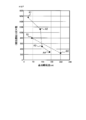
- FIG. 4 is a graph showing the relationship between the durability of the outer ring member 14 and the base oil kinematic viscosity of the lubricating oil when the lubricating oil is changed.
- the vertical axis represents the durability (number of rotations) of the outer ring member 14 and the horizontal axis. Is the base oil kinematic viscosity of the lubricating oil at a temperature of 40 ° C.
- the durability (number of rotations) of the outer ring member 14 on the vertical axis indicates the number of rotations of the outer ring member 14 that can maintain a usable state as the outer ring member 14.
- the black diamonds in FIG. 4 are data when linear fluorine grease is used as the base oil of the lubricating oil, and point A1 is the rotation when the base oil kinematic viscosity of the linear fluorine grease is 25 cst (40 ° C.).
- point A2 is the number of rotations when the base oil kinematic viscosity of the linear fluorine grease is 90 cst (40 ° C)
- point A3 is the number of rotations when the base oil kinematic viscosity of the linear fluorine grease is 100 cst (40 ° C)
- point A4 is the number of rotations when the base oil kinematic viscosity of the linear fluorine grease is 140 cst (40 ° C.).
- the base oil kinematic viscosity of the linear fluorine grease is 25 cst (40 ° C)
- the number of rotations of the outer ring member 14 is 15.5 million times (A1 point)
- the base oil kinematic viscosity of the linear fluorine grease is 90 cst (40 ° C)
- the number of rotations of the outer ring member 14 in this case is 11.28 million (A2 points)
- the number of rotations of the outer ring member 14 is 5 million times (A3 points) when the base oil kinematic viscosity of the linear fluorine grease is 100 cst (40 ° C.).
- the number of rotations of the outer ring member 14 is 3 million times (A4 point).
- the base oil kinematic viscosity of the mixed fluorine grease is 45 cst (40 ° C)
- the number of rotations of the outer ring member 14 is 8 million times (point B1)
- the base oil kinematic viscosity of the mixed fluorine grease is 200 cst (40 ° C)
- the number of rotations of the outer ring member 14 is 2.4 million (B2 point).
- linear fluorine grease and mixed fluorine grease In both cases of linear fluorine grease and mixed fluorine grease, the durability (number of rotations) of the outer ring member 14 improves as the base oil kinematic viscosity decreases. Further, when compared with the linear fluorine grease and the mixed fluorine grease, the durability (number of rotations) of the linear fluorine grease is improved. Therefore, it is preferable to use linear fluorine grease having a base oil kinematic viscosity of a predetermined value or less as the lubricating oil for the reverse input cutoff clutch of the present invention.
- linear fluorine grease having a base oil kinematic viscosity of 90 cst or less and more preferably a linear fluorine grease having a base oil kinematic viscosity of 25 cst (40 ° C.). .
Landscapes
- Engineering & Computer Science (AREA)
- General Engineering & Computer Science (AREA)
- Mechanical Engineering (AREA)
- Braking Arrangements (AREA)
- Mechanical Operated Clutches (AREA)
Abstract
Description
「回転力が入力される入力軸と、
回転力を出力する出力軸と、
前記入力軸に入力が与えられると前記出力軸にその入力の伝達を許可し、前記出力軸から逆入力が与えられると前記入力軸にその逆入力の伝達を阻止する伝達機構部と、
前記伝達機構部を収容する固定されたハウジング部材と、を備える逆入力遮断クラッチであって、
前記伝達機構部には、焼結部材で円筒状に成形され、前記ハウジングに回転可能に支持される外輪部材が設けられるとともに、前記外輪部材を取り巻いてその外周面に接触し、前記ハウジング部材に端部が係止されるコイルバネが設けられ、かつ、前記外輪部材の外周面には、表面粗さを小さくする表面加工が施されており、
前記伝達機構部は、前記出力軸からの逆入力の伝達を阻止している状態で、前記出力軸の逆入力と同方向の入力が前記出力軸に与えられたときは、その入力により、前記外輪部材を前記コイルバネの摩擦力に打ち勝って回転させて、前記出力軸を前記外輪部材と一体的に回転させる一方、前記出力軸の逆入力と逆方向の入力が前記入力軸に与えられたときは、その入力により、前記出力軸を前記入力軸から直接的に回転させる」
ことを特徴とする。
このように、この実施形態の逆入力遮断クラッチでは、出力軸12に下向きの負荷荷重による逆入力が作用しても、それのみではロック状態が解除しないため、負荷の断続的な下向き移動を防止できる。
また、外輪部材14の外面とコイルバネとの接触面に潤滑油として動粘度が所定値以下の直鎖系フッ素グリスを塗布することが好ましい。これらにより、外輪部材14とコイルバネ19との耐摩耗性を改善し、外輪部材14の耐久性を向上させるとともに、振動の発生を抑制して異常音の発生を抑制できるようになる。外輪部材14の表面加工やグリスの塗布の詳細については後述する。
Claims (4)
- 回転力が入力される入力軸と、
回転力を出力する出力軸と、
前記入力軸に入力が与えられると前記出力軸にその入力の伝達を許可し、前記出力軸から逆入力が与えられると前記入力軸にその逆入力の伝達を阻止する伝達機構部と、
前記伝達機構部を収容する固定されたハウジング部材と、を備える逆入力遮断クラッチであって、
前記伝達機構部には、焼結部材で円筒状に成形され、前記ハウジングに回転可能に支持される外輪部材が設けられるとともに、前記外輪部材を取り巻いてその外周面に接触し、前記ハウジング部材に端部が係止されるコイルバネが設けられ、かつ、前記外輪部材の外周面には、表面粗さを小さくする表面加工が施されており、
前記伝達機構部は、前記出力軸からの逆入力の伝達を阻止している状態で、前記出力軸の逆入力と同方向の入力が前記出力軸に与えられたときは、その入力により、前記外輪部材を前記コイルバネの摩擦力に打ち勝って回転させて、前記出力軸を前記外輪部材と一体的に回転させる一方、前記出力軸の逆入力と逆方向の入力が前記入力軸に与えられたときは、その入力により、前記出力軸を前記入力軸から直接的に回転させることを特徴とする逆入力遮断クラッチ。 - 表面粗さを小さくする前記表面加工は、ラップ加工である請求項1に記載の逆入力遮断クラッチ。
- 表面粗さを小さくする前記表面加工は、バレル加工である請求項1に記載の逆入力遮断クラッチ。
- 前記外輪部材の外周面と前記コイルバネとの接触面に、40℃における動粘度が90cst以下の直鎖系フッ素グリスが塗布されている請求項1乃至請求項3のいずれかに記載の逆入力遮断クラッチ。
Priority Applications (3)
| Application Number | Priority Date | Filing Date | Title |
|---|---|---|---|
| CN201580013322.2A CN106104053B (zh) | 2014-03-14 | 2015-03-05 | 反向输入阻断离合器 |
| JP2016507486A JP6157720B2 (ja) | 2014-03-14 | 2015-03-05 | 逆入力遮断クラッチ |
| KR1020167024189A KR102308397B1 (ko) | 2014-03-14 | 2015-03-05 | 역입력 차단 클러치 |
Applications Claiming Priority (2)
| Application Number | Priority Date | Filing Date | Title |
|---|---|---|---|
| JP2014052069 | 2014-03-14 | ||
| JP2014-052069 | 2014-03-14 |
Publications (1)
| Publication Number | Publication Date |
|---|---|
| WO2015137231A1 true WO2015137231A1 (ja) | 2015-09-17 |
Family
ID=54071677
Family Applications (1)
| Application Number | Title | Priority Date | Filing Date |
|---|---|---|---|
| PCT/JP2015/056495 Ceased WO2015137231A1 (ja) | 2014-03-14 | 2015-03-05 | 逆入力遮断クラッチ |
Country Status (5)
| Country | Link |
|---|---|
| JP (1) | JP6157720B2 (ja) |
| KR (1) | KR102308397B1 (ja) |
| CN (1) | CN106104053B (ja) |
| TW (1) | TWI666392B (ja) |
| WO (1) | WO2015137231A1 (ja) |
Cited By (2)
| Publication number | Priority date | Publication date | Assignee | Title |
|---|---|---|---|---|
| WO2019065981A1 (ja) * | 2017-09-28 | 2019-04-04 | 株式会社アドヴィックス | 車両ブレーキおよび摩擦係合部材の周面の加工方法 |
| WO2025023087A1 (ja) * | 2023-07-26 | 2025-01-30 | 株式会社オリジン | 逆入力遮断クラッチ及びこれを用いたトルクリミッタ |
Families Citing this family (2)
| Publication number | Priority date | Publication date | Assignee | Title |
|---|---|---|---|---|
| US11300166B2 (en) * | 2019-09-20 | 2022-04-12 | Nsk Ltd. | Reverse input blocking clutch |
| EP4008922B1 (en) * | 2019-09-20 | 2023-09-06 | NSK Ltd. | Reverse input cutoff clutch |
Citations (4)
| Publication number | Priority date | Publication date | Assignee | Title |
|---|---|---|---|---|
| JPH0246538B2 (ja) * | 1982-03-15 | 1990-10-16 | Toray Industries | |
| JP2002372069A (ja) * | 2001-06-18 | 2002-12-26 | Kyocera Corp | トルクリミッタ及び画像形成装置の用紙分離機構 |
| JP2003176831A (ja) * | 2001-10-04 | 2003-06-27 | Nsk Ltd | 転がり軸受 |
| JP2013142443A (ja) * | 2012-01-11 | 2013-07-22 | Origin Electric Co Ltd | 逆入力遮断クラッチ |
Family Cites Families (7)
| Publication number | Priority date | Publication date | Assignee | Title |
|---|---|---|---|---|
| JP2803933B2 (ja) * | 1991-12-05 | 1998-09-24 | 三田工業株式会社 | バネクラッチ構造 |
| US5966581A (en) * | 1996-08-30 | 1999-10-12 | Borg-Warner Automotive, Inc. | Method of forming by cold worked powdered metal forged parts |
| DE60215854T2 (de) * | 2001-03-08 | 2007-06-28 | Ntn Corp. | Rückwärtsfahrende Sperrkupplung |
| US7160351B2 (en) * | 2002-10-01 | 2007-01-09 | Pmg Ohio Corp. | Powder metal clutch races for one-way clutches and method of manufacture |
| JP5117115B2 (ja) * | 2007-06-13 | 2013-01-09 | Ntn株式会社 | 逆入力防止クラッチ |
| JP2009192005A (ja) * | 2008-02-15 | 2009-08-27 | Ntn Corp | 逆入力防止クラッチ |
| JP5469698B2 (ja) * | 2012-03-27 | 2014-04-16 | オリジン電気株式会社 | 逆入力遮断クラッチ |
-
2015
- 2015-03-05 JP JP2016507486A patent/JP6157720B2/ja active Active
- 2015-03-05 KR KR1020167024189A patent/KR102308397B1/ko active Active
- 2015-03-05 CN CN201580013322.2A patent/CN106104053B/zh active Active
- 2015-03-05 WO PCT/JP2015/056495 patent/WO2015137231A1/ja not_active Ceased
- 2015-03-10 TW TW104107476A patent/TWI666392B/zh active
Patent Citations (4)
| Publication number | Priority date | Publication date | Assignee | Title |
|---|---|---|---|---|
| JPH0246538B2 (ja) * | 1982-03-15 | 1990-10-16 | Toray Industries | |
| JP2002372069A (ja) * | 2001-06-18 | 2002-12-26 | Kyocera Corp | トルクリミッタ及び画像形成装置の用紙分離機構 |
| JP2003176831A (ja) * | 2001-10-04 | 2003-06-27 | Nsk Ltd | 転がり軸受 |
| JP2013142443A (ja) * | 2012-01-11 | 2013-07-22 | Origin Electric Co Ltd | 逆入力遮断クラッチ |
Cited By (3)
| Publication number | Priority date | Publication date | Assignee | Title |
|---|---|---|---|---|
| WO2019065981A1 (ja) * | 2017-09-28 | 2019-04-04 | 株式会社アドヴィックス | 車両ブレーキおよび摩擦係合部材の周面の加工方法 |
| WO2025023087A1 (ja) * | 2023-07-26 | 2025-01-30 | 株式会社オリジン | 逆入力遮断クラッチ及びこれを用いたトルクリミッタ |
| JP2025018022A (ja) * | 2023-07-26 | 2025-02-06 | 株式会社オリジン | トルクリミッタ |
Also Published As
| Publication number | Publication date |
|---|---|
| CN106104053A (zh) | 2016-11-09 |
| KR102308397B1 (ko) | 2021-10-05 |
| KR20160134660A (ko) | 2016-11-23 |
| TWI666392B (zh) | 2019-07-21 |
| CN106104053B (zh) | 2018-11-13 |
| TW201604435A (zh) | 2016-02-01 |
| JP6157720B2 (ja) | 2017-07-05 |
| JPWO2015137231A1 (ja) | 2017-04-06 |
Similar Documents
| Publication | Publication Date | Title |
|---|---|---|
| JP6157720B2 (ja) | 逆入力遮断クラッチ | |
| WO2015012053A1 (ja) | 一方向クラッチ内蔵型プーリ装置 | |
| US3628389A (en) | Infinitely variable speed belt transmission with conical pulleys | |
| JP5972483B2 (ja) | トルクリミッタ | |
| JP2010281375A (ja) | 逆入力遮断クラッチ | |
| JP2004308719A (ja) | ワンウェイクラッチ装置 | |
| JP5096232B2 (ja) | 逆入力防止クラッチ | |
| EP1403546A4 (en) | BUILT-IN FREEWHEET COUPLING IN ROTATION TRANSMISSION DEVICE | |
| JP2006057688A (ja) | 逆入力遮断装置 | |
| HK1226465B (zh) | 反向输入阻断离合器 | |
| JP2005016555A (ja) | ワンウェイクラッチ及びワンウェイクラッチの取付け構造 | |
| HK1226465A1 (en) | Reverse input blocking clutch | |
| JP2017214943A (ja) | 逆入力防止クラッチ | |
| JP6297355B2 (ja) | 逆入力防止クラッチ | |
| WO2017150404A1 (ja) | 逆入力遮断装置 | |
| JP2007016878A (ja) | 逆入力遮断クラッチ | |
| CN106062405B (zh) | 反向输入阻断离合器 | |
| JP2014206286A (ja) | 電動式ディスクブレーキ装置 | |
| JP2009192005A (ja) | 逆入力防止クラッチ | |
| US3099339A (en) | Uni-directional driving devices | |
| JP2007051664A (ja) | 逆入力遮断クラッチ | |
| JP2016053402A (ja) | ダンパプーリ | |
| JP2017122469A (ja) | ボールクラッチ及びこれを具えた減速機 | |
| JP2016166638A (ja) | 回転伝達装置 | |
| JP2015209956A (ja) | 歯車伝動装置 |
Legal Events
| Date | Code | Title | Description |
|---|---|---|---|
| 121 | Ep: the epo has been informed by wipo that ep was designated in this application |
Ref document number: 15762165 Country of ref document: EP Kind code of ref document: A1 |
|
| ENP | Entry into the national phase |
Ref document number: 2016507486 Country of ref document: JP Kind code of ref document: A |
|
| ENP | Entry into the national phase |
Ref document number: 20167024189 Country of ref document: KR Kind code of ref document: A |
|
| NENP | Non-entry into the national phase |
Ref country code: DE |
|
| 122 | Ep: pct application non-entry in european phase |
Ref document number: 15762165 Country of ref document: EP Kind code of ref document: A1 |