WO2015137308A1 - Module de membrane à fibres creuses et son procédé de fabrication - Google Patents
Module de membrane à fibres creuses et son procédé de fabrication Download PDFInfo
- Publication number
- WO2015137308A1 WO2015137308A1 PCT/JP2015/056939 JP2015056939W WO2015137308A1 WO 2015137308 A1 WO2015137308 A1 WO 2015137308A1 JP 2015056939 W JP2015056939 W JP 2015056939W WO 2015137308 A1 WO2015137308 A1 WO 2015137308A1
- Authority
- WO
- WIPO (PCT)
- Prior art keywords
- hollow fiber
- fiber membrane
- case
- membrane bundle
- bundle
- Prior art date
- Legal status (The legal status is an assumption and is not a legal conclusion. Google has not performed a legal analysis and makes no representation as to the accuracy of the status listed.)
- Ceased
Links
Images





Classifications
-
- B—PERFORMING OPERATIONS; TRANSPORTING
- B01—PHYSICAL OR CHEMICAL PROCESSES OR APPARATUS IN GENERAL
- B01D—SEPARATION
- B01D63/00—Apparatus in general for separation processes using semi-permeable membranes
- B01D63/02—Hollow fibre modules
- B01D63/04—Hollow fibre modules comprising multiple hollow fibre assemblies
-
- B—PERFORMING OPERATIONS; TRANSPORTING
- B01—PHYSICAL OR CHEMICAL PROCESSES OR APPARATUS IN GENERAL
- B01D—SEPARATION
- B01D63/00—Apparatus in general for separation processes using semi-permeable membranes
- B01D63/02—Hollow fibre modules
- B01D63/021—Manufacturing thereof
-
- B—PERFORMING OPERATIONS; TRANSPORTING
- B01—PHYSICAL OR CHEMICAL PROCESSES OR APPARATUS IN GENERAL
- B01D—SEPARATION
- B01D63/00—Apparatus in general for separation processes using semi-permeable membranes
- B01D63/02—Hollow fibre modules
- B01D63/024—Hollow fibre modules with a single potted end
- B01D63/0241—Hollow fibre modules with a single potted end being U-shaped
-
- B—PERFORMING OPERATIONS; TRANSPORTING
- B01—PHYSICAL OR CHEMICAL PROCESSES OR APPARATUS IN GENERAL
- B01D—SEPARATION
- B01D65/00—Accessories or auxiliary operations, in general, for separation processes or apparatus using semi-permeable membranes
- B01D65/003—Membrane bonding or sealing
-
- B—PERFORMING OPERATIONS; TRANSPORTING
- B01—PHYSICAL OR CHEMICAL PROCESSES OR APPARATUS IN GENERAL
- B01D—SEPARATION
- B01D69/00—Semi-permeable membranes for separation processes or apparatus characterised by their form, structure or properties; Manufacturing processes specially adapted therefor
- B01D69/08—Hollow fibre membranes
-
- C—CHEMISTRY; METALLURGY
- C02—TREATMENT OF WATER, WASTE WATER, SEWAGE, OR SLUDGE
- C02F—TREATMENT OF WATER, WASTE WATER, SEWAGE, OR SLUDGE
- C02F1/00—Treatment of water, waste water, or sewage
- C02F1/001—Processes for the treatment of water whereby the filtration technique is of importance
- C02F1/003—Processes for the treatment of water whereby the filtration technique is of importance using household-type filters for producing potable water, e.g. pitchers, bottles, faucet mounted devices
-
- B—PERFORMING OPERATIONS; TRANSPORTING
- B01—PHYSICAL OR CHEMICAL PROCESSES OR APPARATUS IN GENERAL
- B01D—SEPARATION
- B01D2313/00—Details relating to membrane modules or apparatus
- B01D2313/04—Specific sealing means
- B01D2313/042—Adhesives or glues
-
- B—PERFORMING OPERATIONS; TRANSPORTING
- B01—PHYSICAL OR CHEMICAL PROCESSES OR APPARATUS IN GENERAL
- B01D—SEPARATION
- B01D2313/00—Details relating to membrane modules or apparatus
- B01D2313/20—Specific housing
- B01D2313/205—Specific housing characterised by the shape
-
- C—CHEMISTRY; METALLURGY
- C02—TREATMENT OF WATER, WASTE WATER, SEWAGE, OR SLUDGE
- C02F—TREATMENT OF WATER, WASTE WATER, SEWAGE, OR SLUDGE
- C02F1/00—Treatment of water, waste water, or sewage
- C02F1/28—Treatment of water, waste water, or sewage by sorption
- C02F1/283—Treatment of water, waste water, or sewage by sorption using coal, charred products, or inorganic mixtures containing them
-
- C—CHEMISTRY; METALLURGY
- C02—TREATMENT OF WATER, WASTE WATER, SEWAGE, OR SLUDGE
- C02F—TREATMENT OF WATER, WASTE WATER, SEWAGE, OR SLUDGE
- C02F1/00—Treatment of water, waste water, or sewage
- C02F1/44—Treatment of water, waste water, or sewage by dialysis, osmosis or reverse osmosis
- C02F1/444—Treatment of water, waste water, or sewage by dialysis, osmosis or reverse osmosis by ultrafiltration or microfiltration
-
- C—CHEMISTRY; METALLURGY
- C02—TREATMENT OF WATER, WASTE WATER, SEWAGE, OR SLUDGE
- C02F—TREATMENT OF WATER, WASTE WATER, SEWAGE, OR SLUDGE
- C02F2201/00—Apparatus for treatment of water, waste water or sewage
- C02F2201/002—Construction details of the apparatus
- C02F2201/006—Cartridges
Definitions
- the present invention relates to a hollow fiber membrane module and a manufacturing method thereof.
- This application claims priority based on Japanese Patent Application No. 2014-046873 filed in Japan on March 10, 2014, the contents of which are incorporated herein by reference.
- water purifiers that purify tap water are generally used in homes and the like.
- Many such water purifiers are known that use a hollow fiber membrane module as a filter medium.
- a hollow fiber membrane module a hollow fiber membrane bundle formed by bending a large number of hollow fiber membranes is loaded into a cylindrical case, and a fixing resin is injected into the case, so that the hollow fiber membrane A device in which the side opposite to the bent portion of the bundle is fixed to the bottom of the case is known.
- the hollow fiber membrane bundle loaded and accommodated in the case is generally a hollow fiber membrane bent in a U shape.
- simply bending the hollow fiber membrane into a U-shape reduces the filling efficiency of the hollow fiber membrane and makes it difficult to improve the filtration performance, particularly when the hollow fiber membrane bundle is accommodated in a cylindrical case.
- the shape of the hollow fiber membrane bundle in plan view is substantially rectangular or oval, and is straight in plan view.
- a gap is formed between the portion and the inner surface of the case that is circular in plan view, and as a result, the filling efficiency is lowered.
- the filling efficiency is lowered in this way, it is difficult to reduce the size of the module because it is necessary to obtain a predetermined filtration performance.
- a hollow fiber membrane bundle is formed by bending a hollow fiber membrane into a U-shape, and the hollow fiber membrane bundle is twisted and accommodated in a case.
- the filling efficiency is increased.
- the hollow fiber membrane module of patent document 2 the hollow fiber membrane bundle which bent the hollow fiber membrane in the U-shape is divided
- a bundle of many hollow fiber membranes is bent and twisted and stored in a case.
- JP-A-6-142650 Japanese Utility Model Publication No. 7-24430 Japanese Patent Laid-Open No. 7-213872
- the hollow fiber membrane module is formed by twisting the hollow fiber membrane bundle as in Patent Document 1 and Patent Document 3, the hollow fiber membranes are in close contact with each other at the twisted portion. It is not utilized, and therefore the filtration performance has not reached a sufficiently high level. In addition, the gap generated between the hollow fiber membrane bundle described above and the inner surface of the case remains without being eliminated.
- a fixing resin is injected into the case and the side opposite to the bent portion of the hollow fiber membrane bundle is fixed to the bottom of the case.
- the hollow fiber membrane bundle can be fixed to the bottom of the case and the sealing between the hollow fiber membranes can be uneven. Therefore, in order to securely fix and seal the bottom of the hollow fiber membrane bundle, Needs to be sufficiently thick (high). However, if the layer height of the fixing resin is made sufficiently thick in this way, downsizing of the hollow fiber membrane module is prevented accordingly.
- the present invention has been made in view of the above circumstances, and provides a hollow fiber membrane module that improves the filtration performance by increasing the filling efficiency of the hollow fiber membrane into the case, and that can be miniaturized, and a method for manufacturing the same. With the goal.
- a hollow fiber membrane module according to the present invention has a hollow fiber membrane bundle in which a large number of hollow fiber membranes are bent in a U-shape and is loaded in a cylindrical case, and is fixed in the case.
- a hollow fiber membrane module in which resin is injected and the side opposite to the bent portion of the hollow fiber membrane bundle is fixed to the bottom of the case, the hollow fiber membrane being bent in a U shape in the case,
- a void portion is formed at a substantially central portion of the hollow fiber membrane bundle along the height direction of the case, and a core rod is inserted through the void portion.
- the hollow fiber membrane is bent in a U-shape in the case, and for example, formed so that the bending direction of the hollow fiber membrane faces a different direction without being aligned in a certain direction. Therefore, the planar shape can be formed in accordance with the planar shape of the case, and therefore the filling efficiency of the hollow fiber membrane into the case can be increased. Further, since a void is formed in the substantially central portion of the hollow fiber membrane bundle along the height direction of the case, and the core rod is inserted into the void, water easily flows into the void. Thereby, since water becomes easy to flow into the center part of a hollow fiber membrane bundle, the filtration flow rate increases and it becomes possible to filter water in a shorter time. In addition, since water easily flows into the center portion of the hollow fiber membrane bundle, it is possible to filter water while using the membrane area of the hollow fiber membrane more effectively.
- the hollow fiber membrane bundle is bent in a U shape from a central portion of the case toward an inner wall portion.
- the hollow fiber membranes are arranged radially from the center of the case. According to this structure, it becomes easy to form the said space
- the core rod is preferably the tube for injecting the fixing resin.
- the fixing resin is injected through the tube.
- the fixing resin can be uniformly injected and filled in the bottom of the case.
- the case is preferably cylindrical. According to this configuration, the hollow fiber membrane bundle can be loaded with almost no gap between the hollow fiber membrane bundle and the inner wall surface of the case by making the shape of the hollow fiber membrane bundle in a plan view circular.
- the said hollow fiber membrane module WHEREIN may be formed by the small bundle divided
- the method for producing a hollow fiber membrane module according to the present invention is to load a hollow fiber membrane bundle in which a number of hollow fiber membranes are bent into a U shape into a cylindrical case, and inject a fixing resin into the case.
- a hollow fiber membrane bundle by bending it into a U-shape, providing a tube in the gap, and heat-cutting the opposite side of the hollow fiber membrane bundle to form a bottom portion Loading the hollow fiber membrane bundle having the bottom surface portion into a cylindrical case; injecting a fixing resin into the bottom side of the case through the tube; Fixing the bottom of the case to the bottom of the case Was cut by cutting the bottom portion side of the hollow fiber membrane bundle comprises the steps of exposing open ends of the hollow fiber membrane bundle, the.
- the hollow fiber membrane bundle is formed into a U shape by bending the hollow fiber membrane bundle by the above method, so that the bending direction is not aligned in a certain direction. Since it can be formed so as to face in different directions, its planar shape can be formed in accordance with the planar shape of the case, and therefore the efficiency of filling the hollow fiber membrane into the case can be increased.
- a hollow portion is formed in the substantially central portion of the hollow fiber membrane bundle, and a tube is provided in the hollow portion, and a fixing resin is injected into the bottom side of the case through the tube so that the bottom portion side of the hollow fiber membrane bundle is Since it is fixed to the bottom of the case, the fixing resin can be uniformly injected and filled into the bottom of the case.
- the hollow fiber membrane module in the step of forming the hollow fiber membrane bundle, a large number of hollow fiber membranes are bent in a U shape from the center side toward the outside with the core rod as the center. At the same time, it is preferable that the hollow fiber membranes are radially arranged around the core rod and converged to form a hollow fiber membrane bundle. According to this configuration, it is easy to form the void portion at the substantially central portion of the hollow fiber membrane bundle by the core rod, and the shape of the hollow fiber membrane bundle in plan view can be easily made circular.
- the step of forming the hollow fiber membrane bundle can also serve as the step of providing the tube in the gap, and thus the process can be simplified.
- the tube in the step of providing the tube in the gap, it is preferable that the tube is inserted into the formed gap after removing the core rod from the hollow fiber membrane bundle.
- an appropriate material capable of forming a desired void can be used as the core rod, and therefore, the step of forming the hollow fiber membrane bundle can be simplified.
- the case is preferably cylindrical. According to this configuration, the hollow fiber membrane bundle can be loaded with almost no gap between the hollow fiber membrane bundle and the inner wall surface of the case by making the shape of the hollow fiber membrane bundle in a plan view circular.
- the hollow fiber membrane bundle in the step of forming the hollow fiber membrane bundle, is formed by a small bundle divided into a plurality in a circumferential direction centering on the gap portion. It is preferable to do. According to this configuration, the membrane area can be increased by forming the hollow fiber membrane bundle with small bundles. Moreover, it becomes easy to form the said space
- the filling efficiency of the hollow fiber membrane into the case can be increased by forming the hollow fiber membrane bundle according to the planar shape of the case, thereby increasing the efficiency of filling the hollow fiber membrane into the case.
- the filtration performance can be improved.
- the core rod is inserted into the gap formed along the height direction of the case at the substantially central portion of the hollow fiber membrane bundle, water can easily flow into the central portion of the hollow fiber membrane bundle.
- the filtration flow rate increases, and it becomes possible to filter water in a shorter time, and it is possible to filter water while making more effective use of the membrane area of the hollow fiber membrane.
- the fixing resin when a tube is employed as the core rod, the fixing resin can be uniformly injected and filled into the bottom of the case by injecting the fixing resin through the tube. Therefore, the layer height of the fixing resin can be made relatively thin (low), and thereby the hollow fiber membrane module can be miniaturized.
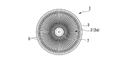
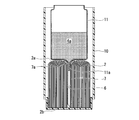
- FIG. 1A and 1B It is a sectional side view showing a schematic structure of one embodiment of a hollow fiber membrane module concerning the present invention. It is a top view which shows schematic structure of one Embodiment of the hollow fiber membrane module which concerns on this invention. It is a perspective view which shows schematic structure of the hollow fiber membrane bundle used for the hollow fiber membrane module shown to FIG. 1A and 1B. It is a top view which shows schematic structure of the hollow fiber membrane bundle used for the hollow fiber membrane module shown to FIG. 1A and 1B. It is a figure for demonstrating the heat cutting process of a hollow fiber membrane bundle. It is a figure for demonstrating the loading process in the case of a hollow fiber membrane bundle. It is a figure for demonstrating the injection process of resin for fixing.
- FIGS. 1A and 1B are diagrams showing a schematic configuration of an embodiment of a hollow fiber membrane module according to the present invention
- FIG. 1A is a side sectional view
- FIG. 1B is a plan view
- 2A and 2B are diagrams showing a schematic configuration of a hollow fiber membrane bundle used in the hollow fiber membrane module shown in FIGS. 1A and 1B.
- FIG. 2A is a perspective view
- FIG. 2B is a plan view. It is.
- reference numeral 1 denotes a hollow fiber membrane module.
- a hollow fiber membrane bundle 2 is loaded in a cylindrical case 3, and the case 3 is fixed by a fixing resin 4. It is fixed to the bottom.
- the hollow fiber membrane bundle 2 is formed in a substantially cylindrical shape (substantially cylindrical shape) by bending a large number of hollow fiber membranes 5 into a U shape as shown in FIGS. 2A and 2B. . That is, in the example described in the present embodiment, a large number of hollow fiber membranes 5 are bent in a U shape from the center (center) of the case 3 toward the inner wall as shown in FIGS. 1A and 2B. At the same time, the hollow fiber membrane 5 is arranged radially from the center of the case 3 so that it is formed in a substantially columnar shape (substantially cylindrical shape).
- a hollow portion 6 is formed in the substantially central portion of the hollow fiber membrane bundle 2 along the central axis direction, and a center tube (tube) that functions as a core rod is formed in the void portion 6. 7 is inserted.
- a core rod not only a tube-shaped thing but a solid core rod can also be used.
- the hollow fiber membrane 5 constituting the hollow fiber membrane bundle 2 include various materials such as cellulose, polyolefin (polyethylene), polyvinyl alcohol, PMMA (polymethyl methacrylate), and polysulfone. Things are used.
- a polysulfone-based hollow fiber membrane is suitably used as the hollow fiber membrane 5 because it is particularly excellent in water permeability and easy to manufacture.
- the polyethylene-based hollow fiber membrane has a particularly high strength and elongation, for example, when bending into a U shape, the bending radius r can be reduced to increase the curvature, which is particularly effective when it is desired to increase the curvature. It is.
- the hollow fiber membrane 5 is bent in a U shape from the central portion of the case 3 toward the inner wall portion, and therefore the curvature is relatively small (the bending radius r is relatively small). Therefore, a polysulfone-based hollow fiber membrane 5 excellent in water permeability and the like is used.
- Such a hollow fiber membrane 5 is fixed on the bottom side of the case 3 with the fixing resin 4 as described above. That is, the space between the hollow fiber membranes 5 is sealed with the fixing resin 4, and the hollow fiber membranes 5 are liquid-tightly fixed to the inner wall surface of the bottom portion of the case 3.
- the hollow fiber membrane 5 is opened on the bottom side of the case 3 in the state of being fixed by the fixing resin 4 as described above, and thus the opened end surface is exposed to the outside of the case 3.
- the bent portion 2 a of the hollow fiber membrane bundle 2 formed by bending the hollow fiber membrane 5 into a U shape is arranged facing the side opposite to the bottom portion of the case 3.
- the bent portion 2 a is disposed at a substantially central portion in the height direction of the case 3.
- the hole diameter, porosity, film thickness, outer diameter, and the like of the hollow fiber membrane 5 forming the hollow fiber membrane bundle 2 are not particularly limited as long as the hollow fiber membrane 5 can be used as a filtration membrane.
- the diameter is preferably about 20 to 4000 ⁇ m
- the pore diameter is about 0.01 to 1 ⁇ m
- the porosity is about 20 to 90%
- the film thickness is preferably about 5 to 300 ⁇ m.
- the case 3 may be made of any material having mechanical strength and durability.
- polycarbonate polysulfone, polyolefin, PVC (polyvinyl chloride), acrylic resin, ABS resin, modified PPE (polyphenylene ether), etc. Is used.
- the fixing resin an epoxy resin, an unsaturated polyester resin, a polyurethane resin, a silicone-based filler, various hot melt resins, and the like can be used, and these are appropriately selected and used.
- the center tube 7 is a tubular member, and an annular flange portion 7 a is formed on one end side, that is, on the bent portion 2 a side of the hollow fiber membrane bundle 2.
- the length of the center tube 7 is formed substantially equal to the height of the hollow fiber membrane bundle 2.
- the surface on the other end side of the center tube 7, that is, the surface opposite to the flange portion 7a is an open end. In this way, the surface on the other end only needs to be open.
- the center tube 7 also functions as a core rod that is inserted into the gap portion 6 formed in the hollow fiber membrane bundle 2.
- a core rod such as a tube 7 is inserted into the gap 6 formed at the substantially central portion of the hollow fiber membrane bundle 2 as described above.
- water easily flows into the center of the hollow fiber membrane bundle 2.
- the filtration flow rate in the hollow fiber membrane bundle 2 increases, it becomes possible to filter water in a shorter time, and water is filtered while using the membrane area of the hollow fiber membrane 5 more effectively. Is possible.
- the hollow fiber membrane module 1 having such a configuration will be described with reference to the same drawings as described above.
- a large number of hollow fiber membranes 5 are bundled and bent into a U-shape so that a gap 6 is formed at a substantially central portion of the bundled hollow fiber membranes.
- the hollow fiber membrane bundle 2 is formed such that the bending direction of the hollow fiber membranes 5 is not aligned in a certain direction while being bent in a U-shape. Is more preferable.
- the void 6 is formed at the center of a hollow fiber membrane in which core rods (not shown) are bundled, and the hollow fiber membrane 5 is bent in a U shape from the center side to the outside.
- the hollow fiber membranes 5 are radially arranged around the core rod and converged to form the hollow fiber membrane bundle 2.
- the hollow fiber membrane 5 When the hollow fiber membrane 5 is bent into a U-shape, for example, a large number of hollow fiber membranes 5 bundled around the core rod are inserted into a cylindrical body with one end thereof open at the upper end together with the core rod. , Hold and fix. Subsequently, the other end of the hollow fiber membrane 5 is bent into a U shape. At that time, for example, a large number of hollow fiber membranes 5 are divided into four parts, bent from the center side (core bar side) to the outside, and along the outer surface of the cylindrical body. As a result, the hollow fiber membrane 5 divided into four can be bent substantially in four directions.
- the hollow fiber membranes 5 divided into four parts and bent toward the four sides are brought closer to each other, and a large number of hollow fiber membranes 5 are oriented almost uniformly in all directions (360 °) around the core rod. Adjust and arrange radially. Thereby, the bending part 2a of the hollow fiber membrane bundle 2 is formed. Thereafter, a large number of hollow fiber membranes 5 are extracted from the cylindrical body to form a hollow fiber membrane bundle 2.
- the core rod is removed, and the center tube 7 is inserted into the formed gap 6.
- the hollow fiber membrane bundle 2 can be produced using the center tube 7 as a core rod.
- the side opposite to the bent portion 2a of the hollow fiber membrane bundle 2 is heated and cut to form a bottom surface portion.
- the hollow fiber membrane bundle 2 is accommodated in the accommodation hole 8a of the mold 8 in which the opening surface is formed with a circular accommodation hole 8a, and the side opposite to the bent portion 2a is accommodated.
- An appropriate amount protrudes from the hole 8a, and in this state, the protruding portion of the hollow fiber membrane bundle 2 is heated and cut by the heat cutter 9. That is, the protruding portion of the hollow fiber membrane bundle 2 is heated and cut in a melted state.
- hollow fiber membranes 5 glass fiber membrane bundles 2
- a flat bottom surface portion 2b can be formed on the side opposite to the bent portions 2a of the hollow fiber membrane bundles 2.
- many hollow fiber membranes 5 form the melt
- the center tube 7 is moved to the bent portion 2a side of the hollow fiber membrane bundle 2 so as not to cut the center tube 7, and is protruded from the bent portion 2a side. Keep it.
- the removal of the core rod from the hollow fiber membrane bundle 2 and the insertion of the center tube 7 into the gap 6 are performed before the heat cutting of the hollow fiber membrane bundle 2, You may make it carry out after the heat cutting of the hollow fiber membrane bundle 2.
- the core bar is moved to the bent portion 2a side during the heat cutting so that the core bar does not interfere with the heat cutting of the hollow fiber membrane bundle 2.
- the hollow fiber membrane bundle 2 having the bottom surface portion 2 b is loaded into a bottomed cylindrical case 10.
- the bottom surface portion 2b is directed to the bottom surface side of the case 10 and loaded to the back (bottom) of the case 10, and the bottom surface portion 2b is brought into contact with the bottom surface (inner surface) of the case 10.
- the center tube 7 that has been moved to the bent portion 2a side of the hollow fiber membrane bundle 2 before or after the hollow fiber membrane bundle 2 is loaded into the case 10 is pushed into the bottom surface portion 2b side (movement). )
- the tip of the center tube 7 may be in contact with the bottom.
- the center tube 7 may be arranged so as to be located on the bent portion 2a side, for example, about 2 to 10 mm from the surface of the bottom surface portion 2b.
- the resin pot 11 is loaded into the case 10, and the discharge pipe 11 a is inserted into the flange portion 7 a of the center tube 7. Subsequently, the resin pot 11 is filled with a fixing resin 4a that is liquid before curing.
- the viscosity of the fixing resin 4a which has been liquefied before curing is not particularly limited, but is preferably in the range of 300 to 5000 mPa ⁇ s, more preferably 500 to 3000 mPa ⁇ s. If the viscosity of the liquid fixing resin 4a is less than 300 mPa ⁇ s, the fixing resin 4a may flow to the opening end of the hollow fiber membrane 5 and block the inside of the opening end. On the other hand, when the viscosity of the fixing resin 4a exceeds 5000 mPa ⁇ s, good impregnation between the hollow fiber membranes 5 tends to be difficult, which is not preferable.
- the case 10 is rotated by a centrifuge so that the bottom side of the case 10 is on the outside and the bent part 2a side of the hollow fiber membrane bundle 2 is on the inside, and centrifugal force is applied.
- the liquid fixing resin 4 a in the resin pot 11 reaches the bottom side of the case 10 through the discharge pipe 11 a and the center tube 7. That is, the fixing resin 4 a is guided to the center tube 7 and injected into the bottom side of the case 10. Accordingly, the injected fixing resin 4a gradually rises from the bottom side of the case 10 to the bent portion 2a side of the hollow fiber membrane bundle 2, so that the case 10 and the hollow fiber membrane bundle 2 are each in between.
- the hollow fiber membranes 5 are filled evenly.
- the resin pot 11 is removed, and the fixing resin 4 a filled in the case 10 is cured to fix the bottom surface 2 b side of the hollow fiber membrane bundle 2 to the bottom of the case 10.
- the bottom side of the case 10 is cut, and the bottom surface 2b side of the hollow fiber membrane bundle 2 is cut.
- the cut surface of each hollow fiber membrane 5 is formed in the said bottom face part 2b side of the hollow fiber membrane bundle 2, ie, a cutting
- the open ends of the hollow fiber membranes 5 are exposed, so that the open ends of the hollow fiber membrane bundles 2 are also exposed on the bottom side of the case 3 (10) whose bottom is open.
- the hollow fiber membrane module 1 shown to FIG. 1A and FIG. 1B is obtained.
- the hollow fiber membrane bundle 2 is formed so as to face different directions without being aligned in a constant direction.
- the membrane bundle 2 is bent in a U shape from the center side toward the outside with the core rod as the center.
- the hollow fiber membrane bundle 2 can be formed by radially arranging and concentrating the hollow fiber membrane bundle 2 around the core rod.
- the planar shape of the hollow fiber membrane bundle 2 can be easily formed in accordance with the planar shape of the case 3. That is, the hollow fiber membrane bundle 2 can be formed in a substantially columnar shape (substantially cylindrical shape) circular in plan view with respect to the case 3 having a circular shape in plan view.
- the hollow fiber membrane bundle 2 can be loaded in the case 3 without any gap, and thereby the efficiency of filling the hollow fiber membrane 5 into the case 3 is improved. Can be increased. Therefore, the filtration performance of the hollow fiber membrane module 1 can be improved.
- a gap 6 is formed at substantially the center of the hollow fiber membrane bundle 2
- a center tube 7 is provided in the gap 6, and a liquid fixing resin 4 a is injected into the bottom of the case 10 through the center tube 7. Since the bottom surface 2b side of the hollow fiber membrane bundle 2 is fixed to the bottom of the case 10, the fixing resin 4a can be uniformly injected and filled into the bottom of the case 10. Accordingly, there is no unevenness in fixing the hollow fiber membrane bundle 2 to the bottom of the case 10 and sealing between the hollow fiber membranes 5, so that the layer height of the fixing resin 4 (4a) is made relatively thin (low). However, the bottom part of the hollow fiber membrane bundle 2 can be reliably fixed and sealed. Therefore, the hollow fiber membrane module 1 obtained can be reduced in size.
- the hollow fiber membrane bundle 2 is formed so that the planar shape of the hollow fiber membrane bundle 2 matches the planar shape of the case 3. 5 filling efficiency is increased, thus improving the filtration performance. Further, by injecting the fixing resin 4a through the center tube 7, the fixing resin 4a (4) is uniformly injected and filled in the bottom portion of the case 10 (3), so that the layer height of the fixing resin is relatively increased. Can be thin (lower). Therefore, the hollow fiber membrane module 1 can be downsized.
- the technical scope of the present invention is not limited to the above embodiment, and various modifications can be made without departing from the spirit of the present invention.
- a method using a core rod to form the gap portion 6 is described.
- the tube 7 may be used.
- the step (step) of forming the hollow fiber membrane bundle 2 can also serve as the step (step) of providing the center tube 7 in the gap 6, and therefore the process Can be simplified.
- the hollow fiber membrane bundle 2 is formed as one large bundle.
- the present invention is not limited to this.
- FIG. As such a small bundle 12a, for example, as in the example shown in FIG. 6, the hollow fiber membrane 5 constituting this may be bent in a U shape and aligned in the same direction, or Similar to the hollow fiber membrane bundle 2, they may be arranged radially.
- the hollow fiber membrane 5 constituting this is formed so that the bending direction of the hollow fiber membrane 5 faces different directions without being aligned in a certain direction. That is, the hollow fiber membrane bundle 12 is placed in the case 3 so that the directions of the small bundles 12a are different from each other.
- the membrane area of the hollow fiber membrane bundle 12 can be increased, and thus the filtration performance can be improved.
- the case for loading the hollow fiber membrane bundle is not limited to the cylindrical shape as shown in the figure, and for example, various cylindrical shapes such as a long cylindrical shape, an elliptical cylindrical shape, and a rectangular cylindrical shape are used. be able to.
- the above-mentioned hollow fiber membrane module 1 can be made into the cartridge for water purifiers by filling the case 3 with activated carbon, for example. That is, the hollow fiber membrane module 1 which concerns on this invention becomes a member used suitably for manufacture of the cartridge for water purifiers (for example, refer the pot type water purifier 100 shown in FIG. 7).
- a plurality of hollow fiber membranes 5 made of polysulfone having a yarn length (membrane width) of 65 mm (effective yarn length: 51 mm; potting length: 8 mm, cut length: 6 mm) are arranged on one end side thereof.
- the hollow fiber membrane 5 is bent in a U-shape from the central portion of the cylindrical body toward the inner wall portion so that a gap portion 6 is formed in the central portion, and is substantially cylindrical so as to be radial from the central portion.
- a hollow fiber membrane bundle 2 as shown in FIGS. 1A and 1B was formed.
- the center tube 7 was inserted into the gap 6 formed by removing the core rod from the radial center of the hollow fiber membrane bundle 2 formed in a cylindrical shape.
- the side opposite to the bent portion 2a of the hollow fiber membrane bundle 2 is heated and cut to form a bottom surface portion, and then the hollow fiber membrane bundle 2 with the center tube 7 inserted is formed into a cylindrical shape having an inner diameter of 40 mm.
- Inserted into case 30 As shown in FIG. 7, an O-ring 34 for fixing the case 30 to a container 101 constituting a pot-type water purifier described later is attached to the upper side surface of the body portion 31 in the cylindrical axis direction.
- the case 30 is provided with a bottom cover 32 whose tip is a small-diameter discharge port 32 a on the bottom surface side of the body portion 31, and at a position above the O-ring 34 in the body portion 31.
- the case 3 is different from the case 3 shown in FIG. 1A and FIG. 1B in that an upper lid 33 having a plurality of holes 33a for taking in raw water to be treated is provided. Then, by injecting liquid fixing resin 4 a from the flange portion 7 a of the center tube 7, the bottom surface portion of the hollow fiber membrane bundle 2 was fixed to the bottom surface portion of the case 30 by curing the fixing resin 4 a. By such a process, a hollow fiber membrane module 1A as shown in FIG.
- the specifications of the hollow fiber membrane module 1A were such that the filling rate of the hollow fiber membrane 5 in the case 30 was 49.1%, and the effective membrane area excluding the resin potting portion was 0.207 m 2 .
- the hollow fiber membrane module 1A obtained in the above-described step (step) is filled with 25 g of 20-40 mesh granular activated carbon 110 to produce a water purifier cartridge A, which is used as the sample of the example. (See FIG. 7).
- the cartridge for the water purifier of the above example except that the center tube (core bar) is not inserted into the gap 6 of the hollow fiber membrane bundle 2
- a water purifier cartridge B having the same specifications as A was prepared.
- the water purifier cartridge A which is an example, was produced by a method including a step of injecting the liquid fixing resin 4a from the center tube 7, whereas the water purifier cartridge B was produced. A method of opening a small hole in the side surface near the bottom of the case 3 and injecting the fixing resin 4a into the inside from the small hole was adopted.
- the O-ring 34 provided in the upper part of the cartridge A for water purifiers or the cartridge B for water purifiers is used as a sealing member, and by attaching to the bottom part of the raw water storage part 102, the raw water stored in the raw water storage part 102 is each It flowed into the cartridges A and B for water purifiers, and the treated water was configured to flow into the purified water storage unit 103.
- the cartridge B for water purifiers of a comparative example is equivalent to the following specifications of the hollow fiber membrane module A except that the center tube is not provided.
- 1 L of raw water is put into the raw water storage unit 102, and this raw water flows into each of the water purifier cartridges A and B by its own weight and then flows out into the purified water storage unit 103, so that the raw water in the raw water storage unit 102 is
- the filtration rate (initial filtration flow rate) was measured by measuring the time until it was completely eliminated. At this time, the filtration rate was measured by a method and conditions based on JIS S3201 (Japanese Industrial Standards: 2010 edition).
- the water purifier cartridge A of the example had a filtration rate of 0.26 L / min, while the water purifier cartridge B of the comparative example had a filtration rate of 0.18 L / min. min. That is, the water purifier cartridge A of the example required about 4 minutes to filter 1 L of raw water, whereas the water purifier cartridge B of the comparative example 5 required 5 to filter 1 L of raw water. It takes more than 30 minutes. From this, it is clear that the filtration rate of raw water can be significantly improved by providing the hollow fiber membrane module 1A having the configuration according to the present invention.
- the reason why the above-described effect can be obtained by the hollow fiber membrane module according to the present invention is that when raw water flows into the water purifier cartridge A (hollow fiber membrane module) from the raw water reservoir 102 by its own weight, the hollow fiber membrane bundle 2 It is conceivable that the core 6 (center tube 7) inserted into the gap 6 is expanded and the action of facilitating the flow of raw water is obtained.
Landscapes
- Chemical & Material Sciences (AREA)
- Chemical Kinetics & Catalysis (AREA)
- Engineering & Computer Science (AREA)
- Life Sciences & Earth Sciences (AREA)
- Hydrology & Water Resources (AREA)
- Environmental & Geological Engineering (AREA)
- Water Supply & Treatment (AREA)
- Organic Chemistry (AREA)
- Manufacturing & Machinery (AREA)
- Separation Using Semi-Permeable Membranes (AREA)
Abstract
Priority Applications (3)
| Application Number | Priority Date | Filing Date | Title |
|---|---|---|---|
| CN201580024381.XA CN106457156A (zh) | 2014-03-10 | 2015-03-10 | 中空纤维膜组件及其制造方法 |
| JP2015515331A JP6079871B2 (ja) | 2014-03-10 | 2015-03-10 | 中空糸膜モジュールとその製造方法 |
| KR1020167027957A KR20160130311A (ko) | 2014-03-10 | 2015-03-10 | 중공사막 모듈과 그 제조 방법 |
Applications Claiming Priority (2)
| Application Number | Priority Date | Filing Date | Title |
|---|---|---|---|
| JP2014046873 | 2014-03-10 | ||
| JP2014-046873 | 2014-03-10 |
Publications (1)
| Publication Number | Publication Date |
|---|---|
| WO2015137308A1 true WO2015137308A1 (fr) | 2015-09-17 |
Family
ID=54071752
Family Applications (1)
| Application Number | Title | Priority Date | Filing Date |
|---|---|---|---|
| PCT/JP2015/056939 Ceased WO2015137308A1 (fr) | 2014-03-10 | 2015-03-10 | Module de membrane à fibres creuses et son procédé de fabrication |
Country Status (5)
| Country | Link |
|---|---|
| JP (1) | JP6079871B2 (fr) |
| KR (1) | KR20160130311A (fr) |
| CN (1) | CN106457156A (fr) |
| TW (1) | TWI554327B (fr) |
| WO (1) | WO2015137308A1 (fr) |
Cited By (1)
| Publication number | Priority date | Publication date | Assignee | Title |
|---|---|---|---|---|
| WO2018230631A1 (fr) * | 2017-06-14 | 2018-12-20 | 三菱ケミカル・クリンスイ株式会社 | Module à membranes à fibres creuses du type à circulation externe |
Families Citing this family (2)
| Publication number | Priority date | Publication date | Assignee | Title |
|---|---|---|---|---|
| CN211886283U (zh) * | 2019-08-02 | 2020-11-10 | 珠海格力电器股份有限公司 | 一种用于卷式膜的中心管、卷式膜组件和净水系统 |
| CN113274886B (zh) * | 2021-06-03 | 2025-01-28 | 江西金达莱环保股份有限公司 | 膜组件清洗装置 |
Citations (6)
| Publication number | Priority date | Publication date | Assignee | Title |
|---|---|---|---|---|
| JPH0433928U (fr) * | 1990-07-12 | 1992-03-19 | ||
| JPH04171029A (ja) * | 1990-11-05 | 1992-06-18 | Daicel Chem Ind Ltd | 中空糸束の処理方法 |
| JPH04284834A (ja) * | 1991-03-14 | 1992-10-09 | Mitsubishi Rayon Co Ltd | 中空糸膜モジュールの製造方法 |
| JPH09122455A (ja) * | 1995-11-07 | 1997-05-13 | Nitto Denko Corp | 中空糸膜モジュールおよびその製造方法 |
| JP2013158690A (ja) * | 2012-02-03 | 2013-08-19 | Mitsubishi Rayon Cleansui Co Ltd | 円筒状ケーシング収納用の治具 |
| JP2013158689A (ja) * | 2012-02-03 | 2013-08-19 | Mitsubishi Rayon Cleansui Co Ltd | 中空糸膜モジュールの製造方法 |
Family Cites Families (5)
| Publication number | Priority date | Publication date | Assignee | Title |
|---|---|---|---|---|
| JP2757722B2 (ja) | 1992-11-09 | 1998-05-25 | 東レ株式会社 | 浄水器用カートリッジ及びこれを備えた浄水器 |
| JPH0724430A (ja) | 1993-07-06 | 1995-01-27 | Japan Tobacco Inc | 円筒フィルタ洗浄装置 |
| JPH07213872A (ja) | 1994-02-07 | 1995-08-15 | Nok Corp | 中空糸膜モジュール |
| JP2010115613A (ja) * | 2008-11-14 | 2010-05-27 | Panasonic Electric Works Co Ltd | 浄水カートリッジ及び浄水器 |
| US8540081B2 (en) * | 2011-03-16 | 2013-09-24 | Markel Corporation | Fluoropolymer hollow fiber membrane with fluoro-copolymer and fluoro-terpolymer bonded end portion(s) and method to fabricate |
-
2015
- 2015-03-10 JP JP2015515331A patent/JP6079871B2/ja not_active Expired - Fee Related
- 2015-03-10 TW TW104107593A patent/TWI554327B/zh not_active IP Right Cessation
- 2015-03-10 WO PCT/JP2015/056939 patent/WO2015137308A1/fr not_active Ceased
- 2015-03-10 CN CN201580024381.XA patent/CN106457156A/zh not_active Withdrawn
- 2015-03-10 KR KR1020167027957A patent/KR20160130311A/ko not_active Ceased
Patent Citations (6)
| Publication number | Priority date | Publication date | Assignee | Title |
|---|---|---|---|---|
| JPH0433928U (fr) * | 1990-07-12 | 1992-03-19 | ||
| JPH04171029A (ja) * | 1990-11-05 | 1992-06-18 | Daicel Chem Ind Ltd | 中空糸束の処理方法 |
| JPH04284834A (ja) * | 1991-03-14 | 1992-10-09 | Mitsubishi Rayon Co Ltd | 中空糸膜モジュールの製造方法 |
| JPH09122455A (ja) * | 1995-11-07 | 1997-05-13 | Nitto Denko Corp | 中空糸膜モジュールおよびその製造方法 |
| JP2013158690A (ja) * | 2012-02-03 | 2013-08-19 | Mitsubishi Rayon Cleansui Co Ltd | 円筒状ケーシング収納用の治具 |
| JP2013158689A (ja) * | 2012-02-03 | 2013-08-19 | Mitsubishi Rayon Cleansui Co Ltd | 中空糸膜モジュールの製造方法 |
Cited By (5)
| Publication number | Priority date | Publication date | Assignee | Title |
|---|---|---|---|---|
| WO2018230631A1 (fr) * | 2017-06-14 | 2018-12-20 | 三菱ケミカル・クリンスイ株式会社 | Module à membranes à fibres creuses du type à circulation externe |
| JPWO2018230631A1 (ja) * | 2017-06-14 | 2019-06-27 | 三菱ケミカル・クリンスイ株式会社 | 外部潅流型中空糸膜モジュール |
| KR20200010431A (ko) * | 2017-06-14 | 2020-01-30 | 미츠비시 케미카루 크린스이 가부시키가이샤 | 외부 관류형 중공사막 모듈 |
| KR102323004B1 (ko) * | 2017-06-14 | 2021-11-05 | 미츠비시 케미카루 크린스이 가부시키가이샤 | 외부 관류형 중공사막 모듈 |
| US11701620B2 (en) | 2017-06-14 | 2023-07-18 | Mitsubishi Chemical Cleansui Corporation | External circulation-type hollow fiber membrane module |
Also Published As
| Publication number | Publication date |
|---|---|
| TW201544167A (zh) | 2015-12-01 |
| TWI554327B (zh) | 2016-10-21 |
| JP6079871B2 (ja) | 2017-02-15 |
| KR20160130311A (ko) | 2016-11-10 |
| CN106457156A (zh) | 2017-02-22 |
| JPWO2015137308A1 (ja) | 2017-04-06 |
Similar Documents
| Publication | Publication Date | Title |
|---|---|---|
| US6592759B2 (en) | Gel potting method and method to reduce twinning for filtering hollow fiber membranes | |
| JP3908939B2 (ja) | 中空糸膜モジュールの製造方法 | |
| JP4897494B2 (ja) | 薄膜フィルターユニット及びその薄膜フィルターユニットの製造方法 | |
| JP6079871B2 (ja) | 中空糸膜モジュールとその製造方法 | |
| JP2011189345A5 (fr) | ||
| KR20030059093A (ko) | 침지형 막 여과장치 | |
| JP6354564B2 (ja) | 浄水器用カートリッジ、浄水器用フィルタおよび浄水器 | |
| JP5871127B2 (ja) | 円筒状ケーシング収納用の治具 | |
| JP7213982B2 (ja) | 濾過及び/又は拡散装置を製造する方法 | |
| KR102140266B1 (ko) | 중공사막 필터 및 그 제조 방법 | |
| JP5023430B2 (ja) | 中空糸膜モジュールおよびその製造方法 | |
| CN207507275U (zh) | 滤芯、粘接端头及滤芯组件 | |
| CN202671248U (zh) | 净水过滤筒及净水器 | |
| JP6016184B2 (ja) | 樹脂注入用治具 | |
| CN103240002B (zh) | 中空纤维膜组件的制造方法 | |
| JP5861479B2 (ja) | 中空糸膜モジュールの製造方法 | |
| JP3873247B2 (ja) | 中空糸束の端部固定方法 | |
| JP4362432B2 (ja) | 中空糸型モジュール | |
| JP2013158687A (ja) | 中空糸膜モジュールの製造方法およびガイド部材 | |
| JP7510344B2 (ja) | 中空糸膜モジュール、中空糸膜モジュールの製造方法、及びろ過方法 | |
| JP5148904B2 (ja) | 中空糸膜モジュールの製造方法 | |
| JP6834532B2 (ja) | 中空糸膜モジュールの補修方法及び中空糸膜モジュール | |
| KR200470837Y1 (ko) | 정수기필터용 리테이너 | |
| CN116528967A (zh) | 中空纤维膜组件 |
Legal Events
| Date | Code | Title | Description |
|---|---|---|---|
| ENP | Entry into the national phase |
Ref document number: 2015515331 Country of ref document: JP Kind code of ref document: A |
|
| 121 | Ep: the epo has been informed by wipo that ep was designated in this application |
Ref document number: 15761018 Country of ref document: EP Kind code of ref document: A1 |
|
| NENP | Non-entry into the national phase |
Ref country code: DE |
|
| ENP | Entry into the national phase |
Ref document number: 20167027957 Country of ref document: KR Kind code of ref document: A |
|
| 122 | Ep: pct application non-entry in european phase |
Ref document number: 15761018 Country of ref document: EP Kind code of ref document: A1 |