WO2015137672A1 - 비정형 사이즈의 파이프 제작용 딥홀 가공장치 - Google Patents
비정형 사이즈의 파이프 제작용 딥홀 가공장치 Download PDFInfo
- Publication number
- WO2015137672A1 WO2015137672A1 PCT/KR2015/002248 KR2015002248W WO2015137672A1 WO 2015137672 A1 WO2015137672 A1 WO 2015137672A1 KR 2015002248 W KR2015002248 W KR 2015002248W WO 2015137672 A1 WO2015137672 A1 WO 2015137672A1
- Authority
- WO
- WIPO (PCT)
- Prior art keywords
- pipe
- deep hole
- frame
- slide body
- hole processing
- Prior art date
- Legal status (The legal status is an assumption and is not a legal conclusion. Google has not performed a legal analysis and makes no representation as to the accuracy of the status listed.)
- Ceased
Links
Images


Classifications
-
- B—PERFORMING OPERATIONS; TRANSPORTING
- B23—MACHINE TOOLS; METAL-WORKING NOT OTHERWISE PROVIDED FOR
- B23B—TURNING; BORING
- B23B41/00—Boring or drilling machines or devices specially adapted for particular work; Accessories specially adapted therefor
- B23B41/02—Boring or drilling machines or devices specially adapted for particular work; Accessories specially adapted therefor for boring deep holes; Trepanning, e.g. of gun or rifle barrels
Definitions
- the present invention relates to a deep hole processing apparatus for manufacturing a pipe of a non-standard size, to a deep hole processing apparatus for manufacturing a pipe of a non-standard size that can be made by cutting a cylindrical material of a cylindrical shape, and to recycle the cut cylindrical material.
- Deep hole dedicated equipment for hole processing (no core production) and small pipe processing is used in domestic and foreign countries with common technology.
- FIG. 1 A conventional deep hole cutting device is shown in FIG. 1
- the spindle head 10 is movably mounted vertically to a column not shown.
- Reference numeral 12 denotes a table in which the workpiece W is located.
- the X axis is an axis for controlling the movement of the table 12 in the lateral direction
- the Y axis is an axis for controlling the vertical movement of the spindle head 10.
- the Z axis is an axis for controlling the movement of the table 12 in the longitudinal direction.
- the spindle head 10 is provided with a spindle 14 in a horizontal position.
- a gun drill 16 as a tool is mounted to the spindle 14.
- the workpiece W is a large mold for molding a bumper or an instrument panel of a motor vehicle, and a cooling hole as the deep hole 15 is drilled in the longitudinal direction through the workpiece W.
- FIG. Gun drills having a length of 700 mm or more are commonly used for the machining of deep holes as in this embodiment.
- conventional commercially available deep hole equipments can be manufactured only on the basis of size and processing length based on an inner diameter specified by a tool having a thickness of 50 mm to 100 mm.
- the related art has only a problem of forming a hole in a material or processing a hole inside a pipe, and has a problem that is not suitable for making a material having a large diameter into a pipe shape.
- the present invention has been made to solve the above problems, for minimizing the pipe thickness itself of the tool itself for processing the forged bar that is the material to be processed, and for the manufacture of pipes of non-standard size to recycle the inner diameter material after processing
- the purpose is to provide a deep hole processing apparatus.
- the present invention frame to achieve the above object;
- a material rotating part including a rotating means provided at one side of the upper frame and a chuck provided at an end of the rotating means to clamp a long cylindrical material;
- a slide part comprising a rail provided in the direction of the material rotating part from the other side of the frame and a slide body provided on the rail and movable along the rail;
- a cutting part including a tubular holder installed on the slide body and an end of the tubular holder, the bite being formed to cut the inner diameter in a cylindrical shape in close contact with the material according to the movement of the slide body.
- the tubular holder is composed of a tubular main body coupled to the bite at one end, receiving the cut material therein, and a locking arm extending in communication with the other end of the main body and connected to an external cooling hose. It is characterized by.
- the main body is formed with a side hole formed in the shape cut in the adjacent end coupled to the bite to discharge the chip of the material to the outside, the guide groove is formed in the longitudinal direction outside the main body is discharged to the side hole It is characterized by guiding the chip of the material.
- a semicircular seating groove is formed in the upper portion of the slide body, and a lower portion of the locking arm is seated, and an upper portion of the locking arm further includes a coupling cover that receives the upper portion of the locking arm and engages and detaches the slide body. It features.
- the frame further includes a slide operating portion including a cylinder having an external fluid flowing in and out of the lower portion, a rod coupled to the end of the cylinder and moving forward and backward, and a bracket connecting the rod and the slide body. It is characterized by.
- the frame is characterized in that the chip discharge device further comprises a conveyor for moving the orbital movement from the inner side of the frame to the outside and the motor for driving the conveyor.
- 1 is an exemplary view of a conventional deep hole cutting device.
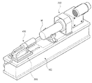
- Figure 2 is a perspective view of a deep hole processing apparatus for producing a pipe of atypical size according to an embodiment of the present invention.
- FIG. 3 is a front configuration diagram of a deep hole processing apparatus for manufacturing a pipe of atypical size according to an embodiment of the present invention.
- Figure 4 is a plan view of a deep hole processing apparatus for producing a pipe of a non-standard size according to an embodiment of the present invention.
- FIG. 5 is a cross-sectional view taken along the line A-A 'of FIG.
- FIG. 6 is a perspective view of the tubular holder and the bite of the cutting part of FIG.
- Figure 2 shows a perspective view of a deep hole processing apparatus for producing a pipe of a non-standard size according to an embodiment of the present invention.
- a deep hole processing apparatus for manufacturing a pipe having a non-standard size includes a frame 100, a material rotating part 200, a slide part 300, and a cutting part 400.
- the present invention is the main point to enter the material (M) in the longitudinal direction to the cutting portion 400 to be able to cut the inner side into a cylindrical shape, with the following description will be described each configuration in the following drawings.
- the non-standard size of the pipe means that the length and the pipe thickness are not standardized, and the present invention is an apparatus capable of manufacturing the non-standard pipe for the special purpose as described above.
- FIG. 3 is a front configuration of a deep hole processing apparatus for manufacturing a pipe of a non-standard size according to an embodiment of the present invention
- Figure 4 is a plan view of a deep hole processing apparatus for manufacturing a pipe of a non-standard size according to an embodiment of the present invention
- Figure 5 is It is A-A 'cross section figure of FIG.
- FIG. 3 is a front configuration diagram of a deep hole processing apparatus for manufacturing a pipe of atypical size according to an embodiment of the present invention.
- the frame 100 is formed of an iron structure and is positioned on the ground, and the material rotating part 200, the slide part 300, and the cutting part 400 for manufacturing a pie having an irregular size. You can install the configuration.
- the material rotating unit 200 is provided on the frame 100 to rotate the material is the same as the headstock of the shelf.
- the configuration is composed of a rotating means 220 that can rotate the material and the chuck 240 for fixing the material.
- the rotating means 220 is provided on one side of the upper frame.
- the rotating means 220 is the power of the motor 222 is transmitted to the reducer 224, the power is connected by the shaft connection with the chuck 240 in the reducer is rotated.
- the chuck 240 is provided at the end of the rotating means to clamp the long cylindrical material (M).
- the material (M) is a forged metal (forged bar) is to be processed into a pipe shape by cutting.
- the material M is rotated by the material rotating part 200, and the slide part 300 and the cutting part 400 installed at opposite sides of the material rotating part 200 will be described.
- the slide unit 300 is a device that can move the cutting unit 400 toward the material rotating unit 200 for the opposite side of the material rotating unit 200.
- the slide unit 300 may be composed of a rail 320 for the movement guide and a slide body 340 located on the rail.
- the rail 320 is formed to extend in the direction of the material rotating part 200 from the other side of the frame 100, the slide body 340 is provided on the rail can be moved along the rail. .
- the cutting unit 400 for cutting the material is coupled to the upper slide body 340.
- the cutting unit 400 is a device that contacts the rotating material (M) to cut the inner diameter of the material to be processed into a pipe shape.
- the cutting unit 400 is basically provided with a bite 440, it is composed of a tubular holder 420 for fixing the position of the bite 440.
- the tubular holder 420 is installed on the slide body 340.
- the bite 440 is installed at the end of the tubular holder 420, the bite 440 is in close contact with the material (M) in accordance with the movement of the slide body 340, the material ( M) can be rotated to cut the inner diameter into a cylindrical shape.
- tubular holder 420 may be divided into a main body 422 for fixing the bite 440 and a locking arm 424 for horizontally fixing the tubular holder.
- the main body 422 may be coupled to a pair such that the bite 440 is opposed to each other at one end thereof, and an inner space may be formed to accommodate the cut material.
- the cut material is cylindrical, there is an advantage that can be recycled.
- the locking arm 424 extends in communication with the other end of the main body 422 and is connected to an external cooling hose 425 at an end thereof to allow the cooling water to flow therein, and the introduced cooling water is the main body ( It is introduced into the inside of 422 to cool the cutting friction heat by the bite 440.
- the locking arm 424 is formed to be relatively smaller than the diameter of the main body 422 may be fixed to the slide body 340.
- a semicircular seating groove is formed in the upper portion of the slide body 340, and a lower portion of the locking arm is seated, and an upper portion of the locking arm 424 is provided. It is characterized in that it is further provided with a coupling cover 360 that can be coupled to the slide body and bolted, detachable by fixing the locking arm to the slide body horizontally.
- the tubular holder 420 may be fixed to the slide body 340 by the coupling cover 360, and the tubular holder 420 may be easily replaced so that the tubular holder 420 may correspond to the case where the material is irregular.
- the slide operation unit 500 is provided to operate the slide body 340 on the rail.
- the slide operation unit 500 is a cylinder 520 in which the external fluid flows in and out of the lower portion of the frame 100, the rod 540 coupled to the cylinder end is moved before and after, It consists of a bracket 560 connecting between the rod and the slide body.
- the cutting body 400 which is connected to the slide body 340 connected to it is eventually fixed to the slide body 340 is the material rotating part 200
- the cutting operation can be performed by moving to the side.
- the material rotation unit 200 and the slide operation unit 500 can be controlled by the operation of each control.
- the control unit, the temperature sensor is installed in the portion where the material (M) and the tubular holder 220 in contact with each other to measure the temperature and when the temperature is above a predetermined temperature, the speed of the motor 222 of the material rotating unit 200 By controlling to decelerate below a predetermined speed and adjusting the fluid inflow of the cylinder to the slide operation part 500, the speed at which the tubular holder enters the material side can be slowed.
- control unit may increase the delivery pressure of the tank for supplying to the cooling hose.
- the frame 100 includes a conveyor 620 which is orbitally moved from the inner side of the frame to the outer side to move the chip, and a chip discharging device including a motor 640 which drives the conveyor. 600 may be further provided to quickly collect and collect the cut chips.
- FIG. 6 is a perspective view illustrating the tubular holder and the bite of the cutting part of FIG. 2.
- the main body 422 is formed with a side hole 421 formed in the shape cut off at the adjacent end to which the bite is coupled to discharge the chip of the material to the outside, outside the main body Guide groove 426 is formed in the longitudinal direction is characterized in that to guide the chip of the material discharged to the side hole to the side.
- the present invention provides the basic technical idea of providing a deep hole processing apparatus for manufacturing a pipe having a non-standard size, and within the scope of the basic idea of the present invention, the general knowledge of the art Of course, many other variations are possible for the possessor.
- the present invention relates to a deep hole processing apparatus for manufacturing a pipe of atypical size, and to a pipe manufacturing deep hole processing apparatus for atypical size, which can make a pipe by cutting a cylindrical material of cylindrical size, and recycle the cut cylindrical material. Available.
Landscapes
- Engineering & Computer Science (AREA)
- Mechanical Engineering (AREA)
- Punching Or Piercing (AREA)
- Turning (AREA)
Abstract
본 발명은 비정형 사이즈의 파이프 제작용 딥홀 가공장치에 관한 것으로, 프레임; 상기 프레임 상부 일측에 구비되는 회전수단과, 상기 회전수단 단부에 구비되어 길이가 긴 원통 소재를 클램핑하는 척으로 구성되는 소재회전부; 상기 프레임 상부 타측에서 상기 소재회전부측 방향으로 구비되는 레일과, 상기 레일 상부에 구비되어 상기 레일을 따라 이동 가능한 슬라이드몸체로 구성되는 슬라이드부; 및 상기 슬라이드몸체 상부에 설치되는 관형홀더와, 상기 관형홀더의 단부에 설치되어 상기 슬라이드몸체의 이동에 따라 상기 소재에 밀착 시 원통형상으로 내경을 절삭하는 바이트로 구성되는 절삭부;가 포함되는 것을 특징으로 한다.
Description
본 발명은 비정형 사이즈의 파이프 제작용 딥홀 가공장치에 관한 것으로, 비정형 사이즈의 소재를 원통형으로 절삭하여 파이프를 제작하고, 절삭된 원통형 소재를 재활용할 수 있는 비정형 사이즈의 파이프 제작용 딥홀 가공장치에 관한 기술이다.
홀(Hole) 가공용(Core 생산없음) 및 소형 파이프 가공용의 딥홀(Deep hole) 전용장비는 국내외적으로 통상의 기술로 사용되고 있다.
종래의 딥홀 절삭 장치는 도 1에 도시하였다.
도 1을 참조하면, 스핀들 헤드(10)는 도시되지 않은 컬럼에 수직으로 이동가능하게 장착된다. 참조번호 12는 작업편(W)이 위치되는 테이블을 나타낸다. X축은 횡방향으로의 테이블(12)의 이동의 제어를 위한 축이고, Y축은 스핀들 헤드(10)의 수직 이동의 제어를 위한 축이다. Z축은 길이 방향으로의 테이블(12)의 이동의 제어를 위한 축이다.
그리고, 스핀들 헤드(10)에는 수평 위치에 스핀들(14)이 제공된다. 작업편(W)에 딥홀(15)을 기계가공할 때, 공구로서의 건 드릴(16)이 스핀들(14)에 장착된다. 이 실시예에서, 작업편(W)은 자동차의 범퍼 또는 인스트루먼트 패널의 성형을 위한 대형 몰드이고, 딥홀(15)로서의 냉각 홀이 작업편(W)을 통해서 길이 방향으로 드릴 가공된다. 700㎜ 이상의 길이를 갖는 건 드릴이 이 실시예에서와 같이 딥홀의 기계가공에 일반적으로 이용된다.
그러나, 종래의 상용화된 딥홀(Deep Hole) 장비들은 툴(Tool)의 두께가 50mm ~ 100mm로 특정된 내경기준만의 사이즈(Size) 및 가공길이 기준으로만 제작이 가능하다.
또한, 종래의 기술은 소재에 홀을 형성하거나, 또한 파이프 내측 홀을 가공하는 정도에 지나지 않았고, 직경이 큰 소재를 파이프 형상으로 만들기에는 적합하지 않은 문제점이 있어왔다.
본 발명은 상기와 같은 문제점을 해결하기 위하여 안출된 것으로, 가공되는 소재인 단조바를 가공하기 위해 툴자체의 파이프가공 두께 자체를 최소화하고 가공 후 내경재를 재활용할 수 있도록 하는 비정형 사이즈의 파이프 제작용 딥홀 가공장치를 제공하고자 하는데 그 목적이 있다.
상기와 같은 목적을 달성하기 위하여 본 발명은 프레임; 상기 프레임 상부 일측에 구비되는 회전수단과, 상기 회전수단 단부에 구비되어 길이가 긴 원통 소재를 클램핑하는 척으로 구성되는 소재회전부; 상기 프레임 상부 타측에서 상기 소재회전부측 방향으로 구비되는 레일과, 상기 레일 상부에 구비되어 상기 레일을 따라 이동 가능한 슬라이드몸체로 구성되는 슬라이드부; 및 상기 슬라이드몸체 상부에 설치되는 관형홀더와, 상기 관형홀더의 단부에 설치되어 상기 슬라이드몸체의 이동에 따라 상기 소재에 밀착 시 원통형상으로 내경을 절삭하는 바이트로 구성되는 절삭부;가 포함되는 것을 특징으로 한다.
상기 관형홀더는, 일측단에 상기 바이트가 결합되고, 절삭된 소재를 내부로 수용하는 관형 메인바디와, 상기 메인바디의 타측단에 연통되게 연장되어 외부의 냉각호스와 연결되는 로킹암으로 구성되는 것을 특징으로 한다.
상기 메인바디는, 상기 바이트가 결합된 인근 단부에서 절개된 형상으로 형성된 측면홀이 형성되어 소재의 칩을 외부로 배출하고, 상기 메인바디 외측에 길이방향으로 유도홈이 형성되어 상기 측면홀로 배출된 소재의 칩을 가이드하는 것을 특징으로 한다.
상기 슬라이드몸체 상부에는 반원 형상의 안착홈이 형성되어 상기 로킹암의 하부가 안착되고, 상기 로킹암의 상부에는 상기 로킹암 상부를 수용하여 상기 슬라이드몸체와 결합,분리 가능한 결합덮개가 더 구비되는 것을 특징으로 한다.
상기 프레임에는, 하부에 외부의 유체가 유,출입에 되는 실린더와, 상기 실린더 단부에 결합되어 전,후 이동되는 로드와, 상기 로드와 상기 슬라이드몸체 사이를 연결하는 브라켓으로 구성된 슬라이드작동부가 더 구비되는 것을 특징으로 한다.
*상기 프레임에는 상기 프레임의 내측에서 외측으로 궤도 운동되어 칩을 이동되게 하는 컨베이어와 상기 컨베이어를 구동되게 하는 모터로 구성되는 칩배출장치가 더 구비되는 것을 특징으로 한다.
상기와 같은 구성의 본 발명에 따르면, 다음과 같은 효과를 기대할 수 있을 것이다.
우선, 비정형 사이즈의 파이프 생산을 위한 전용장비 및 전용 툴을 개발하여 기존의 성형용 파이프 제작의 생산공정을 단축하여 생산성을 향상시킬 수 있다.
또한, 소재 내부를 원통형으로 절삭하여 파이프를 제작하므로, 원통형 소재를 재활용이 쉬운 이점이 있다.
도 1은 종래에 따른 딥홀 절삭 장치의 예시도.
도 2는 본 발명의 실시예에 따른 비정형 사이즈의 파이프 제작용 딥홀 가공장치의 사시도.
도 3은 본 발명의 실시예에 따른 비정형 사이즈의 파이프 제작용 딥홀 가공장치의 정면 구성도.
도 4는 본 발명의 실시예에 따른 비정형 사이즈의 파이프 제작용 딥홀 가공장치의 평면도.
도 5는 도 3의 A-A'단면도.
도 6은 도 2의 절삭부의 관형홀더와 바이트 상세 사시도.
이하, 첨부된 도면을 참고로 본 발명의 바람직한 실시예에 대하여 설명하기로 한다.
도 2는 본 발명의 실시예에 따른 비정형 사이즈의 파이프 제작용 딥홀 가공장치의 사시도를 나타낸 것이다.
도 2를 참조하면, 본 발명인 비정형 사이즈의 파이프 제작용 딥홀 가공장치는 크게 프레임(100), 소재회전부(200), 슬라이드부(300) 및 절삭부(400)가 포함되어 이루어진다.
본 발명은 절삭부(400)로 소재(M)를 길이방향으로 진입하여 내측을 원통형상으로 절삭 가공할 수 있게 하는 것을 주요 요지로 하는데 이를 유념하면서 다음의 도면으로 각 구성을 설명하기로 한다.
본원발명에서 비정형 사이즈의 파이프의 의미는 길이, 파이프두께가 규격화되지 않은 것을 의미하는 것이고, 본원발명은 위와 같은 특수 목적을 위한 비정형 파이프를 제작할 수 있는 장치이다.
도 3은 본 발명의 실시예에 따른 비정형 사이즈의 파이프 제작용 딥홀 가공장치의 정면 구성이고, 도 4는 본 발명의 실시예에 따른 비정형 사이즈의 파이프 제작용 딥홀 가공장치의 평면도이며, 도 5는 도 3의 A-A'단면도이다.
도 3은 본 발명의 실시예에 따른 비정형 사이즈의 파이프 제작용 딥홀 가공장치의 정면 구성도이다.
도 3을 참조하면, 상기 프레임(100)은 철제 구조물로 형성되어 지면상에 위치하게 되고, 비정형 사이즈의 파이를 제작하기 위한 상기 소재회전부(200), 슬라이드부(300) 및 절삭부(400)의 구성을 설치할 수 있다.
상기 소재회전부(200)는 상기 프레임(100) 상에 구비되어 소재를 회전할 수 있도록 하는 구성으로 선반의 주축대와 동일하다.
그 구성은 소재를 회전할 수 있는 회전수단(220)과 소재를 고정하는 척(240)으로 구성된다.
상세하게, 상기 회전수단(220)은 상기 프레임 상부 일측에 구비되게 된다.
상기 회전수단(220)은 모터(222)의 동력이 감속기(224)에 전달되며 감속기에서 상기 척(240)과 축 연결에 의해 동력이 연결되어 회전하게 된다.
그리고, 상기 척(240)은 상기 회전수단 단부에 구비되어 길이가 긴 원통 소재(M)를 클램핑 할 수 있는 것이다.
여기서, 소재(M)는 단조금속(forged bar)이며 절삭 가공에 의해 파이프 형상으로 가공되게 된다.
상기 소재회전부(200)에 의해 소재(M)가 회전되게 되고, 이를 절삭하기 위해 맞은편에 설치된 슬라이드부(300)와 절삭부(400)에 대해서 설명하기로 한다.
상기 슬라이드부(300)는 상기 소재회전부(200)의 맞은편에 위하여 상기 절삭부(400)를 소재회전부(200)측으로 이동할 수 있는 장치이다.
여기서, 상기 슬라이드부(300)는 이동 가이드를 위한 레일(320)과 레일 상에 위치한 슬라이드몸체(340)로 구성할 수 있다.
상기 레일(320)은 상기 프레임(100) 상부 타측에서 상기 소재회전부(200)측 방향으로 길게 형성되게 되고, 상기 슬라이드몸체(340)는 상기 레일 상부에 구비되어 상기 레일을 따라 이동 가능할 수 있는 것이다.
여기서, 상기 슬라이드몸체(340) 상부에는 소재를 절삭하기 위한 절삭부(400)가 결합된다.
상기 절삭부(400)는 회전하는 소재(M)와 접촉되어 상기 소재의 내경을 절삭하여 파이프 형상으로 가공하는 장치이다.
상기 절삭부(400)는 기본적으로 바이트(440)가 구비되게 되고, 이러한 바이트(440)의 위치를 고정하기 위한 관형홀더(420)로 구성되게 된다.
먼저, 상기 관형홀더(420)는 상기 슬라이드몸체(340) 상부에 설치되게 된다.
그리고, 상기 바이트(440)는 상기 관형홀더(420)의 단부에 설치되어 상기 슬라이드몸체(340)의 이동에 따라 상기 바이트(440)가 상기 소재(M)에 밀착되게 되고, 이때, 상기 소재(M)가 회전되어 원통형상으로 내경을 절삭할 수 있다.
여기서, 상기 관형홀더(420)는 그 구성이 바이트(440)를 고정하는 메인바디(422)와, 관형홀더를 수평되게 고정을 위한 로킹암(424)으로 구분할 수 있다.
상세하게, 상기 메인바디(422)는 일측단에 상기 바이트(440)가 상호 대향되게 한 쌍이 결합되고, 내부 공간이 형성되어 절삭된 소재를 내부로 수용할 수 있다.
여기서, 절삭된 소재는 원통형상이 되므로 재활용할 수 있는 이점이 있다.
그리고, 상기 로킹암(424)은 상기 메인바디(422)의 타측단에 연통되게 연장되어 단부에는 외부의 냉각호스(425)와 연결되어 냉각수가 유입할 수 있고, 유입된 냉각수는 상기 메인바디(422)의 내부로 유입되어 상기 바이트(440)에 의한 절삭 마찰열을 냉각할 수 있게 된다.
여기서, 상기 로킹암(424)은 상기 메인바디(422)의 직경보다 상대적으로 작도록 형성되게 되고 상기 슬라이드몸체(340)에 고정할 수 있다.
상기 로킹암을 상기 슬라이드몸체에 고정하기 위하여, 상기 슬라이드몸체(340) 상부에는 반원 형상의 안착홈이 형성되어 상기 로킹암의 하부가 안착되고, 상기 로킹암(424)의 상부에는 상기 로킹암 상부를 수용하여 상기 슬라이드몸체와 볼팅으로 결합,분리 가능한 결합덮개(360)가 더 구비되어 상기 로킹암을 상기 슬라이드몸체에 수평되게 고정하는 것을 특징으로 한다.
결국, 상기 결합덮개(360)에 의해 관형홀더(420)가 슬라이드몸체(340)에 고정할 수 있고, 상기 관형홀더(420)를 쉽게 교체할 수 있으므로 소재가 비정형인 경우 이에 맞게 대응할 수 있다.
그리고, 상기 슬라이드몸체(340)를 레일 상에서 작동되게 하기 위하여 슬라이드작동부(500)가 구비되게 된다.
여기서, 상기 슬라이드작동부(500)는 상기 프레임(100)의 하부에 외부의 유체가 유,출입에 되는 실린더(520)와, 상기 실린더 단부에 결합되어 전,후 이동되는 로드(540)와, 상기 로드와 상기 슬라이드몸체 사이를 연결하는 브라켓(560)으로 구성된다.
이때, 상기 로드(540)가 전,후로 작동되면 이와 연결된 상기 슬라이드몸체(340)가 전,후로 이동되어 결국 상기 슬라이드몸체(340)에 고정된 상기 절삭부(400)가 상기 소재회전부(200) 측으로 이동하여 절삭 작업을 진행할 수 있다.
한편, 상기 소재회전부(200)와 슬라이드작동부(500)를 제어부에 의해 각각의 작동을 제어할 수 있다.
제어부는, 소재(M)와 관형홀더(220)가 상호 접촉되는 부분에 온도감지센서가 설치되어 온도를 측정하고 기설정된 온도 이상이 되면, 상기 소재회전부(200)의 모터(222)의 속도를 기설정된 속도 이하로 감속하도록 제어하고, 상기 슬라이드작동부(500)에 실린더의 유체 유입량을 조절하여 관형홀더가 소재측으로 진입되는 속도를 늦출 수 있다.
물론, 상기 제어부는 냉각호스로 공급하기 위한 탱크의 송출압력을 높일 수 도 있다.
한편, 도 5를 참조하면 상기 프레임(100)에는 상기 프레임의 내측에서 외측으로 궤도 운동되어 칩을 이동되게 하는 컨베이어(620)와 상기 컨베이어를 구동되게 하는 모터(640)로 구성되는 칩배출장치(600)가 더 구비되어 절삭된 칩을 빠르게 배출하여 수거할 수 있다.
도 6은 도 2의 절삭부의 관형홀더와 바이트 상세 사시도이다.
한편, 도 6을 참조하면, 상기 메인바디(422)는 상기 바이트가 결합된 인근 단부에서 절개된 형상으로 형성된 측면홀(421)이 형성되어 소재의 칩을 외부로 배출하고, 상기 메인바디 외측에 길이방향으로 유도홈(426)이 형성되어 상기 측면홀로 배출된 소재의 칩을 측면으로 가이드하는 것을 특징으로 한다.
이상과 같이 본 발명은 비정형 사이즈의 파이프 제작용 딥홀 가공장치를 제공하는 것을 기본적인 기술적인 사상으로 하고 있음을 알 수 있으며, 이와 같은 본 발명의 기본적인 사상의 범주내에서, 당업계의 통상의 지식을 가진 자에게 있어서는 다른 많은 변형이 가능함은 물론이다.
본 발명은 비정형 사이즈의 파이프 제작용 딥홀 가공장치에 관한 것으로, 비정형 사이즈의 소재를 원통형으로 절삭하여 파이프를 제작하고, 절삭된 원통형 소재를 재활용할 수 있는 비정형 사이즈의 파이프 제작용 딥홀 가공장치 분야에 이용가능하다.
Claims (6)
- 프레임(100);상기 프레임 상부 일측에 구비되는 회전수단(220)과, 상기 회전수단 단부에 구비되어 길이가 긴 원통 소재를 클램핑하는 척(240)으로 구성되는 소재회전부(200);상기 프레임 상부 타측에서 상기 소재회전부측 방향으로 구비되는 레일(320)과, 상기 레일 상부에 구비되어 상기 레일을 따라 이동 가능한 슬라이드몸체(340)로 구성되는 슬라이드부(300); 및상기 슬라이드몸체 상부에 설치되는 관형홀더(420)와, 상기 관형홀더의 단부에 설치되어 상기 슬라이드몸체의 이동에 따라 상기 소재에 밀착 시 원통형상으로 내경을 절삭하는 바이트(440)로 구성되는 절삭부(400);가 포함되는 것을 특징으로 하는 비정형 사이즈의 파이프 제작용 딥홀 가공장치.
- 제1항에 있어서,상기 관형홀더(420)는,일측단에 상기 바이트가 결합되고, 절삭된 소재를 내부로 수용하는 관형 메인바디(422)와, 상기 메인바디의 타측단에 연통되게 연장되어 외부의 냉각호스와 연결되는 로킹암(424)으로 구성되는 것을 특징으로 하는 비정형 사이즈의 파이프 제작용 딥홀 가공장치.
- 제2항에 있어서,상기 메인바디(422)는,상기 바이트가 결합된 인근 단부에서 절개된 형상으로 형성된 측면홀(421)이 형성되어 소재의 칩을 외부로 배출하고, 상기 메인바디 외측에 길이방향으로 유도홈(426)이 형성되어 상기 측면홀로 배출된 소재의 칩을 가이드하는 것을 특징으로 하는 비정형 사이즈의 파이프 제작용 딥홀 가공장치.
- 제2항에 있어서,상기 슬라이드몸체(340) 상부에는 반원 형상의 안착홈이 형성되어 상기 로킹암의 하부가 안착되고,상기 로킹암(425)의 상부에는 상기 로킹암 상부를 수용하여 상기 슬라이드몸체와 결합,분리 가능한 결합덮개(360)가 더 구비되는 것을 특징으로 하는 비정형 사이즈의 파이프 제작용 딥홀 가공장치.
- 제1항에 있어서,상기 프레임(100)에는,하부에 외부의 유체가 유,출입에 되는 실린더(520)와, 상기 실린더 단부에 결합되어 전,후 이동되는 로드(540)와, 상기 로드와 상기 슬라이드몸체 사이를 연결하는 브라켓(560)으로 구성된 슬라이드작동부(500)가 더 구비되는 것을 특징으로 하는 비정형 사이즈의 파이프 제작용 딥홀 가공장치.
- 제1항에 있어서,상기 프레임(100)에는,상기 프레임의 내측에서 외측으로 궤도 운동되어 칩을 이동되게 하는 컨베이어(620)와 상기 컨베이어를 구동되게 하는 모터(640)로 구성되는 칩배출장치(600)가 더 구비되는 것을 특징으로 하는 비정형 사이즈의 파이프 제작용 딥홀 가공장치.
Applications Claiming Priority (2)
| Application Number | Priority Date | Filing Date | Title |
|---|---|---|---|
| KR1020140029184A KR101444240B1 (ko) | 2014-03-12 | 2014-03-12 | 비정형 사이즈의 파이프 제작용 딥홀 가공장치 |
| KR10-2014-0029184 | 2014-03-12 |
Publications (1)
| Publication Number | Publication Date |
|---|---|
| WO2015137672A1 true WO2015137672A1 (ko) | 2015-09-17 |
Family
ID=52288962
Family Applications (1)
| Application Number | Title | Priority Date | Filing Date |
|---|---|---|---|
| PCT/KR2015/002248 Ceased WO2015137672A1 (ko) | 2014-03-12 | 2015-03-09 | 비정형 사이즈의 파이프 제작용 딥홀 가공장치 |
Country Status (2)
| Country | Link |
|---|---|
| KR (1) | KR101444240B1 (ko) |
| WO (1) | WO2015137672A1 (ko) |
Citations (5)
| Publication number | Priority date | Publication date | Assignee | Title |
|---|---|---|---|---|
| JPH08168908A (ja) * | 1994-12-16 | 1996-07-02 | Hosoi Kosakusho:Kk | 深穴加工のための切削液供給装置および方法 |
| JP2000042816A (ja) * | 1998-07-27 | 2000-02-15 | Ondo Kosakusho:Kk | 穴明け加工装置 |
| JP2005125450A (ja) * | 2003-10-23 | 2005-05-19 | Sugino Mach Ltd | ガンドリルマシン |
| KR100988968B1 (ko) * | 2007-03-01 | 2010-10-20 | 도시바 기카이 가부시키가이샤 | 딥홀을 기계가공하기 위한 방법 및 장치 |
| JP2010284771A (ja) * | 2009-06-15 | 2010-12-24 | Howa Mach Ltd | 深孔加工機の長尺ドリル支持構造 |
-
2014
- 2014-03-12 KR KR1020140029184A patent/KR101444240B1/ko active Active
-
2015
- 2015-03-09 WO PCT/KR2015/002248 patent/WO2015137672A1/ko not_active Ceased
Patent Citations (5)
| Publication number | Priority date | Publication date | Assignee | Title |
|---|---|---|---|---|
| JPH08168908A (ja) * | 1994-12-16 | 1996-07-02 | Hosoi Kosakusho:Kk | 深穴加工のための切削液供給装置および方法 |
| JP2000042816A (ja) * | 1998-07-27 | 2000-02-15 | Ondo Kosakusho:Kk | 穴明け加工装置 |
| JP2005125450A (ja) * | 2003-10-23 | 2005-05-19 | Sugino Mach Ltd | ガンドリルマシン |
| KR100988968B1 (ko) * | 2007-03-01 | 2010-10-20 | 도시바 기카이 가부시키가이샤 | 딥홀을 기계가공하기 위한 방법 및 장치 |
| JP2010284771A (ja) * | 2009-06-15 | 2010-12-24 | Howa Mach Ltd | 深孔加工機の長尺ドリル支持構造 |
Also Published As
| Publication number | Publication date |
|---|---|
| KR101444240B1 (ko) | 2014-11-04 |
Similar Documents
| Publication | Publication Date | Title |
|---|---|---|
| CN105773167A (zh) | 管端自动加工系统 | |
| KR101518375B1 (ko) | 유니버셜죠인트용 요크 가공 장치 및 방법 | |
| US3893355A (en) | Coolant supply system for cutting tools in a machine tool | |
| CN107953146B (zh) | 曲轴加工多工序组合机床 | |
| CN107552837A (zh) | 一种通讯塔搭建用管材钻孔装置 | |
| CN105458705A (zh) | 一种万向节十字轴钻铣组合机床 | |
| CN108580956A (zh) | 一种双工位自动化模具打孔设备 | |
| CN204686094U (zh) | 置有冷却循环的轨道打孔钻床 | |
| CN110508699B (zh) | 一种基于管类扩孔设备的扩孔方法 | |
| CN206578538U (zh) | 一种方向盘压铸件自动三轴钻孔攻丝机 | |
| CN110496984B (zh) | 电机外壳开孔辅助设备 | |
| CN210359447U (zh) | 一种仿形钻铣机床 | |
| CN105436544B (zh) | 一种立式数控三坐标带df系统的钻床 | |
| WO2015137672A1 (ko) | 비정형 사이즈의 파이프 제작용 딥홀 가공장치 | |
| CN108237256A (zh) | 一种钢管切割装置 | |
| KR100656629B1 (ko) | 수치제어 선반의 자동 척 교환장치 | |
| CN103008716B (zh) | 一种用于钢管钻孔的半自动对头钻床 | |
| CN110181083B (zh) | 一种污水净化系统用多通阀的加工设备 | |
| CN214925049U (zh) | 一种吹塑管钻孔设备 | |
| CN107138978A (zh) | 一种方向盘压铸件自动三轴钻孔机的工件夹持平台 | |
| CN202447932U (zh) | 管件钻孔定位夹具 | |
| CN206578537U (zh) | 一种方向盘压铸件自动三轴钻孔机的钻孔攻丝装置 | |
| CN117047158A (zh) | 一种多工位外齿圈钻孔设备 | |
| CN212652713U (zh) | 一种新型钻孔设备 | |
| CN222856757U (zh) | 一种用于卧式车床的深孔加工装置 |
Legal Events
| Date | Code | Title | Description |
|---|---|---|---|
| 121 | Ep: the epo has been informed by wipo that ep was designated in this application |
Ref document number: 15762357 Country of ref document: EP Kind code of ref document: A1 |
|
| NENP | Non-entry into the national phase |
Ref country code: DE |
|
| 32PN | Ep: public notification in the ep bulletin as address of the adressee cannot be established |
Free format text: NOTING OF LOSS OF RIGHTS PURSUANT TO RULE 112(1) EPC (EPO FORM 1205N DATED 23/12/2016) |
|
| 122 | Ep: pct application non-entry in european phase |
Ref document number: 15762357 Country of ref document: EP Kind code of ref document: A1 |