WO2015140876A1 - Dispositif à cycle de réfrigération - Google Patents
Dispositif à cycle de réfrigération Download PDFInfo
- Publication number
- WO2015140876A1 WO2015140876A1 PCT/JP2014/057034 JP2014057034W WO2015140876A1 WO 2015140876 A1 WO2015140876 A1 WO 2015140876A1 JP 2014057034 W JP2014057034 W JP 2014057034W WO 2015140876 A1 WO2015140876 A1 WO 2015140876A1
- Authority
- WO
- WIPO (PCT)
- Prior art keywords
- refrigerant
- refrigeration cycle
- pipe
- cycle apparatus
- refrigerant circuit
- Prior art date
- Legal status (The legal status is an assumption and is not a legal conclusion. Google has not performed a legal analysis and makes no representation as to the accuracy of the status listed.)
- Ceased
Links
Images







Classifications
-
- F—MECHANICAL ENGINEERING; LIGHTING; HEATING; WEAPONS; BLASTING
- F25—REFRIGERATION OR COOLING; COMBINED HEATING AND REFRIGERATION SYSTEMS; HEAT PUMP SYSTEMS; MANUFACTURE OR STORAGE OF ICE; LIQUEFACTION SOLIDIFICATION OF GASES
- F25B—REFRIGERATION MACHINES, PLANTS OR SYSTEMS; COMBINED HEATING AND REFRIGERATION SYSTEMS; HEAT PUMP SYSTEMS
- F25B49/00—Arrangement or mounting of control or safety devices
- F25B49/02—Arrangement or mounting of control or safety devices for compression type machines, plants or systems
-
- F—MECHANICAL ENGINEERING; LIGHTING; HEATING; WEAPONS; BLASTING
- F25—REFRIGERATION OR COOLING; COMBINED HEATING AND REFRIGERATION SYSTEMS; HEAT PUMP SYSTEMS; MANUFACTURE OR STORAGE OF ICE; LIQUEFACTION SOLIDIFICATION OF GASES
- F25B—REFRIGERATION MACHINES, PLANTS OR SYSTEMS; COMBINED HEATING AND REFRIGERATION SYSTEMS; HEAT PUMP SYSTEMS
- F25B49/00—Arrangement or mounting of control or safety devices
- F25B49/005—Arrangement or mounting of control or safety devices of safety devices
-
- F—MECHANICAL ENGINEERING; LIGHTING; HEATING; WEAPONS; BLASTING
- F25—REFRIGERATION OR COOLING; COMBINED HEATING AND REFRIGERATION SYSTEMS; HEAT PUMP SYSTEMS; MANUFACTURE OR STORAGE OF ICE; LIQUEFACTION SOLIDIFICATION OF GASES
- F25B—REFRIGERATION MACHINES, PLANTS OR SYSTEMS; COMBINED HEATING AND REFRIGERATION SYSTEMS; HEAT PUMP SYSTEMS
- F25B13/00—Compression machines, plants or systems, with reversible cycle
-
- F—MECHANICAL ENGINEERING; LIGHTING; HEATING; WEAPONS; BLASTING
- F25—REFRIGERATION OR COOLING; COMBINED HEATING AND REFRIGERATION SYSTEMS; HEAT PUMP SYSTEMS; MANUFACTURE OR STORAGE OF ICE; LIQUEFACTION SOLIDIFICATION OF GASES
- F25B—REFRIGERATION MACHINES, PLANTS OR SYSTEMS; COMBINED HEATING AND REFRIGERATION SYSTEMS; HEAT PUMP SYSTEMS
- F25B2600/00—Control issues
- F25B2600/02—Compressor control
- F25B2600/021—Inverters therefor
-
- F—MECHANICAL ENGINEERING; LIGHTING; HEATING; WEAPONS; BLASTING
- F25—REFRIGERATION OR COOLING; COMBINED HEATING AND REFRIGERATION SYSTEMS; HEAT PUMP SYSTEMS; MANUFACTURE OR STORAGE OF ICE; LIQUEFACTION SOLIDIFICATION OF GASES
- F25B—REFRIGERATION MACHINES, PLANTS OR SYSTEMS; COMBINED HEATING AND REFRIGERATION SYSTEMS; HEAT PUMP SYSTEMS
- F25B2600/00—Control issues
- F25B2600/25—Control of valves
- F25B2600/2519—On-off valves
-
- F—MECHANICAL ENGINEERING; LIGHTING; HEATING; WEAPONS; BLASTING
- F25—REFRIGERATION OR COOLING; COMBINED HEATING AND REFRIGERATION SYSTEMS; HEAT PUMP SYSTEMS; MANUFACTURE OR STORAGE OF ICE; LIQUEFACTION SOLIDIFICATION OF GASES
- F25B—REFRIGERATION MACHINES, PLANTS OR SYSTEMS; COMBINED HEATING AND REFRIGERATION SYSTEMS; HEAT PUMP SYSTEMS
- F25B2600/00—Control issues
- F25B2600/25—Control of valves
- F25B2600/2525—Pressure relief valves
-
- F—MECHANICAL ENGINEERING; LIGHTING; HEATING; WEAPONS; BLASTING
- F25—REFRIGERATION OR COOLING; COMBINED HEATING AND REFRIGERATION SYSTEMS; HEAT PUMP SYSTEMS; MANUFACTURE OR STORAGE OF ICE; LIQUEFACTION SOLIDIFICATION OF GASES
- F25B—REFRIGERATION MACHINES, PLANTS OR SYSTEMS; COMBINED HEATING AND REFRIGERATION SYSTEMS; HEAT PUMP SYSTEMS
- F25B2700/00—Sensing or detecting of parameters; Sensors therefor
- F25B2700/19—Pressures
- F25B2700/193—Pressures of the compressor
- F25B2700/1931—Discharge pressures
-
- F—MECHANICAL ENGINEERING; LIGHTING; HEATING; WEAPONS; BLASTING
- F25—REFRIGERATION OR COOLING; COMBINED HEATING AND REFRIGERATION SYSTEMS; HEAT PUMP SYSTEMS; MANUFACTURE OR STORAGE OF ICE; LIQUEFACTION SOLIDIFICATION OF GASES
- F25B—REFRIGERATION MACHINES, PLANTS OR SYSTEMS; COMBINED HEATING AND REFRIGERATION SYSTEMS; HEAT PUMP SYSTEMS
- F25B2700/00—Sensing or detecting of parameters; Sensors therefor
- F25B2700/21—Temperatures
- F25B2700/2115—Temperatures of a compressor or the drive means therefor
- F25B2700/21152—Temperatures of a compressor or the drive means therefor at the discharge side of the compressor
-
- Y—GENERAL TAGGING OF NEW TECHNOLOGICAL DEVELOPMENTS; GENERAL TAGGING OF CROSS-SECTIONAL TECHNOLOGIES SPANNING OVER SEVERAL SECTIONS OF THE IPC; TECHNICAL SUBJECTS COVERED BY FORMER USPC CROSS-REFERENCE ART COLLECTIONS [XRACs] AND DIGESTS
- Y02—TECHNOLOGIES OR APPLICATIONS FOR MITIGATION OR ADAPTATION AGAINST CLIMATE CHANGE
- Y02B—CLIMATE CHANGE MITIGATION TECHNOLOGIES RELATED TO BUILDINGS, e.g. HOUSING, HOUSE APPLIANCES OR RELATED END-USER APPLICATIONS
- Y02B30/00—Energy efficient heating, ventilation or air conditioning [HVAC]
- Y02B30/70—Efficient control or regulation technologies, e.g. for control of refrigerant flow, motor or heating
Definitions
- the present invention relates to a refrigeration cycle apparatus using a refrigerant having a property of causing a disproportionation reaction as a main component.
- HFC refrigerant having no carbon double bond in the composition for example, R32 (CH 2 F 2 ; difluoromethane) having a lower GWP than R410A.
- a halogenated hydrocarbon having a carbon double bond in the composition which is a kind of HFC refrigerant like R32.
- HFO-1234yf CF 3 CF ⁇ CH 2 ; tetrafluoropropene
- HFO-1234ze CF 3 —CH ⁇ CHF
- an HFC refrigerant having a carbon double bond is changed to an olefin (unsaturated hydrocarbon having a carbon double bond). It is often expressed as “HFO refrigerant” using “O” (called olefin).
- HFO-1123 (CF 2 ⁇ CHF; 1, 1, 2 trifluoroethene (ethylene)), which is a kind of HFO refrigerant, is known as well as HFO-1234yf and HFO-1234ze.
- This HFO-1123 has a property of causing a disproportionation reaction (autolysis reaction).
- a disproportionation reaction occurs, the reaction proceeds explosively.
- the disproportionation reaction generates heat and HF (hydrogen fluoride) as shown in the following reaction formula.
- CF 2 CHF ⁇ 1 / 2CF 4 + 3 / 2C + HF + 44.7 kcal / mol Therefore, when HFO-1123 is used, care must be taken not to cause a disproportionation reaction.
- Patent Document 1 An air conditioner has been proposed that uses a combustible refrigerant and immediately responds to the leakage of the refrigerant when the refrigerant leaks (see, for example, Patent Document 1).
- the air conditioner described in Patent Document 1 is “the indoor unit and the outdoor unit are integrated, and the indoor heat exchanger, the outdoor heat exchanger, the compressor, and the expansion device are connected in a ring shape through a pipe,
- a gas sensor is provided on the indoor side
- a refrigerant discharge unit is provided on the outdoor side
- the gas sensor detects refrigerant leakage from the refrigeration cycle to the outside. The part is opened and the refrigerant is exhausted to the outside ”.
- the present invention has been made to solve the above-described problems, and even when a refrigerant having a property of causing a disproportionation reaction is used as a main component, a refrigeration cycle that can ensure sufficient safety.
- An object is to provide an apparatus.
- a refrigeration cycle apparatus has a refrigerant circuit to which at least a compressor, a first heat exchanger, a decompression mechanism, and a second heat exchanger are connected, and has a property of causing a disproportionation reaction in the refrigerant circuit.
- the refrigerant when at least one of the pressure and temperature of the refrigerant in the refrigerant circuit approaches at least one of the pressure and temperature at which the refrigerant causes a disproportionation reaction, that is, the refrigerant is incomplete. Since the refrigerant is discharged from the refrigerant circuit before the leveling reaction occurs, even if the refrigerant causing the leveling reaction is used as a main component, sufficient safety can be ensured.
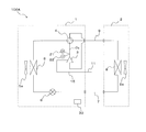
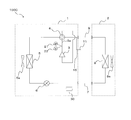
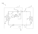
- FIG. 1 is a schematic configuration diagram showing an example of a refrigerant circuit configuration of a refrigeration cycle apparatus (hereinafter referred to as refrigeration cycle apparatus 100A) according to Embodiment 1 of the present invention.
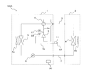
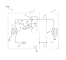
- FIG. 2 is a schematic configuration diagram showing another example of the refrigerant circuit configuration of the refrigeration cycle apparatus 100A.
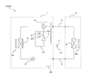
- FIG. 3 is a schematic configuration diagram showing still another example of the refrigerant circuit configuration of the refrigeration cycle apparatus 100A.
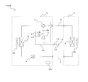
- FIG. 4 is a schematic configuration diagram showing still another example of the refrigerant circuit configuration of the refrigeration cycle apparatus 100A.
- the refrigeration cycle apparatus 100A will be described with reference to FIGS.
- the refrigeration cycle apparatus 100A is assumed to use a refrigerant having a property of causing a disproportionation reaction as a main component, and includes an outdoor unit 1 and an indoor unit 2.
- the outdoor unit 1 and the indoor unit 2 are connected via a liquid pipe 7 and a gas pipe 9.
- the outdoor unit (heat source unit) 1 includes a compressor 3 for compressing refrigerant, a four-way valve 4 as refrigerant circuit switching means for switching the refrigerant flow path, air around the outdoor unit 1 conveyed by the refrigerant and the outdoor blower 5a, and An outdoor heat exchanger (first heat exchanger) 5 for exchanging heat and an electronic expansion valve 6 (an example of a decompression mechanism) for controlling the flow rate of the refrigerant.
- the outdoor heat exchanger 5 has the outdoor air blower 5a which supplies air.
- the indoor unit (use-side unit) 2 exchanges heat between the refrigerant and the air around the indoor unit 2 conveyed by the indoor blower 8a, and cools or heats the indoor space by, for example, cooling or heating the indoor space.
- a heat exchanger (second heat exchanger) 8 is provided.
- the indoor heat exchanger 8 has an indoor blower 8a that supplies air.
- the compressor 3 for compressing the refrigerant it is preferable to use a positive displacement compressor of a type in which the rotation speed is controlled by an inverter circuit and the capacity is controlled.
- the positive displacement compressor include a rotary compressor, a scroll compressor, a screw compressor, and a reciprocating compressor.
- the compressor 3 is provided with an electric motor.
- a discharge pipe 3 a is connected to the compressor 3.
- the discharge pipe 3a is provided with a pressure detector 21 for measuring the discharge pressure of the refrigerant and a temperature detector 22 for measuring the discharge temperature of the refrigerant.
- the four-way valve 4 switches the refrigerant flow path according to a cooling / heating supply mode (for example, cooling operation mode) and a heating / heating supply mode (for example, heating operation mode).
- a cooling / heating supply mode for example, cooling operation mode
- a heating / heating supply mode for example, heating operation mode
- the refrigerant circuit switching unit may be configured by combining two refrigerant valves, for example, two two-way valves or three-way valves. Good.
- the case where the four-way valve 4 is provided is shown as an example, when the refrigerant circuit configuration in which the refrigerant flow path is not switched is adopted as the refrigeration cycle apparatus 100A, it is not necessary to provide the refrigerant circuit switching means.
- the outdoor heat exchanger 5 functions as a condenser or an evaporator, and can be constituted by, for example, a cross-fin type fin-and-tube heat exchanger constituted by heat transfer tubes and a large number of fins.
- a heat medium for example, water or brine
- the outdoor heat exchanger 5 is, for example, a microchannel heat exchanger, a shell-and-tube heat exchanger, a heat pipe heat exchanger, a double pipe heat exchanger, a plate A heat exchanger or the like may be used.
- a 1st heat exchanger is the outdoor heat exchanger 5
- a 1st heat exchanger is not limited to the outdoor heat exchanger 5
- a 1st heat exchanger is a heat source side. What is necessary is just a heat exchanger (namely, heat source side heat exchanger).
- the outdoor blower 5a supplies air to the outdoor heat exchanger 5, and is configured to be capable of changing the flow rate of air.
- a centrifugal fan or a multiblade fan driven by a motor such as a DC fan motor can be used as the outdoor fan 5a.
- a transfer device such as a pump may be provided instead of the outdoor fan 5a.
- the electronic expansion valve 6 can adjust the refrigerant flow rate.
- the pressure reducing mechanism the electronic expansion valve 6 having a structure with a variable throttle opening is described as an example.
- the present invention is not limited to this, and a mechanical expansion using a diaphragm for the pressure receiving portion. You may comprise a pressure reduction mechanism with a valve or a capillary tube.
- the indoor heat exchanger 8 functions as an evaporator or a condenser, and can be constituted by, for example, a cross-fin type fin-and-tube heat exchanger constituted by heat transfer tubes and a large number of fins. Note that, in the indoor heat exchanger 8, a case where heat is exchanged between the refrigerant and air is shown as an example, but heat exchange may be performed between the refrigerant and a heat medium (for example, water or brine) other than air.
- a heat medium for example, water or brine
- the indoor heat exchanger 8 is, for example, a microchannel heat exchanger, a shell-and-tube heat exchanger, a heat pipe heat exchanger, a double pipe heat exchanger, a plate A heat exchanger or the like may be used.
- a 2nd heat exchanger is the indoor heat exchanger 8
- a 2nd heat exchanger is not limited to the indoor heat exchanger 8
- a 2nd heat exchanger is a utilization side. What is necessary is just a heat exchanger (namely, utilization side heat exchanger).
- the indoor fan 8a supplies air to the indoor heat exchanger 8, and is configured to be capable of changing the flow rate of air.
- a centrifugal fan or a multiblade fan driven by a motor such as a DC fan motor can be used as the indoor fan 8a.
- a transfer device such as a pump may be provided instead of the indoor blower 8a.
- the outdoor unit 1 and the indoor unit 2 comprise a refrigerant circuit by connecting each element apparatus by the liquid pipe 7 and the gas pipe 9 which are refrigerant flow paths.
- the connection algebra of the outdoor unit 1 and the indoor unit 2 is not limited to one, and any one or each may be a plurality.
- the refrigeration cycle apparatus 100A includes a control device 30 that performs overall control of the refrigeration cycle apparatus 100A.
- the control device 30 controls each actuator (driving components such as the compressor 3, the four-way valve 4, the outdoor blower 5a, the electronic expansion valve 6, and the indoor blower 8a) based on the detection value from each detector.
- the control device 30 can be configured by hardware such as a circuit device that realizes the function, or can be configured by an arithmetic device such as a microcomputer or a CPU and software executed thereon.
- the four-way valve 4 in the cold supply mode (for example, cooling operation) in which cold heat is supplied from the indoor heat exchanger 8, the four-way valve 4 becomes a solid flow path, and a hot heat supply mode (for example, supplying warm heat from the indoor heat exchanger 8) In the heating operation), the four-way valve 4 is switched to the dotted flow path. Therefore, in the cold heat supply mode, the compressor 3, the four-way valve 4, the outdoor heat exchanger 5, the electronic expansion valve 6, the indoor heat exchanger 8, and the compressor 3 are connected in an annular shape in this order. In the heat supply mode, the compressor 3, the four-way valve 4, the indoor heat exchanger 8, the electronic expansion valve 6, the outdoor heat exchanger 5, and the compressor 3 are annularly connected in this order.
- the outdoor heat exchanger 5 functions as a condenser
- the indoor heat exchanger 8 functions as an evaporator.
- the outdoor heat exchanger 5 functions as an evaporator
- the indoor heat exchanger 8 functions as a condenser.
- HFO-1123 1, 1, 2 trifluoroethylene (HFO-1123) having a low GWP and a high operating pressure is used as a main component.
- HFO-1123 undergoes a disproportionation reaction in which a substance having heat and toxicity (HF) is generated under high temperature and high pressure.
- HFO-1123 CHF ⁇ 1 / 2CF 4 + 3 / 2C + HF + 44.7 kcal / mol
- the main component of HFO-1123 is that the content of other refrigerants (which may be a plurality of types of refrigerants) to be mixed, including the fact that HFO-1123 is used alone, It means that the content is not exceeded by mass%.
- the refrigeration cycle apparatus 100A when at least one of the pressure and temperature of the refrigerant in the refrigerant circuit approaches at least one of the pressure and temperature at which HFO-1123 causes a disproportionation reaction, that is, HFO-1123 Before the disproportionation reaction takes place, the refrigerant mainly composed of HFO-1123 is released from the refrigerant circuit to prevent the occurrence of the disproportionation reaction. Specifically, the refrigeration cycle apparatus 100A releases the refrigerant from the refrigerant circuit before the HFO-1123 undergoes a disproportionation reaction via the refrigerant release pipe 15 connected to the shell of the compressor 3. I am doing so.
- the compressor 3 includes an electric motor in the shell, there is a possibility that the compressor 3 may become an ignition source of the refrigerant having a high temperature and a high pressure. Therefore, a pipe 15 is connected to the compressor 3 so that the refrigerant is directly discharged from the compressor 3.
- the refrigerant whose main component is HFO-1123 becomes 0.9 times the limit pressure causing the disproportionation reaction of HFO-1123, or the disproportionation reaction is performed.
- the refrigerant may be discharged from the refrigerant circuit via the pipe 15 when the temperature is lower by 10 ° C. than the limit temperature at which it occurs.
- the pipe 15 is communicated with a part of the compression chamber for compressing the refrigerant of the compressor 3.
- At least a valve that operates is provided.
- the refrigerant in the middle of compression may be discharged from the shell to the outside of the refrigeration cycle.
- the limit pressure causing the disproportionation reaction is 3.5 to 4.0 MPa
- the limit temperature is 120 to 130 ° C. Therefore, when 3.2 to 3.6 MPa which is 0.9 times the critical pressure or 110 to 120 ° C. which is ⁇ 10 ° C. which is the critical temperature is detected, the refrigerant is discharged from the refrigerant circuit.
- the refrigerant mainly composed of HFO-1123 can be discharged to the outside of the refrigeration cycle before the disproportionation reaction occurs, and the disproportionation reaction can be prevented in advance.
- the case where the refrigerant is discharged to the outside of the refrigeration cycle when HFO-1123 reaches the pressure or temperature before the pressure or temperature at which the disproportionation reaction occurs will be described as an example. With one piece of information, it may be determined whether to release the refrigerant outside the refrigeration cycle.
- ⁇ Refrigerant release means shown in FIG. 1> In the refrigeration cycle apparatus 100A shown in FIG. 1, one end side of the pipe 15 (the end side that is not the end portion on the compressor 3 side) is positioned outside the outdoor unit 1, and a valve 10 that can be opened and closed is installed there. ing.
- the valve 10 is controlled to be opened and closed by a control device 30 that receives detection information from the pressure detector 21 or the temperature detector 22. That is, when the control device 30 determines from the detection information of the pressure detector 21 or the temperature detector 22 that the pressure or temperature before the HFO-1123 has reached the pressure or temperature causing the disproportionation reaction, 10 is opened, and the refrigerant is discharged to the outside of the refrigeration cycle through the pipe 15.
- the refrigerant mainly composed of HFO-1123 is discharged outside the refrigeration cycle outside the outdoor unit 1.
- the pressure or temperature detected by the discharge pipe 3a is, for example, 0.9 times the limit pressure causing the disproportionation reaction or the limit temperature causing the disproportionation reaction. It may be when a temperature lower by 10 ° C. is detected.
- one end side of the pipe 15 (the end side that is not the end portion on the compressor 3 side) is constituted by the branch pipe 11 having a smaller diameter than the liquid pipe 7 and the gas pipe 9. It is located outside the outdoor unit 1 with its one end side closed. That is, the branch pipe 11 is destroyed when the pressure or temperature before the pressure or temperature at which HFO-1123 causes a disproportionation reaction is reached, and the refrigerant is transferred to the outside of the refrigeration cycle via the broken branch pipe 11. Release.
- the tip of the branch pipe 11 can be closed using a pinch-off pliers or the like.
- the refrigerant mainly composed of HFO-1123 is released to the outside of the outdoor unit 1 to disproportionately.
- the chemical reaction can be prevented.
- the pressure or temperature detected by the discharge pipe 3a is, for example, 0.9 times the limit pressure causing the disproportionation reaction, or the limit temperature causing the disproportionation reaction It may be when a temperature lower by 10 ° C. is detected.
- one end side of the pipe 15 (the end side that is not the end part on the compressor 3 side) is configured with the branch pipe 11 having a smaller diameter than the liquid pipe 7 and the gas pipe 9.
- the one end side is positioned outside the outdoor unit 1 with the cap 12 closed. That is, the cap 12 comes off or breaks when the pressure or temperature before the pressure or temperature at which the HFO-1123 undergoes a disproportionation reaction is reached, and releases the refrigerant to the outside of the refrigeration cycle via the branch pipe 11.
- the cap 12 for example, a low proof stress copper cap may be used.
- the refrigerant mainly composed of HFO-1123 is released to the atmosphere outside the outdoor unit 1 to disproportionately.
- the chemical reaction can be prevented.
- the pressure or temperature detected in the discharge pipe 3a is, for example, 0.9 times the limit pressure causing the disproportionation reaction, or the limit temperature causing the disproportionation reaction. It may be when a temperature lower by 10 ° C. is detected.
- ⁇ Refrigerating means shown in FIG. 4> In the refrigeration cycle apparatus 100A shown in FIG. 4, one end side of the pipe 15 (the end side that is not the end portion on the compressor 3 side) is positioned outside the outdoor unit 1, and the valve 10 is installed there. A branch pipe 11 having a diameter smaller than that of the liquid pipe 7 and the gas pipe 9 is connected to one end side (the end side that is not the end portion on the compressor 3 side) via a flare nut 13. One end of the branch pipe 11 is closed.
- control device 30 determines from the detection information of the pressure detector 21 or the temperature detector 22 that the pressure or temperature before the HFO-1123 has reached the pressure or temperature causing the disproportionation reaction, When 10 is opened and the branch pipe 11 is broken, the refrigerant is discharged to the outside of the refrigeration cycle through the branch pipe 11.
- a cap 12 shown in FIG. 3 may be provided at the tip of the branch pipe 11.
- the refrigerant mainly composed of HFO-1123 is released to the atmosphere outside the outdoor unit 1 to disproportionately.
- the chemical reaction can be prevented.
- the condition for opening the valve 10 and the condition for destroying the branch pipe 11 are, for example, a pressure or temperature detected by the discharge pipe 3a that is 0.9 times the limit pressure that causes a disproportionation reaction, or a non-uniformity.
- the temperature may be 10 ° C. lower than the limit temperature at which the leveling reaction occurs.
- both the pressure and temperature of the refrigerant in the refrigerant circuit are such that the pressure at which the HFO-1123 does not cause a disproportionation reaction (for example, a limit pressure of 0.8 that causes a disproportionation reaction). Double pressure) and temperature (for example, a temperature 20 ° C. lower than the limit temperature at which the disproportionation reaction occurs), if the valve 10 is closed, the refrigerant can be prevented from leaking more than necessary.
- another valve may be provided in the pipe 15 to close the pipe 15.
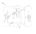
- FIG. FIG. 5 is a schematic configuration diagram showing an example of a refrigerant circuit configuration of a refrigeration cycle apparatus (hereinafter referred to as refrigeration cycle apparatus 100B) according to Embodiment 2 of the present invention.
- FIG. 6 is a schematic configuration diagram showing another example of the refrigerant circuit configuration of the refrigeration cycle apparatus 100B.
- FIG. 7 is a schematic configuration diagram showing still another example of the refrigerant circuit configuration of the refrigeration cycle apparatus 100B.
- FIG. 8 is a schematic configuration diagram showing still another example of the refrigerant circuit configuration of the refrigeration cycle apparatus 100B.
- the refrigeration cycle apparatus 100B will be described with reference to FIGS. In the second embodiment, differences from the first embodiment will be mainly described, and the same parts as those in the first embodiment will be denoted by the same reference numerals and description thereof will be omitted.
- the basic configuration of the refrigeration cycle apparatus 100B is the same as that of the refrigeration cycle apparatus 100A according to Embodiment 1.
- Embodiment 1 although the example which connected the piping 15 to the shell of the compressor 3 was shown, in Embodiment 2, the piping 15 is connected to the discharge piping 3a of the compressor 3.
- FIG. A refrigerant having a high temperature and a high pressure flows through the discharge pipe 3a. Therefore, the refrigerant is quickly discharged from the high-pressure discharge pipe 3a.
- Other configurations of the refrigeration cycle apparatus 100B are the same as those of the refrigeration cycle apparatus 100A according to the first embodiment.
- the refrigerant used for the refrigeration cycle apparatus 100B is the same as that of the refrigeration cycle apparatus 100A according to Embodiment 1.
- ⁇ Refrigerating means shown in FIG. 5> In the refrigeration cycle apparatus 100B shown in FIG. 5, one end side of the pipe 15 (the end side that is not the discharge pipe 3a side end) is positioned outside the outdoor unit 1, and the valve 10 is installed there. The valve 10 is controlled to be opened and closed by the control device 30 as described in the first embodiment.
- the refrigerant mainly composed of HFO-1123 is released to the outside of the outdoor unit 1 to disproportionately.
- the chemical reaction can be prevented.
- the conditions for opening the valve 10 are as described in the first embodiment.
- one end side of the pipe 15 (the end side that is not the end part on the discharge pipe 3a side) is configured with the branch pipe 11 having a smaller diameter than the liquid pipe 7 and the gas pipe 9, It is located outside the outdoor unit 1 with its one end side closed.
- the branch pipe 11 is broken at a predetermined pressure or a predetermined temperature.
- the refrigerant mainly composed of HFO-1123 is released to the outside of the outdoor unit 1 to disproportionately.
- the chemical reaction can be prevented.
- the conditions for breaking the branch pipe 11 are as described in the first embodiment.
- one end side of the pipe 15 (the end side which is not the discharge pipe 3a side end) is constituted by the branch pipe 11 having a smaller diameter than the liquid pipe 7 and the gas pipe 9.
- the one end side is positioned outside the outdoor unit 1 with the cap 12 closed.
- the cap 12 is configured to come off or break at a predetermined pressure or a predetermined temperature.
- the refrigerant containing HFO-1123 as a main component is released to the atmosphere outside the outdoor unit 1 to disproportionately.
- the chemical reaction can be prevented.
- the conditions for removing or breaking the cap 12 are as described in the first embodiment.
- ⁇ Refrigerant release means shown in FIG. 8> In the refrigeration cycle apparatus 100B shown in FIG. 8, one end side of the pipe 15 (the end side that is not the end on the discharge pipe 3a side) is positioned outside the outdoor unit 1, and the valve 10 is installed there. A branch pipe 11 having a diameter smaller than that of the liquid pipe 7 and the gas pipe 9 is connected to one end side (the end portion side which is not the discharge pipe 3a side end portion) via a flare nut 13.
- the valve 10 is controlled to be opened and closed by the control device 30 as described in the first embodiment. As described in the first embodiment, the branch pipe 11 is broken at a predetermined pressure or a predetermined temperature. In addition, you may make it provide the cap 12 shown in FIG.
- the refrigerant mainly composed of HFO-1123 is released to the outside of the outdoor unit 1 to disproportionately.
- the chemical reaction can be prevented.
- the refrigerant is not opened as long as the branch pipe 11 is not broken, and serviceability is improved.
- the conditions for opening the valve 10 and the conditions for breaking the branch pipe 11 are as described in the first embodiment.
- the blockage of the pipe 15 after the branch pipe 11 is broken is also as described in the first embodiment.
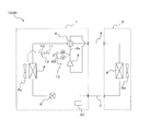
- FIG. 9 is a schematic configuration diagram showing an example of a refrigerant circuit configuration of a refrigeration cycle apparatus (hereinafter referred to as refrigeration cycle apparatus 100C) according to Embodiment 3 of the present invention.
- FIG. 10 is a schematic configuration diagram illustrating another example of the refrigerant circuit configuration of the refrigeration cycle apparatus 100C.
- FIG. 11 is a schematic configuration diagram illustrating still another example of the refrigerant circuit configuration of the refrigeration cycle apparatus 100C.
- FIG. 12 is a schematic configuration diagram showing still another example of the refrigerant circuit configuration of the refrigeration cycle apparatus 100C.
- the refrigeration cycle apparatus 100C will be described with reference to FIGS.
- differences from the first and second embodiments will be mainly described, and the same parts as those in the first and second embodiments will be denoted by the same reference numerals and the description thereof will be omitted.
- the basic configuration of the refrigeration cycle apparatus 100C is the same as that of the refrigeration cycle apparatus 100A according to the first embodiment.
- the pipe 15 is connected to the shell of the compressor 3
- the pipe 15 is connected to the gas pipe 9.
- Other configurations of the refrigeration cycle apparatus 100C are the same as those of the refrigeration cycle apparatus 100A according to Embodiment 1.
- the refrigerant used for the refrigeration cycle apparatus 100C is the same as that of the refrigeration cycle apparatus 100A according to the first embodiment.
- ⁇ Refrigerating means shown in FIG. 9> In the refrigeration cycle apparatus 100C shown in FIG. 9, one end side of the pipe 15 (the end side that is not the end portion on the gas pipe 9 side) is positioned outside the outdoor unit 1, and the valve 10 is installed there. The valve 10 is controlled to be opened and closed by the control device 30 as described in the first embodiment.
- the refrigerant mainly composed of HFO-1123 is released to the outside of the outdoor unit 1 to disproportionately.
- the chemical reaction can be prevented.
- the conditions for opening the valve 10 are as described in the first embodiment.
- one end side of the pipe 15 (the end side that is not the gas pipe 9 side end) is configured with the liquid pipe 7 and the branch pipe 11 having a smaller diameter than the gas pipe 9. It is located outside the outdoor unit 1 with its one end side closed. As described in the first embodiment, the branch pipe 11 is broken at a predetermined pressure or a predetermined temperature.
- the refrigerant mainly composed of HFO-1123 is released to the outside of the outdoor unit 1 to disproportionately.
- the chemical reaction can be prevented.
- the conditions for breaking the branch pipe 11 are as described in the first embodiment.
- one end side of the pipe 15 (the end side that is not the gas pipe 9 side end) is constituted by the liquid pipe 7 and the branch pipe 11 having a smaller diameter than the gas pipe 9.
- the one end side is positioned outside the outdoor unit 1 with the cap 12 closed.
- the cap 12 is configured to come off or break at a predetermined pressure or a predetermined temperature.
- the refrigerant containing HFO-1123 as a main component is released to the atmosphere outside the outdoor unit 1 to disproportionately.
- the chemical reaction can be prevented.
- the conditions for removing or breaking the cap 12 are as described in the first embodiment.
- ⁇ Refrigerant release means shown in FIG. 12> In the refrigeration cycle apparatus 100C shown in FIG. 12, one end side of the pipe 15 (the end side that is not the gas pipe 9 side end) is positioned outside the outdoor unit 1, and the valve 10 is installed there. A branch pipe 11 having a diameter smaller than that of the liquid pipe 7 and the gas pipe 9 is connected to one end side (the end side which is not the gas pipe 9 side end) via a flare nut 13.
- the valve 10 is controlled to be opened and closed by the control device 30 as described in the first embodiment. As described in the first embodiment, the branch pipe 11 is broken at a predetermined pressure or a predetermined temperature. In addition, you may make it provide the cap 12 shown in FIG.
- the refrigerant mainly composed of HFO-1123 is released to the outside of the outdoor unit 1 to disproportionately.
- the chemical reaction can be prevented.
- the refrigerant is not opened as long as the branch pipe 11 is not broken, and serviceability is improved.
- the conditions for opening the valve 10 and the conditions for breaking the branch pipe 11 are as described in the first embodiment.
- the blockage of the pipe 15 after the branch pipe 11 is broken is also as described in the first embodiment.
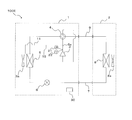
- FIG. 13 is a schematic configuration diagram showing an example of a refrigerant circuit configuration of a refrigeration cycle apparatus (hereinafter referred to as refrigeration cycle apparatus 100D) according to Embodiment 4 of the present invention.
- FIG. 14 is a schematic configuration diagram illustrating another example of the refrigerant circuit configuration of the refrigeration cycle apparatus 100D.
- FIG. 15 is a schematic configuration diagram showing still another example of the refrigerant circuit configuration of the refrigeration cycle apparatus 100D.
- FIG. 16 is a schematic configuration diagram showing still another example of the refrigerant circuit configuration of the refrigeration cycle apparatus 100D.
- the refrigeration cycle apparatus 100D will be described based on FIGS.
- differences from the first to third embodiments will be mainly described, and the same parts as those in the first to third embodiments will be denoted by the same reference numerals and the description thereof will be omitted.
- the basic configuration of the refrigeration cycle apparatus 100D is the same as that of the refrigeration cycle apparatus 100A according to the first embodiment.
- the example in which one of the pipes 15 is connected to the shell of the compressor 3 and the other of the pipes 15 is positioned outside the outdoor unit 1 is shown. Is connected to the shell of the compressor 3, and the other side of the pipe 15 is positioned on the suction side of the outdoor fan 5a.
- Other configurations of the refrigeration cycle apparatus 100D are the same as those of the refrigeration cycle apparatus 100A according to Embodiment 1.
- the refrigerant used for the refrigeration cycle apparatus 100D is the same as that of the refrigeration cycle apparatus 100A according to the first embodiment.
- ⁇ Refrigerating means shown in FIG. 13> In the refrigeration cycle apparatus 100D shown in FIG. 13, one end side of the pipe 15 (the end side that is not the end portion on the compressor 3 side) is positioned on the suction side of the outdoor fan 5a, and the valve 10 is installed there. . And the control apparatus 30 operates the outdoor air blower 5a, when the valve
- the refrigerant mainly composed of HFO-1123 is discharged to the outside of the refrigeration cycle, and is supplied to the outdoor unit 1.
- the disproportionation reaction can be prevented by quickly releasing the air using the outdoor fan 5a accommodated.
- the conditions for opening the valve 10 are as described in the first embodiment.
- one end side of the pipe 15 (the end side that is not the end portion on the compressor 3 side) is configured by the branch pipe 11 having a smaller diameter than the liquid pipe 7 and the gas pipe 9. With the one end side closed, the outdoor blower 5a is positioned on the suction side. And the control apparatus 30 operates the outdoor air blower 5a, when the branch pipe 11 is destroyed.
- the branch pipe 11 is broken at a predetermined pressure or a predetermined temperature. Whether or not the branch pipe 11 is broken may be estimated based on measured values of the pressure detector 21 and the temperature detector 22, for example.
- the refrigerant mainly composed of HFO-1123 is discharged to the outside of the refrigeration cycle and is supplied to the outdoor unit 1.
- the disproportionation reaction can be prevented by quickly releasing the air using the outdoor fan 5a accommodated.
- the conditions for breaking the branch pipe 11 are as described in the first embodiment.
- one end side of the pipe 15 (the end side that is not the end portion on the compressor 3 side) is configured by the branch pipe 11 having a smaller diameter than the liquid pipe 7 and the gas pipe 9.
- the one end side is located on the suction side of the outdoor fan 5a with the cap 12 closed.
- the control apparatus 30 operates the outdoor air blower 5a, when the cap 12 remove
- the cap 12 is configured to come off or break at a predetermined pressure or a predetermined temperature. Whether the cap 12 has been removed or broken can be estimated from, for example, measured values of the pressure detector 21 and the temperature detector 22.
- the refrigerant mainly composed of HFO-1123 is discharged to the outside of the refrigeration cycle and is supplied to the outdoor unit 1.
- the disproportionation reaction can be prevented by quickly releasing the air using the outdoor fan 5a accommodated.
- the conditions for removing or breaking the cap 12 are as described in the first embodiment.
- ⁇ Refrigerating means shown in FIG. 16> In the refrigeration cycle apparatus 100D shown in FIG. 16, one end side of the pipe 15 (the end side that is not the end portion on the compressor 3 side) is positioned on the suction side of the outdoor fan 5a, and the valve 10 is installed there.
- a branch pipe 11 having a diameter smaller than that of the liquid pipe 7 and the gas pipe 9 is connected to one end side of the pipe 10 (the end side which is not the end portion on the compressor 3 side) via a flare nut 13.
- the control apparatus 30 operates the outdoor air blower 5a, when the branch pipe 11 is destroyed.
- the valve 10 is controlled to be opened and closed by the control device 30 as described in the first embodiment.
- the branch pipe 11 is broken at a predetermined pressure or a predetermined temperature.
- the refrigerant mainly composed of HFO-1123 is discharged to the outside of the refrigeration cycle, and the outdoor unit 1
- the disproportionation reaction can be prevented by quickly releasing the air using the outdoor fan 5a accommodated.
- the valve 10 is opened by mistake, the refrigerant is not opened as long as the branch pipe 11 is not broken, and serviceability is improved.
- the conditions for opening the valve 10 and the conditions for breaking the branch pipe 11 are as described in the first embodiment.
- the blockage of the pipe 15 after the branch pipe 11 is broken is also as described in the first embodiment.
- FIG. 17 is a schematic configuration diagram showing an example of a refrigerant circuit configuration of a refrigeration cycle apparatus (hereinafter referred to as refrigeration cycle apparatus 100E) according to Embodiment 5 of the present invention.
- FIG. 18 is a schematic configuration diagram illustrating another example of the refrigerant circuit configuration of the refrigeration cycle apparatus 100E.
- FIG. 19 is a schematic configuration diagram showing still another example of the refrigerant circuit configuration of the refrigeration cycle apparatus 100E.
- FIG. 20 is a schematic configuration diagram illustrating still another example of the refrigerant circuit configuration of the refrigeration cycle apparatus 100E.
- the refrigeration cycle apparatus 100E will be described with reference to FIGS.
- differences from the first to fourth embodiments will be mainly described, and the same parts as those in the first to fourth embodiments will be denoted by the same reference numerals and description thereof will be omitted.
- the basic configuration of the refrigeration cycle apparatus 100E is the same as that of the refrigeration cycle apparatus 100A according to Embodiment 1.
- the example in which one of the pipes 15 is connected to the shell of the compressor 3 and the other of the pipes 15 is positioned outside the outdoor unit 1 is shown. Is connected to the discharge pipe 3a of the compressor 3, and the other of the pipes 15 is positioned on the suction side of the outdoor fan 5a.
- the other configuration of the refrigeration cycle apparatus 100E is the same as that of the refrigeration cycle apparatus 100A according to Embodiment 1.
- the refrigerant used for the refrigeration cycle apparatus 100E is the same as that of the refrigeration cycle apparatus 100A according to the first embodiment.
- ⁇ Refrigerant release means shown in FIG. 17> In the refrigeration cycle apparatus 100E shown in FIG. 17, one end side of the pipe 15 (the end side that is not the end part on the discharge pipe 3a side) is positioned on the suction side of the outdoor fan 5a, and the valve 10 is installed there. . The valve 10 is controlled to be opened and closed by the control device 30 as described in the first embodiment.
- the refrigerant mainly composed of HFO-1123 is discharged to the outside of the refrigeration cycle, and the outdoor unit 1
- the disproportionation reaction can be prevented by quickly releasing the air using the outdoor fan 5a accommodated.
- the conditions for opening the valve 10 are as described in the first embodiment.
- one end side of the pipe 15 (the end side which is not the discharge pipe 3a side end) is configured with the branch pipe 11 having a smaller diameter than the liquid pipe 7 and the gas pipe 9. With the one end side closed, the outdoor blower 5a is positioned on the suction side. As described in the first embodiment, the branch pipe 11 is broken at a predetermined pressure or a predetermined temperature.
- the refrigerant mainly composed of HFO-1123 is discharged to the outside of the refrigeration cycle, and the outdoor unit 1
- the disproportionation reaction can be prevented by quickly releasing the air using the outdoor fan 5a accommodated.
- the conditions for breaking the branch pipe 11 are as described in the first embodiment.
- one end side of the pipe 15 (the end side that is not the discharge pipe 3a side end) is configured with the branch pipe 11 having a smaller diameter than the liquid pipe 7 and the gas pipe 9.
- the one end side is located on the suction side of the outdoor fan 5a with the cap 12 closed.
- the cap 12 is configured to come off or break at a predetermined pressure or a predetermined temperature.
- the refrigerant mainly composed of HFO-1123 is discharged to the outside of the refrigeration cycle, and the outdoor unit 1
- the disproportionation reaction can be prevented by quickly releasing the air using the outdoor fan 5a accommodated.
- the conditions for removing or breaking the cap 12 are as described in the first embodiment.
- ⁇ Refrigerant release means shown in FIG. 20> In the refrigeration cycle apparatus 100E shown in FIG. 20, one end side of the pipe 15 (the end side that is not the end part on the discharge pipe 3a side) is positioned on the suction side of the outdoor fan 5a, and the valve 10 is installed there.
- a branch pipe 11 having a diameter smaller than that of the liquid pipe 7 and the gas pipe 9 is connected to one end side of the pipe 10 (the end part side which is not the discharge pipe 3a side end part) via a flare nut 13.
- the valve 10 is controlled to be opened and closed by the control device 30 as described in the first embodiment. As described in the first embodiment, the branch pipe 11 is broken at a predetermined pressure or a predetermined temperature. In addition, you may make it provide the cap 12 shown in FIG.
- the refrigerant mainly composed of HFO-1123 is discharged to the outside of the refrigeration cycle, and the outdoor unit 1
- the disproportionation reaction can be prevented by quickly releasing the air using the outdoor fan 5a accommodated.
- the valve 10 is opened by mistake, the refrigerant is not opened as long as the branch pipe 11 is not broken, and serviceability is improved.
- the conditions for opening the valve 10 and the conditions for breaking the branch pipe 11 are as described in the first embodiment.
- the blockage of the pipe 15 after the branch pipe 11 is broken is also as described in the first embodiment.
- the refrigeration cycle apparatus has been described in five embodiments. However, the present invention is not limited to these embodiments, and various modifications or changes can be made without departing from the scope and spirit of the present invention.
- the case where one pipe 15 is connected has been described as an example, but a plurality of pipes 15 may be connected.
- a pipe 15 may be further connected between the outdoor heat exchanger 5 and the four-way valve 4.
- the gas pipe 9 may be substituted for the pipe 15.
- the gas pipe 9 connecting the outdoor unit 1 and the indoor unit 2 is connected via a connection valve composed of a three-way valve or the like.
- one end of the connection valve is attached with a service port that is used for evacuation (before the refrigerant is supplied to the refrigerant circuit).
- the gas pipe 9 leading to the service port may be used as a substitute for the pipe 15.
- a refrigerant mainly composed of HFO-1123 when discharged to the outside of the refrigeration cycle, it is preferable to be able to issue an alarm by at least one of display and sound. If it does in this way, a user can be alert
- a remote control installed corresponding to the indoor unit 2 or a display of a PC or portable information terminal (cell phone, smartphone, etc.) when connected by a network. Good.
- issuing a report by voice it is preferable to report by a buzzer sound or voice by language.
- the refrigeration cycle apparatus described in each embodiment is applied to an apparatus equipped with a refrigeration cycle, such as an air conditioner (for example, a refrigeration apparatus, a room air conditioner, a packaged air conditioner, a multi air conditioner for buildings), a heat pump water heater, and the like. Can be used.
- a refrigeration cycle such as an air conditioner (for example, a refrigeration apparatus, a room air conditioner, a packaged air conditioner, a multi air conditioner for buildings), a heat pump water heater, and the like. Can be used.
Landscapes
- Engineering & Computer Science (AREA)
- Physics & Mathematics (AREA)
- Mechanical Engineering (AREA)
- Thermal Sciences (AREA)
- General Engineering & Computer Science (AREA)
- Air Conditioning Control Device (AREA)
Abstract
La présente invention concerne un dispositif à cycle de réfrigération permettant d'assurer une sécurité adéquate même lorsqu'un réfrigérant qui a comme propriété de provoquer une réaction de dismutation est utilisé en tant que composant principal. Ce dispositif à cycle de réfrigération comprend un circuit de refroidissement dans lequel au moins un compresseur (3), un premier échangeur de chaleur (5), un mécanisme de réduction de pression (6), et un second échangeur de chaleur (8) sont raccordés, un réfrigérant qui a comme propriété de provoquer une réaction de dismutation étant utilisé en tant que composant principal dans le circuit de refroidissement. Lorsque la pression et/ou la température du réfrigérant dans le circuit de refroidissement s'approchent respectivement d'une pression limite et/ou d'une température limite à laquelle/auxquelles le réfrigérant provoque une réaction de dismutation, le réfrigérant est évacué du circuit de refroidissement.
Priority Applications (2)
| Application Number | Priority Date | Filing Date | Title |
|---|---|---|---|
| PCT/JP2014/057034 WO2015140876A1 (fr) | 2014-03-17 | 2014-03-17 | Dispositif à cycle de réfrigération |
| JP2016508336A JP6223546B2 (ja) | 2014-03-17 | 2014-03-17 | 冷凍サイクル装置 |
Applications Claiming Priority (1)
| Application Number | Priority Date | Filing Date | Title |
|---|---|---|---|
| PCT/JP2014/057034 WO2015140876A1 (fr) | 2014-03-17 | 2014-03-17 | Dispositif à cycle de réfrigération |
Publications (1)
| Publication Number | Publication Date |
|---|---|
| WO2015140876A1 true WO2015140876A1 (fr) | 2015-09-24 |
Family
ID=54143902
Family Applications (1)
| Application Number | Title | Priority Date | Filing Date |
|---|---|---|---|
| PCT/JP2014/057034 Ceased WO2015140876A1 (fr) | 2014-03-17 | 2014-03-17 | Dispositif à cycle de réfrigération |
Country Status (2)
| Country | Link |
|---|---|
| JP (1) | JP6223546B2 (fr) |
| WO (1) | WO2015140876A1 (fr) |
Cited By (15)
| Publication number | Priority date | Publication date | Assignee | Title |
|---|---|---|---|---|
| WO2017168503A1 (fr) * | 2016-03-28 | 2017-10-05 | 三菱電機株式会社 | Unité extérieure |
| WO2017179117A1 (fr) * | 2016-04-12 | 2017-10-19 | 三菱電機株式会社 | Climatiseur |
| JP2018025326A (ja) * | 2016-08-09 | 2018-02-15 | パナソニックIpマネジメント株式会社 | 冷凍サイクル装置 |
| JP2018096652A (ja) * | 2016-12-16 | 2018-06-21 | パナソニックIpマネジメント株式会社 | 冷凍サイクル装置 |
| WO2018139589A1 (fr) * | 2017-01-30 | 2018-08-02 | ダイキン工業株式会社 | Dispositif de réfrigération |
| WO2018193974A1 (fr) * | 2017-04-20 | 2018-10-25 | Agc株式会社 | Système à cycle thermodynamique |
| WO2019027050A1 (fr) * | 2017-08-03 | 2019-02-07 | ダイキン工業株式会社 | Dispositif frigorifique |
| JP2019027655A (ja) * | 2017-07-28 | 2019-02-21 | パナソニックIpマネジメント株式会社 | 冷凍サイクル装置 |
| JP2019027654A (ja) * | 2017-07-28 | 2019-02-21 | パナソニックIpマネジメント株式会社 | 冷凍サイクル装置 |
| JPWO2018181038A1 (ja) * | 2017-03-31 | 2020-01-23 | ダイキン工業株式会社 | 空気調和装置 |
| JP2020046173A (ja) * | 2019-12-24 | 2020-03-26 | 三菱電機株式会社 | 室外機及び冷凍サイクル装置 |
| JP2020153557A (ja) * | 2019-03-19 | 2020-09-24 | サンデンホールディングス株式会社 | 空気調和装置 |
| EP3575709A4 (fr) * | 2017-01-30 | 2020-12-02 | Daikin Industries, Ltd. | Dispositif de réfrigération |
| WO2022044219A1 (fr) * | 2020-08-27 | 2022-03-03 | 三菱電機株式会社 | Dispositif à cycle de réfrigération |
| WO2025069310A1 (fr) * | 2023-09-28 | 2025-04-03 | ダイキン工業株式会社 | Dispositif à cycle frigorifique |
Citations (9)
| Publication number | Priority date | Publication date | Assignee | Title |
|---|---|---|---|---|
| JPH09324965A (ja) * | 1996-06-05 | 1997-12-16 | Calsonic Corp | 可溶栓付きチャージバルブ及びこれを備えたリキッドタンク並びに冷房サイクル |
| JP2001071741A (ja) * | 1999-09-02 | 2001-03-21 | Zexel Valeo Climate Control Corp | 車両用空調装置 |
| JP2007005034A (ja) * | 2005-06-21 | 2007-01-11 | Ubukata Industries Co Ltd | 温度・圧力保護装置 |
| JP2007232343A (ja) * | 2006-02-02 | 2007-09-13 | Sanden Corp | 冷凍回路及び圧縮機 |
| JP2009103363A (ja) * | 2007-10-23 | 2009-05-14 | Daikin Ind Ltd | 受液器及びそれを備えた冷凍装置 |
| JP2010078285A (ja) * | 2008-09-29 | 2010-04-08 | Mitsubishi Electric Corp | ヒートポンプ給湯機 |
| JP2012131994A (ja) * | 2010-11-30 | 2012-07-12 | Jx Nippon Oil & Energy Corp | 冷凍機用作動流体組成物および冷凍機油 |
| WO2012157764A1 (fr) * | 2011-05-19 | 2012-11-22 | 旭硝子株式会社 | Fluide moteur, et système à cycle thermique |
| WO2013051271A1 (fr) * | 2011-10-06 | 2013-04-11 | パナソニック株式会社 | Dispositif de réfrigération |
-
2014
- 2014-03-17 WO PCT/JP2014/057034 patent/WO2015140876A1/fr not_active Ceased
- 2014-03-17 JP JP2016508336A patent/JP6223546B2/ja active Active
Patent Citations (9)
| Publication number | Priority date | Publication date | Assignee | Title |
|---|---|---|---|---|
| JPH09324965A (ja) * | 1996-06-05 | 1997-12-16 | Calsonic Corp | 可溶栓付きチャージバルブ及びこれを備えたリキッドタンク並びに冷房サイクル |
| JP2001071741A (ja) * | 1999-09-02 | 2001-03-21 | Zexel Valeo Climate Control Corp | 車両用空調装置 |
| JP2007005034A (ja) * | 2005-06-21 | 2007-01-11 | Ubukata Industries Co Ltd | 温度・圧力保護装置 |
| JP2007232343A (ja) * | 2006-02-02 | 2007-09-13 | Sanden Corp | 冷凍回路及び圧縮機 |
| JP2009103363A (ja) * | 2007-10-23 | 2009-05-14 | Daikin Ind Ltd | 受液器及びそれを備えた冷凍装置 |
| JP2010078285A (ja) * | 2008-09-29 | 2010-04-08 | Mitsubishi Electric Corp | ヒートポンプ給湯機 |
| JP2012131994A (ja) * | 2010-11-30 | 2012-07-12 | Jx Nippon Oil & Energy Corp | 冷凍機用作動流体組成物および冷凍機油 |
| WO2012157764A1 (fr) * | 2011-05-19 | 2012-11-22 | 旭硝子株式会社 | Fluide moteur, et système à cycle thermique |
| WO2013051271A1 (fr) * | 2011-10-06 | 2013-04-11 | パナソニック株式会社 | Dispositif de réfrigération |
Cited By (34)
| Publication number | Priority date | Publication date | Assignee | Title |
|---|---|---|---|---|
| US11105521B2 (en) | 2016-03-28 | 2021-08-31 | Mitsubishi Electric Corporation | Outdoor unit |
| WO2017168503A1 (fr) * | 2016-03-28 | 2017-10-05 | 三菱電機株式会社 | Unité extérieure |
| JPWO2017168503A1 (ja) * | 2016-03-28 | 2018-11-22 | 三菱電機株式会社 | 室外機 |
| WO2017179117A1 (fr) * | 2016-04-12 | 2017-10-19 | 三菱電機株式会社 | Climatiseur |
| JP2018025326A (ja) * | 2016-08-09 | 2018-02-15 | パナソニックIpマネジメント株式会社 | 冷凍サイクル装置 |
| JP2018096652A (ja) * | 2016-12-16 | 2018-06-21 | パナソニックIpマネジメント株式会社 | 冷凍サイクル装置 |
| EP3575709A4 (fr) * | 2017-01-30 | 2020-12-02 | Daikin Industries, Ltd. | Dispositif de réfrigération |
| JP2018123971A (ja) * | 2017-01-30 | 2018-08-09 | ダイキン工業株式会社 | 冷凍装置 |
| WO2018139589A1 (fr) * | 2017-01-30 | 2018-08-02 | ダイキン工業株式会社 | Dispositif de réfrigération |
| EP3575713A4 (fr) * | 2017-01-30 | 2020-12-02 | Daikin Industries, Ltd. | Dispositif de réfrigération |
| US11143446B2 (en) | 2017-01-30 | 2021-10-12 | Daikin Industries, Ltd. | Refrigeration device controlling a temperature of compressor-discharged refrigerant |
| CN110268208A (zh) * | 2017-01-30 | 2019-09-20 | 大金工业株式会社 | 冷冻装置 |
| JP7001346B2 (ja) | 2017-01-30 | 2022-01-19 | ダイキン工業株式会社 | 冷凍装置 |
| US11326819B2 (en) | 2017-01-30 | 2022-05-10 | Daikin Industries, Ltd. | Refrigeration apparatus |
| JPWO2018181038A1 (ja) * | 2017-03-31 | 2020-01-23 | ダイキン工業株式会社 | 空気調和装置 |
| JP7151704B2 (ja) | 2017-04-20 | 2022-10-12 | Agc株式会社 | 熱サイクルシステム |
| JPWO2018193974A1 (ja) * | 2017-04-20 | 2020-02-27 | Agc株式会社 | 熱サイクルシステム |
| CN110537062A (zh) * | 2017-04-20 | 2019-12-03 | Agc株式会社 | 热循环系统 |
| WO2018193974A1 (fr) * | 2017-04-20 | 2018-10-25 | Agc株式会社 | Système à cycle thermodynamique |
| EP3614076A4 (fr) * | 2017-04-20 | 2021-01-06 | AGC Inc. | Système à cycle thermodynamique |
| US11009269B2 (en) | 2017-04-20 | 2021-05-18 | AGC Inc. | Heat cycle system |
| JP2019027654A (ja) * | 2017-07-28 | 2019-02-21 | パナソニックIpマネジメント株式会社 | 冷凍サイクル装置 |
| JP2019027655A (ja) * | 2017-07-28 | 2019-02-21 | パナソニックIpマネジメント株式会社 | 冷凍サイクル装置 |
| WO2019027050A1 (fr) * | 2017-08-03 | 2019-02-07 | ダイキン工業株式会社 | Dispositif frigorifique |
| JP7032667B2 (ja) | 2017-08-03 | 2022-03-09 | ダイキン工業株式会社 | 冷凍装置 |
| JPWO2019027050A1 (ja) * | 2017-08-03 | 2020-07-02 | ダイキン工業株式会社 | 冷凍装置 |
| WO2020189489A1 (fr) * | 2019-03-19 | 2020-09-24 | サンデンホールディングス株式会社 | Dispositif de climatisation |
| CN113557398A (zh) * | 2019-03-19 | 2021-10-26 | 三电控股株式会社 | 空调装置 |
| JP2020153557A (ja) * | 2019-03-19 | 2020-09-24 | サンデンホールディングス株式会社 | 空気調和装置 |
| JP2020046173A (ja) * | 2019-12-24 | 2020-03-26 | 三菱電機株式会社 | 室外機及び冷凍サイクル装置 |
| WO2022044219A1 (fr) * | 2020-08-27 | 2022-03-03 | 三菱電機株式会社 | Dispositif à cycle de réfrigération |
| JPWO2022044219A1 (fr) * | 2020-08-27 | 2022-03-03 | ||
| JP7357804B2 (ja) | 2020-08-27 | 2023-10-06 | 三菱電機株式会社 | 冷凍サイクル装置 |
| WO2025069310A1 (fr) * | 2023-09-28 | 2025-04-03 | ダイキン工業株式会社 | Dispositif à cycle frigorifique |
Also Published As
| Publication number | Publication date |
|---|---|
| JP6223546B2 (ja) | 2017-11-01 |
| JPWO2015140876A1 (ja) | 2017-04-06 |
Similar Documents
| Publication | Publication Date | Title |
|---|---|---|
| JP6223546B2 (ja) | 冷凍サイクル装置 | |
| JP5818900B2 (ja) | ヒートポンプ装置 | |
| JP7032667B2 (ja) | 冷凍装置 | |
| CN104603557B (zh) | 制冷装置 | |
| US11209195B2 (en) | Air conditioner with a refrigerant having a property of undergoing disproportionation | |
| US10126026B2 (en) | Refrigeration cycle apparatus | |
| WO2015140874A1 (fr) | Dispositif de climatisation | |
| JP5908183B1 (ja) | 空気調和装置 | |
| WO2016071955A1 (fr) | Appareil de climatisation | |
| US11112154B2 (en) | Air conditioner | |
| US11326819B2 (en) | Refrigeration apparatus | |
| JP6188916B2 (ja) | 冷凍サイクル装置 | |
| JP2018173196A5 (fr) | ||
| WO2022050351A1 (fr) | Utilisation de fluide frigorigène dans un appareil à cycle de réfrigération et appareil à cycle de réfrigération | |
| JP2018059638A (ja) | 熱交換器および冷凍サイクル装置 | |
| JP2009103363A (ja) | 受液器及びそれを備えた冷凍装置 | |
| WO2018042490A1 (fr) | Dispositif à cycle de réfrigération | |
| JP2022150675A (ja) | ヒートポンプ装置 |
Legal Events
| Date | Code | Title | Description |
|---|---|---|---|
| 121 | Ep: the epo has been informed by wipo that ep was designated in this application |
Ref document number: 14886520 Country of ref document: EP Kind code of ref document: A1 |
|
| ENP | Entry into the national phase |
Ref document number: 2016508336 Country of ref document: JP Kind code of ref document: A |
|
| NENP | Non-entry into the national phase |
Ref country code: DE |
|
| 122 | Ep: pct application non-entry in european phase |
Ref document number: 14886520 Country of ref document: EP Kind code of ref document: A1 |