WO2015141226A1 - 電子デバイス - Google Patents
電子デバイス Download PDFInfo
- Publication number
- WO2015141226A1 WO2015141226A1 PCT/JP2015/001529 JP2015001529W WO2015141226A1 WO 2015141226 A1 WO2015141226 A1 WO 2015141226A1 JP 2015001529 W JP2015001529 W JP 2015001529W WO 2015141226 A1 WO2015141226 A1 WO 2015141226A1
- Authority
- WO
- WIPO (PCT)
- Prior art keywords
- layer
- group
- quantum dot
- electronic device
- ion
- Prior art date
- Legal status (The legal status is an assumption and is not a legal conclusion. Google has not performed a legal analysis and makes no representation as to the accuracy of the status listed.)
- Ceased
Links
Images


Classifications
-
- C—CHEMISTRY; METALLURGY
- C09—DYES; PAINTS; POLISHES; NATURAL RESINS; ADHESIVES; COMPOSITIONS NOT OTHERWISE PROVIDED FOR; APPLICATIONS OF MATERIALS NOT OTHERWISE PROVIDED FOR
- C09D—COATING COMPOSITIONS, e.g. PAINTS, VARNISHES OR LACQUERS; FILLING PASTES; CHEMICAL PAINT OR INK REMOVERS; INKS; CORRECTING FLUIDS; WOODSTAINS; PASTES OR SOLIDS FOR COLOURING OR PRINTING; USE OF MATERIALS THEREFOR
- C09D7/00—Features of coating compositions, not provided for in group C09D5/00; Processes for incorporating ingredients in coating compositions
- C09D7/40—Additives
- C09D7/60—Additives non-macromolecular
- C09D7/61—Additives non-macromolecular inorganic
-
- H—ELECTRICITY
- H10—SEMICONDUCTOR DEVICES; ELECTRIC SOLID-STATE DEVICES NOT OTHERWISE PROVIDED FOR
- H10H—INORGANIC LIGHT-EMITTING SEMICONDUCTOR DEVICES HAVING POTENTIAL BARRIERS
- H10H20/00—Individual inorganic light-emitting semiconductor devices having potential barriers, e.g. light-emitting diodes [LED]
- H10H20/80—Constructional details
- H10H20/85—Packages
- H10H20/852—Encapsulations
- H10H20/854—Encapsulations characterised by their material, e.g. epoxy or silicone resins
-
- B—PERFORMING OPERATIONS; TRANSPORTING
- B32—LAYERED PRODUCTS
- B32B—LAYERED PRODUCTS, i.e. PRODUCTS BUILT-UP OF STRATA OF FLAT OR NON-FLAT, e.g. CELLULAR OR HONEYCOMB, FORM
- B32B23/00—Layered products comprising a layer of cellulosic plastic substances, i.e. substances obtained by chemical modification of cellulose, e.g. cellulose ethers, cellulose esters, viscose
- B32B23/04—Layered products comprising a layer of cellulosic plastic substances, i.e. substances obtained by chemical modification of cellulose, e.g. cellulose ethers, cellulose esters, viscose comprising such cellulosic plastic substance as the main or only constituent of a layer, which is next to another layer of the same or of a different material
- B32B23/08—Layered products comprising a layer of cellulosic plastic substances, i.e. substances obtained by chemical modification of cellulose, e.g. cellulose ethers, cellulose esters, viscose comprising such cellulosic plastic substance as the main or only constituent of a layer, which is next to another layer of the same or of a different material of synthetic resin
-
- B—PERFORMING OPERATIONS; TRANSPORTING
- B32—LAYERED PRODUCTS
- B32B—LAYERED PRODUCTS, i.e. PRODUCTS BUILT-UP OF STRATA OF FLAT OR NON-FLAT, e.g. CELLULAR OR HONEYCOMB, FORM
- B32B27/00—Layered products comprising a layer of synthetic resin
-
- B—PERFORMING OPERATIONS; TRANSPORTING
- B32—LAYERED PRODUCTS
- B32B—LAYERED PRODUCTS, i.e. PRODUCTS BUILT-UP OF STRATA OF FLAT OR NON-FLAT, e.g. CELLULAR OR HONEYCOMB, FORM
- B32B27/00—Layered products comprising a layer of synthetic resin
- B32B27/06—Layered products comprising a layer of synthetic resin as the main or only constituent of a layer, which is next to another layer of the same or of a different material
- B32B27/08—Layered products comprising a layer of synthetic resin as the main or only constituent of a layer, which is next to another layer of the same or of a different material of synthetic resin
-
- B—PERFORMING OPERATIONS; TRANSPORTING
- B32—LAYERED PRODUCTS
- B32B—LAYERED PRODUCTS, i.e. PRODUCTS BUILT-UP OF STRATA OF FLAT OR NON-FLAT, e.g. CELLULAR OR HONEYCOMB, FORM
- B32B27/00—Layered products comprising a layer of synthetic resin
- B32B27/28—Layered products comprising a layer of synthetic resin comprising synthetic resins not wholly covered by any one of the sub-groups B32B27/30 - B32B27/42
- B32B27/281—Layered products comprising a layer of synthetic resin comprising synthetic resins not wholly covered by any one of the sub-groups B32B27/30 - B32B27/42 comprising polyimides
-
- B—PERFORMING OPERATIONS; TRANSPORTING
- B32—LAYERED PRODUCTS
- B32B—LAYERED PRODUCTS, i.e. PRODUCTS BUILT-UP OF STRATA OF FLAT OR NON-FLAT, e.g. CELLULAR OR HONEYCOMB, FORM
- B32B27/00—Layered products comprising a layer of synthetic resin
- B32B27/28—Layered products comprising a layer of synthetic resin comprising synthetic resins not wholly covered by any one of the sub-groups B32B27/30 - B32B27/42
- B32B27/285—Layered products comprising a layer of synthetic resin comprising synthetic resins not wholly covered by any one of the sub-groups B32B27/30 - B32B27/42 comprising polyethers
-
- B—PERFORMING OPERATIONS; TRANSPORTING
- B32—LAYERED PRODUCTS
- B32B—LAYERED PRODUCTS, i.e. PRODUCTS BUILT-UP OF STRATA OF FLAT OR NON-FLAT, e.g. CELLULAR OR HONEYCOMB, FORM
- B32B27/00—Layered products comprising a layer of synthetic resin
- B32B27/28—Layered products comprising a layer of synthetic resin comprising synthetic resins not wholly covered by any one of the sub-groups B32B27/30 - B32B27/42
- B32B27/286—Layered products comprising a layer of synthetic resin comprising synthetic resins not wholly covered by any one of the sub-groups B32B27/30 - B32B27/42 comprising polysulphones; polysulfides
-
- B—PERFORMING OPERATIONS; TRANSPORTING
- B32—LAYERED PRODUCTS
- B32B—LAYERED PRODUCTS, i.e. PRODUCTS BUILT-UP OF STRATA OF FLAT OR NON-FLAT, e.g. CELLULAR OR HONEYCOMB, FORM
- B32B27/00—Layered products comprising a layer of synthetic resin
- B32B27/28—Layered products comprising a layer of synthetic resin comprising synthetic resins not wholly covered by any one of the sub-groups B32B27/30 - B32B27/42
- B32B27/288—Layered products comprising a layer of synthetic resin comprising synthetic resins not wholly covered by any one of the sub-groups B32B27/30 - B32B27/42 comprising polyketones
-
- B—PERFORMING OPERATIONS; TRANSPORTING
- B32—LAYERED PRODUCTS
- B32B—LAYERED PRODUCTS, i.e. PRODUCTS BUILT-UP OF STRATA OF FLAT OR NON-FLAT, e.g. CELLULAR OR HONEYCOMB, FORM
- B32B27/00—Layered products comprising a layer of synthetic resin
- B32B27/30—Layered products comprising a layer of synthetic resin comprising vinyl (co)polymers; comprising acrylic (co)polymers
- B32B27/302—Layered products comprising a layer of synthetic resin comprising vinyl (co)polymers; comprising acrylic (co)polymers comprising aromatic vinyl (co)polymers, e.g. styrenic (co)polymers
-
- B—PERFORMING OPERATIONS; TRANSPORTING
- B32—LAYERED PRODUCTS
- B32B—LAYERED PRODUCTS, i.e. PRODUCTS BUILT-UP OF STRATA OF FLAT OR NON-FLAT, e.g. CELLULAR OR HONEYCOMB, FORM
- B32B27/00—Layered products comprising a layer of synthetic resin
- B32B27/30—Layered products comprising a layer of synthetic resin comprising vinyl (co)polymers; comprising acrylic (co)polymers
- B32B27/306—Layered products comprising a layer of synthetic resin comprising vinyl (co)polymers; comprising acrylic (co)polymers comprising vinyl acetate or vinyl alcohol (co)polymers
-
- B—PERFORMING OPERATIONS; TRANSPORTING
- B32—LAYERED PRODUCTS
- B32B—LAYERED PRODUCTS, i.e. PRODUCTS BUILT-UP OF STRATA OF FLAT OR NON-FLAT, e.g. CELLULAR OR HONEYCOMB, FORM
- B32B27/00—Layered products comprising a layer of synthetic resin
- B32B27/30—Layered products comprising a layer of synthetic resin comprising vinyl (co)polymers; comprising acrylic (co)polymers
- B32B27/308—Layered products comprising a layer of synthetic resin comprising vinyl (co)polymers; comprising acrylic (co)polymers comprising acrylic (co)polymers
-
- B—PERFORMING OPERATIONS; TRANSPORTING
- B32—LAYERED PRODUCTS
- B32B—LAYERED PRODUCTS, i.e. PRODUCTS BUILT-UP OF STRATA OF FLAT OR NON-FLAT, e.g. CELLULAR OR HONEYCOMB, FORM
- B32B27/00—Layered products comprising a layer of synthetic resin
- B32B27/32—Layered products comprising a layer of synthetic resin comprising polyolefins
-
- B—PERFORMING OPERATIONS; TRANSPORTING
- B32—LAYERED PRODUCTS
- B32B—LAYERED PRODUCTS, i.e. PRODUCTS BUILT-UP OF STRATA OF FLAT OR NON-FLAT, e.g. CELLULAR OR HONEYCOMB, FORM
- B32B27/00—Layered products comprising a layer of synthetic resin
- B32B27/34—Layered products comprising a layer of synthetic resin comprising polyamides
-
- B—PERFORMING OPERATIONS; TRANSPORTING
- B32—LAYERED PRODUCTS
- B32B—LAYERED PRODUCTS, i.e. PRODUCTS BUILT-UP OF STRATA OF FLAT OR NON-FLAT, e.g. CELLULAR OR HONEYCOMB, FORM
- B32B27/00—Layered products comprising a layer of synthetic resin
- B32B27/36—Layered products comprising a layer of synthetic resin comprising polyesters
- B32B27/365—Layered products comprising a layer of synthetic resin comprising polyesters comprising polycarbonates
-
- B—PERFORMING OPERATIONS; TRANSPORTING
- B32—LAYERED PRODUCTS
- B32B—LAYERED PRODUCTS, i.e. PRODUCTS BUILT-UP OF STRATA OF FLAT OR NON-FLAT, e.g. CELLULAR OR HONEYCOMB, FORM
- B32B7/00—Layered products characterised by the relation between layers; Layered products characterised by the relative orientation of features between layers, or by the relative values of a measurable parameter between layers, i.e. products comprising layers having different physical, chemical or physicochemical properties; Layered products characterised by the interconnection of layers
- B32B7/04—Interconnection of layers
- B32B7/12—Interconnection of layers using interposed adhesives or interposed materials with bonding properties
-
- C—CHEMISTRY; METALLURGY
- C08—ORGANIC MACROMOLECULAR COMPOUNDS; THEIR PREPARATION OR CHEMICAL WORKING-UP; COMPOSITIONS BASED THEREON
- C08J—WORKING-UP; GENERAL PROCESSES OF COMPOUNDING; AFTER-TREATMENT NOT COVERED BY SUBCLASSES C08B, C08C, C08F, C08G or C08H
- C08J7/00—Chemical treatment or coating of shaped articles made of macromolecular substances
- C08J7/04—Coating
- C08J7/042—Coating with two or more layers, where at least one layer of a composition contains a polymer binder
-
- C—CHEMISTRY; METALLURGY
- C08—ORGANIC MACROMOLECULAR COMPOUNDS; THEIR PREPARATION OR CHEMICAL WORKING-UP; COMPOSITIONS BASED THEREON
- C08J—WORKING-UP; GENERAL PROCESSES OF COMPOUNDING; AFTER-TREATMENT NOT COVERED BY SUBCLASSES C08B, C08C, C08F, C08G or C08H
- C08J7/00—Chemical treatment or coating of shaped articles made of macromolecular substances
- C08J7/04—Coating
- C08J7/0427—Coating with only one layer of a composition containing a polymer binder
-
- C—CHEMISTRY; METALLURGY
- C08—ORGANIC MACROMOLECULAR COMPOUNDS; THEIR PREPARATION OR CHEMICAL WORKING-UP; COMPOSITIONS BASED THEREON
- C08J—WORKING-UP; GENERAL PROCESSES OF COMPOUNDING; AFTER-TREATMENT NOT COVERED BY SUBCLASSES C08B, C08C, C08F, C08G or C08H
- C08J7/00—Chemical treatment or coating of shaped articles made of macromolecular substances
- C08J7/04—Coating
- C08J7/043—Improving the adhesiveness of the coatings per se, e.g. forming primers
-
- C—CHEMISTRY; METALLURGY
- C08—ORGANIC MACROMOLECULAR COMPOUNDS; THEIR PREPARATION OR CHEMICAL WORKING-UP; COMPOSITIONS BASED THEREON
- C08J—WORKING-UP; GENERAL PROCESSES OF COMPOUNDING; AFTER-TREATMENT NOT COVERED BY SUBCLASSES C08B, C08C, C08F, C08G or C08H
- C08J7/00—Chemical treatment or coating of shaped articles made of macromolecular substances
- C08J7/04—Coating
- C08J7/046—Forming abrasion-resistant coatings; Forming surface-hardening coatings
-
- C—CHEMISTRY; METALLURGY
- C08—ORGANIC MACROMOLECULAR COMPOUNDS; THEIR PREPARATION OR CHEMICAL WORKING-UP; COMPOSITIONS BASED THEREON
- C08J—WORKING-UP; GENERAL PROCESSES OF COMPOUNDING; AFTER-TREATMENT NOT COVERED BY SUBCLASSES C08B, C08C, C08F, C08G or C08H
- C08J7/00—Chemical treatment or coating of shaped articles made of macromolecular substances
- C08J7/04—Coating
- C08J7/048—Forming gas barrier coatings
-
- C—CHEMISTRY; METALLURGY
- C08—ORGANIC MACROMOLECULAR COMPOUNDS; THEIR PREPARATION OR CHEMICAL WORKING-UP; COMPOSITIONS BASED THEREON
- C08J—WORKING-UP; GENERAL PROCESSES OF COMPOUNDING; AFTER-TREATMENT NOT COVERED BY SUBCLASSES C08B, C08C, C08F, C08G or C08H
- C08J7/00—Chemical treatment or coating of shaped articles made of macromolecular substances
- C08J7/04—Coating
- C08J7/052—Forming heat-sealable coatings
-
- C—CHEMISTRY; METALLURGY
- C09—DYES; PAINTS; POLISHES; NATURAL RESINS; ADHESIVES; COMPOSITIONS NOT OTHERWISE PROVIDED FOR; APPLICATIONS OF MATERIALS NOT OTHERWISE PROVIDED FOR
- C09D—COATING COMPOSITIONS, e.g. PAINTS, VARNISHES OR LACQUERS; FILLING PASTES; CHEMICAL PAINT OR INK REMOVERS; INKS; CORRECTING FLUIDS; WOODSTAINS; PASTES OR SOLIDS FOR COLOURING OR PRINTING; USE OF MATERIALS THEREFOR
- C09D1/00—Coating compositions, e.g. paints, varnishes or lacquers, based on inorganic substances
-
- C—CHEMISTRY; METALLURGY
- C09—DYES; PAINTS; POLISHES; NATURAL RESINS; ADHESIVES; COMPOSITIONS NOT OTHERWISE PROVIDED FOR; APPLICATIONS OF MATERIALS NOT OTHERWISE PROVIDED FOR
- C09D—COATING COMPOSITIONS, e.g. PAINTS, VARNISHES OR LACQUERS; FILLING PASTES; CHEMICAL PAINT OR INK REMOVERS; INKS; CORRECTING FLUIDS; WOODSTAINS; PASTES OR SOLIDS FOR COLOURING OR PRINTING; USE OF MATERIALS THEREFOR
- C09D129/00—Coating compositions based on homopolymers or copolymers of compounds having one or more unsaturated aliphatic radicals, each having only one carbon-to-carbon double bond, and at least one being terminated by an alcohol, ether, aldehydo, ketonic, acetal, or ketal radical; Coating compositions based on hydrolysed polymers of esters of unsaturated alcohols with saturated carboxylic acids; Coating compositions based on derivatives of such polymers
- C09D129/02—Homopolymers or copolymers of unsaturated alcohols
- C09D129/04—Polyvinyl alcohol; Partially hydrolysed homopolymers or copolymers of esters of unsaturated alcohols with saturated carboxylic acids
-
- C—CHEMISTRY; METALLURGY
- C09—DYES; PAINTS; POLISHES; NATURAL RESINS; ADHESIVES; COMPOSITIONS NOT OTHERWISE PROVIDED FOR; APPLICATIONS OF MATERIALS NOT OTHERWISE PROVIDED FOR
- C09D—COATING COMPOSITIONS, e.g. PAINTS, VARNISHES OR LACQUERS; FILLING PASTES; CHEMICAL PAINT OR INK REMOVERS; INKS; CORRECTING FLUIDS; WOODSTAINS; PASTES OR SOLIDS FOR COLOURING OR PRINTING; USE OF MATERIALS THEREFOR
- C09D7/00—Features of coating compositions, not provided for in group C09D5/00; Processes for incorporating ingredients in coating compositions
- C09D7/40—Additives
-
- C—CHEMISTRY; METALLURGY
- C09—DYES; PAINTS; POLISHES; NATURAL RESINS; ADHESIVES; COMPOSITIONS NOT OTHERWISE PROVIDED FOR; APPLICATIONS OF MATERIALS NOT OTHERWISE PROVIDED FOR
- C09K—MATERIALS FOR MISCELLANEOUS APPLICATIONS, NOT PROVIDED FOR ELSEWHERE
- C09K11/00—Luminescent materials, e.g. electroluminescent or chemiluminescent
- C09K11/02—Use of particular materials as binders, particle coatings or suspension media therefor
- C09K11/025—Use of particular materials as binders, particle coatings or suspension media therefor non-luminescent particle coatings or suspension media
-
- C—CHEMISTRY; METALLURGY
- C09—DYES; PAINTS; POLISHES; NATURAL RESINS; ADHESIVES; COMPOSITIONS NOT OTHERWISE PROVIDED FOR; APPLICATIONS OF MATERIALS NOT OTHERWISE PROVIDED FOR
- C09K—MATERIALS FOR MISCELLANEOUS APPLICATIONS, NOT PROVIDED FOR ELSEWHERE
- C09K11/00—Luminescent materials, e.g. electroluminescent or chemiluminescent
- C09K11/08—Luminescent materials, e.g. electroluminescent or chemiluminescent containing inorganic luminescent materials
- C09K11/70—Luminescent materials, e.g. electroluminescent or chemiluminescent containing inorganic luminescent materials containing phosphorus
- C09K11/701—Chalcogenides
- C09K11/703—Chalcogenides with zinc or cadmium
-
- H—ELECTRICITY
- H05—ELECTRIC TECHNIQUES NOT OTHERWISE PROVIDED FOR
- H05B—ELECTRIC HEATING; ELECTRIC LIGHT SOURCES NOT OTHERWISE PROVIDED FOR; CIRCUIT ARRANGEMENTS FOR ELECTRIC LIGHT SOURCES, IN GENERAL
- H05B33/00—Electroluminescent light sources
- H05B33/02—Details
- H05B33/04—Sealing arrangements, e.g. against humidity
-
- H—ELECTRICITY
- H05—ELECTRIC TECHNIQUES NOT OTHERWISE PROVIDED FOR
- H05B—ELECTRIC HEATING; ELECTRIC LIGHT SOURCES NOT OTHERWISE PROVIDED FOR; CIRCUIT ARRANGEMENTS FOR ELECTRIC LIGHT SOURCES, IN GENERAL
- H05B33/00—Electroluminescent light sources
- H05B33/12—Light sources with substantially two-dimensional [2D] radiating surfaces
- H05B33/20—Light sources with substantially two-dimensional [2D] radiating surfaces characterised by the chemical or physical composition or the arrangement of the material in which the electroluminescent material is embedded
-
- H—ELECTRICITY
- H10—SEMICONDUCTOR DEVICES; ELECTRIC SOLID-STATE DEVICES NOT OTHERWISE PROVIDED FOR
- H10H—INORGANIC LIGHT-EMITTING SEMICONDUCTOR DEVICES HAVING POTENTIAL BARRIERS
- H10H20/00—Individual inorganic light-emitting semiconductor devices having potential barriers, e.g. light-emitting diodes [LED]
- H10H20/01—Manufacture or treatment
- H10H20/036—Manufacture or treatment of packages
- H10H20/0362—Manufacture or treatment of packages of encapsulations
-
- H—ELECTRICITY
- H10—SEMICONDUCTOR DEVICES; ELECTRIC SOLID-STATE DEVICES NOT OTHERWISE PROVIDED FOR
- H10H—INORGANIC LIGHT-EMITTING SEMICONDUCTOR DEVICES HAVING POTENTIAL BARRIERS
- H10H20/00—Individual inorganic light-emitting semiconductor devices having potential barriers, e.g. light-emitting diodes [LED]
- H10H20/80—Constructional details
- H10H20/81—Bodies
- H10H20/811—Bodies having quantum effect structures or superlattices, e.g. tunnel junctions
- H10H20/812—Bodies having quantum effect structures or superlattices, e.g. tunnel junctions within the light-emitting regions, e.g. having quantum confinement structures
-
- H—ELECTRICITY
- H10—SEMICONDUCTOR DEVICES; ELECTRIC SOLID-STATE DEVICES NOT OTHERWISE PROVIDED FOR
- H10H—INORGANIC LIGHT-EMITTING SEMICONDUCTOR DEVICES HAVING POTENTIAL BARRIERS
- H10H20/00—Individual inorganic light-emitting semiconductor devices having potential barriers, e.g. light-emitting diodes [LED]
- H10H20/80—Constructional details
- H10H20/85—Packages
- H10H20/851—Wavelength conversion means
- H10H20/8511—Wavelength conversion means characterised by their material, e.g. binder
- H10H20/8512—Wavelength conversion materials
-
- H—ELECTRICITY
- H10—SEMICONDUCTOR DEVICES; ELECTRIC SOLID-STATE DEVICES NOT OTHERWISE PROVIDED FOR
- H10H—INORGANIC LIGHT-EMITTING SEMICONDUCTOR DEVICES HAVING POTENTIAL BARRIERS
- H10H20/00—Individual inorganic light-emitting semiconductor devices having potential barriers, e.g. light-emitting diodes [LED]
- H10H20/80—Constructional details
- H10H20/85—Packages
- H10H20/851—Wavelength conversion means
- H10H20/8515—Wavelength conversion means not being in contact with the bodies
-
- H—ELECTRICITY
- H10—SEMICONDUCTOR DEVICES; ELECTRIC SOLID-STATE DEVICES NOT OTHERWISE PROVIDED FOR
- H10H—INORGANIC LIGHT-EMITTING SEMICONDUCTOR DEVICES HAVING POTENTIAL BARRIERS
- H10H20/00—Individual inorganic light-emitting semiconductor devices having potential barriers, e.g. light-emitting diodes [LED]
- H10H20/80—Constructional details
- H10H20/85—Packages
- H10H20/852—Encapsulations
- H10H20/853—Encapsulations characterised by their shape
-
- H—ELECTRICITY
- H10—SEMICONDUCTOR DEVICES; ELECTRIC SOLID-STATE DEVICES NOT OTHERWISE PROVIDED FOR
- H10H—INORGANIC LIGHT-EMITTING SEMICONDUCTOR DEVICES HAVING POTENTIAL BARRIERS
- H10H20/00—Individual inorganic light-emitting semiconductor devices having potential barriers, e.g. light-emitting diodes [LED]
- H10H20/80—Constructional details
- H10H20/85—Packages
- H10H20/855—Optical field-shaping means, e.g. lenses
-
- H—ELECTRICITY
- H10—SEMICONDUCTOR DEVICES; ELECTRIC SOLID-STATE DEVICES NOT OTHERWISE PROVIDED FOR
- H10H—INORGANIC LIGHT-EMITTING SEMICONDUCTOR DEVICES HAVING POTENTIAL BARRIERS
- H10H20/00—Individual inorganic light-emitting semiconductor devices having potential barriers, e.g. light-emitting diodes [LED]
- H10H20/80—Constructional details
- H10H20/85—Packages
- H10H20/857—Interconnections, e.g. lead-frames, bond wires or solder balls
-
- B—PERFORMING OPERATIONS; TRANSPORTING
- B32—LAYERED PRODUCTS
- B32B—LAYERED PRODUCTS, i.e. PRODUCTS BUILT-UP OF STRATA OF FLAT OR NON-FLAT, e.g. CELLULAR OR HONEYCOMB, FORM
- B32B2250/00—Layers arrangement
- B32B2250/04—4 layers
-
- B—PERFORMING OPERATIONS; TRANSPORTING
- B32—LAYERED PRODUCTS
- B32B—LAYERED PRODUCTS, i.e. PRODUCTS BUILT-UP OF STRATA OF FLAT OR NON-FLAT, e.g. CELLULAR OR HONEYCOMB, FORM
- B32B2255/00—Coating on the layer surface
- B32B2255/10—Coating on the layer surface on synthetic resin layer or on natural or synthetic rubber layer
-
- B—PERFORMING OPERATIONS; TRANSPORTING
- B32—LAYERED PRODUCTS
- B32B—LAYERED PRODUCTS, i.e. PRODUCTS BUILT-UP OF STRATA OF FLAT OR NON-FLAT, e.g. CELLULAR OR HONEYCOMB, FORM
- B32B2255/00—Coating on the layer surface
- B32B2255/20—Inorganic coating
-
- B—PERFORMING OPERATIONS; TRANSPORTING
- B32—LAYERED PRODUCTS
- B32B—LAYERED PRODUCTS, i.e. PRODUCTS BUILT-UP OF STRATA OF FLAT OR NON-FLAT, e.g. CELLULAR OR HONEYCOMB, FORM
- B32B2307/00—Properties of the layers or laminate
- B32B2307/30—Properties of the layers or laminate having particular thermal properties
- B32B2307/31—Heat sealable
-
- B—PERFORMING OPERATIONS; TRANSPORTING
- B32—LAYERED PRODUCTS
- B32B—LAYERED PRODUCTS, i.e. PRODUCTS BUILT-UP OF STRATA OF FLAT OR NON-FLAT, e.g. CELLULAR OR HONEYCOMB, FORM
- B32B2307/00—Properties of the layers or laminate
- B32B2307/40—Properties of the layers or laminate having particular optical properties
- B32B2307/412—Transparent
-
- B—PERFORMING OPERATIONS; TRANSPORTING
- B32—LAYERED PRODUCTS
- B32B—LAYERED PRODUCTS, i.e. PRODUCTS BUILT-UP OF STRATA OF FLAT OR NON-FLAT, e.g. CELLULAR OR HONEYCOMB, FORM
- B32B2307/00—Properties of the layers or laminate
- B32B2307/40—Properties of the layers or laminate having particular optical properties
- B32B2307/418—Refractive
-
- B—PERFORMING OPERATIONS; TRANSPORTING
- B32—LAYERED PRODUCTS
- B32B—LAYERED PRODUCTS, i.e. PRODUCTS BUILT-UP OF STRATA OF FLAT OR NON-FLAT, e.g. CELLULAR OR HONEYCOMB, FORM
- B32B2307/00—Properties of the layers or laminate
- B32B2307/40—Properties of the layers or laminate having particular optical properties
- B32B2307/422—Luminescent, fluorescent, phosphorescent
-
- B—PERFORMING OPERATIONS; TRANSPORTING
- B32—LAYERED PRODUCTS
- B32B—LAYERED PRODUCTS, i.e. PRODUCTS BUILT-UP OF STRATA OF FLAT OR NON-FLAT, e.g. CELLULAR OR HONEYCOMB, FORM
- B32B2307/00—Properties of the layers or laminate
- B32B2307/50—Properties of the layers or laminate having particular mechanical properties
- B32B2307/514—Oriented
- B32B2307/518—Oriented bi-axially
-
- B—PERFORMING OPERATIONS; TRANSPORTING
- B32—LAYERED PRODUCTS
- B32B—LAYERED PRODUCTS, i.e. PRODUCTS BUILT-UP OF STRATA OF FLAT OR NON-FLAT, e.g. CELLULAR OR HONEYCOMB, FORM
- B32B2307/00—Properties of the layers or laminate
- B32B2307/70—Other properties
- B32B2307/724—Permeability to gases, adsorption
- B32B2307/7242—Non-permeable
- B32B2307/7244—Oxygen barrier
-
- B—PERFORMING OPERATIONS; TRANSPORTING
- B32—LAYERED PRODUCTS
- B32B—LAYERED PRODUCTS, i.e. PRODUCTS BUILT-UP OF STRATA OF FLAT OR NON-FLAT, e.g. CELLULAR OR HONEYCOMB, FORM
- B32B2307/00—Properties of the layers or laminate
- B32B2307/70—Other properties
- B32B2307/724—Permeability to gases, adsorption
- B32B2307/7242—Non-permeable
- B32B2307/7246—Water vapor barrier
-
- B—PERFORMING OPERATIONS; TRANSPORTING
- B32—LAYERED PRODUCTS
- B32B—LAYERED PRODUCTS, i.e. PRODUCTS BUILT-UP OF STRATA OF FLAT OR NON-FLAT, e.g. CELLULAR OR HONEYCOMB, FORM
- B32B2307/00—Properties of the layers or laminate
- B32B2307/70—Other properties
- B32B2307/73—Hydrophobic
-
- B—PERFORMING OPERATIONS; TRANSPORTING
- B32—LAYERED PRODUCTS
- B32B—LAYERED PRODUCTS, i.e. PRODUCTS BUILT-UP OF STRATA OF FLAT OR NON-FLAT, e.g. CELLULAR OR HONEYCOMB, FORM
- B32B2457/00—Electrical equipment
-
- B—PERFORMING OPERATIONS; TRANSPORTING
- B32—LAYERED PRODUCTS
- B32B—LAYERED PRODUCTS, i.e. PRODUCTS BUILT-UP OF STRATA OF FLAT OR NON-FLAT, e.g. CELLULAR OR HONEYCOMB, FORM
- B32B2457/00—Electrical equipment
- B32B2457/20—Displays, e.g. liquid crystal displays, plasma displays
- B32B2457/202—LCD, i.e. liquid crystal displays
-
- C—CHEMISTRY; METALLURGY
- C08—ORGANIC MACROMOLECULAR COMPOUNDS; THEIR PREPARATION OR CHEMICAL WORKING-UP; COMPOSITIONS BASED THEREON
- C08J—WORKING-UP; GENERAL PROCESSES OF COMPOUNDING; AFTER-TREATMENT NOT COVERED BY SUBCLASSES C08B, C08C, C08F, C08G or C08H
- C08J2367/00—Characterised by the use of polyesters obtained by reactions forming a carboxylic ester link in the main chain; Derivatives of such polymers
- C08J2367/02—Polyesters derived from dicarboxylic acids and dihydroxy compounds
-
- C—CHEMISTRY; METALLURGY
- C08—ORGANIC MACROMOLECULAR COMPOUNDS; THEIR PREPARATION OR CHEMICAL WORKING-UP; COMPOSITIONS BASED THEREON
- C08J—WORKING-UP; GENERAL PROCESSES OF COMPOUNDING; AFTER-TREATMENT NOT COVERED BY SUBCLASSES C08B, C08C, C08F, C08G or C08H
- C08J2429/00—Characterised by the use of homopolymers or copolymers of compounds having one or more unsaturated aliphatic radicals, each having only one carbon-to-carbon double bond, and at least one being terminated by an alcohol, ether, aldehydo, ketonic, acetal, or ketal radical; Hydrolysed polymers of esters of unsaturated alcohols with saturated carboxylic acids; Derivatives of such polymer
- C08J2429/02—Homopolymers or copolymers of unsaturated alcohols
- C08J2429/04—Polyvinyl alcohol; Partially hydrolysed homopolymers or copolymers of esters of unsaturated alcohols with saturated carboxylic acids
-
- C—CHEMISTRY; METALLURGY
- C08—ORGANIC MACROMOLECULAR COMPOUNDS; THEIR PREPARATION OR CHEMICAL WORKING-UP; COMPOSITIONS BASED THEREON
- C08J—WORKING-UP; GENERAL PROCESSES OF COMPOUNDING; AFTER-TREATMENT NOT COVERED BY SUBCLASSES C08B, C08C, C08F, C08G or C08H
- C08J2433/00—Characterised by the use of homopolymers or copolymers of compounds having one or more unsaturated aliphatic radicals, each having only one carbon-to-carbon double bond, and only one being terminated by only one carboxyl radical, or of salts, anhydrides, esters, amides, imides, or nitriles thereof; Derivatives of such polymers
- C08J2433/04—Characterised by the use of homopolymers or copolymers of compounds having one or more unsaturated aliphatic radicals, each having only one carbon-to-carbon double bond, and only one being terminated by only one carboxyl radical, or of salts, anhydrides, esters, amides, imides, or nitriles thereof; Derivatives of such polymers esters
- C08J2433/14—Characterised by the use of homopolymers or copolymers of compounds having one or more unsaturated aliphatic radicals, each having only one carbon-to-carbon double bond, and only one being terminated by only one carboxyl radical, or of salts, anhydrides, esters, amides, imides, or nitriles thereof; Derivatives of such polymers esters of esters containing halogen, nitrogen, sulfur, or oxygen atoms in addition to the carboxy oxygen
-
- C—CHEMISTRY; METALLURGY
- C08—ORGANIC MACROMOLECULAR COMPOUNDS; THEIR PREPARATION OR CHEMICAL WORKING-UP; COMPOSITIONS BASED THEREON
- C08J—WORKING-UP; GENERAL PROCESSES OF COMPOUNDING; AFTER-TREATMENT NOT COVERED BY SUBCLASSES C08B, C08C, C08F, C08G or C08H
- C08J2443/00—Characterised by the use of homopolymers or copolymers of compounds having one or more unsaturated aliphatic radicals, each having only one carbon-to-carbon double bond, and containing boron, silicon, phosphorus, selenium, tellurium or a metal; Derivatives of such polymers
- C08J2443/02—Homopolymers or copolymers of monomers containing phosphorus
-
- H—ELECTRICITY
- H10—SEMICONDUCTOR DEVICES; ELECTRIC SOLID-STATE DEVICES NOT OTHERWISE PROVIDED FOR
- H10W—GENERIC PACKAGES, INTERCONNECTIONS, CONNECTORS OR OTHER CONSTRUCTIONAL DETAILS OF DEVICES COVERED BY CLASS H10
- H10W74/00—Encapsulations, e.g. protective coatings
-
- H—ELECTRICITY
- H10—SEMICONDUCTOR DEVICES; ELECTRIC SOLID-STATE DEVICES NOT OTHERWISE PROVIDED FOR
- H10W—GENERIC PACKAGES, INTERCONNECTIONS, CONNECTORS OR OTHER CONSTRUCTIONAL DETAILS OF DEVICES COVERED BY CLASS H10
- H10W90/00—Package configurations
- H10W90/701—Package configurations characterised by the relative positions of pads or connectors relative to package parts
- H10W90/751—Package configurations characterised by the relative positions of pads or connectors relative to package parts of bond wires
- H10W90/756—Package configurations characterised by the relative positions of pads or connectors relative to package parts of bond wires between a chip and a stacked lead frame, conducting package substrate or heat sink
Definitions
- the present invention relates to an electronic device. More specifically, the present invention relates to an electronic device including a protective sheet including a multilayer structure including a base material (X) and a layer (Y) laminated on the base material (X). Moreover, this invention relates to the electronic device containing quantum dot fluorescent substance containing the protective sheet provided with the multilayer structure containing the base material (X) and the layer (Y) laminated
- Patent Document 1 discloses a method in which a coating liquid containing aluminum oxide particles and a phosphorus compound is applied on a plastic film, followed by drying and heat treatment.
- the conventional gas barrier layer may have defects such as cracks and pinholes when subjected to physical stress such as deformation and impact, and the gas barrier property for a long time may not be sufficient.
- Quantum dots have come to be used as phosphors that emit light by converting the wavelength of incident light in electronic devices such as light emitting diodes (LEDs).
- Quantum dots are luminescent semiconductor nanoparticles, and the diameter range is usually 1 to 20 nm. Then, the electrons are quantum confined in a three-dimensional and nanoscale semiconductor crystal with a clear outline. Such quantum dot phosphors are likely to aggregate and deteriorate due to oxygen or the like, so that they are generally used dispersed in a resin or the like.
- Patent Document 2 discloses a flash in which a plurality of quantum dots are dispersed in a matrix material composed of a thermosetting resin such as PMMA (polymethyl methacrylate), polystyrene, polycarbonate, sol-gel, UV curable resin, and epoxy. -Modules are listed.
- a thermosetting resin such as PMMA (polymethyl methacrylate), polystyrene, polycarbonate, sol-gel, UV curable resin, and epoxy.
- the quantum dot phosphor dispersed in the resin may still be deteriorated by oxygen or water contained in the atmosphere.
- gas barrier property means the ability to barrier gas other than water vapor unless otherwise specified. Further, in this specification, when “barrier property” is simply described, it means both a gas barrier property and a water vapor barrier property.
- the present inventors have found that the above object can be achieved by an electronic device including a quantum dot phosphor covered with a multilayer structure including a specific layer, and have reached the present invention.
- the present invention is an electronic device in which the surface of the electronic device main body 1 is covered with a protective sheet 3, and the protective sheet 3 includes a base (X), a layer (Y) laminated on the base (X), and Including a multilayer structure.
- the layer (Y) contains a metal oxide (A), a phosphorus compound (B), and a cation ( Z ) having an ionic value (F Z ) of 1 or more and 3 or less.
- the phosphorus compound (B) is a compound containing a site capable of reacting with the metal oxide (A).
- the number of moles (N Z ) of (Z) and the ionic value (F Z ) of the cation (Z) satisfy the relationship of 0.8 ⁇ N M / N P ⁇ 4.5
- the number of moles (N M ), the number of moles of the cation (Z) (N Z ), and the ionic value (F Z ) of the cation (Z) are 0.001 ⁇ F Z ⁇ N
- the cation (Z) is lithium ion, sodium ion, potassium ion, magnesium ion, calcium ion, titanium ion, zirconium ion, lanthanoid ion, vanadium ion, manganese ion, iron ion, cobalt ion, nickel ion, copper ion, It may be at least one cation selected from the group consisting of zinc ions, boron ions, aluminum ions, and ammonium ions.
- the electronic device may include a quantum dot phosphor.
- the protective sheet may be disposed on one side or both sides of the layer containing the quantum dot phosphor.
- the number of moles (N M ), the number of moles (N Z ), and the ionic value (F Z ) are 0.01 ⁇ F Z ⁇ N Z / N M ⁇ 0. 60 relationships may be satisfied.
- the phosphorus compound (B) may react with the metal oxide (A).
- the phosphorus compound (B) is at least one compound selected from the group consisting of phosphoric acid, polyphosphoric acid, phosphorous acid, phosphonic acid, phosphonous acid, phosphinic acid, phosphinic acid, and derivatives thereof. There may be.
- the maximum absorption wave number in the range of 800 to 1,400 cm ⁇ 1 may be in the range of 1,080 to 1,130 cm ⁇ 1 .
- the base material (X) may include a thermoplastic resin film.
- the layer (Y) may include a polymer (C) containing at least one functional group selected from the group consisting of a carbonyl group, a hydroxyl group, a carboxyl group, a carboxylic anhydride group, and a salt of a carboxyl group. .
- the multilayer structure may further include a layer (W) disposed adjacent to the layer (Y).
- the layer (W) may include a polymer (G1) having a functional group containing a phosphorus atom.
- the polymer (G1) may be poly (vinyl phosphonic acid) or poly (2-phosphonooxyethyl methacrylate).
- the electronic device of the present invention has a metal oxide (A), a phosphorus compound (B) containing a site capable of reacting with the metal oxide (A), and an ionic value (F Z ) of 1 or more and 3 or less.
- the number of moles of metal atoms (M) constituting the metal oxide (A) (N M ) and the number of moles of phosphorus atoms derived from the phosphorus compound (B) (N P ) satisfies the relationship 0.8 ⁇ N M / N P ⁇ 4.5
- the number of moles (N M ) and the number of cations (Z) The number of moles (N Z ) and the ionic valence (F Z ) may satisfy the relationship of 0.001 ⁇ F Z ⁇ N Z / N M ⁇ 0.60.
- an electronic device having a protective sheet that has high resistance to physical stress and excellent gas barrier properties and water vapor barrier properties can be obtained.
- a quantum protective sheet having a protective sheet excellent in gas barrier properties and water vapor barrier properties which is less deteriorated even in long-term use in the atmosphere (for example, continuous light emission for 2,000 hours) and excellent in performance retention. It is possible to obtain an electronic device including a dot phosphor.
- the meaning of “lamination of a specific layer on a specific member (substrate, layer, etc.)” means that the specific layer is in contact with the member.
- the case where the specific layer is laminated above the member with another layer interposed therebetween is included.
- a specific layer is formed on a specific member (base material, layer, etc.)” and “a specific layer is arranged on a specific member (base material, layer, etc.)”.
- the meaning of “application of a liquid (coating liquid, etc.) on a specific member (base material, layer, etc.)” means that the liquid is directly applied to the member.
- the case where the liquid is applied to another layer formed on the member is included.
- a layer (Y) may be distinguished from other layers by attaching a symbol (Y), such as “layer (Y)”.
- Y Unless otherwise noted, the symbol (Y) has no technical meaning. The same applies to the substrate (X), the compound (A), and other symbols. However, the case where it is clear to show a specific element like a hydrogen atom (H) is excluded.
- An electronic device using the multilayer structure of the present invention includes an electronic device body and a protective sheet that protects the surface of the electronic device body.
- the protective sheet used for the electronic device of the present invention includes a multilayer structure including a base material (X) and a layer (Y) laminated on the base material (X).
- X base material
- Y layer
- the phrase “multilayer structure” means a multilayer structure including a substrate (X) and a layer (Y).
- the phrase “multilayer structure of the present invention” means “multilayer structure used in the present invention”. Details of the multilayer structure will be described later.
- the protective sheet may be composed of only a multilayer structure, or may include other members and other layers. Hereinafter, unless otherwise noted, a case where the protective sheet includes a multilayer structure will be described.
- FIG. 1 shows a partial cross-sectional view of an example of the electronic device of the present invention.
- 1 includes an electronic device body 1, a sealing material 2 for sealing the electronic device body 1, and a protective sheet (multilayer structure) 3 for protecting the surface of the electronic device body 1.
- the sealing material 2 covers the entire surface of the electronic device body 1.
- the protective sheet 3 is disposed on one surface of the electronic device body 1 via the sealing material 2.
- the protective sheet 3 only needs to be arranged so as to protect the surface of the electronic device main body 1, and may be arranged directly on the surface of the electronic device main body 1 (not shown), as shown in FIG. You may arrange
- the 2nd protection sheet may be arrange
- the second protective sheet disposed on the opposite surface may be the same as or different from the first protective sheet.
- a suitable protective sheet protects the quantum dot phosphor material from environmental conditions such as high temperature, oxygen, and humidity.
- Suitable protective sheets are hydrophobic, chemically and mechanically compatible with quantum dot phosphor materials, exhibit light and chemical stability, have high temperature heat resistance, and non-yellowing transparent optics Materials.
- the one or more protective sheets are index matched with the quantum dot phosphor material.
- the matrix material of the quantum dot phosphor material and one or more adjacent protective sheets are matched in refractive index to have a similar refractive index so that the quantum dot phosphor material is passed through the protective sheet. Most of the light transmitted toward the light is transmitted from the protective sheet into the phosphor material. This refractive index matching reduces optical losses at the interface between the protective sheet and the matrix material.
- Examples of the matrix material of the quantum dot phosphor material of the present invention include polymers, organic and inorganic oxides, and the like.
- the polymer is substantially translucent or substantially transparent.
- Suitable matrix materials include, for example, epoxy, acrylate, norbornene, polyethylene, poly (vinyl butyral): poly (vinyl acetate), polyurea, polyurethane; aminosilicone (AMS), poly, in addition to the dispersing resin described later.
- Silicone and silicone derivatives such as phenylmethylsiloxane, polyphenylalkylsiloxane, polydiphenylsiloxane, polydialkylsiloxane, silsesquioxane, fluorinated silicone, and vinyl and hydride substituted silicones; methyl methacrylate, butyl methacrylate, lauryl methacrylate, etc.
- the protective sheet is preferably a solid material and may be a cured liquid, gel, or polymer.
- the protective sheet may include a flexible or inflexible material depending on the particular application.
- the protective sheet is preferably a planar layer and may include any suitable shape and surface area structure depending on the particular lighting application.
- any suitable protective sheet material known in the art can be used in addition to the multilayer structure material described later.
- As a suitable barrier material used for a protective sheet other than the protective sheet having a multilayer structure described later for example, glass, polymer, and oxide can be given.
- the polymer include polyethylene terephthalate (PET).
- the oxide include SiO 2 , Si 2 O 3 , TiO 2 , and Al 2 O 3 .
- each protective sheet of an electronic device comprising a quantum dot phosphor comprises at least two layers (eg, substrate (X) and layer (Y)) comprising different materials or compositions, resulting in a multilayer
- the protective sheet eliminates or reduces pinhole defect arrays in the protective sheet and provides an effective barrier against oxygen and moisture ingress into the quantum dot phosphor material.
- An electronic device that includes quantum dot phosphors may include any suitable material or combination of materials, as well as any suitable number of protective sheets on either or both sides of the quantum dot phosphor material.
- each protective sheet includes a laminate (laminated film), preferably a double laminate (double laminated film), and the thickness of each protective sheet is the same as that of a roll-to-roll or laminated manufacturing process. Thick enough to eliminate.
- the number or thickness of the protective sheet further depends on legal toxicity guidelines in embodiments where the quantum dot phosphor material includes heavy metals or other toxic materials, which guides more or thicker protection. A sheet may be required. Additional barrier considerations include cost, availability, and mechanical strength.
- an electronic device including a quantum dot phosphor includes a protective sheet comprising two or more multilayer structures of the present invention adjacent to each side of the quantum dot phosphor material.
- One or more protective sheets other than the protective sheet provided with the multilayer structure of the present invention may be provided on each side surface. That is, two or three layers (protective sheets) may be included on each side surface.
- an electronic device comprising quantum dot phosphors includes two protective sheets, including a protective sheet comprising the multilayer structure of the present invention on each side of the quantum dot phosphor material.
- the layer containing the quantum dot phosphor of the present invention can be of any desired size, shape, structure, and thickness.
- the quantum dot phosphor can be embedded in the matrix material at any filling rate appropriate for the desired function.
- the thickness and width of the layer containing the quantum dot phosphor can be controlled by any method known in the art, such as wet coating, painting, spin coating, screen printing, and the like.
- the quantum dot phosphor material has a thickness of 500 ⁇ m or less, preferably 250 ⁇ m or less, more preferably 200 ⁇ m or less, more preferably 50 to 150 ⁇ m, and most preferably 50 to 100 ⁇ m. Can have.
- the top and bottom protective sheet layers of the electronic device comprising the quantum dot phosphor of the present invention are mechanically sealed.
- the top protective sheet layer and / or the bottom protective sheet layer are constricted together to seal the quantum dot phosphor.
- the edges are constricted immediately after application of the quantum dot phosphor and protective sheet layer to minimize exposure of the quantum dot phosphor material to oxygen and moisture in the environment.
- the barrier end can be sealed by narrow pressure, stamping, melting, rolling, pressurizing and the like.
- any mechanical adhesive may be used to mechanically seal the top and bottom protective sheet layers of the electronic device comprising the quantum dot phosphor of the present invention, but the ease of edge bonding, From the viewpoint of maintaining high optical properties of the quantum dots, it is preferable to use a suitable optical adhesive material such as epoxy.
- the electronic device main body including the quantum dot phosphor of the present invention includes, for example, a display such as a liquid crystal display (LCD), a television, a computer, a mobile phone, a smartphone, a personal digital assistant (PDA), a game machine, an electronic reading device, and a digital camera.
- a display such as a liquid crystal display (LCD), a television, a computer, a mobile phone, a smartphone, a personal digital assistant (PDA), a game machine, an electronic reading device, and a digital camera.
- Backlight unit (BLU) for equipment, indoor or outdoor lighting, stage lighting, decorative lighting, accent lighting, museum lighting, highly specific wavelength lighting for horticultural, biological and other applications Any suitable application, including, as well as further lighting applications that would be apparent to one skilled in the art upon examination of the invention described herein.
- the electronic device body containing the quantum dot phosphor of the present invention can also be used as a quantum dot down conversion layer or film suitable for use in photovoltaic applications.
- the electronic device body including the quantum dot phosphor of the present invention can convert part of sunlight into lower energy light that can be absorbed by the active layer of the solar cell. The wavelength of the converted light could not be absorbed and converted into power by the active layer without such down conversion by the electronic device body including the quantum dot phosphor of the present invention. Therefore, the solar cell that employs the electronic device body including the quantum dot phosphor of the present invention may have an increased solar conversion efficiency.
- the electronic device body including the quantum dot phosphor of the present invention includes use as a light source, an optical filter, and / or a primary light down converter.
- the electronic device body including the quantum dot phosphor of the present invention is a primary light source, and the electronic device including the quantum dot phosphor emits a photon upon electrical stimulation.
- An electroluminescent device comprising:
- the electronic device that includes the quantum dot phosphor is an optical filter, and the quantum dot phosphor absorbs light having a certain wavelength or wavelength range.
- Electronic devices that include quantum dot phosphors can allow passage of specific wavelengths or wavelength ranges while absorbing or filtering out others.
- the electronic device comprising a quantum dot phosphor is a downconverter, whereby at least a portion of the primary light from the primary light source is quantum dot fluorescent within the electronic device comprising the quantum dot phosphor. It is absorbed by the body and re-emitted as secondary light having a lower energy or longer wavelength than the primary light.
- the electronic device that includes the quantum dot phosphor is both a filter and a primary light downconverter, whereby the first portion of the primary light is a quantum within the electronic device that includes the quantum dot phosphor.
- the sealing material 2 is an arbitrary member that is appropriately added according to the type and use of the electronic device body 1.
- Examples of the sealing material 2 include ethylene-vinyl acetate copolymer and polyvinyl butyral.
- the protective sheet for an electronic device including the quantum dot phosphor of the present invention may have flexibility.
- the term “flexible” means that it can be wound around a roll having a diameter of 50 cm. For example, it means that visual damage is not observed even when wound on a roll having a diameter of 50 cm.
- the ability to be wound on a roll having a diameter smaller than 50 cm is preferable because the electronic device and the protective sheet are more flexible.
- Protective sheet containing a multilayer structure is excellent in gas barrier properties and water vapor barrier properties. Therefore, by using the protective sheet, an electronic device with little deterioration can be obtained even in a harsh environment. Moreover, since the protective sheet has high transparency, an electronic device having high light transmittance can be obtained.
- the multilayer structure can also be used as a film called a substrate film, such as a substrate film for LCD, a substrate film for organic EL, and a substrate film for electronic paper.
- the multilayer structure may serve as both the substrate and the protective film.
- the electronic device to be protected by the protective sheet is not limited to the above example, and may be, for example, an IC tag, an optical communication device, a fuel cell, or the like.
- the protective sheet may include a surface protective layer disposed on one surface or both surfaces of the multilayer structure.
- the surface protective layer is preferably a layer made of a resin that is not easily damaged.
- the surface protective layer of the device which may be utilized outdoors like a solar cell consists of resin with high weather resistance (for example, light resistance).
- a surface protective layer with high translucency is preferable.
- Examples of the material for the surface protective layer include acrylic resin, polycarbonate, polyethylene terephthalate, polyethylene naphthalate, ethylene-tetrafluoroethylene copolymer, polytetrafluoroethylene, and 4-fluoroethylene-perchloroalkoxy. Copolymers, 4-fluorinated ethylene-6-fluorinated propylene copolymers, 2-ethylene-4-fluorinated ethylene copolymers, poly-3-fluoroethylene chloride, polyvinylidene fluoride, polyvinyl fluoride, etc. It is done.
- An example of the protective sheet includes an acrylic resin layer disposed on one surface.
- various additives for example, ultraviolet absorbers
- a preferable example of the surface protective layer having high weather resistance is an acrylic resin layer to which an ultraviolet absorber is added.
- the ultraviolet absorber include, but are not limited to, benzotriazole-based, benzophenone-based, salicylate-based, cyanoacrylate-based, nickel-based, and triazine-based ultraviolet absorbers.
- other stabilizers, light stabilizers, antioxidants and the like may be used in combination.
- a protective sheet contains the resin layer for joining with high adhesiveness with a sealing material.
- the sealing material is made of an ethylene-vinyl acetate copolymer
- the bonding resin layer include polyethylene terephthalate having improved adhesion to the ethylene-vinyl acetate copolymer.
- Each layer constituting the protective sheet may be bonded using a known adhesive or the above-described adhesive layer.
- the quantum dot phosphor dispersed resin molded body is used.
- the quantum dot phosphor-dispersed resin molded body is obtained by dispersing a quantum dot phosphor in a resin to obtain a dispersion (composition) and molding the dispersion.
- molding method is not specifically limited, A well-known method can be used.
- the dispersing resin a cycloolefin (co) polymer is preferable.
- cycloolefin (co) polymer examples include a cycloolefin polymer (COP) represented by the following formula [Q-1] or a cycloolefin copolymer (COC) represented by the following formula [Q-2]. Is mentioned. A commercial item can be used as such a cycloolefin (co) polymer.
- COP cycloolefin polymer
- COC cycloolefin copolymer
- ZEONEX registered trademark
- APL5014DP manufactured by Mitsui Chemicals, chemical structure;-(C 2 H 4 ) x (C 12 H 16 ) y- ; subscripts x and y are real numbers larger than 0 and smaller than 1, and represent a copolymerization ratio
- R 1 and R 2 are each independently the same or different and are each a hydrogen atom; a linear or branched saturated hydrocarbon group having 1 to 6 carbon atoms; a halogen of chlorine or fluorine And a monovalent group selected from the group consisting of a trihalomethyl group in which the halogen atom is a chlorine atom or a fluorine atom.
- the hydrocarbon groups of R 1 and R 2 may be bonded to each other at adjacent substitution sites to form at least one cyclic structure of a 5- to 7-membered saturated hydrocarbon.
- r is a positive integer.
- R 3 represents a hydrogen atom; a linear or branched saturated hydrocarbon group (alkyl group) having 1 to 6 carbon atoms; a chlorine or fluorine halogen atom; and the halogen atom is a chlorine atom Alternatively, it represents a monovalent group selected from the group consisting of trihalomethyl groups which are fluorine atoms.
- R 4 and R 5 are each independently the same or different and are each a hydrogen atom; a linear or branched saturated hydrocarbon group having 1 to 6 carbon atoms; a chlorine or fluorine halogen atom; A monovalent group selected from the group consisting of a trihalomethyl group which is an atom or a fluorine atom.
- the hydrocarbon groups of R 4 or R 5 may be bonded to each other at adjacent substitution sites to form at least one cyclic structure of a 5- to 7-membered saturated hydrocarbon.
- the cycloolefin polymer (COP) represented by the formula [Q-1] can be obtained, for example, by performing ring-opening metathesis polymerization using norbornenes as a raw material and using a Grubbs catalyst, followed by hydrogenation.
- the cycloolefin copolymer (COC) represented by the formula [Q-2] is obtained, for example, by copolymerization with ethylene or the like using a norbornene as a raw material and using a metallocene catalyst or the like.
- the method of dispersing the quantum dot phosphor in the resin is not particularly limited, but the dispersion liquid in which the quantum dot phosphor is dispersed in a dispersion medium is added to a solution obtained by dissolving the resin in a solvent under an inert gas atmosphere. It is preferable to add and knead under.
- the dispersion medium used in that case is preferably a solvent that dissolves the resin, and more preferably, the dispersion medium and the solvent are the same.
- the solvent and the dispersion medium can be used without limitation, but preferably a hydrocarbon solvent such as toluene, xylene (o-, m- or p-), ethylbenzene, tetralin and the like can be used.
- chlorinated hydrocarbon solvents such as chlorobenzene, dichlorobenzene (o-, m- or p-), and trichlorobenzene can also be used.
- chlorinated hydrocarbon solvents such as chlorobenzene, dichlorobenzene (o-, m- or p-), and trichlorobenzene can also be used.
- helium gas, argon gas, and nitrogen gas are mentioned as an inert gas used at the above process, These may be used independently and may be mixed and used for arbitrary ratios.
- the quantum dot phosphor applied to the first embodiment is a phosphor exhibiting a quantum effect when the particle diameter is 1 to 100 nm and is several tens of nm or less.
- the particle size of the quantum dot phosphor is preferably in the range of 2 to 20 nm.
- the structure of the quantum dot phosphor is composed of an inorganic phosphor core and a capping layer (for example, an organic passive layer having an aliphatic hydrocarbon group) coordinated on the surface of the inorganic phosphor.
- the (metal part) is covered with an organic passive layer.
- an organic passivating layer is coordinated to the core surface on the surface of the quantum dot phosphor particles mainly for the purpose of preventing aggregation.
- the organic passivation layer also called shell
- the organic passivation can be selected according to the purpose, and for example, it is a linear or branched organic molecule having an aliphatic hydrocarbon having about 6 to 18 carbon atoms (for example, an alkyl group). May be.
- inorganic phosphors include group II-VI compound semiconductor nanocrystals, group III-V compound semiconductor nanocrystals, and the like.
- the form of these nanocrystals is not particularly limited.
- a crystal having a core-shell structure in which a core part of InP nanocrystal is coated with a shell part made of ZnS / ZnO or the like A crystal having a structure in which the boundary of the shell is not clear and the composition changes in a gradient, or a mixed crystal or two or more types of nanocrystals in which two or more types of compound crystals are partially separated in the same crystal Examples include alloys of crystalline compounds.
- a capping agent coordinated on the surface of the inorganic phosphor (reagent for forming an organic passivating layer), it has 2 to 30 carbon atoms, preferably 4 to 20 carbon atoms, more preferably 6 to 6 carbon atoms.
- Organic molecules having an aliphatic hydrocarbon group having 18 straight-chain structures or branched structures are exemplified.
- a capping agent coordinated on the surface of the inorganic phosphor (a reagent for forming an organic passivation layer) has a functional group for coordination with the inorganic phosphor.
- Examples of such a functional group include a carboxyl group, amino group, amide group, nitrile group, hydroxyl group, ether group, carbonyl group, sulfonyl group, phosphonyl group, and mercapto group.
- a carboxyl group is preferable.
- the composition used for the manufacture of the quantum dot phosphor-dispersed resin molded article for the electronic device including the quantum dot phosphor of Embodiment 1 contains a resin (eg, cycloolefin (co-olefin) in a concentration range of 0.01 to 20% by mass. )
- the polymer is uniformly dispersed with quantum dot phosphors.
- the composition containing the quantum dot phosphor of Embodiment 1 preferably has a cycloolefin (concentration range of more than 0.1% by mass and less than 15% by mass, more preferably more than 1% by mass and less than 10% by mass.
- the quantum dot phosphor should be uniformly dispersed in the (co) polymer.
- the concentration of the quantum dot fluorescent substance is less than 0.01 mass%, sufficient light emission intensity
- the concentration of the quantum dot phosphor exceeds 20% by mass, the quantum dot phosphor may be aggregated, and the quantum dot phosphor dispersed resin molded body in which the quantum dot phosphor is uniformly dispersed is obtained. It cannot be obtained and is not preferable.
- the quantum dot phosphor used in Embodiment 1 is manufactured by using a metal precursor from which a nanocrystal of a desired compound semiconductor is obtained, and then this is further dispersed in an organic solvent.
- the quantum dot fluorescent substance which has the structure where the hydrocarbon group coordinated to the surface of inorganic fluorescent substance can be prepared by processing a nanocrystal with a predetermined reactive compound (compound of a shell part).
- the treatment method is not particularly limited, and examples thereof include a method in which a nanocrystal dispersion is refluxed in the presence of a reactive compound.
- a method for producing the quantum dot phosphor for example, a method disclosed in Japanese Patent Application Laid-Open No. 2006-199963 may be used.
- the amount of hydrocarbon groups constituting the organic passivating layer covering the surface of the inorganic phosphor (core portion) is not particularly limited, but usually one inorganic phosphor particle (
- the hydrocarbon chain of the hydrocarbon group is 2 to 500 mol, preferably 10 to 400 mol, more preferably 20 to 300 mol, relative to the core).
- the hydrocarbon chain is less than 2 mol, the function as the organic passive layer cannot be imparted, and for example, the phosphor particles tend to condense.
- the quantum dot phosphor-dispersed resin molded body according to Embodiment 1 may be manufactured by molding a composition containing the quantum dot phosphor into a molded product.
- This molded product works effectively as a molded product that absorbs at least a part of the light emitted from the light source and emits secondary light from the quantum dot phosphor contained in the molded product.
- a method for molding a composition containing a quantum dot phosphor for example, after applying the composition to a substrate or filling a mold, the solvent is removed by heating and drying in the inert gas atmosphere, There is a method of peeling from a material or a mold.
- the composition containing quantum dot fluorescent substance can also be used as a sealing material which seals an LED chip.
- Examples of the method for producing a quantum dot phosphor-dispersed resin molded body include a step of preparing a solution in which a cycloolefin-based (co) polymer is dissolved in a solvent, and a quantum dot phosphor in the molded body obtained in the solution.
- a step of applying the composition containing the composition to a substrate or filling the mold into a mold and drying by heating.
- the solvent and the dispersion medium are as described above.
- Quantum dot phosphor-dispersed resin molded body can be produced by heating and drying, or a resin lens, a resin plate, a resin film, etc. can be produced by pressure molding.
- FIG. 2 shows a cross-sectional view of an example of a light emitting device using a composition containing the quantum dot phosphor according to the first embodiment as at least a part of a sealing material.
- the light emitting device 100 includes an LED chip 10, a lead electrode 12, a cup 14, and sealing materials 16 and 17.
- the resin lens 20 is disposed on the light emitting device 100 as necessary.
- the cup 14 can be formed of an appropriate resin or ceramic.
- the LED chip 10 is not limited, the light emitting diode which comprises the light source of a suitable wavelength in cooperation with quantum dot fluorescent substance can be used.
- the sealing material 16 can be formed using the composition containing the quantum dot fluorescent substance in which the quantum dot fluorescent substance 18 was disperse
- a white light source that emits white light from the sealing material 16 using light emitted from the LED chip 10 can be formed.
- the sealing material 17 seals LED, a lead wire, etc., and is comprised by resin normally used as sealing resin of LED, such as an epoxy resin or a silicone resin.
- Production of these sealing material 16 and sealing material 17 is performed by injecting a predetermined amount of resin (for example, epoxy resin or silicone resin) into the cup 14 in an inert gas (for example, argon gas) atmosphere, It solidifies by a well-known method, forms the sealing material 17, and inject
- a lens-shaped resin (resin lens 20) formed of the quantum dot phosphor-dispersed resin molded body, or at least a part thereof has a convex portion above the sealing material 16 accommodated in the cup 14. It is good also as a structure which arrange
- the thickness of the said sealing material 16 is 0.01 mm or more and less than 0.4 mm.
- the sealing material 16 When the thickness of the sealing material 16 exceeds 0.4 mm, the lead electrode 12 is sealed when the sealing material 16 is sealed in the concave portion of the cup 14, although depending on the depth in the concave portion of the cup 14. An excessive load is applied to the wire connected to the wire, which is not preferable.
- the composition containing the quantum dot phosphor is used for at least a part of the LED chip sealing material, the sealing material 16 has a thickness of less than 0.01 mm. Not enough as a material.
- the quantum dot phosphor 18 is not dispersed in the sealing material 16, it is preferable to dispose a lens-shaped resin 20 (resin lens 20) formed of a quantum dot phosphor-dispersed resin molded body.
- FIG. 3 shows a cross-sectional view of an example of a light emitting device using the quantum dot phosphor-dispersed resin molded body according to Embodiment 1, and the same elements as those in FIG. FIG. 3 is an example of a light-emitting device that does not use the composition containing the quantum dot phosphor according to the first embodiment as a sealing material.
- the lens-shaped resin (resin lens 20) is a quantum dot formed by molding a composition in which the quantum dot phosphor 18 is dispersed in a cycloolefin (co) polymer in a concentration range of 0.01 to 20% by mass. It is formed of a phosphor-dispersed resin molded body.
- FIG. 4 shows a cross-sectional view of an example of a light-emitting device using the composition including the quantum dot phosphor according to the first embodiment and the quantum dot phosphor-dispersed resin molded body, and the same elements as those in FIG. Is attached.
- FIG. 4 shows a light-emitting device in which the composition containing the quantum dot phosphor according to the first embodiment is used as a part of a sealing material, and a resin lens 20 made of a quantum dot phosphor-dispersed resin molded body is disposed on the composition.
- the quantum dot phosphor 18 is formed in any resin by being dispersed in a cycloolefin (co) polymer in a concentration range of 0.01 to 20% by mass.
- a mobile phone, a television, Electronic devices such as displays and panels, and mechanical devices such as automobiles, computers, and game machines incorporating the electronic devices can be driven stably for a long time.
- FIG. 5 shows a cross-sectional view of an example of a structure including the quantum dot phosphor according to the second embodiment.
- the structure including the quantum dot phosphor includes a quantum dot phosphor-dispersed resin molded body 22 in which the quantum dot phosphor 18 is dispersed in a dispersion resin in a concentration range of 0.01 to 20% by mass.
- a gas barrier layer (protective sheet) 24 that covers the entire surface of the quantum dot phosphor-dispersed resin molded body 22 and reduces permeation of oxygen or the like to the quantum dot phosphor-dispersed resin molded body 22.
- the gas barrier layer 24 may be configured to cover a part of the surface of the quantum dot phosphor-dispersed resin molded body 22 (see FIGS. 6 and 7).
- the gas barrier layer 24 is preferably one that can reduce the permeation of water vapor in addition to oxygen.
- the gas barrier layer 24 means that the spectral radiant energy of the quantum dot phosphor 18 when the light emitting diode (LED) continuously emits light for 2,000 hours in the vicinity of the structure including the quantum dot phosphor is an initial value of 80.
- the electronic device of the present invention preferably has a spectral radiant energy of 85.0% or more of the initial value when the light is continuously emitted for 2,000 hours, and is 89.0% or more. Some are more preferable, and more preferably 90.0% or more.
- the spectral radiant energy is radiant energy at the fluorescence wavelength of the quantum dot phosphor.
- the cycloolefin (co) polymer described in the first embodiment can be used as the dispersing resin constituting the quantum dot phosphor dispersed resin molded body 22.
- the manufacturing method of the quantum dot fluorescent substance dispersion resin molding demonstrated in Embodiment 1 is applicable.
- the gas barrier layer 24 can be composed of the multilayer structure of the present invention. Since these materials all have high gas barrier properties, the quantum dot phosphor 18 can be protected from oxygen, water, and the like by using them to form the gas barrier layer 24.
- the multilayer structure of the present invention constituting the quantum dot phosphor-dispersed resin molded body 22 and the gas barrier layer 24 described above has light transmittance, and the light generated by the light emitting diodes is converted into the quantum dot phosphor. 18 and the light whose wavelength is converted by the quantum dot phosphor 18 can be transmitted to the outside of the quantum dot phosphor-dispersed resin molded body 22.
- FIG. 6 shows a cross-sectional view of an example of a light emitting device to which a structure including a quantum dot phosphor according to the second embodiment is applied.
- the light emitting device 100 includes an LED chip 10, a lead electrode 12, a cup 14, a sealing material 16 in which quantum dot phosphors 18 are dispersed, a sealing material 17 in which quantum dot phosphors 18 are not dispersed, and
- the gas barrier layer 24 is included.
- the gas barrier layer 24 is used as a lid of the cup 14.
- the sealing material 16 is comprised by the said quantum dot fluorescent substance dispersion
- the sealing material 16 and the sealing material 17 can be manufactured in the same manner as in FIG. Among these components, the quantum dot phosphor 18, the quantum dot phosphor dispersed resin molded body 22, and the gas barrier layer 24 are as described above.
- the LED chip 10 is not limited, but a light emitting diode that constitutes a light source of an appropriate wavelength in cooperation with the quantum dot phosphor can be used.
- the cup 14 can be formed of an appropriate resin or ceramic.
- the sealing material 17 is formed of an epoxy resin, a silicone resin, or the like, and seals the LED chip 10, the lead electrode 12, and the like.
- FIG. 7 shows a cross-sectional view of another example of the light emitting device to which the structure including the quantum dot phosphor according to the second embodiment is applied, and the same elements as those in FIG. 6 are denoted by the same reference numerals.
- the surface of the cup 14 including the lid portion of FIG. 6) and the surface of the lead electrode 12 exposed to the outside of the cup 14 are covered with the gas barrier layer 24.
- a part of the surface of the lead electrode 12 is exposed without being covered with the gas barrier layer 24. This is because, for example, electrical connection is established with a power supply path on the mounting board.
- the gas barrier layer 24 covers the upper surface of the sealing material 16 in the figure.
- the quantum dot phosphor 18 dispersed in the sealing material 16 it is possible to avoid or reduce the penetration of oxygen or the like to the quantum dot phosphor 18 dispersed in the sealing material 16. Further, a part of the light from the LED chip 10 is converted into light of another wavelength by the quantum dot phosphor 18 dispersed in the sealing material 16, and then mixed with the light from the LED chip 10 to form a gas barrier. It passes through the layer 24 and is taken out to the outside.
- the lid of the cup 14 is formed of the gas barrier layer 24 and covers the upper surface of the sealing material 16 in the figure. Thereby, it is possible to avoid or reduce the penetration of oxygen or the like to the quantum dot phosphor 18 dispersed in the sealing material 16.
- the above-described quantum dot phosphor dispersed resin composition or molded body thereof or a structure containing the quantum dot phosphor includes, for example, plant growth illumination, colored illumination, white illumination, LED backlight light source, phosphor-containing liquid crystal It can also be applied to filters, phosphor-containing resin plates, light sources for hair growth equipment, light sources for communication, and the like.
- the multilayer structure used for the electronic device of the present invention (preferably an electronic device including a quantum dot phosphor) includes a base material (X) and a layer (Y) laminated on the base material (X).
- the layer (Y) contains a metal oxide (A), a phosphorus compound (B), and a cation ( Z ) having an ionic value (F Z ) of 1 or more and 3 or less.
- the phosphorus compound (B) contains a site capable of reacting with the metal oxide (A).
- the number of moles (N M ) of the metal atoms (M) constituting the metal oxide (A) and the number of moles of phosphorus atoms (N P ) derived from the phosphorus compound (B) are 0 .8 ⁇ N M / N P ⁇ 4.5 is satisfied.
- the number of moles (N M ) of metal atoms (M) constituting the metal oxide (A) the number of moles (N Z ) of cations (Z), and ions of cations (Z)
- the value (F Z ) satisfies the relationship of 0.001 ⁇ F Z ⁇ N Z / N M ⁇ 0.60.
- a metal atom (M) means all the metal atoms contained in a metal oxide (A).
- the metal oxide (A) and the phosphorus compound (B) contained in the layer (Y) may be reacted. Further, the cation (Z) may form a salt with the phosphorus compound (B) in the layer (Y).
- the part constituted by the metal oxide (A) in the reaction product is regarded as the metal oxide (A).
- the phosphorus compound (B) is reacted in the layer (Y)
- the number of moles of phosphorus atoms derived from the phosphorus compound (B) in the reaction product is the number of phosphorus atoms derived from the phosphorus compound (B). It is included in the number of moles (N P ).
- the cation (Z) forms a salt in the layer (Y)
- the number of moles of the cation (Z) constituting the salt is included in the number of moles of the cation (Z) (N Z ).
- the multilayer structure of the present invention exhibits excellent barrier properties by satisfying the relationship of 0.8 ⁇ N M / N P ⁇ 4.5 in the layer (Y). Moreover, the multilayer structure of the present invention satisfies the relationship of 0.001 ⁇ F Z ⁇ N Z / N M ⁇ 0.60 in the layer (Y), whereby the multilayer structure used for the electronic device of the present invention. Shows excellent barrier properties even after receiving physical stress such as stretching treatment.
- the ratio of N M, N P, and N Z (molar ratio) can be regarded as equal to those of the ratio used in preparing the first coating liquid (U).
- the material in particular of base material (X) is not restrict
- the material of the substrate (X) include resins such as thermoplastic resins and thermosetting resins; wood; glass; metal; metal oxides and the like. Among these, a thermoplastic resin and a fiber assembly are preferable, and a thermoplastic resin is more preferable.
- the form of the substrate (X) is not particularly limited, and may be a layered form such as a film or a sheet.
- a base material (X) what contains at least 1 sort (s) chosen from the group which consists of a thermoplastic resin film and an inorganic vapor deposition layer is preferable.
- the base material in this case may be a single layer or a multilayer.
- base material (X) what contains a thermoplastic resin film layer is more preferable, and in addition to a thermoplastic resin film layer, you may further contain inorganic vapor deposition layer (X ').
- thermoplastic resin used for the substrate (X) examples include polyolefin resins such as polyethylene and polypropylene; polyethylene terephthalate (PET), polyethylene-2,6-naphthalate, polybutylene terephthalate, and copolymers thereof.
- Polyester resins such as nylon-6, nylon-66, nylon-12, etc .; hydroxyl group-containing polymers such as polyvinyl alcohol and ethylene-vinyl alcohol copolymers; polystyrene; poly (meth) acrylic acid esters; polyacrylonitrile; Polyvinyl acetate; Polycarbonate; Polyarylate; Regenerated cellulose; Polyimide; Polyetherimide; Polysulfone; Polyethersulfone; Polyetheretherketone; Ionomer resin.
- the material for the substrate (X) is preferably at least one thermoplastic resin selected from the group consisting of polyethylene, polypropylene, polyethylene terephthalate, nylon-6, and nylon-66.
- the substrate (X) may be a stretched film or an unstretched film.
- a stretched film, particularly a biaxially stretched film is preferred because the processability (for example, suitability for printing and lamination) of the resulting multilayer structure is excellent.
- the biaxially stretched film may be a biaxially stretched film produced by any one of a simultaneous biaxial stretching method, a sequential biaxial stretching method, and a tubular stretching method.
- the inorganic vapor deposition layer (X ′) preferably has a barrier property against oxygen and water vapor, and more preferably has transparency.
- the inorganic vapor deposition layer (X ′) can be formed by vapor-depositing an inorganic substance.
- the inorganic substance for example, metal (for example, aluminum), metal oxide (for example, silicon oxide, aluminum oxide), metal nitride (for example, silicon nitride), metal nitride oxide (for example, silicon oxynitride), or metal Examples thereof include carbonitrides (for example, silicon carbonitride).
- an inorganic vapor deposition layer formed of aluminum oxide, silicon oxide, magnesium oxide, or silicon nitride is preferable from the viewpoint of excellent barrier properties against oxygen and water vapor.
- the formation method of the inorganic vapor deposition layer (X ′) is not particularly limited, and a physical vapor phase such as a vacuum vapor deposition method (for example, resistance heating vapor deposition, electron beam vapor deposition, molecular beam epitaxy method), a sputtering method, an ion plating method, or the like. Growth method, thermal chemical vapor deposition method (for example, catalytic chemical vapor deposition method), photochemical vapor deposition method, plasma chemical vapor deposition method (for example, capacitively coupled plasma, inductively coupled plasma, surface wave plasma, electron cyclotron resonance) , Dual magnetron, atomic layer deposition, etc.), chemical vapor deposition such as metal organic chemical vapor deposition.
- a vacuum vapor deposition method for example, resistance heating vapor deposition, electron beam vapor deposition, molecular beam epitaxy method
- a sputtering method an ion plating method, or the like.
- Growth method thermal chemical vapor deposition method (
- the thickness of the inorganic vapor-deposited layer (X ′) varies depending on the types of components constituting the inorganic vapor-deposited layer (X ′), but is preferably in the range of 0.002 to 0.5 ⁇ m, preferably 0.005 to 0.00. More preferably, it is in the range of 2 ⁇ m, more preferably in the range of 0.01 to 0.1 ⁇ m. Within this range, a thickness that improves the barrier properties and mechanical properties of the multilayer structure may be selected.
- the thickness of the inorganic vapor deposition layer (X ′) is less than 0.002 ⁇ m, the reproducibility of the development of the barrier property of the inorganic vapor deposition layer against oxygen or water vapor tends to be reduced, and the inorganic vapor deposition layer has sufficient barrier properties. May not be expressed. Further, if the thickness of the inorganic vapor deposition layer (X ′) exceeds 0.5 ⁇ m, the barrier property of the inorganic vapor deposition layer (X ′) tends to be lowered when the multilayer structure is pulled or bent. .
- the thickness is preferably in the range of 1 to 1,000 ⁇ m from the viewpoint of improving the mechanical strength and workability of the resulting multilayer structure. More preferably, it is in the range of 500 ⁇ m, more preferably in the range of 9 to 200 ⁇ m.
- the metal atom (M) constituting the metal oxide (A) preferably has a valence of 2 or more.
- the metal atom (M) include a metal atom of Group 2 of the periodic table such as magnesium and calcium; a metal atom of Group 4 of the periodic table such as titanium and zirconium; a metal atom of Group 12 of the periodic table such as zinc; There can be mentioned group 13 metal atoms of the periodic table such as boron and aluminum; group 14 metal atoms of the periodic table such as silicon. Note that boron and silicon may be classified as metalloid atoms, but in this specification, these are included in metal atoms.
- the metal atom (M) may be one type or two or more types.
- the metal atom (M) is selected from the group consisting of aluminum, titanium, and zirconium because the productivity of the metal oxide (A) and the gas barrier property and water vapor barrier property of the resulting multilayer structure are more excellent. It is preferable that it is at least one kind, and aluminum is more preferable. That is, the metal atom (M) preferably contains aluminum.
- the total proportion of aluminum, titanium and zirconium in the metal atom (M) is usually 60 mol% or more, and may be 100 mol%. Further, the proportion of aluminum in the metal atom (M) is usually 50 mol% or more, and may be 100 mol%.
- the metal oxide (A) is produced by a method such as a liquid phase synthesis method, a gas phase synthesis method, or a solid pulverization method.
- the metal oxide (A) may be a hydrolysis condensate of the compound (L) having a metal atom (M) to which a hydrolyzable characteristic group is bonded.
- Examples of the characteristic group include R 1 of the general formula [I] described later.
- the hydrolysis condensate of compound (L) can be substantially regarded as the metal oxide (A). Therefore, in this specification, "metal oxide (A)” can be read as “hydrolysis condensate of compound (L)", and “hydrolysis condensate of compound (L)” It can also be read as “metal oxide (A)”.
- the compound (L) contains at least the compound (L 1 ) represented by the following general formula [I]. It is preferable to include 1 type.
- M 1 is selected from the group consisting of aluminum, titanium, and zirconium.
- R 1 may have a halogen atom (fluorine atom, chlorine atom, bromine atom, iodine atom), NO 3 , an optionally substituted alkoxy group having 1 to 9 carbon atoms, or a substituent.
- R 2 represents an optionally substituted alkyl group having 1 to 9 carbon atoms, an optionally substituted aralkyl group having 7 to 10 carbon atoms, and an optionally substituted carbon.
- R 1 is an integer of 1 to n.
- n is equal to the valence of M 1 .
- R 1 may be the same as or different from each other. If R 2 there are a plurality, R 2 may be different may be identical or different.
- alkoxy group for R 1 examples include methoxy group, ethoxy group, n-propoxy group, isopropoxy group, n-butoxy group, isobutoxy group, sec-butoxy group, tert-butoxy group, benzyloxy group, diphenylmethoxy group, Examples include trityloxy group, 4-methoxybenzyloxy group, methoxymethoxy group, 1-ethoxyethoxy group, benzyloxymethoxy group, 2-trimethylsilylethoxy group, 2-trimethylsilylethoxymethoxy group, phenoxy group, 4-methoxyphenoxy group, etc. It is done.
- acyloxy group for R 1 examples include an acetoxy group, ethylcarbonyloxy group, n-propylcarbonyloxy group, isopropylcarbonyloxy group, n-butylcarbonyloxy, isobutylcarbonyloxy group, sec-butylcarbonyloxy group, tert- Examples thereof include a butylcarbonyloxy group and an n-octylcarbonyloxy group.
- alkenyloxy group for R 1 examples include allyloxy group, 2-propenyloxy group, 2-butenyloxy group, 1-methyl-2-propenyloxy group, 3-butenyloxy group, 2-methyl-2-propenyloxy group, 2-pentenyloxy group, 3-pentenyloxy group, 4-pentenyloxy group, 1-methyl-3-butenyloxy group, 1,2-dimethyl-2-propenyloxy group, 1,1-dimethyl-2-propenyloxy group 2-methyl-2-butenyloxy group, 3-methyl-2-butenyloxy group, 2-methyl-3-butenyloxy group, 3-methyl-3-butenyloxy group, 1-vinyl-2-propenyloxy group, 5-hexenyl An oxy group etc. are mentioned.
- Examples of the ⁇ -diketonato group for R 1 include 2,4-pentandionato group, 1,1,1-trifluoro-2,4-pentandionato group, 1,1,1,5,5,5 -Hexafluoro-2,4-pentanedionate group, 2,2,6,6-tetramethyl-3,5-heptaneedionate group, 1,3-butanedionato group, 2-methyl-1,3-butanedionato group, 2 -Methyl-1,3-butanedionato group, benzoylacetonato group and the like.
- Examples of the acyl group of the diacylmethyl group of R 1 include 1 to 6 carbon atoms such as formyl group, acetyl group, propionyl group (propanoyl group), butyryl group (butanoyl group), valeryl group (pentanoyl group), and hexanoyl group.
- An aliphatic acyl group (aroyl group) such as a benzoyl group or a toluoyl group.
- alkyl group for R 2 examples include a methyl group, an ethyl group, an n-propyl group, an isopropyl group, an n-butyl group, an isobutyl group, a sec-butyl group, a tert-butyl group, an n-pentyl group, an isopentyl group, Examples include n-hexyl group, isohexyl group, 3-methylpentyl group, 2-methylpentyl group, 1,2-dimethylbutyl group, cyclopropyl group, cyclopentyl group, cyclohexyl group and the like.
- Examples of the aralkyl group for R 2 include a benzyl group and a phenylethyl group (phenethyl group).
- alkenyl group for R 2 examples include a vinyl group, 1-propenyl group, 2-propenyl group, isopropenyl group, 3-butenyl group, 2-butenyl group, 1-butenyl group, and 1-methyl-2-propenyl group.
- Examples of the aryl group for R 2 include a phenyl group, a 1-naphthyl group, and a 2-naphthyl group.
- Examples of the substituent in R 1 and R 2 include alkyl groups having 1 to 6 carbon atoms; methoxy group, ethoxy group, n-propoxy group, isopropoxy group, n-butoxy group, isobutoxy group, sec-butoxy group, alkoxy groups having 1 to 6 carbon atoms such as tert-butoxy group, n-pentyloxy group, isopentyloxy group, n-hexyloxy group, cyclopropyloxy group, cyclobutyloxy group, cyclopentyloxy group, cyclohexyloxy group; Methoxycarbonyl group, ethoxycarbonyl group, n-propoxycarbonyl group, isopropoxycarbonyl group, n-butoxycarbonyl group, isobutoxycarbonyl group, sec-butoxycarbonyl group, tert-butoxycarbonyl group, n-pentyloxycarbonyl group, iso Pentyloxycar An alk
- R 1 includes a halogen atom, NO 3 , an optionally substituted alkoxy group having 1 to 6 carbon atoms, an optionally substituted acyloxy group having 1 to 6 carbon atoms, and a substituent.
- a ⁇ -diketonato group having 5 to 10 carbon atoms which may have, or a diacylmethyl group having an acyl group having 1 to 6 carbon atoms which may have a substituent is preferable.
- R 2 is preferably an alkyl group having 1 to 6 carbon atoms which may have a substituent.
- the M 1, aluminum is preferred.
- m is preferably 3.
- the compound (L 1 ) include, for example, aluminum nitrate, aluminum acetate, tris (2,4-pentanedionato) aluminum, trimethoxyaluminum, triethoxyaluminum, tri-n-propoxyaluminum, triisopropoxyaluminum.
- Aluminum compounds such as tri-n-butoxyaluminum, tri-sec-butoxyaluminum, tri-tert-butoxyaluminum; tetrakis (2,4-pentanedionato) titanium, tetramethoxytitanium, tetraethoxytitanium, tetraisopropoxytitanium Titanium compounds such as tetra-n-butoxytitanium and tetrakis (2-ethylhexoxy) titanium; tetrakis (2,4-pentanedionato) zirconium, tetra-n-propoxyzirconium, Zirconium compounds such as La -n- butoxy zirconium and the like.
- the compound (L 1 ) is preferably at least one compound selected from triisopropoxyaluminum and tri-sec-butoxyaluminum.
- a compound (L) may be used individually by 1 type, and may use 2 or more types together.
- the ratio of the compound (L 1 ) in the compound (L) is not particularly limited as long as the effect of the present invention is obtained.
- the proportion of the compound other than the compound (L 1 ) in the compound (L) is, for example, preferably 20 mol% or less, more preferably 10 mol% or less, further preferably 5 mol% or less, and even 0 mol%. Good.
- the hydrolyzate condenses to form a compound in which the metal atom (M) is bonded through the oxygen atom (O).
- a compound that can be substantially regarded as a metal oxide is formed.
- a hydroxyl group usually exists on the surface of the metal oxide (A) thus formed.
- a compound having a ratio of [number of moles of oxygen atom (O) bonded only to metal atom (M)] / [number of moles of metal atom (M)] of 0.8 or more is metal. It shall be included in oxide (A).
- the oxygen atom (O) bonded only to the metal atom (M) is the oxygen atom (O) in the structure represented by MOM, and the structure represented by MOH.
- Oxygen atoms bonded to metal atoms (M) and hydrogen atoms (H) such as oxygen atoms (O) in are excluded.
- the ratio in the metal oxide (A) is preferably 0.9 or more, more preferably 1.0 or more, and further preferably 1.1 or more. Although the upper limit of this ratio is not particularly limited, it is usually represented by n / 2, where n is the valence of the metal atom (M).
- the compound (L) has a hydrolyzable characteristic group.
- the hydrolysis condensation reaction does not occur or becomes extremely slow, making it difficult to prepare the target metal oxide (A).
- the hydrolysis condensate of the compound (L) may be produced from a specific raw material by a method adopted in a known sol-gel method, for example.
- the raw materials include compound (L), partial hydrolyzate of compound (L), complete hydrolyzate of compound (L), partial hydrolyzed condensate of compound (L), and complete hydrolysis of compound (L). At least one selected from the group consisting of products in which a part of the product is condensed can be used.
- the phosphorus compound (B) contains a site capable of reacting with the metal oxide (A), and typically contains a plurality of such sites.
- a phosphorus compound (B) an inorganic phosphorus compound is preferable.
- the phosphorus compound (B) is preferably a compound containing 2 to 20 sites (atomic groups or functional groups) capable of reacting with the metal oxide (A).
- Such a part includes a part capable of undergoing a condensation reaction with a functional group (for example, a hydroxyl group) present on the surface of the metal oxide (A).
- Examples of such a site include a halogen atom directly bonded to a phosphorus atom, an oxygen atom directly bonded to a phosphorus atom, and the like.
- the functional group for example, hydroxyl group
- present on the surface of the metal oxide (A) is usually bonded to the metal atom (M) constituting the metal oxide (A).
- Examples of the phosphorus compound (B) include phosphoric acid, polyphosphoric acid condensed with 4 or more molecules of phosphoric acid, phosphorous acid, phosphonic acid, phosphonous acid, phosphinic acid, phosphinic acid, and the like, and These salts (for example, sodium phosphate), and derivatives thereof (for example, halides (for example, phosphoryl chloride), dehydrates (for example, diphosphorus pentoxide)) and the like can be mentioned.
- These salts for example, sodium phosphate
- derivatives thereof for example, halides (for example, phosphoryl chloride), dehydrates (for example, diphosphorus pentoxide)
- the phosphorus compound (B) may be used alone or in combination of two or more.
- phosphorus compounds (B) it is preferable to use phosphoric acid alone or to use phosphoric acid and other phosphorus compounds (B) in combination.
- phosphoric acid By using phosphoric acid, the stability of the first coating liquid (U) described later and the gas barrier property and water vapor barrier property of the resulting multilayer structure are improved.
- N M / N P When the value of N M / N P is more than 4.5, becomes excessive metal oxide (A) with respect to the phosphorus compound (B), the binding of the metal oxide (A) and phosphorus compound (B) not In addition, since the amount of hydroxyl groups present on the surface of the metal oxide (A) increases, the gas barrier property and its stability tend to decrease.
- N M / N P when the value of N M / N P is less than 0.8, a phosphorus compound (B) is a metal oxide becomes excessive relative to (A), a surplus that is not involved in binding of the metal oxide (A) The amount of the phosphorus compound (B) increases and the amount of the hydroxyl group derived from the phosphorus compound (B) tends to increase, and the barrier property and its stability tend to decrease.
- the said ratio can be adjusted with ratio of the quantity of a metal oxide (A) and the quantity of a phosphorus compound (B) in the 1st coating liquid (U) for forming a layer (Y).
- the ratio of the number of moles (N M ) to the number of moles (N P ) in the layer (Y) is usually the ratio in the first coating liquid (U) and is a metal atom (M) constituting the metal oxide (A).
- reaction product (D) A reaction product (D) is obtained by reaction of a metal oxide (A) and a phosphorus compound (B).
- the compound produced by the reaction of the metal oxide (A), the phosphorus compound (B), and another compound is also included in the reaction product (D).
- the reaction product (D) may partially contain the metal oxide (A) and / or the phosphorus compound (B) that are not involved in the reaction.
- the cation number (F Z) of the cation ( Z ) is 1 or more and 3 or less.
- the cation (Z) is a cation containing elements in the 2nd to 7th periods of the periodic table.
- Examples of the cation (Z) include lithium ion, sodium ion, potassium ion, magnesium ion, calcium ion, titanium ion, zirconium ion, lanthanoid ion (for example, lanthanum ion), vanadium ion, manganese ion, iron ion, and cobalt.
- Examples include ions, nickel ions, copper ions, zinc ions, boron ions, aluminum ions, and ammonium ions.
- lithium ions, sodium ions, potassium ions, magnesium ions, calcium ions, and zinc ions are preferable.
- One kind of cation (Z) may be included, or two or more kinds may be included.
- the function of the cation (Z) is not clear at present. According to one hypothesis, the cation (Z) suppresses the enlargement of the inorganic compound particles by the interaction with the hydroxyl group of the metal oxide (A) or the phosphorus compound (B), and the barrier layer is formed by filling smaller particles.
- the performance degradation of the electronic device including the quantum dot phosphor is suppressed. Therefore, when a higher performance deterioration suppressing function is required, it is preferable to use a cation having a small ion valence (F Z ) capable of forming an ionic bond.
- the value of FZ * NZ is obtained by totaling the value calculated for every cation.
- the cation (Z) includes 1 mol of sodium ion (Na + ) and 2 mol of calcium ion (Ca 2+ )
- the cation (Z) can be added to the layer (Y) by dissolving the ionic compound (E) that generates the cation (Z) when dissolved in the solvent in the first coating liquid (U).
- the cation (Z) counter ions include inorganic anions such as hydroxide ions, chloride ions, sulfate ions, hydrogen sulfate ions, nitrate ions, carbonate ions and hydrogen carbonate ions; acetate ions and stearate ions. And organic acid anions such as oxalate ion and tartrate ion.
- the ionic compound (E) of the cation (Z) is a metal compound (Ea) or metal oxide (Eb) (excluding the metal oxide (A)) that generates a cation (Z) when dissolved. Also good.
- the multilayer structure of the present invention, the layer (Y), and the F Z and N Z and N M, is intended to satisfy the relation of 0.001 ⁇ F Z ⁇ N Z / N M ⁇ 0.60, 0 Those satisfying the relationship of .001 ⁇ F Z ⁇ N Z / N M ⁇ 0.30 are preferable, and those satisfying the relationship of 0.01 ⁇ F Z ⁇ N Z / N M ⁇ 0.30 are more preferable.
- the layer (Y), F Z and N Z and N P is preferably satisfy the relation of 0.0008 ⁇ F Z ⁇ N Z / N P ⁇ 1.35, 0. Those satisfying the relationship of 001 ⁇ F Z ⁇ N Z / N P ⁇ 1.00 are more preferable, those satisfying the relationship of 0.0012 ⁇ F Z ⁇ N Z / N P ⁇ 0.35 are more preferable. Those satisfying the relationship of 012 ⁇ F Z ⁇ N Z / N P ⁇ 0.29 are particularly preferable.
- the layer (Y) may further contain a specific polymer (C).
- the polymer (C) is, for example, a polymer containing at least one functional group selected from the group consisting of a carbonyl group, a hydroxyl group, a carboxyl group, a carboxylic anhydride group, and a carboxyl group salt.
- polymer (C) having a hydroxyl group examples include polyketone; polyvinyl alcohol, modified polyvinyl alcohol containing 1 to 50 mol% of ⁇ -olefin units having 4 or less carbon atoms, polyvinyl acetal (eg, polyvinyl butyral), and the like.
- Polyvinyl alcohol polymers ; polysaccharides such as cellulose, starch and cyclodextrin; (meth) acrylic acid polymers such as hydroxyethyl poly (meth) acrylate, poly (meth) acrylic acid, and ethylene-acrylic acid copolymer
- Maleic polymers such as hydrolyzate of ethylene-maleic anhydride copolymer, hydrolyzate of styrene-maleic anhydride copolymer, hydrolyzate of alternating isobutylene-maleic anhydride copolymer, etc. It is done.
- polyvinyl alcohol polymers are preferable, and specifically, polyvinyl alcohol and modified polyvinyl alcohol containing 1 to 15 mol% of ⁇ -olefin units having 4 or less carbon atoms are preferable.
- the saponification degree of the polyvinyl alcohol polymer is not particularly limited, but is preferably 75.0 to 99.85 mol%, more preferably 80.0 to 99.5 mol%.
- the viscosity average degree of polymerization of the polyvinyl alcohol polymer is preferably from 100 to 4,000, more preferably from 300 to 3,000.
- the viscosity of a 4% by weight aqueous solution of the polyvinyl alcohol polymer at 20 ° C. is preferably 1.0 to 200 mPa ⁇ s, more preferably 11 to 90 mPa ⁇ s.
- the saponification degree, the viscosity average polymerization degree, and the viscosity of the 4% by mass aqueous solution are values determined according to JIS K 6726 (1994).
- the polymer (C) may be a homopolymer of a monomer having a polymerizable group (for example, vinyl acetate or acrylic acid), or may be a copolymer of two or more monomers. Alternatively, it may be a copolymer of a monomer having a carbonyl group, a hydroxyl group and / or a carboxyl group and a monomer having no such group.
- a polymerizable group for example, vinyl acetate or acrylic acid
- the number average molecular weight of the polymer (C) is preferably 5,000 or more, and 8, More preferably, it is 000 or more, and it is still more preferable that it is 10,000 or more.
- the upper limit of the number average molecular weight of the polymer (C) is not particularly limited, and is, for example, 1,500,000 or less.
- the content of the polymer (C) in the layer (Y) is preferably 50% by mass or less, based on the mass of the layer (Y) (100% by mass). It is more preferably at most mass%, more preferably at most 30 mass%, and may be at most 20 mass%.
- the polymer (C) may or may not react with the other components in the layer (Y).
- the layer (Y) in the multilayer structure comprises a metal oxide (A), a compound (L), a phosphorus compound (B), a reaction product (D), a cation (Z) or its compound (E), an acid ( In addition to the acid catalyst used for the hydrolysis condensation, the acid during peptization, etc.) and the polymer (C), other components may be included.
- Examples of other components include inorganic acid metal salts such as carbonates, hydrochlorides, nitrates, hydrogen carbonates, sulfates, hydrogen sulfates, borates and the like that do not contain cations (Z); cations (Z) Organic acid metal salts such as acetates, stearates, oxalates, tartrates, etc. that do not contain amides; layered clay compounds; crosslinking agents; polymer compounds other than polymer (C); plasticizers; antioxidants; Agents; flame retardants and the like.
- the content of the other component in the layer (Y) in the multilayer structure is preferably 50% by mass or less, more preferably 20% by mass or less, based on the mass of the layer (Y). The content is more preferably 10% by mass or less, particularly preferably 5% by mass or less, and may be 0% by mass (excluding other components).
- the thickness of the layer (Y) (when the multilayer structure has two or more layers (Y), the total thickness of each layer (Y)) is preferably 0.05 to 4.0 ⁇ m, More preferably, the thickness is 0.1 to 2.0 ⁇ m.
- the thickness per layer (Y) is preferably 0.05 ⁇ m or more from the viewpoint of gas barrier properties.
- the thickness of the layer (Y) can be controlled by the concentration of the first coating liquid (U) described later used for forming the layer (Y) and the coating method.
- the maximum absorption wave number in the region of 800 to 1,400 cm ⁇ 1 is preferably in the range of 1,080 to 1,130 cm ⁇ 1 .
- the metal oxide (A) and the phosphorus compound (B) react to form a reaction product (D)
- a characteristic absorption band derived from the bond is generated in the infrared absorption spectrum.
- the obtained multilayer structure has excellent gas barrier properties.
- the characteristic absorption band is the strongest absorption in the region of 800 to 1,400 cm ⁇ 1 in which absorption derived from bonds between various atoms and oxygen atoms is generally observed, the obtained multilayer structure was found to exhibit even better gas barrier properties.
- the layer (Y) In the infrared absorption spectrum of the layer (Y), 800 half-value width of the maximum absorption band in the region of ⁇ 1,400cm -1, from the gas barrier properties of the viewpoint of the resulting multilayer structure, 200 cm -1 or less is preferable, 150 cm -1 The following is more preferable, 100 cm ⁇ 1 or less is further preferable, and 50 cm ⁇ 1 or less is particularly preferable.
- the infrared absorption spectrum of the layer (Y) can be measured by the method described in Examples. However, when measurement by the method described in Examples is not possible, reflection measurement such as reflection absorption method, external reflection method, attenuated total reflection method, etc., scraping the layer (Y) from the multilayer structure, Nujol method, tablet method, etc. Although it may measure by the method of transmission measurement, it is not limited to these.
- the multilayer structure of the present invention may further include a layer (W).
- the layer (W) includes a polymer (G1) having a functional group containing a phosphorus atom.
- the layer (W) is preferably disposed adjacent to the layer (Y). That is, the layer (W) and the layer (Y) are preferably arranged so as to contact each other.
- a layer (W) is arrange
- the layer (Y) is preferably disposed between the base material (X) and the layer (W).
- the layer (W) is disposed on the opposite side (preferably the surface on the opposite side) of the substrate (X) with the layer (Y) in between, and is disposed adjacent to the layer (Y). .
- the layer (W) may further contain a polymer (G2) having a hydroxyl group and / or a carboxyl group.
- the polymer (G2) the same polymer (C) can be used.
- the polymer (G1) will be described below.
- Polymer (G1) examples of the functional group containing a phosphorus atom that the polymer (G1) having a functional group containing a phosphorus atom has include a phosphoric acid group, a phosphorous acid group, a phosphonic acid group, a phosphonous acid group, a phosphinic acid group, Examples thereof include phosphinic acid groups and salts thereof, and functional groups derived therefrom (for example, (partial) ester compounds, halides (for example, chloride), dehydrates) and the like. Among these, a phosphoric acid group and / or a phosphonic acid group are preferable, and a phosphonic acid group is more preferable.
- Examples of the polymer (G1) include 6-[(2-phosphonoacetyl) oxy] hexyl acrylate, 2-phosphonooxyethyl methacrylate, phosphonomethyl methacrylate, 11-phosphonoundecyl methacrylate, and methacrylic acid 1
- Polymers of phosphono (meth) acrylic esters such as 1,1-diphosphonoethyl
- heavy polymers of phosphonic acids such as vinylphosphonic acid, 2-propene-1-phosphonic acid, 4-vinylbenzylphosphonic acid and 4-vinylphenylphosphonic acid
- Polymers of phosphinic acids such as vinyl phosphinic acid and 4-vinylbenzyl phosphinic acid
- phosphorylated starch and the like are examples of the polymer (G1).
- the polymer (G1) may be a homopolymer of a monomer having at least one phosphorus atom-containing functional group, or may be a copolymer of two or more types of monomers. Further, as the polymer (G1), two or more kinds of polymers composed of a single monomer may be mixed and used. Among these, polymers of phosphono (meth) acrylic acid esters and / or polymers of vinyl phosphonic acids are preferable, and polymers of vinyl phosphonic acids are more preferable.
- the polymer (G1) is preferably poly (vinylphosphonic acid) or poly (2-phosphonooxyethyl methacrylate), and may be poly (vinylphosphonic acid).
- the polymer (G1) can also be obtained by hydrolyzing a vinylphosphonic acid derivative such as a vinylphosphonic acid halide or a vinylphosphonic acid ester alone or copolymerized.
- the polymer (G1) may be a copolymer of a monomer having at least one phosphorus atom-containing functional group and another vinyl monomer.
- vinyl monomers that can be copolymerized with a monomer having a phosphorus atom-containing functional group include, for example, (meth) acrylic acid, (meth) acrylic acid esters, acrylonitrile, methacrylonitrile, styrene, Examples include nucleus-substituted styrenes, alkyl vinyl ethers, alkyl vinyl esters, perfluoroalkyl vinyl ethers, perfluoroalkyl vinyl esters, maleic acid, maleic anhydride, fumaric acid, itaconic acid, maleimide, and phenylmaleimide. Among these, (meth) acrylic acid esters, acrylonitrile, styrene, maleimide, and phenylmaleimide are preferable.
- the proportion of the structural unit derived from the monomer having a phosphorus atom-containing functional group in the total structural unit of the polymer (G1) is 10 mol% or more. It is preferably 20 mol% or more, more preferably 40 mol% or more, particularly preferably 70 mol% or more, and may be 100 mol%.
- the molecular weight of the polymer (G1) is not particularly limited, but the number average molecular weight is preferably in the range of 1,000 to 100,000. When the number average molecular weight is in this range, it is possible to achieve both the improvement effect of the bending resistance by laminating the layer (W) and the viscosity stability of the second coating liquid (V) described later at a high level. it can. Further, when the layer (Y) described later is laminated, the bending resistance improving effect can be further enhanced when the molecular weight of the polymer (G1) per phosphorus atom is in the range of 100 to 500.
- the layer (W) may be composed only of the polymer (G1), may be composed only of the polymer (G1) and the polymer (G2), or may further include other components.
- examples of other components contained in the layer (W) include inorganic acid metal salts such as carbonates, hydrochlorides, nitrates, hydrogen carbonates, sulfates, hydrogen sulfates and borates; acetates and stearates.
- Organic acid metal salts such as oxalate and tartrate; metal complexes such as cyclopentadienyl metal complexes (for example, titanocene) and cyano metal complexes (for example, Prussian blue); layered clay compounds; cross-linking agents; Polymer compounds other than G1) and the polymer (G2): plasticizers; antioxidants; ultraviolet absorbers; flame retardants and the like.
- the content of the other components in the layer (W) is preferably 50% by mass or less, more preferably 20% by mass or less, further preferably 10% by mass or less, and more preferably 5% by mass. The following is particularly preferable, and may be 0% by mass (excluding other components).
- the layer (W) does not contain at least one of the metal oxide (A), the phosphorus compound (B), and the cation (Z). Typically, the layer (W) does not contain at least the metal oxide (A).
- the content of the polymer (G2) in the layer (W) is 85% by mass or less based on the mass of the layer (W) (100% by mass). It is preferably 50% by mass or less, more preferably 20% by mass or less, and particularly preferably 10% by mass or less.
- the polymer (G2) may or may not react with the component in the layer (W).
- the mass ratio of the polymer (G1) to the polymer (G2) is preferably such that the polymer (G1): polymer (G2) is in the range of 15:85 to 100: 0, and 15:85 to 99: More preferably, it is in the range of 1.
- the thickness per layer of the layer (W) is preferably 0.003 ⁇ m or more from the viewpoint of better resistance to physical stress (for example, bending) of the multilayer structure of the present invention.
- the upper limit of the thickness of the layer (W) is not particularly limited, but the effect of improving resistance to physical stress reaches saturation at 1.0 ⁇ m or more. Therefore, the upper limit of the total thickness of the layer (W) is preferably 1.0 ⁇ m from the viewpoint of economy.
- the thickness of the layer (W) can be controlled by the concentration of a second coating liquid (V) described later used for forming the layer (W) and the coating method.
- the multilayer structure of the present invention can be easily manufactured. Since the matters described for the multilayer structure of the present invention can be applied to the production method of the present invention, redundant description may be omitted. In addition, the matters described for the manufacturing method of the present invention can be applied to the multilayer structure of the present invention.
- the method for producing a multilayer structure of the present invention includes steps [I], [II] and [III].
- step [I] the metal oxide (A), the phosphorus compound (B), and the ionic compound (E) of the cation (Z) are mixed, whereby the metal oxide (A), the phosphorus compound ( A first coating liquid (U) containing B) and a cation (Z) is prepared.
- step [II] the first coating liquid (U) is applied on the base material (X) to form a precursor layer of the layer (Y) on the base material (X).
- step [III] the precursor layer is heat-treated at a temperature of 110 ° C. or higher to form a layer (Y) on the substrate (X).
- Step [I] (Preparation of first coating liquid (U))]
- the metal oxide (A), the phosphorus compound (B), and the ionic compound (E) of the cation (Z) are mixed.
- a solvent may be added.
- a cation (Z) is generated from the ionic compound (E).
- the first coating liquid (U) may contain other compounds in addition to the metal oxide (A), the phosphorus compound (B), and the cation (Z).
- the first coating solution in (U), and N M and N P it is preferable to satisfy the above relationship. Further, the N M and N Z and F Z, preferably satisfy the above relationship. Further, the N P and N Z and F Z, it is preferable to satisfy the above relationship.
- the step [I] preferably includes the following steps [Ia] to [Ic].
- Step [Ia] a step of preparing a liquid containing the metal oxide (A)
- Step [Ib] a step of preparing a solution containing the phosphorus compound (B)
- Step [Ic] A step of mixing the liquid containing the metal oxide (A) obtained in the steps [Ia] and [Ib] and the solution containing the phosphorus compound (B).
- Step [Ib] may be performed before or after step [Ia], or may be performed simultaneously with step [Ia].
- each step will be described more specifically.
- a liquid containing the metal oxide (A) is prepared.
- the liquid is a solution or a dispersion.
- the liquid is, for example, mixed with the above-described compound (L), water, and, if necessary, an acid catalyst or an organic solvent in accordance with a technique adopted in a known sol-gel method, to condense the compound (L) or It can be prepared by hydrolytic condensation.
- a dispersion of the metal oxide (A) is obtained by condensing or hydrolyzing the compound (L), a specific treatment (such as peptization or concentration as described above) is performed on the dispersion as necessary.
- the solvent may be adjusted for control).
- Step [Ia] may include a step of condensing (for example, dehydrating condensation) at least one selected from the group consisting of compound (L) and a hydrolyzate of compound (L).
- the type of organic solvent that can be used in the step [Ia] is not particularly limited, and for example, alcohols such as methanol, ethanol, isopropanol, water, and mixed solvents thereof are preferable.
- the content of the metal oxide (A) in the liquid is preferably in the range of 0.1 to 30% by mass, more preferably in the range of 1 to 20% by mass, and 2 to 15% by mass. More preferably, it is in the range.
- the preparation of the aluminum oxide dispersion is performed by first hydrolyzing and condensing the aluminum alkoxide in an aqueous solution adjusted to pH with an acid catalyst as necessary. A slurry is obtained. Next, the slurry is peptized in the presence of a specific amount of acid to obtain a dispersion of aluminum oxide.
- the dispersion liquid of the metal oxide (A) containing metal atoms other than aluminum can also be manufactured by the same method.
- the acid for example, hydrochloric acid, sulfuric acid, nitric acid, acetic acid, lactic acid and butyric acid are preferable, and nitric acid and acetic acid are more preferable.
- a solution containing the phosphorus compound (B) is prepared.
- the solution can be prepared by dissolving the phosphorus compound (B) in a solvent.
- a solvent When the solubility of the phosphorus compound (B) is low, dissolution may be promoted by heat treatment or ultrasonic treatment.
- the solvent may be appropriately selected according to the type of the phosphorus compound (B), but preferably contains water.
- the solvent may contain an organic solvent (for example, methanol) as long as it does not hinder the dissolution of the phosphorus compound (B).
- the content of the phosphorus compound (B) in the solution containing the phosphorus compound (B) is preferably in the range of 0.1 to 99% by mass, more preferably in the range of 45 to 95% by mass, More preferably, it is in the range of -90% by mass.
- step [Ic] a liquid containing the metal oxide (A) and a solution containing the phosphorus compound (B) are mixed.
- the temperature at the time of mixing at 30 ° C. or lower (for example, 20 ° C.)
- the first coating liquid (U) having excellent storage stability may be obtained.
- the compound (E) containing a cation (Z) may be added in at least one step selected from the group consisting of step [Ia], step [Ib], and step [Ic]. However, it may be added in any one of them.
- the compound (E) may be added to the liquid containing the metal oxide (A) in the step [Ia] or the solution containing the phosphorus compound (B) in the step [Ib].
- -C] may be added to a mixed solution of the liquid containing the metal oxide (A) and the solution containing the phosphorus compound (B).
- the first coating liquid (U) may contain a polymer (C).
- the method for including the polymer (C) in the first coating liquid (U) is not particularly limited.
- the polymer (C) may be added and mixed as a solution to any one of the liquid containing the metal oxide (A), the solution containing the phosphorus compound (B), and the mixed solution thereof. You may make it melt
- the first coating liquid (U) may contain at least one acid compound (J) selected from hydrochloric acid, nitric acid, acetic acid, trifluoroacetic acid, and trichloroacetic acid, if necessary.
- the content of the acid compound (J) is preferably in the range of 0.1 to 5.0% by mass, and more preferably in the range of 0.5 to 2.0% by mass. Within these ranges, the effect of adding the acid compound (J) can be obtained, and the acid compound (J) can be easily removed.
- the addition amount of the acid compound (J) may be determined in consideration of the residual amount.
- the mixed liquid obtained in the step [Ic] can be used as it is as the first coating liquid (U).
- the solvent contained in the liquid containing the metal oxide (A) or the solution containing the phosphorus compound (B) is the solvent for the first coating liquid (U).
- the first coating liquid (U) may be prepared by performing treatments such as addition of an organic solvent, adjustment of pH, adjustment of viscosity, addition of additives, and the like on the mixed solution.
- an organic solvent, the solvent etc. which are used for preparation of the solution containing a phosphorus compound (B) are mentioned, for example.
- the solid content concentration of the first coating liquid (U) is 1 to 20 It is preferably in the range of mass%, more preferably in the range of 2 to 15 mass%, still more preferably in the range of 3 to 10 mass%.
- the solid content concentration of the first coating liquid (U) is, for example, adding a predetermined amount of the first coating liquid (U) to the petri dish, heating the petri dish to remove volatile components such as a solvent, and the remaining solid mass Is calculated by dividing by the mass of the first coating liquid (U) added first.
- the first coating liquid (U) has a viscosity measured with a Brookfield rotational viscometer (SB type viscometer: rotor No. 3, rotation speed 60 rpm) at a coating temperature of 3,000 mPa ⁇ s or less. Preferably, it is 2,500 mPa ⁇ s or less, and more preferably 2,000 mPa ⁇ s or less. When the viscosity is 3,000 mPa ⁇ s or less, the leveling property of the first coating liquid (U) is improved, and a multilayer structure that is more excellent in appearance can be obtained.
- SB type viscometer Brookfield rotational viscometer
- a viscosity of a 1st coating liquid (U) 50 mPa * s or more is preferable, 100 mPa * s or more is more preferable, 200 mPa * s or more is further more preferable.
- the first coating solution in (U), and N M and N P satisfies the relationship 0.8 ⁇ N M / N P ⁇ 4.5.
- the first coating liquid in (U), and N M and N Z and F Z satisfies the relationship 0.001 ⁇ F Z ⁇ N Z / N M ⁇ 0.60.
- the first coating liquid in (U), F Z and N Z and N P is, preferably satisfy the relation of 0.0008 ⁇ F Z ⁇ N Z / N P ⁇ 1.35.
- step [II] (Coating of first coating liquid (U))]
- the first coating liquid (U) is applied on the base material (X) to form a precursor layer of the layer (Y) on the base material (X).
- the first coating liquid (U) may be applied directly on at least one surface of the substrate (X).
- the surface of the substrate (X) is treated with a known anchor coating agent, or a known adhesive is applied to the surface of the substrate (X).
- the adhesive layer (H) may be formed on the surface of the substrate (X).
- the method for coating the first coating liquid (U) on the substrate (X) is not particularly limited, and a known method can be adopted.
- Coating methods include, for example, casting method, dipping method, roll coating method, gravure coating method, screen printing method, reverse coating method, spray coating method, kiss coating method, die coating method, metalling bar coating method, chamber doctor combined coating Method, curtain coating method, and the like.
- the precursor layer of the layer (Y) is formed by removing the solvent in the first coating liquid (U).
- a well-known drying method is applicable. Examples of the drying method include a hot air drying method, a hot roll contact method, an infrared heating method, and a microwave heating method.
- the drying treatment temperature is preferably 0 to 15 ° C. lower than the flow start temperature of the substrate (X).
- the drying treatment temperature is preferably 15 to 20 ° C. lower than the thermal decomposition start temperature of the polymer (C).
- the drying treatment temperature is preferably in the range of 70 to 200 ° C, more preferably in the range of 80 to 180 ° C, and further preferably in the range of 90 to 160 ° C.
- the removal of the solvent may be carried out under normal pressure or reduced pressure. Further, the solvent may be removed by a heat treatment in step [III] described later.
- the first coating liquid (U) When laminating the layer (Y) on both surfaces of the layered substrate (X), the first coating liquid (U) is applied to one surface of the substrate (X), and then the first is removed by removing the solvent. (The precursor layer of the first layer (Y)), and after applying the first coating liquid (U) to the other surface of the substrate (X), the solvent is then removed. A second layer (a precursor layer of the second layer (Y)) may be formed.
- the composition of the first coating liquid (U) applied to each surface may be the same or different.
- Step [III] (Treatment of precursor layer of layer (Y))]
- the precursor layer (precursor layer of layer (Y)) formed in step [II] is heat-treated at a temperature of 140 ° C. or higher to form layer (Y).
- This heat treatment temperature is preferably higher than the drying treatment temperature after the application of the first coating liquid (U).
- step [III] a reaction in which metal oxides (A) are bonded to each other via phosphorus atoms (phosphorus atoms derived from phosphorus compound (B)) proceeds.
- the reaction reaction of the reaction product (D) proceeds.
- the temperature of the heat treatment is preferably 140 ° C. or higher, more preferably 170 ° C. or higher, and further preferably 180 ° C. or higher. If the heat treatment temperature is low, it takes a long time to obtain a sufficient degree of reactivity, which causes a decrease in productivity.
- the preferable upper limit of the temperature of heat processing changes with kinds etc. of base material (X).
- the heat treatment temperature is preferably 270 ° C. or lower.
- the temperature of heat processing is 240 degrees C or less.
- the heat treatment can be performed in air, in a nitrogen atmosphere, or in an argon atmosphere.
- the heat treatment time is preferably in the range of 0.1 second to 1 hour, more preferably in the range of 1 second to 15 minutes, and still more preferably in the range of 5 to 300 seconds.
- the method of the present invention for producing a multilayer structure may include a step of irradiating the precursor layer of the layer (Y) or the layer (Y) with ultraviolet rays.
- the ultraviolet irradiation may be performed after the step [II] (for example, after the removal of the solvent of the coated first coating liquid (U) is almost completed).
- the surface of the base material (X) is attached to a known anchor before applying the first coating liquid (U). You may process with a coating agent and may apply a well-known adhesive agent to the surface of base material (X).
- the method for producing a multilayer structure of the present invention may further include steps [i] and [ii].
- process [i] the 2nd coating liquid (V) containing the polymer (G1) containing a phosphorus atom and a solvent is prepared.
- step [ii] the layer (W) disposed adjacent to the layer (Y) is formed using the second coating liquid (V).
- the order of the step [i] is not particularly limited and may be performed in parallel with the step [I], [II] or [III], or may be performed after the step [I], [II] or [III]. Good.
- Step [ii] can be performed after step [II] or [III].
- the second coating liquid (V) By applying the second coating liquid (V) to the layer (Y) or the precursor layer of the layer (Y), the layer (W) laminated on the layer (Y) so as to be in contact with the layer (Y) is formed. it can.
- the 2nd coating liquid (V) contains a polymer (G2).
- the mass ratio of the polymer (G1) to the polymer (G2) is such that the polymer (G1): polymer (G2) is in the range of 15:85 to 100: 0. Is more preferable, and the range of 15:85 to 99: 1 is more preferable.
- the layer (W) in which the mass ratio of a polymer (G1) and a polymer (G2) exists in the said range can be formed.
- the second coating liquid (V) can be prepared by dissolving the polymer (G1) (and the polymer (G2) as necessary) in a solvent.
- the solvent used in the second coating liquid (V) may be appropriately selected depending on the type of polymer contained, but is preferably water, alcohols, or a mixed solvent thereof.
- the solvent is ether such as tetrahydrofuran, dioxane, trioxane, dimethoxyethane; ketone such as acetone and methyl ethyl ketone; glycol such as ethylene glycol and propylene glycol; methyl cellosolve, ethyl cellosolve, n-butyl cellosolve. Glycerin; acetonitrile; amides such as dimethylformamide; dimethyl sulfoxide; sulfolane and the like.
- the concentration of the solid content (polymer (G1), etc.) in the second coating liquid (V) is preferably in the range of 0.01 to 60% by mass from the viewpoint of storage stability of the solution and coating properties. It is more preferably in the range of 0.1 to 50% by mass, and further preferably in the range of 0.2 to 40% by mass.
- the solid content concentration can be determined by a method similar to the method described for the first coating liquid (U).
- the solvent in the second coating liquid (V) is removed to form the layer (W).
- the method for removing the solvent of the second coating liquid (V) is not particularly limited, and a known drying method can be applied. Examples of the drying method include a hot air drying method, a hot roll contact method, an infrared heating method, and a microwave heating method.
- the drying temperature is preferably 0 to 15 ° C. or lower than the flow start temperature of the substrate (X).
- the drying temperature is preferably in the range of 70 to 200 ° C, and more preferably in the range of 150 to 200 ° C.
- the removal of the solvent may be carried out under normal pressure or reduced pressure.
- the layer (W) may be formed on both sides of the substrate (X) via the layer (Y).
- the first layer (W) is formed by applying the second coating liquid (V) to one surface and then removing the solvent. Next, the second coating liquid (V) is applied to the other surface, and then the solvent is removed to form the second layer (W).
- the composition of the second coating liquid (V) applied to each surface may be the same or different.
- the multilayer structure obtained through the heat treatment in the step [III] can be used as it is as the multilayer structure of the present invention.
- a laminate in which another member (for example, another layer) is further bonded or formed on the multilayer structure as described above may be used as the multilayer structure of the present invention.
- the member can be bonded by a known method.
- the layer (Y) may be laminated so as to be in direct contact with the substrate (X). Moreover, the layer (Y) may be laminated
- the adhesive layer (H) may be formed of an adhesive resin.
- the adhesive layer (H) made of an adhesive resin can be formed by treating the surface of the base material (X) with a known anchor coating agent or applying a known adhesive to the surface of the base material (X). .
- a two-component reactive polyurethane adhesive in which a polyisocyanate component and a polyol component are mixed and reacted is preferable.
- adhesiveness can be further improved by adding a small amount of additives such as a known silane coupling agent to the anchor coating agent or adhesive.
- the silane coupling agent include, but are not limited to, a silane coupling agent having a reactive group such as an isocyanate group, an epoxy group, an amino group, a ureido group, or a mercapto group.
- the thickness of the adhesive layer (H) is preferably from 0.01 to 10.0 ⁇ m, more preferably from 0.03 to 5.0 ⁇ m.
- the multilayer structure of the present invention may include other layers for imparting various properties, for example, heat sealability, and improving barrier properties and mechanical properties.
- Such a multilayer structure of the present invention is obtained, for example, by laminating the layer (Y) directly on the base material (X) or via the adhesive layer (H), and then further directly or further bonding the other layer to the adhesive layer ( It can be produced by bonding or forming via H).
- Examples of other layers include, but are not limited to, an ink layer and a polyolefin layer.
- the multilayer structure of the present invention may include an ink layer for printing a trade name or a pattern.
- Such a multilayer structure of the present invention is produced, for example, by directly forming the ink layer after laminating the layer (Y) directly on the substrate (X) or via the adhesive layer (H). it can.
- the ink layer include a film obtained by drying a liquid obtained by dispersing a polyurethane resin containing a pigment (for example, titanium dioxide) in a solvent, but an ink mainly containing a polyurethane resin not containing a pigment or other resins.
- a film obtained by drying a resist for forming an electronic circuit wiring may be used.
- the ink layer As a method of applying the ink layer to the layer (Y), various coating methods such as a wire bar, a spin coater, a die coater, etc. can be used in addition to the gravure printing method.
- the thickness of the ink layer is preferably 0.5 to 10.0 ⁇ m, more preferably 1.0 to 4.0 ⁇ m.
- the polymer (G2) when the polymer (G2) is contained in the layer (W), it has a functional group having a high affinity with the adhesive layer (H) and other layers (for example, an ink layer). Adhesion between the layer (W) and other layers is improved. For this reason, barrier performance can be maintained after receiving physical stress such as stretching treatment, and appearance defects such as delamination can be suppressed.
- the polyolefin layer As the outermost surface layer of the multilayer structure of the present invention, heat sealability can be imparted to the multilayer structure or the mechanical properties of the multilayer structure can be improved.
- the polyolefin is preferably polypropylene or polyethylene.
- the polyester is preferably polyethylene terephthalate
- the polyamide is preferably nylon-6
- the hydroxyl group-containing polymer is preferably an ethylene-vinyl alcohol copolymer.
- the multilayer structure may have an adhesive layer such as an adhesive layer (H), but the description of the adhesive layer is omitted in the following specific examples.
- Layer (Y) / Polyester layer (2) Layer (Y) / Polyester layer / Layer (Y), (3) layer (Y) / polyamide layer, (4) Layer (Y) / Polyamide layer / Layer (Y), (5) Layer (Y) / Polyolefin layer, (6) Layer (Y) / Polyolefin layer / Layer (Y), (7) Layer (Y) / Hydroxyl-containing polymer layer, (8) Layer (Y) / Hydroxyl-containing polymer layer / Layer (Y), (9) Layer (Y) / Inorganic vapor deposition layer / Polyester layer, (10) Layer (Y) / Inorganic vapor deposition layer / Polyamide layer, (11) Layer (Y) / Inorganic vapor deposition layer / Polyolefin layer,
- the multilayer structure was cut using a focused ion beam (FIB) to prepare a section (thickness 0.3 ⁇ m) for cross-sectional observation.
- the prepared section was fixed to the sample base with carbon tape, and platinum ion sputtering was performed at an acceleration voltage of 30 kV for 30 seconds.
- the cross section of the multilayer structure was observed using a field emission transmission electron microscope, and the thickness of each layer was calculated.
- the measurement conditions were as follows. Apparatus: JEM-2100F manufactured by JEOL Ltd. Accelerating voltage: 200kV Magnification: 250,000 times
- the multilayer structure was cut into a size of 1 cm ⁇ 1 cm and freeze-ground.
- the obtained powder was sieved with a sieve having a nominal size of 1 mm (conforming to standard sieve standard JIS-Z8801-1-3).
- 10 g of the powder that passed through the sieve was dispersed in 50 mL of ion-exchanged water, and an extraction operation was performed at 95 ° C. for 10 hours.
- Ammonium ions contained in the obtained extract were quantified using a cation chromatography apparatus. The lower limit of detection was 0.02 ppb.
- the measurement conditions were as follows.
- the polymer (G1-1) was obtained by vacuum drying at 50 ° C. for 24 hours.
- the polymer (G1-1) is a polymer of 2-phosphonooxyethyl methacrylate.
- the number average molecular weight of the polymer was 10,000 in terms of polystyrene.
- first coating liquid (U-1) The temperature was raised to 70 ° C. while stirring 230 parts by mass of distilled water. To the distilled water, 88 parts by mass of triisopropoxyaluminum was added dropwise over 1 hour, the liquid temperature was gradually raised to 95 ° C., and the generated isopropanol was distilled off to carry out hydrolysis and condensation. To the obtained liquid, 4.0 parts by mass of a 60% by mass aqueous nitric acid solution was added and stirred at 95 ° C. for 3 hours to flocculate the aggregates of hydrolyzed condensate particles.
- first coating liquid (U-6) ⁇ Example of production of first coating liquid (U-6)>
- the aqueous solution of sodium hydroxide was not added in the preparation of the dispersion, and the amount of distilled water added was 58.09 parts by mass (the first coating liquid (U-1)).
- the first coating liquid (U-1) was 58.09 parts by mass (the first coating liquid (U-1)).
- the first coating liquid (U-1) was 58.19 parts by mass).
- 0.10 mass part of 1.0 mol% sodium hydroxide aqueous solution was added. Except for these, the first coating solution (U-6) was prepared by the same method as the preparation of the first coating solution (U-1).
- first coating liquid (U-8) ⁇ Example of production of first coating liquid (U-8)>
- the first coating liquid (U-8) was prepared in the same manner as the preparation of the first coating liquid (U-5) except that trimethyl phosphate was used instead of phosphoric acid. was prepared.
- first coating liquid (U-9) ⁇ Example of production of first coating liquid (U-9)> The first coating was prepared in the same manner as the first coating liquid (U-5) except that a 5% by mass polyacrylic acid aqueous solution was used instead of the 5% by mass polyvinyl alcohol aqueous solution. A liquid (U-9) was prepared.
- first coating liquids (U-7) and (U-10) to (U-18) were prepared in the same manner as the preparation of the first coating liquid (U-5) except that an aqueous solution of various metal salts was used instead of the 1.0 mol% aqueous sodium hydroxide solution.
- U-7) and (U-10) to (U-18) were prepared.
- As an aqueous solution of a metal salt a 1.0 mol% sodium chloride aqueous solution is used in the first coating solution (U-7), and a 1.0 mol% lithium hydroxide aqueous solution is used in the first coating solution (U-10).
- the liquid (U-11) is a 1.0 mol% potassium hydroxide aqueous solution
- the first coating liquid (U-12) is a 0.5 mol% calcium chloride aqueous solution
- the first coating liquid (U-13) is 0.00. 5 mol% cobalt chloride aqueous solution, 0.5 mol% zinc chloride aqueous solution in the first coating liquid (U-14), 0.5 mol% magnesium chloride aqueous solution in the first coating liquid (U-15),
- Mixed solution of aqueous solution of calcium was used first coating liquid (U-18) In a mixed solution of zinc chloride solution of a salt solution (0.5 mol% and 0.5 mol% aqueous solution of calcium chloride).
- 58.19 parts by mass of distilled water added in the preparation of the first coating liquid (U-1) is 58.00 parts in the first coating liquid (U-34) and the first coating liquid (U-36).
- the mass was 57.89 parts by mass for the first coating liquid (U-39), and 57.81 parts by mass for the first coating liquid (U-37) and the first coating liquid (CU-5). Except for these changes, the first coating solution (U-34), (U-36), (U-37), (U-39), by the same method as the preparation of the first coating solution (U-1), And (CU-5) were prepared.
- first coating liquid (CU-1) was prepared in the same manner as the preparation of the first coating liquid (U-1) except that 1.0 mol% aqueous sodium hydroxide solution was not added in the preparation of the dispersion. Prepared.
- V-2 second coating liquid
- a mixture containing 91% by mass of the polymer (G1-1) obtained in Synthesis Example 1 and 9% by mass of polyacrylic acid (number average molecular weight 210,000, weight average molecular weight 1,290,000) was prepared.
- PET12 Stretched polyethylene terephthalate film; manufactured by Toray Industries, Inc., “Lumirror P60” (trade name), thickness 12 ⁇ m 2) PET125: stretched polyethylene terephthalate film; “Lumirror S10” (trade name), manufactured by Toray Industries, Inc., thickness 125 ⁇ m) 3) PET50: Polyethylene terephthalate film with improved adhesion to ethylene-vinyl acetate copolymer; “Shine Beam Q1A15” (trade name) manufactured by Toyobo Co., Ltd., thickness 50 ⁇ m 4) ONY: stretched nylon film; manufactured by Unitika Ltd., “Emblem ONBC” (trade name), thickness 15 ⁇ m 5) CPP50: unstretched polypropylene film; “RXC-21” (trade name), 50 ⁇ m thickness, manufactured by Mitsui Chemicals, Inc.
- CPP60 unstretched polypropylene film; “RXC-21” (trade name), thickness 60 ⁇ m, manufactured by Mitsui Chemicals, Inc. 7) CPP70: unstretched polypropylene film; “RXC-21” (trade name), thickness 70 ⁇ m, manufactured by Mitsui Chemicals, Inc. 8) CPP100: unstretched polypropylene film; “RXC-21” (trade name), 100 ⁇ m thickness, manufactured by Mitsui Chemicals, Inc.
- PET12 was prepared as a base material (X).
- the first coating liquid (U-1) is coated using a bar coater so that the thickness after drying is 0.5 ⁇ m, and the coated film is dried at 100 ° C. for 5 minutes. Thereby, the precursor layer of the layer (Y) was formed on the base material. Subsequently, a layer (Y) was formed by heat treatment at 180 ° C. for 1 minute. In this way, a multilayer structure (1-1) having a structure of layer (Y) (0.5 ⁇ m) / PET was obtained.
- a sample having a size of 21 cm ⁇ 30 cm was cut out from the multilayer structure (1-1), and this sample was left under conditions of 23 ° C. and 50% RH for 24 hours, and then stretched by 5% in the major axis direction under the same conditions. By holding the stretched state for 10 seconds, a multilayer structure (1-1) after the stretching treatment was obtained. Subsequently, the oxygen permeability and moisture permeability before and after the stretching treatment of the multilayer structure (1-1) were measured. The results are shown in Table 2.
- Example 1-24 By coating the first coating liquid (U-4) on PET 12 using a bar coater so that the thickness after drying is 0.5 ⁇ m, and drying the coated film at 110 ° C. for 5 minutes. A precursor layer of layer (Y) was formed on the substrate. Subsequently, the obtained laminate was heat-treated at 160 ° C. for 1 minute to form a layer (Y). In this way, a multilayer structure having a structure of layer (Y) (0.5 ⁇ m) / PET was obtained. By coating the second coating liquid (V-1) on the layer (Y) of this multilayer structure with a bar coater so that the thickness after drying becomes 0.3 ⁇ m, and drying at 200 ° C. for 1 minute. Layer (W) was formed. Thus, a multilayer structure (1-24) of Example 1-24 having a structure of layer (W) (0.3 ⁇ m) / layer (Y) (0.5 ⁇ m) / PET was obtained.
- Examples 1-25 to 1-29 Preparation of the multilayer structure (1-24) of Example 1-24, except that the second coating liquids (V-2) to (V-6) were used instead of the second coating liquid (V-1). In the same manner, multilayer structures (1-25) to (1-29) of Examples 1-25 to 1-29 were obtained.
- a 0.03 ⁇ m thick aluminum oxide vapor deposition layer (X ′) was formed by vacuum vapor deposition.
- the first coating liquid (U-4) is coated using a bar coater so that the thickness after drying is 0.5 ⁇ m, and the coated film is dried at 110 ° C. for 5 minutes.
- the precursor layer of the layer (Y) was formed on the base material.
- a layer (Y) was formed by heat-treating the obtained laminate at 180 ° C. for 1 minute.
- a multilayer structure (1-30) having a structure of layer (Y) (0.5 ⁇ m) / deposition layer (X ′) (0.03 ⁇ m) / PET was obtained.
- Example 1-31 On the layer (Y) of the multilayer structure (1-4) obtained in Example 1-4, an aluminum oxide vapor deposition layer (X ′) having a thickness of 0.03 ⁇ m was formed by a vacuum vapor deposition method. A multilayer structure (1-31) having a structure of layer (X ′) (0.03 ⁇ m) / layer (Y) (0.5 ⁇ m) / PET (12 ⁇ m) was obtained.
- the first coating solution (U-4) was coated on both vapor-deposited layers using a bar coater so that the thickness after drying was 0.5 ⁇ m, and the coated film was coated at 110 ° C. for 5 minutes.
- the precursor layer of the layer (Y) was formed by drying. Subsequently, a layer (Y) was formed by heat-treating the obtained laminate with a dryer at 180 ° C. for 1 minute.
- Example 1-33> The first coating solution (U-4) is coated on both sides of PET 12 using a bar coater so that the thickness after drying is 0.5 ⁇ m, and the coated film is dried at 110 ° C. for 5 minutes. Thereby, the precursor layer of the layer (Y) was formed on the base material. Subsequently, a layer (Y) was formed by heat-treating the obtained laminate with a dryer at 180 ° C. for 1 minute. An aluminum oxide vapor deposition layer (X ′) having a thickness of 0.03 ⁇ m was formed on the two layers (Y) of the laminate by a vacuum vapor deposition method.
- vapor deposition layer (X ′) (0.03 ⁇ m) / layer (Y) (0.5 ⁇ m) / PET / layer (Y) (0.5 ⁇ m) / vapor deposition layer (X ′) (0.03 ⁇ m)
- a multilayer structure (1-33) having the following structure was obtained.
- Example 1-34 Implemented in the same manner as in the production of the multilayer structure (1-1) of Example 1-1, except that the first coating liquid (U-34) was used instead of the first coating liquid (U-1). A multilayer structure (1-34) of Example 1-34 was obtained.
- Example 1-35 Other than using the first coating liquid (U-34) instead of the first coating liquid (U-1) and using the second coating liquid (V-4) instead of the second coating liquid (V-1) In the same manner as in the production of the multilayer structure (1-24) of Example 1-24, the multilayer structure (1-35) of Example 1-35 was obtained.
- Example 1-36 The first coating solution (U-36) was coated on PET125 using a bar coater so that the thickness after drying was 0.3 ⁇ m, dried at 110 ° C. for 5 minutes, and then 1 at 180 ° C. Heat treatment was performed for a minute. In this way, a multilayer structure (1-36) was obtained.
- Examples 1-37 to 1-39 The multilayer structure of Example 1-36 except that the first coating liquids (U-37), (U-34), and (U-39) were used instead of the first coating liquid (U-36) (
- the multilayer structures (1-37) to (1-39) of Examples 1-37 to 1-39 were obtained in the same manner as in the preparation of 1-36).
- Example 1-7 A comparison was made in the same manner as in the production of the multilayer structure (1-36) of Example 1-36 except that the first coating liquid (CU-7) was used instead of the first coating liquid (U-36). A multilayer structure (CA7) of Example 1-7 was produced.
- Table 1 shows the formation conditions of the layer (Y), the layer (CY) of the comparative example corresponding to the layer (Y), and the layer (W) in the examples.
- the symbol in Table 1 represents the following substances.
- PVA polyvinyl alcohol (PVA124 manufactured by Kuraray Co., Ltd.)
- PAA polyacrylic acid (Aron-15H manufactured by Toa Gosei Co., Ltd.)
- PPEM Poly (2-phosphonooxyethyl methacrylate)
- PVPA Poly (vinyl phosphonic acid)
- Example 2 shows the structures of the multilayer structures in the examples and comparative examples, and the evaluation results thereof. In Table 2, “-” indicates that no measurement was performed.
- the multilayer structures of the examples were able to maintain both gas barrier properties and water vapor barrier properties at a high level even when subjected to strong physical stress.
- the multilayer structure including the layer (W) in addition to the layer (Y) had a higher barrier property after stretching than the multilayer structure including only the layer (Y).
- the multilayer structure including the layer (W) and the inorganic vapor deposition layer (X ′) in addition to the layer (Y) had a higher barrier property after stretching than the multilayer structure having only the layer (Y).
- the quantum efficiency and spectral radiant energy were measured by a quantum efficiency measuring device QE-1000 manufactured by Otsuka Electronics.
- the spectral radiant energy is radiant energy at the fluorescence wavelength of the quantum dot phosphor used in this example.
- the molecular structure of the quantum dot phosphor is a nanoparticle having a core / shell structure, a core of InP, a shell of ZnS, and myristic acid as a capping agent, and having a core diameter of 2.1 nm. A thing was used. Thereafter, the dispersion was sufficiently mixed using a rotation / revolution stirrer ARV310-LED manufactured by Sinky Co., Ltd.
- composition containing the quantum dot phosphor 1.
- the dispersion was poured into a silicone ring (outer diameter 55 mm ⁇ inner diameter 50 mm ⁇ thickness 1 mm) placed on a petri dish made of polymethylpentene. After air-drying in an argon gas atmosphere as it was to obtain a plate-like molded product, the solvent was completely removed by drying at 40 ° C. for 5 hours in a nitrogen atmosphere, whereby a quantum dot phosphor-dispersed resin molded product 1 was obtained. .
- the multilayer structure (1-1) described in Example 1-1 is used on the surface of the quantum dot phosphor-dispersed resin molded body 1 with an adhesive resin. And a gas barrier layer was formed to obtain a structure 1 containing a quantum dot phosphor.
- the thickness of the gas barrier layer was 12.5 ⁇ m.
- the quantum efficiency of the structure 1 containing the quantum dot phosphor was measured by using a quantum efficiency measuring device QE-1000 manufactured by Otsuka Electronics Co., Ltd. and found to be 74%. This value is inferior to the quantum efficiency of 80%, which is obtained when the same measurement is performed with the original quantum dot phosphor toluene dispersion.
- the structure 1 containing the quantum dot phosphor was placed on a blue LED package of 22 mW and 450 nm, and light was emitted continuously for 2,000 hours in the atmosphere.
- the spectral radiant energy of the quantum dot phosphor at the initial light emission of the LED was 0.42 mW / nm, whereas the spectral radiant energy after lapse of 2,000 hours was 0.40 mW / nm. Accordingly, the spectral radiant energy after 2,000 hours had kept a high value of 95.2% with respect to the initial value.
- Example 2-2 Resin containing a quantum dot phosphor having a thickness of 100 ⁇ m, processed at a press pressure of 20 MPa using a press machine heated to 180 ° C. of the quantum dot phosphor dispersed resin molded body 1 obtained in Example 2-1. Film 1 was obtained.
- an adhesive resin is applied to the multilayer structure (1-1) described in Example 1-1 on the surface of the resin film 1 containing the quantum dot phosphor. They were laminated together to form a gas barrier layer to obtain a structure 2 containing quantum dot phosphors.
- the thickness of the gas barrier layer was 12.5 ⁇ m.
- Example 2 When the same measurement as in Example 1 was performed on the structure 2, the quantum efficiency showed a good value of 76%. The results are shown in Table 3.
- the spectral radiant energy at the initial light emission measured in the same manner as in Example 2-1 was 0.39 mW / nm, and the spectral radiant energy after 2,000 hours elapsed was 0.37 mW / nm. there were. Accordingly, the spectral radiant energy after 2,000 hours had maintained a high value of 94.9% with respect to the initial value.
- Example 2 In order to protect the quantum dot phosphor from the atmosphere, the same structure as in Example 2-1 was used except that the multilayer structure described in Comparative Example 1-1 was used on the surface of the quantum dot phosphor-dispersed resin molded body 2.
- the structure 3 containing quantum dot fluorescent substance was obtained by the method.
- the quantum efficiency of the structure 3 including the quantum dot phosphor was measured by using a quantum efficiency measuring device QE-1000 manufactured by Otsuka Electronics Co., Ltd. and found to be 76%. This value is inferior to the quantum efficiency of 82% obtained when the same measurement is performed with the original quantum dot phosphor toluene dispersion.
- the structure 1 containing the quantum dot phosphor was placed on a blue LED package of 22 mW and 450 nm, and light was emitted continuously for 2,000 hours in the atmosphere.
- the spectral radiant energy of the quantum dot phosphor at the initial light emission of the LED was 0.42 mW / nm, whereas the spectral radiant energy after 2,000 hours elapsed was 0.33 mW / nm. Accordingly, the spectral radiant energy after 2,000 hours had decreased to 78.5% with respect to the initial value.
- the quantum efficiency of the structure 4 containing this quantum dot phosphor was measured using a quantum efficiency measuring device QE-1000 manufactured by Otsuka Electronics Co., Ltd. and found to be 76%. This value is inferior to the quantum efficiency of 82% obtained when the same measurement is performed with the original quantum dot phosphor toluene dispersion.
- the structure 1 containing the quantum dot phosphor was placed on a blue LED package of 22 mW and 450 nm, and light was emitted continuously for 2,000 hours in the atmosphere.
- the spectral radiant energy of the quantum dot phosphor at the initial light emission of the LED was 0.42 (mW / nm), whereas the spectral radiant energy after 2,000 hours elapsed was 0.30 (mW / nm). It was. Accordingly, the spectral radiant energy after 2,000 hours had decreased to 71.4% with respect to the initial value.
- an electronic device using a protective sheet having a multilayer structure that is excellent in gas barrier properties and water vapor barrier properties and has high resistance to physical stress. Therefore, according to the present invention, in addition to the manufacturing stage and the distribution stage, an electronic device that can maintain high characteristics can be obtained even in a use stage that often takes a long time. Furthermore, according to the present invention, a quantum dot phosphor containing a high performance retention even when long-term use in the atmosphere (for example, continuous light emission for 2,000 hours) is suppressed. An electronic device can be provided.
Landscapes
- Chemical & Material Sciences (AREA)
- Organic Chemistry (AREA)
- Medicinal Chemistry (AREA)
- Health & Medical Sciences (AREA)
- Chemical Kinetics & Catalysis (AREA)
- Polymers & Plastics (AREA)
- Engineering & Computer Science (AREA)
- Materials Engineering (AREA)
- Wood Science & Technology (AREA)
- Life Sciences & Earth Sciences (AREA)
- Inorganic Chemistry (AREA)
- Led Device Packages (AREA)
- Laminated Bodies (AREA)
- Photovoltaic Devices (AREA)
- Luminescent Compositions (AREA)
Abstract
Description
前記基材(X)上に前記第1コーティング液(U)を塗工することによって、前記基材(X)上に前記層(Y)の前駆体層を形成する工程〔II〕と、
前記前駆体層を110℃以上の温度で熱処理する工程〔III〕とを含み、
前記第1コーティング液(U)において、前記金属酸化物(A)を構成する金属原子(M)のモル数(NM)と、前記リン化合物(B)に由来するリン原子のモル数(NP)とが、0.8≦NM/NP≦4.5の関係を満たし、かつ
前記第1コーティング液(U)において、前記モル数(NM)と、前記陽イオン(Z)のモル数(NZ)と、前記イオン価(FZ)とが、0.001≦FZ×NZ/NM≦0.60の関係を満たすものであってもよい。
本発明の多層構造体を用いた電子デバイスは、電子デバイス本体と、電子デバイス本体の表面を保護する保護シートを備える。本発明の電子デバイスに用いる保護シートは、基材(X)と、基材(X)上に積層された層(Y)とを含む多層構造体を含む。以下の説明において、特に注釈がない限り、「多層構造体」という語句は基材(X)と層(Y)とを含む多層構造体を意味する。また、「本発明の多層構造体」という語句は、「本発明で用いられる多層構造体」を意味する。多層構造体の詳細については後述する。保護シートは、多層構造体のみによって構成されていてもよいし、他の部材や他の層を含んでもよい。以下では、特に注釈がない限り、保護シートが多層構造体を備える場合について説明する。
本発明の実施形態1にかかる量子ドット蛍光体を含む電子デバイスでは、量子ドット蛍光体分散樹脂成形体を使用する。量子ドット蛍光体分散樹脂成形体は、樹脂中に量子ドット蛍光体を分散させて分散液(組成物)を得て、該分散液を用いて成形することで得られる。成形方法は、特に限定されず、公知の方法を使用できる。分散用樹脂としては、シクロオレフィン(共)重合体が好ましい。シクロオレフィン(共)重合体としては、例えば、下記式[Q-1]で表されるシクロオレフィン重合体(COP)または下記式[Q-2]で表されるシクロオレフィン共重合体(COC)が挙げられる。このようなシクロオレフィン(共)重合体として、市販品を使用できる。市販品としては、例えば、COPタイプとして、ZEONEX(登録商標)シリーズ(日本ゼオン株式会社製)、COCタイプとして、APL5014DP(三井化学株式会社製、化学構造;―(C2H4)x(C12H16)y―;添字x、yは0より大きく1より小さい実数であり、共重合比を表す)等が挙げられる。
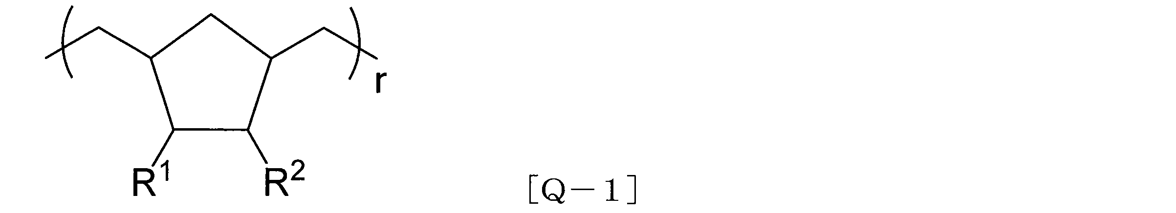

式[Q-2]中、R3は、水素原子;炭素数1~6の直鎖状もしくは分岐状の飽和炭化水素基(アルキル基);塩素もしくはフッ素のハロゲン原子;およびハロゲン原子が塩素原子もしくはフッ素原子であるトリハロメチル基からなる群から選ばれる一価基を表わす。R4、R5は、それぞれ独立に、同一または異なって、水素原子;炭素数1~6の直鎖状もしくは分岐状の飽和の炭化水素基;塩素もしくはフッ素のハロゲン原子;およびハロゲン原子が塩素原子もしくはフッ素原子であるトリハロメチル基からなる群から選ばれる一価基を表わす。また、R4またはR5の炭化水素基は、隣り合う置換部位で互いに結合して5~7員環の飽和炭化水素の環状構造を少なくとも1つ形成してもよい。x、yは0より大きく1より小さい実数であり、x+y=1の関係式を満たす。
無機蛍光体としては、例えば、II族-VI族化合物半導体のナノ結晶、III族-V族化合物半導体のナノ結晶等が挙げられる。これらのナノ結晶の形態は特に限定されず、例えば、InPナノ結晶のコア部分に、ZnS/ZnO等からなるシェル部分が被覆されたコア・シェル(core-shell)構造を有する結晶、またはコア・シェルの境が明確でなくグラジエント(gradient)に組成が変化する構造を有する結晶、あるいは同一の結晶内に2種以上の化合物結晶が部分的に分けられて存在する混合結晶または2種以上のナノ結晶化合物の合金等が挙げられる。
次に、無機蛍光体の表面に配位するキャッピング剤(有機不動態層を形成する為の試剤)としては、炭素数2~30、好ましくは炭素数4~20、より好ましくは炭素数6~18の直鎖構造または分岐構造を有する脂肪族炭化水素基を有する有機分子が挙げられる。無機蛍光体の表面に配位するキャッピング剤(有機不動態層を形成するための試剤)は、無機蛍光体に配位するための官能基を有する。このような官能基としては、例えば、カルボキシル基、アミノ基、アミド基、ニトリル基、水酸基、エーテル基、カルボニル基、スルフォニル基、ホスフォニル基またはメルカプト基等が挙げられる。これらの中でも、カルボキシル基が好ましい。
実施形態1で使用する量子ドット蛍光体は、所望の化合物半導体のナノ結晶が得られる金属前駆体を用いてナノ結晶を製造した後、次いで、これをさらに有機溶媒に分散する。そして、ナノ結晶を所定の反応性化合物(シェル部分の化合物)により処理することにより、無機蛍光体の表面に炭化水素基が配位した構造を有する量子ドット蛍光体を調製することができる。処理方法は、特に制限されず、例えば、ナノ結晶の分散液を反応性化合物の存在下に還流させる方法が挙げられる。また、量子ドット蛍光体の製造方法としては、例えば、特開2006-199963号公報に開示された方法を用いてよい。
図5には、実施形態2にかかる量子ドット蛍光体を含む構造物の一例の断面図が示される。図5において、量子ドット蛍光体を含む構造物は、量子ドット蛍光体18が分散用樹脂中に濃度0.01~20質量%の範囲で分散されている量子ドット蛍光体分散樹脂成形体22と、量子ドット蛍光体分散樹脂成形体22の全面を被覆し、量子ドット蛍光体分散樹脂成形体22への酸素等の透過を低減するガスバリア層(保護シート)24とを含んで構成されている。なお、他の実施形態において、ガスバリア層24は、量子ドット蛍光体分散樹脂成形体22の表面の一部を被覆する構成であってもよい(図6、7参照)。また、前記ガスバリア層24は、酸素の他、水蒸気の透過を低減できるものであることが好ましい。
本発明の電子デバイス(好適には量子ドット蛍光体を含む電子デバイス)に用いる多層構造体は、基材(X)と、基材(X)上に積層された層(Y)とを含む。層(Y)は、金属酸化物(A)とリン化合物(B)とイオン価(FZ)が1以上3以下である陽イオン(Z)とを含有する。リン化合物(B)は、金属酸化物(A)と反応可能な部位を含有する。層(Y)において、金属酸化物(A)を構成する金属原子(M)のモル数(NM)と、リン化合物(B)に由来するリン原子のモル数(NP)とは、0.8≦NM/NP≦4.5の関係を満たす。層(Y)において、金属酸化物(A)を構成する金属原子(M)のモル数(NM)と、陽イオン(Z)のモル数(NZ)と、陽イオン(Z)のイオン価(FZ)とは、0.001≦FZ×NZ/NM≦0.60の関係を満たす。なお、金属原子(M)は、金属酸化物(A)に含まれるすべての金属原子を意味する。
基材(X)の材質は特に制限されず、様々な材質からなる基材を用いることができる。基材(X)の材質としては、例えば、熱可塑性樹脂、熱硬化性樹脂等の樹脂;木材;ガラス;金属;金属酸化物等が挙げられる。これらの中でも、熱可塑性樹脂および繊維集合体が好ましく、熱可塑性樹脂がより好ましい。基材(X)の形態は、特に制限されず、フィルムまたはシート等の層状であってもよい。基材(X)としては、熱可塑性樹脂フィルムおよび無機蒸着層からなる群より選ばれる少なくとも1種を含むものが好ましい。この場合の基材は単層であってもよいし、複層であってもよい。基材(X)は、熱可塑性樹脂フィルム層を含むものがより好ましく、熱可塑性樹脂フィルム層に加えて無機蒸着層(X’)をさらに含んでもよい。
無機蒸着層(X’)は、酸素や水蒸気に対するバリア性を有するものであることが好ましく、透明性を有するものであることがより好ましい。無機蒸着層(X’)は、無機物を蒸着することによって形成することができる。無機物としては、例えば、金属(例えば、アルミニウム)、金属酸化物(例えば、酸化ケイ素、酸化アルミニウム)、金属窒化物(例えば、窒化ケイ素)、金属窒化酸化物(例えば、酸窒化ケイ素)、または金属炭化窒化物(例えば、炭窒化ケイ素)等が挙げられる。これらの中でも、酸化アルミニウム、酸化ケイ素、酸化マグネシウム、または窒化ケイ素で形成される無機蒸着層は、酸素や水蒸気に対するバリア性が優れる観点から好ましい。
金属酸化物(A)を構成する金属原子(M)は、原子価が2価以上であることが好ましい。金属原子(M)としては、例えば、マグネシウム、カルシウム等の周期表第2族の金属原子;チタン、ジルコニウム等の周期表第4族の金属原子;亜鉛等の周期表第12族の金属原子;ホウ素、アルミニウム等の周期表第13族の金属原子;ケイ素等の周期表第14族の金属原子等を挙げることができる。なお、ホウ素およびケイ素は半金属原子に分類される場合があるが、本明細書ではこれらを金属原子に含めるものとする。金属原子(M)は1種類であってもよいし、2種類以上であってもよい。これらの中でも、金属酸化物(A)の生産性や得られる多層構造体のガスバリア性や水蒸気バリア性がより優れることから、金属原子(M)は、アルミニウム、チタン、およびジルコニウムからなる群より選ばれる少なくとも1種であることが好ましく、アルミニウムであることがより好ましい。すなわち、金属原子(M)はアルミニウムを含むことが好ましい。
リン化合物(B)との反応の制御が容易になり、得られる多層構造体のガスバリア性が優れることから、化合物(L)は、下記一般式[I]で示される化合物(L1)を少なくとも1種含むことが好ましい。
M1(R1)m(R2)n―m [I]
式中、M1は、アルミニウム、チタン、およびジルコニウムからなる群より選ばれる。R1は、ハロゲン原子(フッ素原子、塩素原子、臭素原子、ヨウ素原子)、NO3、置換基を有していてもよい炭素数1~9のアルコキシ基、置換基を有していてもよい炭素数1~9のアシロキシ基、置換基を有していてもよい炭素数3~9のアルケニルオキシ基、置換基を有していてもよい炭素数5~15のβ-ジケトナト基、または置換基を有していてもよい炭素数1~9のアシル基を有するジアシルメチル基である。R2は、置換基を有していてもよい炭素数1~9のアルキル基、置換基を有していてもよい炭素数7~10のアラルキル基、置換基を有していてもよい炭素数2~9のアルケニル基、または置換基を有していてもよい炭素数6~10のアリール基である。mは1~nの整数である。nはM1の原子価に等しい。R1が複数存在する場合、R1は互いに同一であってもよいし異なっていてもよい。R2が複数存在する場合、R2は互いに同一であってもよいし異なっていてもよい。
リン化合物(B)は、金属酸化物(A)と反応可能な部位を含有し、典型的には、そのような部位を複数含有する。リン化合物(B)としては、無機リン化合物が好ましい。リン化合物(B)としては、金属酸化物(A)と反応可能な部位(原子団または官能基)を2~20個含有する化合物が好ましい。そのような部位には、金属酸化物(A)の表面に存在する官能基(例えば、水酸基)と縮合反応可能な部位が含まれる。そのような部位としては、例えば、リン原子に直接結合したハロゲン原子、リン原子に直接結合した酸素原子等が挙げられる。金属酸化物(A)の表面に存在する官能基(例えば、水酸基)は、通常、金属酸化物(A)を構成する金属原子(M)に結合している。
本発明の多層構造体は、層(Y)において、NMとNPとが、0.8≦NM/NP≦4.5の関係を満たすものであり、1.0≦NM/NP≦3.6の関係を満たすものが好ましく、1.1≦NM/NP≦3.0の関係を満たすものがより好ましい。NM/NPの値が4.5を超えると、金属酸化物(A)がリン化合物(B)に対して過剰となり、金属酸化物(A)とリン化合物(B)との結合が不充分となり、また、金属酸化物(A)の表面に存在する水酸基の量が多くなるため、ガスバリア性とその安定性が低下する傾向がある。一方、NM/NPの値が0.8未満であると、リン化合物(B)が金属酸化物(A)に対して過剰となり、金属酸化物(A)との結合に関与しない余剰なリン化合物(B)が多くなり、また、リン化合物(B)由来の水酸基の量が多くなりやすく、やはりバリア性とその安定性が低下する傾向がある。
反応生成物(D)は、金属酸化物(A)とリン化合物(B)との反応で得られる。ここで、金属酸化物(A)とリン化合物(B)とさらに他の化合物とが反応することで生成する化合物も反応生成物(D)に含まれる。反応生成物(D)は、反応に関与していない金属酸化物(A)および/またはリン化合物(B)を部分的に含んでいてもよい。
陽イオン(Z)のイオン価(FZ)は、1以上3以下である。陽イオン(Z)は周期表第2~7周期の元素を含む陽イオンである。陽イオン(Z)としては、例えば、リチウムイオン、ナトリウムイオン、カリウムイオン、マグネシウムイオン、カルシウムイオン、チタンイオン、ジルコニウムイオン、ランタノイドイオン(例えば、ランタンイオン)、バナジウムイオン、マンガンイオン、鉄イオン、コバルトイオン、ニッケルイオン、銅イオン、亜鉛イオン、ホウ素イオン、アルミニウムイオン、およびアンモニウムイオン等が挙げられ、中でも、リチウムイオン、ナトリウムイオン、カリウムイオン、マグネシウムイオン、カルシウムイオン、亜鉛イオンが好ましい。陽イオン(Z)は1種類であってもよいし、2種類以上を含んでいてもよい。陽イオン(Z)の働きについては、現在のところ明確ではない。1つの仮説では、陽イオン(Z)は、金属酸化物(A)やリン化合物(B)の水酸基との相互作用によって、無機化合物粒子の肥大化を抑制し、より小さな粒子の充填によってバリア層の緻密性が向上する結果、量子ドット蛍光体を含む電子デバイスの性能低下を抑制していると考えられる。そのため、より高い性能低下抑制機能が必要となる場合は、イオン結合を形成できるイオン価(FZ)が小さい陽イオンを用いることが好ましい。
本発明の多層構造体は、層(Y)において、FZとNZとNMとが、0.001≦FZ×NZ/NM≦0.60の関係を満たすものであり、0.001≦FZ×NZ/NM≦0.30の関係を満たすものが好ましく、0.01≦FZ×NZ/NM≦0.30の関係を満たすものがより好ましい。
本発明の多層構造体は、層(Y)において、FZとNZとNPが、0.0008≦FZ×NZ/NP≦1.35の関係を満たすものが好ましく、0.001≦FZ×NZ/NP≦1.00の関係を満たすものがより好ましく、0.0012≦FZ×NZ/NP≦0.35の関係を満たすものがさらに好ましく、0.012≦FZ×NZ/NP≦0.29の関係を満たすものが特に好ましい。
層(Y)は、特定の重合体(C)をさらに含んでもよい。重合体(C)は、例えば、カルボニル基、水酸基、カルボキシル基、カルボン酸無水物基、およびカルボキシル基の塩からなる群より選ばれる少なくとも1種の官能基を含有する重合体である。
多層構造体中の層(Y)は、金属酸化物(A)、化合物(L)、リン化合物(B)、反応生成物(D)、陽イオン(Z)またはその化合物(E)、酸(加水分解縮合に使用する酸触媒、解膠時の酸等)、および重合体(C)に加え、他の成分を含んでいてもよい。他の成分としては、例えば、陽イオン(Z)を含まない炭酸塩、塩酸塩、硝酸塩、炭酸水素塩、硫酸塩、硫酸水素塩、ホウ酸塩等の無機酸金属塩;陽イオン(Z)を含まない酢酸塩、ステアリン酸塩、シュウ酸塩、酒石酸塩等の有機酸金属塩;層状粘土化合物;架橋剤;重合体(C)以外の高分子化合物;可塑剤;酸化防止剤;紫外線吸収剤;難燃剤等が挙げられる。多層構造体中の層(Y)における前記の他の成分の含有量は、層(Y)の質量に対して50質量%以下であることが好ましく、20質量%以下であることがより好ましく、10質量%以下であることがさらに好ましく、5質量%以下であることが特に好ましく、0質量%(他の成分を含まない)であってもよい。
層(Y)の厚さ(多層構造体が2層以上の層(Y)を有する場合には各層(Y)の厚さの合計)は、0.05~4.0μmであることが好ましく、0.1~2.0μmであることがより好ましい。層(Y)を薄くすることによって、印刷、ラミネート等の加工時における多層構造体の寸法変化を低く抑えることができる。また、多層構造体の柔軟性が増すため、その力学的特性を基材自体の力学的特性に近づけることもできる。本発明の多層構造体が2層以上の層(Y)を有する場合、ガスバリア性の観点から、層(Y)1層当たりの厚さは0.05μm以上であることが好ましい。層(Y)の厚さは、層(Y)の形成に用いられる後述する第1コーティング液(U)の濃度や、その塗工方法によって制御することができる。
層(Y)の赤外線吸収スペクトルにおいて、800~1,400cm-1の領域における最大吸収波数は1,080~1,130cm-1の範囲にあることが好ましい。金属酸化物(A)とリン化合物(B)とが反応して反応生成物(D)となる過程において、金属酸化物(A)に由来する金属原子(M)とリン化合物(B)に由来するリン原子(P)とが酸素原子(O)を介して結合したM-O-Pで表される結合を形成する。その結果、赤外線吸収スペクトルにおいて該結合由来の特性吸収帯が生じる。本発明者らによる検討の結果、M-O-Pの結合に基づく吸収帯が1,080~1,130cm-1の領域に見られる場合には、得られた多層構造体が優れたガスバリア性を発現することがわかった。特に、該特性吸収帯が、一般に各種の原子と酸素原子との結合に由来する吸収が見られる800~1,400cm-1の領域において最も強い吸収である場合には、得られた多層構造体がさらに優れたガスバリア性を発現することがわかった。
本発明の多層構造体は、層(W)をさらに含んでもよい。層(W)は、リン原子を含有する官能基を有する重合体(G1)を含む。層(W)は、層(Y)に隣接して配置されることが好ましい。すなわち、層(W)および層(Y)は、互いに接触するように配置されることが好ましい。また、層(W)は、層(Y)を挟んで基材(X)と反対側(好ましくは反対側の表面)に配置されることが好ましい。換言すれば、基材(X)と層(W)との間に層(Y)が配置されることが好ましい。好ましい一例では、層(W)が、層(Y)を挟んで基材(X)と反対側(好ましくは反対側の表面)に配置され、かつ、層(Y)に隣接して配置される。層(W)は、水酸基および/またはカルボキシル基を有する重合体(G2)をさらに含んでもよい。重合体(G2)としては、重合体(C)と同じものを使用することができる。重合体(G1)について、以下に説明する。
リン原子を含有する官能基を有する重合体(G1)が有するリン原子を含有する官能基としては、例えば、リン酸基、亜リン酸基、ホスホン酸基、亜ホスホン酸基、ホスフィン酸基、亜ホスフィン酸基、およびこれらの塩、ならびにこれらから誘導される官能基(例えば、(部分)エステル化合物、ハロゲン化物(例えば、塩化物)、脱水物)等を挙げられる。中でも、リン酸基および/またはホスホン酸基が好ましく、ホスホン酸基がより好ましい。
本発明の製造方法によれば、本発明の多層構造体を容易に製造できる。本発明の多層構造体について説明した事項は本発明の製造方法に適用できるため、重複する説明を省略する場合がある。また、本発明の製造方法について説明した事項は、本発明の多層構造体に適用できる。
工程〔I〕では、金属酸化物(A)と、リン化合物(B)と、陽イオン(Z)のイオン性化合物(E)とを混合する。これらを混合するにあたり、溶媒を添加してもよい。第1コーティング液(U)において、イオン性化合物(E)から陽イオン(Z)が生成される。第1コーティング液(U)は、金属酸化物(A)、リン化合物(B)、および陽イオン(Z)の他に、他の化合物を含んでもよい。
工程〔I-a〕:金属酸化物(A)を含む液体を調製する工程、
工程〔I-b〕:リン化合物(B)を含む溶液を調製する工程、
工程〔I-c〕:前記工程〔I-a〕および〔I-b〕で得られた金属酸化物(A)を含む液体とリン化合物(B)を含む溶液とを混合する工程。
工程〔II〕では、基材(X)上に第1コーティング液(U)を塗工することによって、基材(X)上に層(Y)の前駆体層を形成する。第1コーティング液(U)は、基材(X)の少なくとも一方の面の上に直接塗工してもよい。また、第1コーティング液(U)を塗工する前に、基材(X)の表面を公知のアンカーコーティング剤で処理したり、基材(X)の表面に公知の接着剤を塗工したりする等して、基材(X)の表面に接着層(H)を形成しておいてもよい。
工程〔III〕では、工程〔II〕で形成された前駆体層(層(Y)の前駆体層)を140℃以上の温度で熱処理することによって、層(Y)を形成する。この熱処理温度は第1コーティング液(U)の塗工後の乾燥処理温度よりも高いことが好ましい。
本発明の多層構造体において、層(Y)は、基材(X)と直接接触するように積層されていてもよい。また、層(Y)は、他の層を介して基材(X)に積層されていてもよい。例えば、層(Y)は、接着層(H)を介して基材(X)に積層されていてもよい。この構成によれば、基材(X)と層(Y)との接着性を高めることができる場合がある。接着層(H)は、接着性樹脂で形成してもよい。接着性樹脂からなる接着層(H)は、基材(X)の表面を公知のアンカーコーティング剤で処理するか、基材(X)の表面に公知の接着剤を塗工することによって形成できる。接着剤としては、ポリイソシアネート成分とポリオール成分とを混合し反応させる二液反応型ポリウレタン系接着剤が好ましい。また、アンカーコーティング剤や接着剤に、公知のシランカップリング剤等の少量の添加剤を加えることによって、さらに接着性を高めることができる場合がある。シランカップリング剤としては、例えば、イソシアネート基、エポキシ基、アミノ基、ウレイド基、メルカプト基等の反応性基を有するシランカップリング剤が挙げられるが、これらに限定されるものではない。基材(X)と層(Y)とを接着層(H)を介して強く接着することによって、本発明の多層構造体に対して印刷やラミネート等の加工を施す際に、バリア性や外観の悪化をより効果的に抑制することができる。接着層(H)の厚さは0.01~10.0μmが好ましく、0.03~5.0μmがより好ましい。
本発明の多層構造体は、様々な特性、例えば、ヒートシール性を付与したり、バリア性や力学物性を向上させたりするための他の層を含んでもよい。このような本発明の多層構造体は、例えば、基材(X)に直接または接着層(H)を介して層(Y)を積層させた後に、さらに該他の層を直接または接着層(H)を介して接着または形成することによって製造できる。他の層としては、例えば、インク層やポリオレフィン層等が挙げられるが、これらに限定されない。
本発明の多層構造体の構成の具体例を、以下に示す。また、多層構造体は接着層(H)等の接着層を有していてもよいが、以下の具体例において、当該接着層の記載は省略している。
(1)層(Y)/ポリエステル層、
(2)層(Y)/ポリエステル層/層(Y)、
(3)層(Y)/ポリアミド層、
(4)層(Y)/ポリアミド層/層(Y)、
(5)層(Y)/ポリオレフィン層、
(6)層(Y)/ポリオレフィン層/層(Y)、
(7)層(Y)/水酸基含有ポリマー層、
(8)層(Y)/水酸基含有ポリマー層/層(Y)、
(9)層(Y)/無機蒸着層/ポリエステル層、
(10)層(Y)/無機蒸着層/ポリアミド層、
(11)層(Y)/無機蒸着層/ポリオレフィン層、
(12)層(Y)/無機蒸着層/水酸基含有ポリマー層、
(13)層(Y)/ポリエステル層/ポリアミド層/ポリオレフィン層、
(14)層(Y)/ポリエステル層/層(Y)/ポリアミド層/ポリオレフィン層、
(15)ポリエステル層/層(Y)/ポリアミド層/ポリオレフィン層、
(16)層(Y)/ポリアミド層/ポリエステル層/ポリオレフィン層、
(17)層(Y)/ポリアミド層/層(Y)/ポリエステル層/ポリオレフィン層、
(18)ポリアミド層/層(Y)/ポリエステル層/ポリオレフィン層、
(19)層(Y)/ポリオレフィン層/ポリアミド層/ポリオレフィン層、
(20)層(Y)/ポリオレフィン層/層(Y)/ポリアミド層/ポリオレフィン層、
(21)ポリオレフィン層/層(Y)/ポリアミド層/ポリオレフィン層、
(22)層(Y)/ポリオレフィン層/ポリオレフィン層、
(23)層(Y)/ポリオレフィン層/層(Y)/ポリオレフィン層、
(24)ポリオレフィン層/層(Y)/ポリオレフィン層、
(25)層(Y)/ポリエステル層/ポリオレフィン層、
(26)層(Y)/ポリエステル層/層(Y)/ポリオレフィン層、
(27)ポリエステル層/層(Y)/ポリオレフィン層、
(28)層(Y)/ポリアミド層/ポリオレフィン層、
(29)層(Y)/ポリアミド層/層(Y)/ポリオレフィン層、
(30)ポリアミド層/層(Y)/ポリオレフィン層、
(31)無機蒸着層/層(Y)/ポリエステル層、
(32)無機蒸着層/層(Y)/ポリエステル層/層(Y)/無機蒸着層、
(33)無機蒸着層/層(Y)/ポリアミド層、
(34)無機蒸着層/層(Y)/ポリアミド層/層(Y)/無機蒸着層、
(35)無機蒸着層/層(Y)/ポリオレフィン層、
(36)無機蒸着層/層(Y)/ポリオレフィン層/層(Y)/無機蒸着層
フーリエ変換赤外分光光度計を用い、減衰全反射法で測定した。測定条件は以下の通りとした。
装置:パーキンエルマー株式会社製Spectrum One
測定モード:減衰全反射法
測定領域:800~1,400cm-1
多層構造体を収束イオンビーム(FIB)を用いて切削し、断面観察用の切片(厚さ0.3μm)を作製した。作製した切片を試料台座にカーボンテープで固定し、加速電圧30kVで30秒間白金イオンスパッタを行った。多層構造体の断面を電界放出形透過型電子顕微鏡を用いて観察し、各層の厚さを算出した。測定条件は以下の通りとした。
装置:日本電子株式会社製JEM-2100F
加速電圧:200kV
倍率:250,000倍
多層構造体1.0gに分析等級の高純度硝酸5mLを加えてマイクロ波分解処理を行い、得られた溶液を超純水で50mLに定容することによって、アルミニウムイオン以外の金属イオンの定量分析用溶液を得た。また、この溶液0.5mLを超純水で50mLに定容することによって、アルミニウムイオンの定量分析用溶液を得た。前記の方法で得られた溶液中に含まれる金属イオン量を誘導結合プラズマ発光分光分析装置を用いて内部標準法で定量した。各金属イオンの検出下限は0.1ppmであった。測定条件は以下の通りとした。
装置:パーキンエルマー株式会社製Optima4300DV
RFパワー:1,300W
ポンプ流量:1.50mL/分
補助ガス流量(アルゴン):0.20L/分
キャリアガス流量(アルゴン):0.70L/分
クーラントガス:15.0L/分
多層構造体を1cm×1cmのサイズに裁断し、凍結粉砕した。得られた粉体を、呼び寸法1mmのふるい(標準ふるい規格JIS-Z8801-1~3準拠)でふるい分けした。前記のふるいを通過した粉体10gをイオン交換水50mL中に分散させ、95℃で10時間抽出操作を行った。得られた抽出液中に含まれるアンモニウムイオンを陽イオンクロマトグラフィー装置を用いて定量した。検出下限は0.02ppbであった。測定条件は以下の通りとした。
装置:Dionex社製ICS-1600
ガードカラム:Dionex社製IonPAC CG-16(5φ×50mm)
分離カラム:Dionex社製IonPAC CS-16(5φ×250mm)
検出器:電気伝導度検出器
溶離液:30ミリモル/L メタンスルホン酸水溶液
温度:40℃
溶離液流速:1mL/分
分析量:25μL
酸素透過量測定装置にキャリアガス側に基材の層が向くようにサンプルを取り付け、等圧法により酸素透過度を測定した。測定条件は以下の通りとした。
装置:モダンコントロール社製MOCON OX-TRAN2/20
温度:20℃
酸素供給側の湿度:85%RH
キャリアガス側の湿度:85%RH
酸素圧:1気圧
キャリアガス圧力:1気圧
水蒸気透過量測定装置にキャリアガス側に基材の層が向くようにサンプルを取り付け、等圧法により透湿度(水蒸気透過度)を測定した。測定条件は以下の通りとした。
装置:モダンコントロール社製MOCON PERMATRAN W3/33
温度:40℃
水蒸気供給側の湿度:90%RH
キャリアガス側の湿度:0%RH
水蒸気透過量測定装置に水蒸気供給側に基材の層が向くようにサンプルを取り付け、差圧法により透湿度(水蒸気透過度)を測定した。測定条件は以下の通りとした。
装置:Technolox社製Deltaperm
温度:40℃
水蒸気供給(上室)側の圧力:50Torr(6,665Pa)
水蒸気透過(下室)側の圧力:0.003Torr(0.4Pa)
窒素雰囲気下、2-ホスホノオキシエチルメタクリレート8.5gおよびアゾビスイソブチロニトリル0.1gをメチルエチルケトン17gに溶解させ、80℃で12時間攪拌した。得られた重合体溶液を冷却した後、1,2-ジクロロエタン170gに加え、デカンテーションによって重合体を沈殿物として回収した。続いて、重合体をテトラヒドロフランに溶解させ、1,2-ジクロロエタンを貧溶媒として用いて再沈精製を行った。再沈精製を3回行った後、50℃で24時間真空乾燥することによって、重合体(G1-1)を得た。重合体(G1-1)は、2-ホスホノオキシエチルメタクリレートの重合体である。GPC分析の結果、該重合体の数平均分子量はポリスチレン換算で10,000であった。
窒素雰囲気下、ビニルホスホン酸10gおよび2,2’-アゾビス(2-アミジノプロパン)2塩酸塩0.025gを水5gに溶解させ、80℃で3時間攪拌した。冷却後、重合溶液に水15gを加えて希釈し、セルロース膜であるスペクトラムラボラトリーズ社製の「Spectra/Por」(登録商標)を用いてろ過した。ろ液中の水を留去した後、50℃で24時間真空乾燥することによって、重合体(G1-2)を得た。重合体(G1-2)は、ポリ(ビニルホスホン酸)である。GPC分析の結果、該重合体の数平均分子量はポリエチレングリコール換算で10,000であった。
蒸留水230質量部を撹拌しながら70℃に昇温した。その蒸留水に、トリイソプロポキシアルミニウム88質量部を1時間かけて滴下し、液温を徐々に95℃まで上昇させ、発生するイソプロパノールを留出させることによって加水分解縮合を行った。得られた液体に、60質量%の硝酸水溶液4.0質量部を添加し、95℃で3時間撹拌することによって加水分解縮合物の粒子の凝集体を解膠させた。その後、その液体に濃度が1.0モル%の水酸化ナトリウム水溶液2.24質量部を加え、固形分濃度が酸化アルミニウム換算で10質量%になるように濃縮した。こうして得られた液体18.66質量部に対して、蒸留水58.19質量部、メタノール19.00質量部、および5質量%のポリビニルアルコール水溶液(株式会社クラレ製PVA124;ケン化度98.5モル%、粘度平均重合度2,400、20℃での4質量%水溶液粘度60mPa・s)0.50質量部を加え、均一になるように撹拌し、金属酸化物(A)を含む液体である分散液を得た。続いて、液温を15℃に維持した状態で前記分散液を攪拌しながらリン化合物(B)を含む溶液である85質量%のリン酸水溶液3.66質量部を滴下して加え、滴下完了後からさらに30分間攪拌を続け、表1に記載されたNM/NP、FZ×NZ/NM、およびFZ×NZ/NPの値を有する目的の第1コーティング液(U-1)を得た。
第1コーティング液(U-2)~(U-5)の調製では、分散液の調製において、FZ×NZ/NMおよびFZ×NZ/NPの値が後掲の表1に示す値となるように1.0モル%の水酸化ナトリウム水溶液の添加量を変更した。このこと以外は第1コーティング液(U-1)の調製と同様の方法によって、第1コーティング液(U-2)~(U-5)を調製した。
第1コーティング液(U-6)の調製では、分散液の調製において、水酸化ナトリウム水溶液を添加せず、かつ、加える蒸留水の量を58.09質量部(第1コーティング液(U-1)の調製では58.19質量部)とした。また、分散液にリン酸水溶液を滴下した後、1.0モル%の水酸化ナトリウム水溶液0.10質量部を添加した。これらのこと以外は第1コーティング液(U-1)の調製と同様の方法によって、第1コーティング液(U-6)を調製した。
リン化合物(B)を含む溶液において、リン酸の代わりにリン酸トリメチルを用いたこと以外は第1コーティング液(U-5)の調製と同様の方法によって、第1コーティング液(U-8)を調製した。
分散液の調製において、5質量%のポリビニルアルコール水溶液の代わりに5質量%のポリアクリル酸水溶液を用いたこと以外は第1コーティング液(U-5)の調製と同様の方法によって、第1コーティング液(U-9)を調製した。
分散液の調製において、1.0モル%の水酸化ナトリウム水溶液の代わりに各種金属塩の水溶液を使用した以外は第1コーティング液(U-5)の調製と同様の方法によって、第1コーティング液(U-7)および(U-10)~(U-18)を調製した。金属塩の水溶液として、第1コーティング液(U-7)では1.0モル%の塩化ナトリウム水溶液、第1コーティング液(U-10)では1.0モル%の水酸化リチウム水溶液、第1コーティング液(U-11)では1.0モル%の水酸化カリウム水溶液、第1コーティング液(U-12)では0.5モル%の塩化カルシウム水溶液、第1コーティング液(U-13)では0.5モル%の塩化コバルト水溶液、第1コーティング液(U-14)では0.5モル%の塩化亜鉛水溶液、第1コーティング液(U-15)では0.5モル%の塩化マグネシウム水溶液、第1コーティング液(U-16)では1.0モル%のアンモニア水溶液、第1コーティング液(U-17)では塩水溶液(1.0モル%の塩化ナトリウム水溶液と0.5モル%の塩化カルシウム水溶液との混合液)、第1コーティング液(U-18)では塩水溶液(0.5モル%の塩化亜鉛水溶液と0.5モル%の塩化カルシウム水溶液との混合液)を用いた。
NM/NPおよびFZ×NZ/NPの比率を後掲の表1に従って変更したこと以外は第1コーティング液(U-5)の調製と同様の方法によって、第1コーティング液(U-19)~(U-23)を調製した。
分散液の調製において、第1コーティング液(U-34)では0.19質量部の酸化亜鉛、第1コーティング液(U-36)では0.19質量部の酸化マグネシウム、第1コーティング液(U-37)では0.38質量部のホウ酸、第1コーティング液(U-39)では0.30質量部の炭酸カルシウム、第1コーティング液(CU-5)では0.38質量部のテトラエトキシシランを、水酸化ナトリウム水溶液の代わりに用いた。これらはいずれも、ポリビニルアルコール水溶液を添加した後に添加した。また、第1コーティング液(U-1)の調製で添加する蒸留水の量58.19質量部を、第1コーティング液(U-34)および第1コーティング液(U-36)では58.00質量部、第1コーティング液(U-39)では57.89質量部、第1コーティング液(U-37)および第1コーティング液(CU-5)では57.81質量部とした。これらの変更以外は第1コーティング液(U-1)の調製と同様の方法によって、第1コーティング液(U-34)、(U-36)、(U-37)、(U-39)、および(CU-5)を調製した。
分散液の調製において1.0モル%の水酸化ナトリウム水溶液を添加しなかったこと以外は第1コーティング液(U-1)の調製と同様の方法によって、第1コーティング液(CU-1)を調製した。
分散液の調製において、FZ×NZ/NMの値が表1に示す値となるように1.0モル%の水酸化ナトリウム水溶液の添加量を変更したこと以外は第1コーティング液(U-1)の調製と同様の方法によって、第1コーティング液(CU-2)および(CU-6)を調製した。
NM/NPの値を表1に従って変更したこと以外は第1コーティング液(U-5)の調製と同様の方法によって、第1コーティング液(CU-3)および(CU-4)を調製した。
まず、合成例1で得た重合体(G1-1)を水とメタノールの混合溶媒(質量比で水:メタノール=7:3)に溶解させ、固形分濃度が1質量%の第2コーティング液(V-1)を得た。また、合成例1で得た重合体(G1-1)を91質量%、ポリビニルアルコール(株式会社クラレ製PVA124;ケン化度98.5モル%、粘度平均重合度2,400、20℃での4質量%水溶液粘度60mPa・s)を9質量%含む混合物を準備した。この混合物を、水とメタノールの混合溶媒(質量比で水:メタノール=7:3)に溶解させ、固形分濃度が1質量%の第2コーティング液(V-2)を得た。また、合成例1で得た重合体(G1-1)を91質量%、ポリアクリル酸(数平均分子量210,000、重量平均分子量1,290,000)を9質量%含む混合物を準備した。この混合物を、水とメタノールとの混合溶媒(質量比で水:メタノール=7:3)に溶解させ、固形分濃度が1質量%の第2コーティング液(V-3)を得た。さらに、重合体(G1-1)を重合体(G1-2)に変更した以外は第2コーティング液(V-1)~(V-3)の調製と同様の方法によって、第2コーティング液(V-4)~(V-6)を得た。
1)PET12:延伸ポリエチレンレテフタレートフィルム;東レ株式会社製、「ルミラー P60」(商品名)、厚さ12μm
2)PET125:延伸ポリエチレンテレフタレートフィルム;東レ株式会社製、「ルミラー S10」(商品名)、厚さ125μm)
3)PET50:エチレン-酢酸ビニル共重合体との接着性を向上させたポリエチレンテレフタレートフィルム;東洋紡株式会社製、「シャインビーム Q1A15」(商品名)、厚さ50μm
4)ONY:延伸ナイロンフィルム;ユニチカ株式会社製、「エンブレム ONBC」(商品名)、厚さ15μm
5)CPP50:無延伸ポリプロピレンフィルム;三井化学東セロ株式会社製、「RXC-21」(商品名)、厚さ50μm
6)CPP60:無延伸ポリプロピレンフィルム;三井化学東セロ株式会社製、「RXC-21」(商品名)、厚さ60μm
7)CPP70:無延伸ポリプロピレンフィルム;三井化学東セロ株式会社製、「RXC-21」(商品名)、厚さ70μm
8)CPP100:無延伸ポリプロピレンフィルム;三井化学東セロ株式会社製、「RXC-21」(商品名)、厚さ100μm
<実施例1-1>
まず、基材(X)としてPET12を準備した。この基材上に、乾燥後の厚さが0.5μmとなるようにバーコーターを用いて第1コーティング液(U-1)をコートし、塗工後のフィルムを100℃で5分間乾燥することによって基材上に層(Y)の前駆体層を形成した。続いて、180℃で1分間熱処理することによって層(Y)を形成した。このようにして、層(Y)(0.5μm)/PETという構造を有する多層構造体(1-1)を得た。
第1コーティング液(U-1)の代わりに第1コーティング液(U-2)~(U-23)を用いたこと以外は実施例1の多層構造体(1-1)の作製と同様にして、実施例1-2~1-23の多層構造体(1-2)~(1-23)を作製した。実施例1-4の多層構造体(1-4)の金属イオン含有量を分析した結果、{(ナトリウムイオンのイオン価)x(ナトリウムイオンモル数)}/(アルミニウムイオンモル数)=0.240であった。
PET12上に、乾燥後の厚さが0.5μmとなるようにバーコーターを用いて第1コーティング液(U-4)をコートし、塗工後のフィルムを110℃で5分間乾燥することによって基材上に層(Y)の前駆体層を形成した。続いて、得られた積層体に対して、160℃で1分間熱処理することによって層(Y)を形成した。このようにして、層(Y)(0.5μm)/PETという構造を有する多層構造体を得た。この多層構造体の層(Y)上に、乾燥後の厚さが0.3μmになるようにバーコーターによって第2コーティング液(V-1)をコートし、200℃で1分間乾燥することによって層(W)を形成した。このようにして、層(W)(0.3μm)/層(Y)(0.5μm)/PETという構造を有する実施例1-24の多層構造体(1-24)を得た。
第2コーティング液(V-1)の代わりに第2コーティング液(V-2)~(V-6)を用いたこと以外は実施例1-24の多層構造体(1-24)の作製と同様の方法によって、実施例1-25~1-29の多層構造体(1-25)~(1-29)を得た。
PET12上に、厚さ0.03μmの酸化アルミニウムの蒸着層(X’)を真空蒸着法によって形成した。この蒸着層上に、乾燥後の厚さが0.5μmとなるようにバーコーターを用いて第1コーティング液(U-4)をコートし、塗工後のフィルムを110℃で5分間乾燥することによって基材上に層(Y)の前駆体層を形成した。続いて、得られた積層体に対して、180℃で1分間熱処理することによって層(Y)を形成した。このようにして、層(Y)(0.5μm)/蒸着層(X’)(0.03μm)/PETという構造を有する多層構造体(1-30)を得た。
実施例1-4で得られた多層構造体(1-4)の層(Y)上に、厚さ0.03μmの酸化アルミニウムの蒸着層(X’)を真空蒸着法により形成して、蒸着層(X’)(0.03μm)/層(Y)(0.5μm)/PET(12μm)という構造を有する多層構造体(1-31)を得た。
PET12の両面に、厚さ0.03μmの酸化アルミニウムの蒸着層(X’)を真空蒸着法によって形成した。この、両方の蒸着層上に乾燥後の厚さが0.5μmとなるようにバーコーターを用いて第1コーティング液(U-4)をコートし、塗工後のフィルムを110℃で5分間乾燥することによって層(Y)の前駆体層を形成した。続いて、得られた積層体に対して、乾燥機を用いて180℃で1分間熱処理することによって層(Y)を形成した。このようにして、層(Y)(0.5μm)/蒸着層(X’)(0.03μm)/PET/蒸着層(X’)(0.03μm)/層(Y)(0.5μm)という構造を有する多層構造体(1-32)を得た。
PET12の両面に、乾燥後の厚さがそれぞれ0.5μmとなるようにバーコーターを用いて第1コーティング液(U-4)をコートし、塗工後のフィルムを110℃で5分間乾燥することによって基材上に層(Y)の前駆体層を形成した。続いて、得られた積層体に対して、乾燥機を用いて180℃で1分間熱処理することによって層(Y)を形成した。この積層体の2つの層(Y)の上に厚さ0.03μmの酸化アルミニウムの蒸着層(X’)を真空蒸着法によって形成した。このようにして、蒸着層(X’)(0.03μm)/層(Y)(0.5μm)/PET/層(Y)(0.5μm)/蒸着層(X’)(0.03μm)という構造を有する多層構造体(1-33)を得た。
第1コーティング液(U-1)の代わりに第1コーティング液(U-34)を用いたこと以外は実施例1-1の多層構造体(1-1)の作製と同様の方法によって、実施例1-34の多層構造体(1-34)を得た。
第1コーティング液(U-1)の代わりに第1コーティング液(U-34)を用い、第2コーティング液(V-1)の代わりに第2コーティング液(V-4)を使用したこと以外は実施例1-24の多層構造体(1-24)の作製と同様の方法によって、実施例1-35の多層構造体(1-35)を得た。
PET125上に、バーコーターを用いて第1コーティング液(U-36)を乾燥後の厚さが0.3μmとなるように塗工し、110℃で5分間乾燥させた後、180℃で1分間熱処理を行った。このようにして多層構造体(1-36)を得た。
第1コーティング液(U-36)の代わりに第1コーティング液(U-37)、(U-34)、および(U-39)を使用したこと以外は実施例1-36の多層構造体(1-36)の作製と同様にして、実施例1-37~1-39の多層構造体(1-37)~(1-39)を得た。
第1コーティング液(U-1)の代わりに第1コーティング液(CU-1)~(CU-6)を用いたこと以外は実施例1-1の多層構造体(1-1)の作製と同様にして、比較例1-1~1-6の多層構造体(C1-1)~(C1-6)を作製した。比較例1-1の多層構造体(C1-1)の金属イオン含有量を分析した結果、検出下限未満({(ナトリウムイオンのイオン価)x(ナトリウムイオンモル数)}/(アルミニウムイオンモル数)=0.001未満)であった。
第1コーティング液(U-36)の代わりに第1コーティング液(CU-7)を用いたことを以外は実施例1-36の多層構造体(1-36)の作製と同様にして、比較例1-7の多層構造体(CA7)を作製した。
PVA:ポリビニルアルコール(株式会社クラレ製PVA124)
PAA:ポリアクリル酸(東亜合成株式会社製アロン-15H)
PPEM:ポリ(2-ホスホノオキシエチルメタクリレート)
PVPA:ポリ(ビニルホスホン酸)

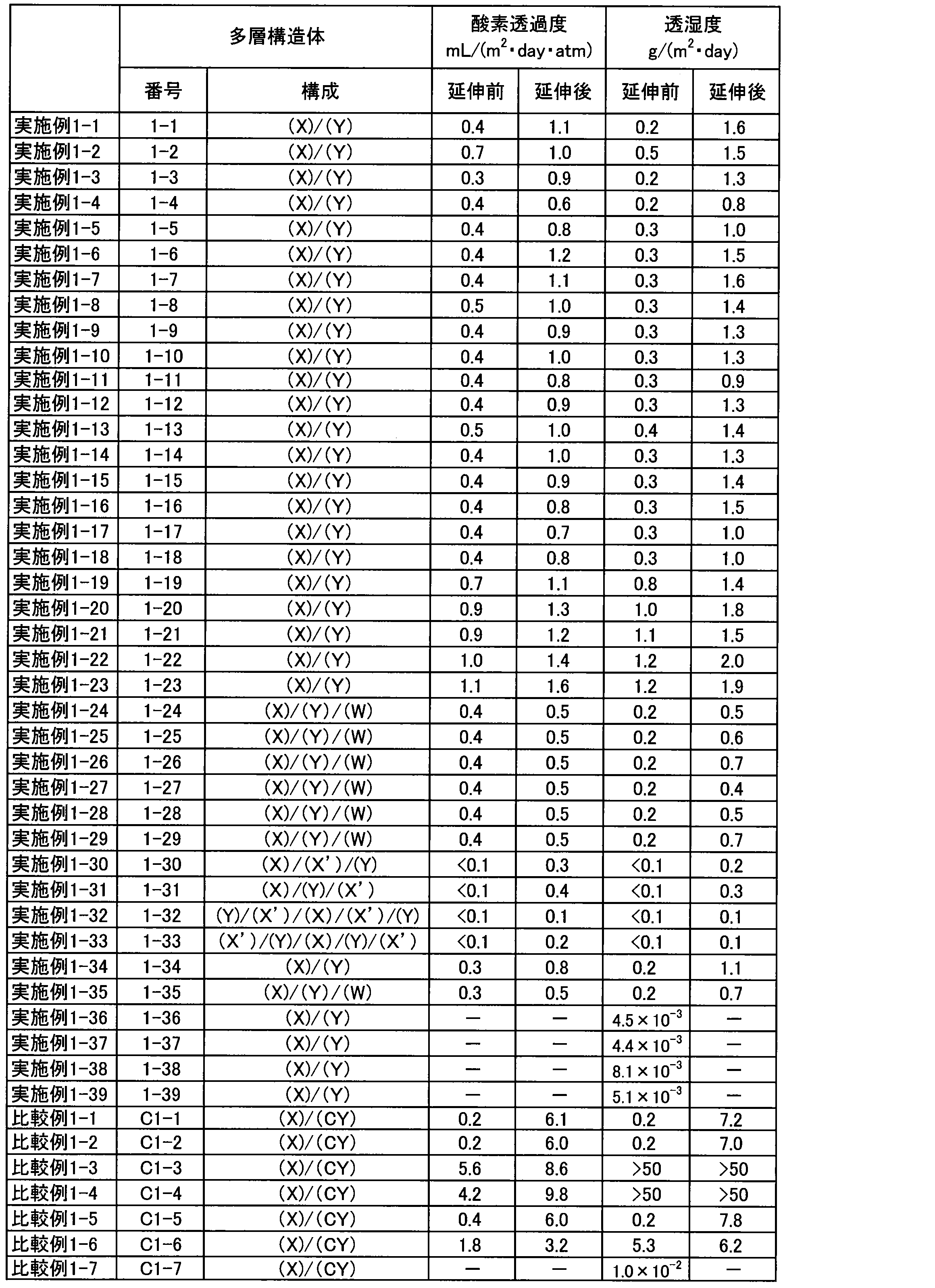
実施例1-1で得た多層構造体(1-1)を保護シートとして用いて太陽電池モジュールを作製した。10cm角の強化ガラス上に設置されたアモルファス系のシリコン太陽電池セルを厚さ450μmの2枚のエチレン-酢酸ビニル共重合体シートで挟み込んだ。次に、光入射側となるエチレン-酢酸ビニル共重合体シート上に多層構造体(1-1)のポリエチレンテレフタレート層が外側となるように貼り合わせた。このようにして太陽電池モジュールを作製した。貼り合わせは、150℃にて真空引きを3分間行った後、9分間圧着を行うことによって実施した。作製された太陽電池モジュールは、大気下で良好に作動し、長期に亘って良好な電気出力特性を示した。
<実施例2-1>
50mLガラス製スクリューボトルに、アルゴンガス雰囲気下、シクロオレフィン重合体(日本ゼオン株式会社製、ZEONEX(登録商標)480R;構造式[Q-1]を含む非晶質樹脂)5gと、真空凍結脱気した後にアルゴンガス雰囲気下で保存した脱水トルエン(和光純薬工業株式会社製)5gとを仕込み、室温下ローラー式攪拌機上で撹拌することで溶解させ、樹脂溶液1を得た。
実施例2-1で得た量子ドット蛍光体分散樹脂成形体1を180℃に加熱したプレス機を用いて、20MPaのプレス圧で加工し、100μmの厚みを持った量子ドット蛍光体を含む樹脂フィルム1を得た。
量子ドット蛍光体を大気から保護するために、前記量子ドット蛍光体分散樹脂成形体2の表面に比較例1-1に記載の多層構造体を用いた以外は、実施例2-1と同様の方法で量子ドット蛍光体を含む構造物3を得た。この量子ドット蛍光体を含む構造物3の量子効率を大塚電子株式会社製量子効率測定装置 QE-1000を用いて測定したところ76%であった。この値は、元になった量子ドット蛍光体トルエン分散液で同様の測定をした場合に得られる量子効率82%と遜色のない結果である。
量子ドット蛍光体を大気から保護するために、前記量子ドット蛍光体分散樹脂成形体2の表面にEVOHフィルム(日本合成化学工業株式会社製、「ソアノール D2908」(商品名)を共押出法により作製した厚さ15μmのフィルム、酸素透過度0.5mL/(m2・day)、透湿度130g/m2・24hrs)を用いた以外は、実施例2-1と同様の方法で量子ドット蛍光体を含む構造物4を得た。この量子ドット蛍光体を含む構造物4の量子効率を大塚電子株式会社製量子効率測定装置 QE-1000を用いて測定したところ76%であった。この値は、元になった量子ドット蛍光体トルエン分散液で同様の測定をした場合に得られる量子効率82%と遜色のない結果である。
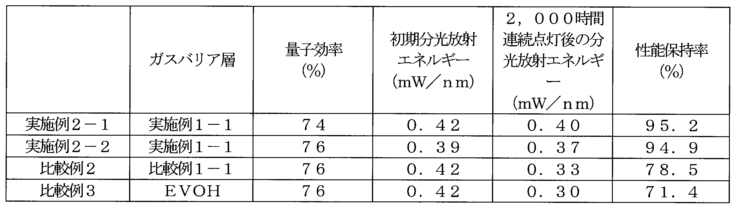
Claims (11)
- 保護シートを含む電子デバイスあって、
前記保護シートが、基材(X)と、前記基材(X)に積層された層(Y)とを含む多層構造体を備え、
前記層(Y)は、金属酸化物(A)とリン化合物(B)とイオン価(FZ)が1以上3以下である陽イオン(Z)とを含有し、
前記リン化合物(B)が、前記金属酸化物(A)と反応可能な部位を含有する化合物であり、
前記層(Y)において、前記金属酸化物(A)を構成する金属原子(M)のモル数(NM)と、前記リン化合物(B)に由来するリン原子のモル数(NP)とが、0.8≦NM/NP≦4.5の関係を満たし、かつ
前記層(Y)において、前記モル数(NM)と、前記陽イオン(Z)のモル数(NZ)と、前記イオン価(FZ)とが、0.001≦FZ×NZ/NM≦0.60の関係を満たすことを特徴とする、電子デバイス。 - 前記陽イオン(Z)が、リチウムイオン、ナトリウムイオン、カリウムイオン、マグネシウムイオン、カルシウムイオン、チタンイオン、ジルコニウムイオン、ランタノイドイオン、バナジウムイオン、マンガンイオン、鉄イオン、コバルトイオン、ニッケルイオン、銅イオン、亜鉛イオン、ホウ素イオン、アルミニウムイオン、およびアンモニウムイオンからなる群より選ばれる少なくとも1種の陽イオンである、請求項1に記載の量子ドット蛍光体を含む電子デバイス。
- さらに、量子ドット蛍光体を含む請求項1または2に記載の電子デバイス。
- 量子ドット蛍光体を含む層の片側または両側に前記保護シートが配置された請求項3に記載の電子デバイス。
- 前記層(Y)において、前記モル数(NM)と、前記モル数(NZ)と、前記イオン価(FZ)とが、0.01≦FZ×NZ/NM≦0.60の関係を満たす、請求項1~4のいずれか1項に記載の電子デバイス。
- 前記リン化合物(B)が、リン酸、ポリリン酸、亜リン酸、ホスホン酸、亜ホスホン酸、ホスフィン酸、亜ホスフィン酸、およびそれらの誘導体からなる群より選ばれる少なくとも1種の化合物である、請求項1~5のいずれか1項に記載の電子デバイス。
- 前記層(Y)の赤外線吸収スペクトルにおいて、800~1,400cm-1の範囲における最大吸収波数が1,080~1,130cm-1の範囲にある、請求項1~6のいずれか1項に記載の電子デバイス。
- 前記基材(X)が熱可塑性樹脂フィルムを含む、請求項1~7のいずれか1項に記載の電子デバイス。
- 前記層(Y)が、カルボニル基、水酸基、カルボキシル基、カルボン酸無水物基、およびカルボキシル基の塩からなる群より選ばれる少なくとも1種の官能基を含有する重合体(C)を含む、請求項1~8のいずれか1項に記載の電子デバイス。
- 前記多層構造体は、前記層(Y)に隣接して配置された層(W)をさらに含み、前記層(W)は、リン原子を含有する官能基を有する重合体(G1)を含む、請求項1~9のいずれか1項に記載の電子デバイス。
- 金属酸化物(A)と、前記金属酸化物(A)と反応可能な部位を含有するリン化合物(B)と、イオン価(FZ)が1以上3以下である陽イオン(Z)のイオン性化合物(E)とを混合することによって第1コーティング液(U)を調製する工程〔I〕と、
前記基材(X)上に前記第1コーティング液(U)を塗工することによって、前記基材(X)上に前記層(Y)の前駆体層を形成する工程〔II〕と、
前記前駆体層を110℃以上の温度で熱処理する工程〔III〕とを含み、
前記第1コーティング液(U)において、前記金属酸化物(A)を構成する金属原子(M)のモル数(NM)と、前記リン化合物(B)に由来するリン原子のモル数(NP)とが、0.8≦NM/NP≦4.5の関係を満たし、かつ
前記第1コーティング液(U)において、前記モル数(NM)と、前記陽イオン(Z)のモル数(NZ)と、前記イオン価(FZ)とが、0.001≦FZ×NZ/NM≦0.60の関係を満たすことを特徴とする、請求項1~10のいずれか1項に記載の電子デバイス。
Priority Applications (5)
| Application Number | Priority Date | Filing Date | Title |
|---|---|---|---|
| KR1020167028839A KR102355119B1 (ko) | 2014-03-18 | 2015-03-18 | 전자 디바이스 |
| JP2015533363A JP5873957B1 (ja) | 2014-03-18 | 2015-03-18 | 電子デバイス |
| EP15764176.2A EP3130458B1 (en) | 2014-03-18 | 2015-03-18 | Electronic device |
| CN201580014281.9A CN106061724B (zh) | 2014-03-18 | 2015-03-18 | 电子设备 |
| US15/126,944 US20170096538A1 (en) | 2014-03-18 | 2015-03-18 | Electronic device |
Applications Claiming Priority (6)
| Application Number | Priority Date | Filing Date | Title |
|---|---|---|---|
| JP2014054968 | 2014-03-18 | ||
| JP2014-054968 | 2014-03-18 | ||
| JP2014164643 | 2014-08-13 | ||
| JP2014164639 | 2014-08-13 | ||
| JP2014-164643 | 2014-08-13 | ||
| JP2014-164639 | 2014-08-13 |
Publications (1)
| Publication Number | Publication Date |
|---|---|
| WO2015141226A1 true WO2015141226A1 (ja) | 2015-09-24 |
Family
ID=54144206
Family Applications (1)
| Application Number | Title | Priority Date | Filing Date |
|---|---|---|---|
| PCT/JP2015/001529 Ceased WO2015141226A1 (ja) | 2014-03-18 | 2015-03-18 | 電子デバイス |
Country Status (7)
| Country | Link |
|---|---|
| US (1) | US20170096538A1 (ja) |
| EP (1) | EP3130458B1 (ja) |
| JP (2) | JP6478735B2 (ja) |
| KR (1) | KR102355119B1 (ja) |
| CN (1) | CN106061724B (ja) |
| TW (1) | TWI650389B (ja) |
| WO (1) | WO2015141226A1 (ja) |
Cited By (16)
| Publication number | Priority date | Publication date | Assignee | Title |
|---|---|---|---|---|
| WO2016076069A1 (ja) * | 2014-11-14 | 2016-05-19 | 富士フイルム株式会社 | 機能性積層フィルム |
| JP2017095575A (ja) * | 2015-11-24 | 2017-06-01 | コニカミノルタ株式会社 | ガスバリアー性粘着シート及びそれを備える電子デバイス |
| JP2017094585A (ja) * | 2015-11-24 | 2017-06-01 | コニカミノルタ株式会社 | ガスバリアーフィルム、ガスバリアーフィルムの製造方法及び電子デバイス |
| WO2017090592A1 (ja) * | 2015-11-24 | 2017-06-01 | コニカミノルタ株式会社 | ガスバリアー性フィルム及びこれを備えた電子デバイス |
| WO2017090602A1 (ja) * | 2015-11-24 | 2017-06-01 | コニカミノルタ株式会社 | ガスバリアー性フィルム及びこれを備えた電子デバイス |
| JP2017120358A (ja) * | 2015-09-30 | 2017-07-06 | 大日本印刷株式会社 | 光波長変換シート、これを備えるバックライト装置、画像表示装置、および光波長変換シートの製造方法 |
| JP2017136737A (ja) * | 2016-02-03 | 2017-08-10 | 凸版印刷株式会社 | 蛍光体用保護フィルム、及びそれを用いた波長変換シート |
| JP2018506625A (ja) * | 2015-12-23 | 2018-03-08 | アファンタマ アクチェンゲゼルシャフト | 発光部品 |
| EP3351378A4 (en) * | 2015-09-17 | 2019-03-06 | Kuraray Co., Ltd. | MULTILAYER STRUCTURE AND METHOD FOR THE MANUFACTURE THEREOF, PACKAGING MATERIAL THEREFOR, PRODUCT AND PROTECTIVE FOIL FOR ELECTRONIC DEVICES |
| WO2019186728A1 (ja) * | 2018-03-27 | 2019-10-03 | 日立化成株式会社 | 波長変換部材、バックライトユニット、及び画像表示装置 |
| WO2021075394A1 (ja) * | 2019-10-15 | 2021-04-22 | Nsマテリアルズ株式会社 | 発光装置 |
| WO2021112252A1 (ja) * | 2019-12-06 | 2021-06-10 | 株式会社クラレ | 多層構造体およびその製造方法、それを用いた包装材および製品、ならびに電子デバイスの保護シート |
| JP2021091101A (ja) * | 2019-12-06 | 2021-06-17 | 株式会社クラレ | 多層構造体およびその製造方法、それを用いた包装材および製品、ならびに電子デバイスの保護シート |
| JP2022502832A (ja) * | 2018-09-27 | 2022-01-11 | ナージン テクノロジー コーポレーション リミテッドNajing Technology Corporation Limited | 発光素子の製造プロセス及び発光素子 |
| JP2022107676A (ja) * | 2016-02-04 | 2022-07-22 | 晶元光電股▲ふん▼有限公司 | 発光素子及びその製造方法 |
| JP7691571B1 (ja) * | 2024-12-20 | 2025-06-11 | artience株式会社 | 封止層形成用シート、および複数の発光素子が封止されている部材 |
Families Citing this family (16)
| Publication number | Priority date | Publication date | Assignee | Title |
|---|---|---|---|---|
| JP6661890B2 (ja) | 2014-05-21 | 2020-03-11 | 日亜化学工業株式会社 | 発光装置 |
| JP6495891B2 (ja) * | 2014-08-06 | 2019-04-03 | Nsマテリアルズ株式会社 | 樹脂成形品及び、波長変換部材、照明部材 |
| JP2016103461A (ja) * | 2014-11-14 | 2016-06-02 | 富士フイルム株式会社 | 波長変換部材及びそれを備えたバックライトユニット、液晶表示装置 |
| US10584282B2 (en) | 2014-12-24 | 2020-03-10 | Kuraray Co., Ltd. | Electronic device and method for producing same |
| KR102353095B1 (ko) | 2014-12-26 | 2022-01-19 | 엔에스 마테리얼스 아이엔씨. | 파장 변환 부재 및 그 제조 방법 |
| WO2017096229A1 (en) * | 2015-12-02 | 2017-06-08 | Nanosys, Inc. | Quantum dot encapsulation techniques |
| WO2017096227A1 (en) | 2015-12-02 | 2017-06-08 | Nanosys, Inc. | Quantum dot based color conversion layer in display devices |
| JP6028177B1 (ja) * | 2015-12-25 | 2016-11-16 | 株式会社野田スクリーン | 光源装置 |
| JP6447557B2 (ja) | 2016-03-24 | 2019-01-09 | 日亜化学工業株式会社 | 発光装置の製造方法 |
| JP2017222071A (ja) * | 2016-06-15 | 2017-12-21 | コニカミノルタ株式会社 | ガスバリアーフィルム、その製造方法及び有機エレクトロルミネッセンスデバイス |
| CN115521774A (zh) * | 2016-12-22 | 2022-12-27 | 住友化学株式会社 | 组合物、膜、层叠结构体、发光装置、显示器及组合物的制造方法 |
| KR102389815B1 (ko) * | 2017-06-05 | 2022-04-22 | 삼성전자주식회사 | 양자점 유리셀 및 이를 포함하는 발광소자 패키지 |
| CN107329319A (zh) * | 2017-07-21 | 2017-11-07 | 苏州星烁纳米科技有限公司 | 量子点膜片及其制备方法、背光模组 |
| TWI654277B (zh) * | 2018-03-23 | 2019-03-21 | 國立清華大學 | 高效率光轉換材料 |
| DE112020005336T5 (de) * | 2019-12-10 | 2022-08-11 | Kuraray Co., Ltd. | Mehrschichtstruktur und verfahren zu deren herstellung, verpackungsmaterial und vakuumisolator, die diese umfassen, sowie schutzfolie für elektronische vorrichtungen |
| JP3250506U (ja) * | 2022-03-31 | 2025-03-11 | シェンツェン ジュフェイ オプトエレクトロニクス カンパニー リミテッド | Ledデバイス |
Citations (3)
| Publication number | Priority date | Publication date | Assignee | Title |
|---|---|---|---|---|
| WO2011122036A1 (ja) * | 2010-03-30 | 2011-10-06 | 株式会社クラレ | 複合構造体、それを用いた包装材料および成形品、複合構造体の製造方法、ならびにコーティング液 |
| WO2013051288A1 (ja) * | 2011-10-05 | 2013-04-11 | 株式会社クラレ | 複合構造体およびその製造方法、それを用いた包装材料および成形品、ならびにコーティング液 |
| WO2013187064A1 (ja) * | 2012-06-14 | 2013-12-19 | 株式会社クラレ | 多層構造体およびそれを用いたデバイス、ならびにそれらの製造方法 |
Family Cites Families (11)
| Publication number | Priority date | Publication date | Assignee | Title |
|---|---|---|---|---|
| BE789159A (fr) * | 1971-09-22 | 1973-03-22 | Du Pont | Articles moules en matieres polymeres recouverts d'une couche d'un phosphate de metal |
| TW309498B (en) * | 1995-06-29 | 1997-07-01 | Sharp Kk | Sealed bag and container for accommodating electronic device, and method for facilitating storing and transporting electronic device using such sealed bag and container |
| JP4106931B2 (ja) | 2002-03-07 | 2008-06-25 | 凸版印刷株式会社 | 透明ガスバリア薄膜被覆フィルム |
| DE10227362A1 (de) | 2002-06-19 | 2004-01-08 | Basf Ag | Komplexbildner für die Behandlung von Metall- und Kunstoffoberflächen |
| JP2005535554A (ja) * | 2002-08-14 | 2005-11-24 | アプライド シン フィルムズ,インコーポレイティッド | リン酸アルミニウム化合物、組成物、材料及び関連複合体 |
| US7318651B2 (en) * | 2003-12-18 | 2008-01-15 | Avago Technologies Ecbu Ip (Singapore) Pte. Ltd. | Flash module with quantum dot light conversion |
| JP2006114909A (ja) | 2004-10-14 | 2006-04-27 | Agilent Technol Inc | フラッシュ・モジュール |
| KR100787463B1 (ko) * | 2007-01-05 | 2007-12-26 | 삼성에스디아이 주식회사 | 글래스 프릿, 실링재 형성용 조성물, 발광 장치 및 발광 장치의 제조방법 |
| KR101702000B1 (ko) * | 2011-10-21 | 2017-02-03 | 삼성전자 주식회사 | 반도체 나노결정-고분자 복합입자, 이의 제조방법 및 이를 포함하는 복합체 필름 및 광전자 소자 |
| JP5801743B2 (ja) * | 2012-03-30 | 2015-10-28 | 株式会社クラレ | 多層構造体およびそれを用いた製品、ならびに多層構造体の製造方法 |
| AU2015233424B2 (en) | 2014-03-18 | 2019-05-16 | Kuraray Co., Ltd. | Multilayer structure and method for producing same, packaging material and product which use same, electronic-device protective sheet, and coating liquid |
-
2015
- 2015-03-18 EP EP15764176.2A patent/EP3130458B1/en active Active
- 2015-03-18 US US15/126,944 patent/US20170096538A1/en not_active Abandoned
- 2015-03-18 CN CN201580014281.9A patent/CN106061724B/zh active Active
- 2015-03-18 WO PCT/JP2015/001529 patent/WO2015141226A1/ja not_active Ceased
- 2015-03-18 KR KR1020167028839A patent/KR102355119B1/ko active Active
- 2015-03-18 JP JP2015055401A patent/JP6478735B2/ja active Active
- 2015-03-18 TW TW104108648A patent/TWI650389B/zh active
- 2015-03-18 JP JP2015533363A patent/JP5873957B1/ja active Active
Patent Citations (3)
| Publication number | Priority date | Publication date | Assignee | Title |
|---|---|---|---|---|
| WO2011122036A1 (ja) * | 2010-03-30 | 2011-10-06 | 株式会社クラレ | 複合構造体、それを用いた包装材料および成形品、複合構造体の製造方法、ならびにコーティング液 |
| WO2013051288A1 (ja) * | 2011-10-05 | 2013-04-11 | 株式会社クラレ | 複合構造体およびその製造方法、それを用いた包装材料および成形品、ならびにコーティング液 |
| WO2013187064A1 (ja) * | 2012-06-14 | 2013-12-19 | 株式会社クラレ | 多層構造体およびそれを用いたデバイス、ならびにそれらの製造方法 |
Non-Patent Citations (1)
| Title |
|---|
| See also references of EP3130458A4 * |
Cited By (28)
| Publication number | Priority date | Publication date | Assignee | Title |
|---|---|---|---|---|
| JP2016093956A (ja) * | 2014-11-14 | 2016-05-26 | 富士フイルム株式会社 | 機能性積層フィルム |
| US10377113B2 (en) | 2014-11-14 | 2019-08-13 | Fujifilm Corporation | Functional laminated film |
| WO2016076069A1 (ja) * | 2014-11-14 | 2016-05-19 | 富士フイルム株式会社 | 機能性積層フィルム |
| US10647487B2 (en) | 2015-09-17 | 2020-05-12 | Kurray Co., Ltd. | Multilayer structure, method for producing same, packaging material and product including same, and protective sheet for electronic device |
| EP3351378A4 (en) * | 2015-09-17 | 2019-03-06 | Kuraray Co., Ltd. | MULTILAYER STRUCTURE AND METHOD FOR THE MANUFACTURE THEREOF, PACKAGING MATERIAL THEREFOR, PRODUCT AND PROTECTIVE FOIL FOR ELECTRONIC DEVICES |
| JP2017120358A (ja) * | 2015-09-30 | 2017-07-06 | 大日本印刷株式会社 | 光波長変換シート、これを備えるバックライト装置、画像表示装置、および光波長変換シートの製造方法 |
| JP2017094585A (ja) * | 2015-11-24 | 2017-06-01 | コニカミノルタ株式会社 | ガスバリアーフィルム、ガスバリアーフィルムの製造方法及び電子デバイス |
| WO2017090602A1 (ja) * | 2015-11-24 | 2017-06-01 | コニカミノルタ株式会社 | ガスバリアー性フィルム及びこれを備えた電子デバイス |
| WO2017090592A1 (ja) * | 2015-11-24 | 2017-06-01 | コニカミノルタ株式会社 | ガスバリアー性フィルム及びこれを備えた電子デバイス |
| JP2017095575A (ja) * | 2015-11-24 | 2017-06-01 | コニカミノルタ株式会社 | ガスバリアー性粘着シート及びそれを備える電子デバイス |
| JP2018506625A (ja) * | 2015-12-23 | 2018-03-08 | アファンタマ アクチェンゲゼルシャフト | 発光部品 |
| KR101917051B1 (ko) | 2015-12-23 | 2018-11-08 | 아반타마 아게 | 발광 성분 |
| US10326058B2 (en) | 2015-12-23 | 2019-06-18 | Avantama Ag | Luminescent component |
| JP2017136737A (ja) * | 2016-02-03 | 2017-08-10 | 凸版印刷株式会社 | 蛍光体用保護フィルム、及びそれを用いた波長変換シート |
| JP7414886B2 (ja) | 2016-02-04 | 2024-01-16 | 晶元光電股▲ふん▼有限公司 | 発光素子及びその製造方法 |
| JP2022107676A (ja) * | 2016-02-04 | 2022-07-22 | 晶元光電股▲ふん▼有限公司 | 発光素子及びその製造方法 |
| WO2019186728A1 (ja) * | 2018-03-27 | 2019-10-03 | 日立化成株式会社 | 波長変換部材、バックライトユニット、及び画像表示装置 |
| JP7218950B2 (ja) | 2018-09-27 | 2023-02-07 | ナージン テクノロジー コーポレーション リミテッド | 発光素子の製造プロセス及び発光素子 |
| US12040426B2 (en) | 2018-09-27 | 2024-07-16 | Najing Technology Corporation Limited | Manufacturing process of light emitting device comprising quantum dot film and transparent adhesive layer |
| JP2022502832A (ja) * | 2018-09-27 | 2022-01-11 | ナージン テクノロジー コーポレーション リミテッドNajing Technology Corporation Limited | 発光素子の製造プロセス及び発光素子 |
| WO2021075394A1 (ja) * | 2019-10-15 | 2021-04-22 | Nsマテリアルズ株式会社 | 発光装置 |
| US12097688B2 (en) | 2019-12-06 | 2024-09-24 | Kuraray Co., Ltd. | Multilayer structure, method for producing same, packaging material and product including same, and protective sheet for electronic device |
| JP7339870B2 (ja) | 2019-12-06 | 2023-09-06 | 株式会社クラレ | 多層構造体およびその製造方法、それを用いた包装材および製品、ならびに電子デバイスの保護シート |
| JP2021091101A (ja) * | 2019-12-06 | 2021-06-17 | 株式会社クラレ | 多層構造体およびその製造方法、それを用いた包装材および製品、ならびに電子デバイスの保護シート |
| JP7458415B2 (ja) | 2019-12-06 | 2024-03-29 | 株式会社クラレ | 多層構造体およびその製造方法、それを用いた包装材および製品、ならびに電子デバイスの保護シート |
| JPWO2021112252A1 (ja) * | 2019-12-06 | 2021-06-10 | ||
| WO2021112252A1 (ja) * | 2019-12-06 | 2021-06-10 | 株式会社クラレ | 多層構造体およびその製造方法、それを用いた包装材および製品、ならびに電子デバイスの保護シート |
| JP7691571B1 (ja) * | 2024-12-20 | 2025-06-11 | artience株式会社 | 封止層形成用シート、および複数の発光素子が封止されている部材 |
Also Published As
| Publication number | Publication date |
|---|---|
| CN106061724B (zh) | 2017-12-26 |
| EP3130458A1 (en) | 2017-02-15 |
| EP3130458B1 (en) | 2019-07-17 |
| TWI650389B (zh) | 2019-02-11 |
| JP5873957B1 (ja) | 2016-03-01 |
| KR20160133553A (ko) | 2016-11-22 |
| KR102355119B1 (ko) | 2022-01-26 |
| CN106061724A (zh) | 2016-10-26 |
| US20170096538A1 (en) | 2017-04-06 |
| JP6478735B2 (ja) | 2019-03-06 |
| TW201540792A (zh) | 2015-11-01 |
| JPWO2015141226A1 (ja) | 2017-04-06 |
| JP2016040119A (ja) | 2016-03-24 |
| EP3130458A4 (en) | 2017-10-11 |
Similar Documents
| Publication | Publication Date | Title |
|---|---|---|
| JP5873957B1 (ja) | 電子デバイス | |
| JP6014791B1 (ja) | 電子デバイスおよびその製造方法 | |
| TWI650233B (zh) | 多層構造物及其製造方法、使用此之包裝材料及製品、電子裝置之保護片以及塗覆液 | |
| CN106575492B (zh) | 多层标签以及使用其的容器和容器的制造方法 | |
| CN107148341B (zh) | 多层结构体及其制造方法、使用其而得的包装材料和制品、以及电子设备的保护片 | |
| TWI687313B (zh) | 多層結構體及使用其之包裝材料 | |
| CN106660323A (zh) | 多层结构体及其制造方法、使用了其的包装材料和制品、以及电子设备 | |
| CN107592836B (zh) | 防静电片以及包含其的包装材料和电子设备 | |
| TWI690426B (zh) | 多層結構體、使用其之包裝材料及製品, 與電子裝置之保護薄片 |
Legal Events
| Date | Code | Title | Description |
|---|---|---|---|
| ENP | Entry into the national phase |
Ref document number: 2015533363 Country of ref document: JP Kind code of ref document: A |
|
| 121 | Ep: the epo has been informed by wipo that ep was designated in this application |
Ref document number: 15764176 Country of ref document: EP Kind code of ref document: A1 |
|
| WWE | Wipo information: entry into national phase |
Ref document number: 15126944 Country of ref document: US |
|
| NENP | Non-entry into the national phase |
Ref country code: DE |
|
| REEP | Request for entry into the european phase |
Ref document number: 2015764176 Country of ref document: EP |
|
| WWE | Wipo information: entry into national phase |
Ref document number: 2015764176 Country of ref document: EP |
|
| ENP | Entry into the national phase |
Ref document number: 20167028839 Country of ref document: KR Kind code of ref document: A |