WO2015141274A1 - Dispositif d'évacuation de fluide et procédé de commande associé - Google Patents
Dispositif d'évacuation de fluide et procédé de commande associé Download PDFInfo
- Publication number
- WO2015141274A1 WO2015141274A1 PCT/JP2015/051791 JP2015051791W WO2015141274A1 WO 2015141274 A1 WO2015141274 A1 WO 2015141274A1 JP 2015051791 W JP2015051791 W JP 2015051791W WO 2015141274 A1 WO2015141274 A1 WO 2015141274A1
- Authority
- WO
- WIPO (PCT)
- Prior art keywords
- liquid
- ink
- discharge
- path
- flow path
- Prior art date
- Legal status (The legal status is an assumption and is not a legal conclusion. Google has not performed a legal analysis and makes no representation as to the accuracy of the status listed.)
- Ceased
Links
Images



Classifications
-
- B—PERFORMING OPERATIONS; TRANSPORTING
- B41—PRINTING; LINING MACHINES; TYPEWRITERS; STAMPS
- B41J—TYPEWRITERS; SELECTIVE PRINTING MECHANISMS, i.e. MECHANISMS PRINTING OTHERWISE THAN FROM A FORME; CORRECTION OF TYPOGRAPHICAL ERRORS
- B41J2/00—Typewriters or selective printing mechanisms characterised by the printing or marking process for which they are designed
- B41J2/005—Typewriters or selective printing mechanisms characterised by the printing or marking process for which they are designed characterised by bringing liquid or particles selectively into contact with a printing material
- B41J2/01—Ink jet
- B41J2/135—Nozzles
- B41J2/165—Prevention or detection of nozzle clogging, e.g. cleaning, capping or moistening for nozzles
- B41J2/16585—Prevention or detection of nozzle clogging, e.g. cleaning, capping or moistening for nozzles for paper-width or non-reciprocating print heads
-
- B—PERFORMING OPERATIONS; TRANSPORTING
- B41—PRINTING; LINING MACHINES; TYPEWRITERS; STAMPS
- B41J—TYPEWRITERS; SELECTIVE PRINTING MECHANISMS, i.e. MECHANISMS PRINTING OTHERWISE THAN FROM A FORME; CORRECTION OF TYPOGRAPHICAL ERRORS
- B41J2/00—Typewriters or selective printing mechanisms characterised by the printing or marking process for which they are designed
- B41J2/005—Typewriters or selective printing mechanisms characterised by the printing or marking process for which they are designed characterised by bringing liquid or particles selectively into contact with a printing material
- B41J2/01—Ink jet
- B41J2/135—Nozzles
- B41J2/165—Prevention or detection of nozzle clogging, e.g. cleaning, capping or moistening for nozzles
- B41J2/16505—Caps, spittoons or covers for cleaning or preventing drying out
- B41J2/16508—Caps, spittoons or covers for cleaning or preventing drying out connected with the printer frame
-
- B—PERFORMING OPERATIONS; TRANSPORTING
- B41—PRINTING; LINING MACHINES; TYPEWRITERS; STAMPS
- B41J—TYPEWRITERS; SELECTIVE PRINTING MECHANISMS, i.e. MECHANISMS PRINTING OTHERWISE THAN FROM A FORME; CORRECTION OF TYPOGRAPHICAL ERRORS
- B41J2/00—Typewriters or selective printing mechanisms characterised by the printing or marking process for which they are designed
- B41J2/005—Typewriters or selective printing mechanisms characterised by the printing or marking process for which they are designed characterised by bringing liquid or particles selectively into contact with a printing material
- B41J2/01—Ink jet
- B41J2/135—Nozzles
- B41J2/165—Prevention or detection of nozzle clogging, e.g. cleaning, capping or moistening for nozzles
- B41J2/16517—Cleaning of print head nozzles
- B41J2/1652—Cleaning of print head nozzles by driving a fluid through the nozzles to the outside thereof, e.g. by applying pressure to the inside or vacuum at the outside of the print head
- B41J2/16526—Cleaning of print head nozzles by driving a fluid through the nozzles to the outside thereof, e.g. by applying pressure to the inside or vacuum at the outside of the print head by applying pressure only
-
- B—PERFORMING OPERATIONS; TRANSPORTING
- B41—PRINTING; LINING MACHINES; TYPEWRITERS; STAMPS
- B41J—TYPEWRITERS; SELECTIVE PRINTING MECHANISMS, i.e. MECHANISMS PRINTING OTHERWISE THAN FROM A FORME; CORRECTION OF TYPOGRAPHICAL ERRORS
- B41J2/00—Typewriters or selective printing mechanisms characterised by the printing or marking process for which they are designed
- B41J2/005—Typewriters or selective printing mechanisms characterised by the printing or marking process for which they are designed characterised by bringing liquid or particles selectively into contact with a printing material
- B41J2/01—Ink jet
- B41J2/17—Ink jet characterised by ink handling
- B41J2/175—Ink supply systems ; Circuit parts therefor
-
- B—PERFORMING OPERATIONS; TRANSPORTING
- B41—PRINTING; LINING MACHINES; TYPEWRITERS; STAMPS
- B41J—TYPEWRITERS; SELECTIVE PRINTING MECHANISMS, i.e. MECHANISMS PRINTING OTHERWISE THAN FROM A FORME; CORRECTION OF TYPOGRAPHICAL ERRORS
- B41J2/00—Typewriters or selective printing mechanisms characterised by the printing or marking process for which they are designed
- B41J2/005—Typewriters or selective printing mechanisms characterised by the printing or marking process for which they are designed characterised by bringing liquid or particles selectively into contact with a printing material
- B41J2/01—Ink jet
- B41J2/135—Nozzles
- B41J2/165—Prevention or detection of nozzle clogging, e.g. cleaning, capping or moistening for nozzles
- B41J2/16585—Prevention or detection of nozzle clogging, e.g. cleaning, capping or moistening for nozzles for paper-width or non-reciprocating print heads
- B41J2002/16591—Prevention or detection of nozzle clogging, e.g. cleaning, capping or moistening for nozzles for paper-width or non-reciprocating print heads for line print heads above an endless belt
Definitions
- the present invention relates to a liquid ejection device and a control method thereof.
- the discharge head includes a plurality of pressure chambers and nozzles provided in the respective pressure chambers. And the piezoelectric element provided in each pressure chamber deform
- purge is performed in order to eliminate sedimentation in the discharge head.
- purging methods such as a pressure purge that pressurizes the inside of the ejection head and ejects the liquid from the nozzle, and a suction purge that sucks the liquid in the ejection head from the nozzle by an external device connected to the nozzle. ing.
- the ink flow rate and flow velocity in the ejection head are very large as compared with the normal ink ejection, the ink flows in the same direction as the normal ink ejection. Therefore, in the liquid flow path of the discharge head, in the region where the ink flow is unlikely to occur during normal ink discharge, that is, in the region where the sedimentation component is likely to stay, the ink flow is difficult to occur even in the purge operation. It is difficult to eliminate the retention of components.
- the present invention has been made in view of such circumstances, and an object of the present invention is to provide a technique capable of efficiently eliminating the retention of sedimentary components in the liquid flow path of the discharge head.
- a first invention of the present application provides a discharge head having a plurality of nozzles for discharging a liquid, a liquid storage section for storing the liquid, and pressurizing the inside of the liquid storage section.
- An open / close unit that can be switched between an open state that ensures communication and a closed state that blocks communication of the discharge path, and a control unit that controls the pressurization unit and the open / close unit, and the discharge
- the head has a liquid flow path having a supply port communicating with the supply path, a discharge port communicating with the discharge path, a liquid filling chamber having a communication port communicating with the liquid flow path, and one end of the liquid filling chamber. The other end communicates with the liquid filling chamber and the other end of the discharge head.
- a plurality of the nozzles that are exposed, and the control unit causes the pressurization unit to perform pressurization while the open / close unit is in the open state, and the liquid storage unit is configured to perform the pressurization.
- the liquid stored in the liquid channel is supplied to the liquid flow channel via the supply channel, and at least a part of the liquid supplied to the liquid flow channel is discharged to the discharge channel via the discharge port.
- a second invention of the present application is the liquid ejection apparatus according to the first invention, wherein the liquid filling chamber has the communication port directly communicating with the liquid flow path, and the first liquid filling chamber. And a plurality of second liquid filling chambers that communicate directly or indirectly with each of the single nozzles.
- a third invention of the present application is the liquid ejection apparatus according to the second invention, wherein each of the second liquid filling chambers is provided with a pressure generating element, and when the pressure generating element is driven, the second liquid filling chamber is provided. Is pressurized, and the liquid is ejected as droplets from the nozzle.
- a fourth invention of the present application is the liquid ejecting apparatus according to any one of the first to third inventions, wherein the liquid stored in the liquid storage unit, when the pressurization is performed, passes through the supply path. A part of the liquid supplied to the liquid flow path and discharged to the liquid flow path is discharged to the discharge path through the discharge port, and another part of the liquid supplied to the liquid flow path. The part is discharged from the plurality of nozzles through the liquid filling chamber.
- a fifth invention of the present application is the liquid ejection device according to the fourth invention, wherein when the pressurization is performed, the flow rate of the liquid discharged from the liquid channel to the discharge channel through the discharge port is plural. Greater than the total flow rate of the liquid discharged from the nozzle.
- a discharge head having a plurality of nozzles for discharging a liquid, a liquid storage section for storing the liquid supplied to the discharge head via a supply path, and discharging the liquid from the discharge head.
- a control method of a liquid ejection device comprising a discharge path and a pressurizing unit that pressurizes the inside of the liquid storage part, wherein the open / close part provided in the discharge path is opened to ensure communication of the discharge path In this state, pressurization is performed by the pressurization unit, and when the pressurization is performed, the liquid stored in the liquid storage unit is supplied to the liquid flow path in the discharge head via the supply path.
- a method for controlling a liquid ejection apparatus wherein at least a part of the liquid supplied to the liquid flow path is discharged to the discharge path.
- the 7th invention of this application is the control method of the liquid discharge apparatus of 6th invention, Comprising:
- the said discharge head has the supply port connected to the said supply path, and the discharge port connected to the said discharge path,
- the said liquid A liquid filling chamber having a flow path, a communication port communicating with the liquid flow path, and a plurality of the nozzles having one end communicating with the liquid filling chamber and the other end exposed to the outside of the discharge head.
- a part of the liquid supplied to the liquid flow path is discharged to the discharge path through the discharge port and the liquid supplied to the liquid flow path is Another part is discharged from the plurality of nozzles through the liquid filling chamber.
- An eighth invention of the present application is the method for controlling a liquid ejection apparatus according to the seventh invention, wherein the flow rate of the liquid discharged from the liquid flow path to the discharge path through the discharge port when the pressurization is performed. Is larger than the total flow rate of the liquid ejected from the plurality of nozzles.
- the liquid flow toward the discharge path is generated in the liquid flow path by performing the pressurization by the pressurizing unit. That is, when pressurization is performed, a liquid flow in a direction different from that during normal liquid discharge toward the nozzle occurs in the liquid flow path. Therefore, the sedimentary component staying in the liquid channel can be efficiently dispersed.
- the pressurization by the pressurizing unit causes a liquid flow from the supply port to the discharge port in the liquid channel, and the liquid channel to the liquid filling chamber.
- a flow of liquid ejected from the nozzles occurs through the nozzles.
- the flow rate of the liquid from the supply port to the discharge port is sufficiently ensured in the liquid channel. Therefore, the sedimentation component staying in the liquid channel can be more efficiently dispersed.
- FIG. 1 is a diagram conceptually illustrating a configuration of a recording apparatus according to an embodiment.
- 2 is a longitudinal sectional view of a recording head according to an embodiment.
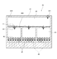
- FIG. FIG. 2 is a cross-sectional view taken along the line AA of the recording head according to the embodiment.
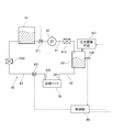
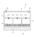
- FIG. 3 is a block diagram illustrating an ink supply system of the recording apparatus according to the embodiment. It is the flowchart which showed the flow of the recovery process which concerns on one Embodiment. It is a figure showing the mode of the recovery process concerning one embodiment.
- transport direction the direction in which the printing paper 9 is transported.
- FIG. 1 is a diagram conceptually showing the configuration of a recording apparatus 1 as an embodiment of a liquid ejection apparatus according to the present invention.
- FIG. 2 is a longitudinal sectional view of the recording head 20 of the recording apparatus 1.
- FIG. 3 is a cross-sectional view of the recording head 20 taken along the line AA.
- FIG. 4 is a block diagram illustrating an ink supply system of the recording apparatus 1.
- the recording apparatus 1 is an inkjet that records a color image on a printing paper 9 by ejecting ink droplets from a plurality of recording heads 20 to the printing paper 9 while conveying the printing paper 9 that is a long belt-like recording medium. This is a printing apparatus of the type.
- the recording apparatus 1 can perform an image recording process for recording an image on the printing paper 9 and a recovery process for maintaining the recording head 20.
- the recording apparatus 1 includes a transport mechanism 10, four recording heads 20, and a cap mechanism 30 as parts related to an image recording process.
- the recording apparatus 1 includes an ink tank 51, a pump 52, a pressure tank 53, and a pipe 60 as an ink supply system for supplying ink to the recording head 20.
- the recording apparatus 1 includes a control unit 80 that controls the above-described units.
- the transport mechanism 10 is a mechanism for transporting the printing paper 9 in the transport direction that is the longitudinal direction thereof.
- the transport mechanism 10 according to the present embodiment includes an unwinding unit 11, a plurality of rollers 12, and a winding unit 13.
- a motor (not shown) serving as a power source is connected to the unwinding unit 11, the plurality of rollers 12, and the winding unit 13.
- the control unit 80 drives the motor, the unwinding unit 11, the plurality of rollers 12, and the winding unit 13 rotate.
- the printing paper 9 is fed out from the unwinding unit 11 and conveyed to the winding unit 13 along the conveyance path constituted by the plurality of rollers 12.
- Each roller 12 rotates around a horizontal axis to guide the printing paper 9 to the downstream side of the conveyance path. Further, when the printing paper 9 comes into contact with the plurality of rollers 12, tension is applied to the printing paper 9. The transported printing paper 9 is collected to the winding unit 13.
- the four recording heads 20 are arranged above the conveyance path of the printing paper 9 with an interval in the conveyance direction.
- the four recording heads 20 are ejection heads that eject yellow (Y), magenta (M), cyan (C), and black (K) ink droplets onto the upper surface of the printing paper 9, respectively.
- the recording apparatus 1 ejects ink droplets from each recording head 20 while the printing paper 9 passes only under each recording head 20 once, thereby causing a desired image pattern on the printing paper 9. Is a so-called one-pass type recording apparatus. Since the structures of the four recording heads 20 are substantially the same, the structure of one recording head 20 will be described below.
- the recording head 20 includes a housing 21, an ink flow path 22 provided in the housing 21, a plurality of ink chambers 23, and a plurality of pressure chambers 24.
- the ink flow path 22 is a liquid flow path that is primarily filled with ink supplied from the outside of the recording head 20. As shown in FIG. 3, the ink channel 22 is provided with a supply port 221 and a discharge port 222. The flow of ink through the supply port 221 and the discharge port 222 will be described later.
- the ink chamber 23 is a first liquid filling chamber in which ink is secondarily filled in the recording head 20.
- the recording head 20 of the present embodiment has three ink chambers 23 as shown in FIG. As shown in FIGS. 2 and 3, each of the ink chambers 23 communicates with the ink flow path 22 via the first communication port 41.
- the first communication port 41 is provided with a filter 411 for filtering out solid components such as impurities in the ink.
- a punching metal having fine holes is used as the filter 411, but a filter having another configuration may be used.
- the pressure chamber 24 is a second liquid filling chamber in which the ink is tertiary filled in the recording head 20. As shown in FIG. 2, each pressure chamber 24 has a second communication port 42, a pressure generating element 43, and a nozzle 44. In this embodiment, the pressure chamber 24 is disposed below the ink chamber 23, but the pressure chamber 24 may be disposed at the same height as the ink chamber 23.
- the second communication port 42 communicates the inside of the pressure chamber 24 and the inside of the ink chamber 23.
- a plurality of second communication ports 42 are disposed in the lower part of the ink chamber 23. That is, each ink chamber 23 communicates with a plurality of pressure chambers 24. When the pressure in the pressure chamber 24 decreases, ink is supplied from the ink chamber 23 into the pressure chamber 24 via the second communication port 42.
- the pressure generating element 43 is disposed on the upper wall surface of each pressure chamber 24.
- the nozzle 44 is disposed on the lower wall surface of each pressure chamber 24 and communicates the pressure chamber 24 with an external space. When ink is not ejected, the ink surface forms a meniscus inside the nozzle 44. Further, the lower end portion of the nozzle 44 is disposed so as to be exposed on the lower surface of the housing 21.
- the individual nozzles 44 of the recording head 20 are two-dimensionally arranged on the lower surface of the housing 21.
- a plurality of nozzles 44 are one-dimensionally arranged on the lower surface of the housing 21 for the sake of simplicity of explanation.
- the individual nozzles 44 are arranged with their positions shifted in a direction orthogonal to the transport direction, and one nozzle 44 is assigned to a 1-pixel wide area on the printing paper 9.
- the recording head 20 of the present embodiment is a so-called piezo-type ejection head. Therefore, the pressure generating element 43 of the present embodiment is a piezoelectric element.
- an ejection signal that is an electrical signal is sent from the control unit 80 to the pressure generating element 43
- the pressure generating element 43 is deformed and pressure is applied to the ink filled in the pressure chamber 24.
- the pressure in the pressure chamber 24 increases, the ink in the pressure chamber 24 is ejected as droplets from the nozzle 44.
- the recording head of the present invention is not limited to the piezo method.
- a so-called thermal recording head that uses a heater as a pressure generating element to heat a liquid in the pressure chamber to generate bubbles to increase the pressure in the pressure chamber may be used.
- the cap mechanism 30 includes a cap 31 and a cap moving mechanism 32 as shown in FIG.
- the cap 31 covers the surface of the recording head 20 having the nozzles 44 during a period when the recording head 20 does not perform recording on the printing paper 9.
- the ink solvent evaporates from the meniscus surface of the ink formed in the nozzle 44 during the period when recording on the printing paper 9 is not performed, and the ink is suppressed from solidifying or aggregating in the vicinity of the nozzle 44.
- the cap 31 is provided with an ink discharge mechanism 311. Accordingly, ink can be ejected from the nozzle 44 while the cap 31 covers the nozzle 44. When ink is discharged from the recording head 20 to the cap 31, the ink is discharged from the inside of the cap 31 via the ink discharge mechanism 311.
- the cap moving mechanism 32 arranges the cap 31 at the nozzle facing position below the recording head 20.
- the cap moving mechanism 32 moves the cap 31 to the standby position where it does not overlap with the recording head 20 before starting the image recording process (as indicated by a broken line in FIG. 2). To the position shown).
- the cap moving mechanism 32 moves the cap 31 to the nozzle facing position below the recording head 20 and covers the nozzle 44 with the cap 31.
- the cap 31 is disposed so as to cover the nozzle 44 at the nozzle facing position, but the present invention is not limited to this.
- the cap 31 may not completely cover the nozzle 44.
- the cap 31 does not cover the entire lower surface of the recording head 20, but the cap 31 may cover the entire lower surface of the recording head 20.
- ink droplets are ejected from the plurality of nozzles 44 onto the upper surface of the printing paper 9 while the printing paper 9 is conveyed by the conveyance mechanism 10.
- ink chambers 23 and 18 pressure chambers 24 are shown in the casing 21 of the recording head 20.
- the number of ink chambers 23 included in one recording head 20 may be one or two, or may be four or more.
- the number of pressure chambers 24 communicating with each ink chamber 23 may be more or less than six as shown in the present embodiment.
- each recording head 20 a plurality of nozzles 44 are arranged at positions facing almost the entire width of the upper surface of the printing paper 9. For this reason, each recording head 20 can eject ink droplets over almost the entire width of the upper surface of the printing paper 9.
- ink droplets of the same color may be recorded on the printing paper 9 using a plurality of recording heads 20.
- a plurality of recording heads 20 that eject ink droplets of the same color in the width direction of the printing paper 9, ink droplets of that color can be ejected over almost the entire width of the upper surface of the printing paper 9. You may do it.
- a color pattern is formed on the upper surface of the printing paper 9 by sequentially performing such ink droplet ejection processing in the four recording heads 20 in charge of each color.
- the control unit 80 is a part for controlling the operation of each unit in the recording apparatus 1.
- the control unit 80 of the present embodiment is configured by a computer having an arithmetic processing unit 81 such as a CPU, a memory 82 such as a RAM, and a storage unit 83 such as a hard disk drive.
- the control unit 80 includes a transport mechanism 10, each pressure generating element 43 of the four recording heads 20, an ink discharge mechanism 311, and a cap moving mechanism 32, which will be described later.
- the pump 52, the pressure adjusting unit 531, the liquid level sensor 532, the on-off valve 611, and the on-off valve 631 are electrically connected to each other.
- the control unit 80 temporarily reads the computer program 831 and data 832 stored in the storage unit 83 into the memory 82, and the arithmetic processing unit 81 performs arithmetic processing based on the computer program 831 and data 832, thereby recording the program.
- the operation of each unit in the apparatus 1 is controlled. Thereby, an image recording process in the recording apparatus 1 and a recovery process described later proceed.
- the control unit 80 may be configured by an electronic circuit.
- the controller 80 controls the ejection of ink droplets at each nozzle 44 when an image pattern is recorded on the upper surface of the printing paper 9. Therefore, the control unit 80 controls the ejection position and ejection amount of the ink droplets at each nozzle 44 in the image recording process.
- the ink droplet ejection position is controlled by controlling the ejection timing of the ink droplets from each nozzle 44.
- ink droplets are ejected from each nozzle 44 while the printing paper 9 is conveyed at a constant speed.
- the printing paper 9 receives ink droplets ejected from predetermined nozzles 44 of each recording head 20 while passing under the recording heads 20. Accordingly, the landing position of the ink droplet in the transport direction on the printing paper 9 is determined by the ejection timing of the ink droplet from each nozzle 44.
- the ejection amount and ejection timing of the ink droplets are controlled by the ejection signal sent from the control unit 80 to the pressure generating element 43.
- the control unit 80 generates a discharge signal to be output to the pressure generating element 43 based on the input image pattern and the position information of the printing paper 9. Other operations of the control unit 80 will be described later.
- control unit 80 of the present embodiment can select the ink droplets ejected from each nozzle 44 from three types of ink droplets of large size, medium size, and small size. That is, in the image recording process, the control unit 80 generates a discharge signal to be output to the pressure generating element 43 by determining a discharge timing and selecting a liquid amount size to determine a discharge amount.
- the recording apparatus 1 includes the ink tank 51, the pump 52, the pressure tank 53, and the pipe 60 as the ink supply system to the recording head 20.
- the pipe 60 includes a first supply pipe 61 that connects the ink tank 51 and the pressurization tank 53, a second supply pipe 62 that connects the pressurization tank 53 and the printhead 20, and the printhead 20 and the ink tank 51. Including a reflux pipe 63 for connecting the two.
- the ink tank 51 is a liquid storage unit that stores ink.
- the ink stored in the ink tank 51 is supplied to the pressure tank 53 via the first supply pipe 61.
- One end of the first supply pipe 61 is connected to the inside of the ink tank 51 in the vicinity of the lower end portion of the ink tank 51.
- the other end of the first supply pipe 61 is connected to the inside of the pressurized tank 53.
- the pump 52 is a liquid transport unit inserted in the first supply pipe 61.
- the pump 52 generates an ink flow from the ink tank 51 toward the pressure tank 53 in the first supply pipe 61 in accordance with an operation signal from the control unit 80. As a result, the ink stored in the ink tank 51 is supplied to the pressure tank 53.
- an opening / closing valve 611 and a filter 612 are further inserted in the first supply pipe 61.
- the on-off valve 611 is disposed between the ink tank 51 and the pump 52.
- the filter 612 is disposed between the pump 52 and the pressurized tank 53.
- the on-off valve 611 When the on-off valve 611 is closed, the communication of the first supply pipe 61 is blocked. That is, when the on-off valve 611 is closed, the communication between the ink tank 51 and the pressurization tank 53 is blocked. On the other hand, when the on-off valve 611 is in the open state, the communication of the first supply pipe 61 is ensured.
- the on-off valve 611 is normally closed, and is opened only when the pump 52 is operated to supply ink from the ink tank 51 to the pressure tank 53. Thereby, it is possible to prevent the pressure fluctuation in the pressurized tank 53 from affecting the ink tank 51.
- the filter 612 removes solid components, foreign matters, and the like of the ink that passes through the first supply pipe 61. Thereby, mixing of solid components and foreign matters into the ink supplied to the pressurized tank 53 and the recording head 20 is suppressed.
- the pressurized tank 53 is a liquid storage unit that temporarily stores ink to be supplied to the recording head 20.
- the pressurized tank 53 includes a pressure adjusting unit 531 and a liquid level sensor 532.
- the pressure adjustment unit 531 is a mechanism for adjusting the pressure inside the pressurized tank 53. That is, the pressure adjusting unit 531 constitutes a pressurizing unit that pressurizes the inside of the pressurizing tank 53.
- the liquid level sensor 532 is a sensor for detecting the liquid level height of the ink stored in the pressurized tank 53.
- the control unit 80 determines that the ink level in the pressurized tank 53 has become lower than the predetermined first height based on the signal from the liquid level sensor 532, the control unit 80 opens the on-off valve 611 to open. Then, the pump 52 is operated.
- the control unit 80 determines that the ink level in the pressurized tank 53 has become higher than the predetermined second height based on the signal from the liquid level sensor 532, the control unit 80 stops the pump 52 and opens the on-off valve. 611 is closed to a closed state. Thereby, the liquid level height of the pressurized tank 53 is adjusted within a predetermined range.
- the second height is a position higher than the first height, but the first height and the second height may be the same position.
- the pressurized tank 53 is connected to the recording head 20 via the second supply pipe 62.
- One end of the second supply pipe 62 is connected to the inside of the pressurized tank 53 in the vicinity of the lower end in the pressurized tank 53.
- the other end of the second supply pipe 62 is connected to the supply port 221 of the recording head 20.
- the inside of the pressurized tank 53 is connected to the ink flow path 22 of the recording head 20 via the second supply pipe 62 and the supply port 221.
- the pressurized tank 53 is indirectly connected to the ink flow path 22, the ink chamber 23, and the pressure chamber 24 through the second supply pipe 62. Therefore, the pressure inside the recording head 20 can be adjusted by adjusting the pressure inside the pressurized tank 53.
- the second supply pipe 62 constitutes a supply path for supplying ink from the pressurized tank 53 to the recording head 20.
- the pressure in the pressure chamber 24 is adjusted so that an ink meniscus is formed in the nozzle 44.
- the pressure in the pressurization tank 53 is set so that the pressure in the ink chamber 23 is negative. Has been.
- One end of the reflux pipe 63 is connected to the discharge port 222 of the recording head 20. Further, the other end of the reflux pipe 63 is connected to the inside of the ink tank 51. As a result, the ink discharged from the ink flow path 22 of the recording head 20 through the discharge port 222 is returned to the ink tank 51. That is, the reflux pipe 63 constitutes a discharge path for discharging ink from the inside of the recording head 20.
- the on-off valve 631 and the filter 632 are inserted in the reflux pipe 63.
- the on-off valve 631 When the on-off valve 631 is in a closed state, the communication of the reflux pipe 63 is blocked. That is, when the on-off valve 631 is in a closed state, the communication between the ink flow path 22 of the recording head 20 and the ink tank 51 is blocked. In that case, ink is not discharged from the inside of the recording head 20 through the discharge port 222.
- the on-off valve 631 when the on-off valve 631 is in the open state, communication of the reflux pipe 63 is ensured.
- the pressure in the ink flow path 22 is larger than a predetermined pressure and the on-off valve 631 is in the open state, the ink is discharged from the inside of the ink flow path 22 to the reflux pipe 63 through the discharge port 222.
- the ink discharged from the discharge port 222 passes through the on-off valve 631, and after the solidified component of the ink is removed by the filter 632, the ink is returned to the ink tank 51.
- the open / close valve 631 is provided in the reflux pipe 63 serving as a discharge path, and constitutes an open / close section that can be switched between an open state and a closed state.
- the on-off valve 631 is closed. Thereby, even when the pressure in the pressurizing tank 53 is adjusted so that the pressure in the ink chamber 23 becomes negative, the ink flows from the reflux pipe 63 into the ink flow path 22 through the discharge port 222. Ink does not flow.
- FIG. 5 is a flowchart showing the flow of the recovery process of the present embodiment.
- FIG. 6 is a diagram illustrating a state of the recording head 20 in the recovery process of the present embodiment.
- the ink ejected from the recording head 20 includes a sedimenting component. Therefore, if ink is not ejected for a long time, as shown in FIG. 3, the sedimentation component 200 settles down and stays in the ink flow path 22 of the recording head.
- the ink flow path 22 is indicated by a solid arrow in FIG.
- Ink flow from the ink flow path 22 to the ink chamber 23 via the first communication port 41 is generated.
- the recovery process of the present embodiment is a kind of so-called pressure purge in which the inside of the recording head 20 is pressurized to clean the inside of the recording head 20.
- step S101 the control unit 80 operates the cap moving mechanism 32 to place the cap 31 at the nozzle facing position. Accordingly, the ink ejected from the nozzle 44 is directed into the cap 31 in step S103 described later.
- control unit 80 opens the on-off valve 631 shown in FIG. 4 to make it open (step S102).
- the ink can be discharged from the inside of the ink flow path 22 of the recording head 20 via the discharge port 222 and the reflux pipe 63.
- step S103 the pressure adjusting unit 531 executes pressurization inside the pressurizing tank 53 (step S103).
- the ink stored in the pressurization tank 53 is supplied to the ink flow path 22 of the recording head 20 via the second supply pipe 62. Thereby, the pressure in the ink flow path 22 rises.
- the controller 80 operates the ink discharge mechanism 311 from before and after the start of step S103 to after the end. As a result, the ink discharged from each nozzle 44 to the cap 31 is discharged from the cap 31 by the ink discharge mechanism 311 and discarded or regenerated.
- control unit 80 closes the on-off valve 631 to a closed state (step S104). Then, the pressure adjusting unit 531 adjusts the pressure in the pressurizing tank 53 and the recording head 20 so as to be the same as that in the image recording process. Thereafter, the ink adhering to the lower surface side of the recording head 20 is wiped off by a wiping mechanism (not shown) (step S105). Thereby, the exposed surface of the nozzle 44 is cleaned.
- the flow rate of ink discharged from the ink flow path 22 through the discharge port 222 to the reflux pipe 63 in the recovery process is larger than the total flow rate of ink discharged from all of the plurality of nozzles 44. .
- the ink flow rate from the supply port 221 toward the discharge port 222 in the ink flow path 22 is sufficiently secured. Therefore, the sedimentary component 200 staying in the ink flow path 22 can be more efficiently dispersed.
- the flow path cross-sectional areas of the discharge port 222 and the reflux pipe 63 may be increased.
- the discharge port 222 from the ink flow path 22.
- the ink flow resistance through the reflux pipe 63 is further reduced.
- the flow rate of the ink discharged to the reflux pipe 63 through the discharge port 222 becomes larger than the total flow rate of the ink discharged from all of the plurality of nozzles 44. Therefore, the sedimentation component 200 staying in the ink flow path 22 can be dispersed more efficiently.
- the ink discharged from the recording head 20 to the reflux pipe 63 is returned to the ink tank 51. Therefore, the ink discharged from the ink flow path 22 through the discharge port 222 in the recovery process is collected into the ink tank 51 and can be reused in the subsequent image recording process and recovery process. Thereby, the amount of ink discarded in the recovery process can be suppressed.
- the two liquid filling chambers, the ink chamber 23 and the pressure chamber 24, are interposed between the ink flow path 22 and the nozzle 44, but the present invention is not limited to this.
- the ink flow path 22 and the pressure chamber 24 may directly communicate with each other, and only one liquid filling chamber called the pressure chamber 24 may be interposed between the ink flow path 22 and the nozzle 44.
- a plurality of ink chambers 23 may be interposed between the ink flow path 22 and the pressure chamber 24. That is, three or more liquid filling chambers of two or more ink chambers 23 and pressure chambers 24 may be interposed between the ink flow path 22 and the nozzle 44.
- the position of the recording head 20 is fixed and the position of the cap 31 is moved with respect to the recording head 20, but the present invention is not limited to this.
- the position of the cap 31 may be fixed, and the recording head 20 may be moved between a standby position facing the cap 31 and a printing position facing the printing paper 9.
- the position of the recording head 20 is fixed, and the ink is ejected onto the printing paper 9 while moving the printing paper 9 relative to the recording head 20.
- the position of the printing paper 9 may be fixed, and the ink may be ejected onto the printing paper 9 while moving the recording head 20 relative to the printing paper 9.
- the opening / closing part provided in the reflux pipe 63 is the opening / closing valve 631.
- the opening / closing part provided in the discharge path may be a pump such as a diaphragm pump or a tubing pump that is closed during communication.
- an opening / closing part other than the opening / closing valve may be used as long as it can be switched between an open state for ensuring communication of the discharge path and a closed state for blocking communication of the discharge path.
- the flow rate of the pump is controlled when the pump is driven (open state), so that the ink discharged from the recording head to the discharge path can be controlled.
- the flow rate may be controlled. In this case, the total flow rate of the ink discharged from the nozzles and the flow rate of the ink discharged from the recording head to the discharge path can be controlled more accurately.
- the ink discharged from the discharge port 222 of the recording head 20 is returned to the ink tank 51.
- the present invention is not limited to this.
- the ink discharged from the discharge port 222 of the recording head 20 in the recovery process may be discharged to the outside of the recording apparatus 1 through the discharge path without being returned to the ink tank 51.
- the size of the ink droplets ejected from each nozzle 44 can be selected from three types: large size, medium size, and small size.
- the size of ink droplets that can be ejected from each nozzle may be one or two types, or may be four or more types.
- the recording apparatus 1 described above records an image on a printing paper 9 as a recording medium.
- the recording apparatus of the present invention may record a pattern such as an image on a sheet-like recording medium (for example, a resin film) other than general paper.
Landscapes
- Ink Jet (AREA)
Abstract
La présente invention concerne un dispositif d'évacuation de fluide, présentant une tête d'évacuation (20), une unité de stockage de fluide, une unité de mise sous pression destinée à l'unité de stockage de fluide, un trajet d'alimentation et un trajet d'émission. La tête d'évacuation (20) présente un chemin d'écoulement (22) de fluide, des chambres de remplissage (23, 24) de fluide qui se raccordent au chemin d'écoulement (22) de fluide et une pluralité de buses (44) disposées dans chaque chambre de remplissage (24) de fluide. Lorsque la mise sous pression est exécutée par l'unité de mise sous pression dans un état dans lequel un raccordement de trajet d'émission est assujetti, un fluide à l'intérieur de l'unité de stockage de fluide alimente, depuis un orifice d'alimentation (221), le chemin d'écoulement (22) de fluide par l'intermédiaire du trajet d'alimentation; et une partie du fluide est émise par l'intermédiaire d'un orifice d'émission (222). En conséquence, un écoulement de fluide se produit à l'intérieur du chemin d'écoulement (22) de fluide, depuis l'orifice d'alimentation (221) jusqu'à l'orifice d'émission (222), qui diffère de lorsque le fluide est évacué à partir des buses (44). Par conséquent, des constituants précipités qui se sont accumulés à l'intérieur du chemin d'écoulement (22) de fluide peuvent être efficacement dispersés. Ainsi, l'accumulation de constituants précipités à l'intérieur de la tête d'évacuation (20) peut être efficacement éliminée dans le dispositif d'évacuation de fluide apte à commander l'évacuation de fluide à partir de chaque buse (44).
Priority Applications (1)
| Application Number | Priority Date | Filing Date | Title |
|---|---|---|---|
| EP15765793.3A EP3121011B1 (fr) | 2014-03-17 | 2015-01-23 | Dispositif d'évacuation de fluide et procédé de commande associé |
Applications Claiming Priority (2)
| Application Number | Priority Date | Filing Date | Title |
|---|---|---|---|
| JP2014-053520 | 2014-03-17 | ||
| JP2014053520A JP6267023B2 (ja) | 2014-03-17 | 2014-03-17 | 液体吐出装置、およびその制御方法 |
Publications (1)
| Publication Number | Publication Date |
|---|---|
| WO2015141274A1 true WO2015141274A1 (fr) | 2015-09-24 |
Family
ID=54144254
Family Applications (1)
| Application Number | Title | Priority Date | Filing Date |
|---|---|---|---|
| PCT/JP2015/051791 Ceased WO2015141274A1 (fr) | 2014-03-17 | 2015-01-23 | Dispositif d'évacuation de fluide et procédé de commande associé |
Country Status (3)
| Country | Link |
|---|---|
| EP (1) | EP3121011B1 (fr) |
| JP (1) | JP6267023B2 (fr) |
| WO (1) | WO2015141274A1 (fr) |
Families Citing this family (5)
| Publication number | Priority date | Publication date | Assignee | Title |
|---|---|---|---|---|
| JP6936010B2 (ja) | 2017-01-23 | 2021-09-15 | 株式会社Screenホールディングス | インクジェット印刷装置 |
| JP6941313B2 (ja) * | 2017-09-27 | 2021-09-29 | 沖電気工業株式会社 | インクジェットプリンタ |
| EP3536508B1 (fr) * | 2018-03-06 | 2021-03-31 | Ricoh Company, Ltd. | Tête d'impression |
| US10668725B2 (en) | 2018-03-06 | 2020-06-02 | Ricoh Company, Ltd. | Supply manifold in a printhead |
| CN113942306B (zh) | 2020-07-15 | 2025-06-20 | 精工爱普生株式会社 | 液体喷出装置和液体喷出装置的控制方法 |
Citations (4)
| Publication number | Priority date | Publication date | Assignee | Title |
|---|---|---|---|---|
| JP2006122814A (ja) * | 2004-10-28 | 2006-05-18 | Ulvac Japan Ltd | 印刷方法、ヘッドモジュール及び印刷装置 |
| JP2008213281A (ja) * | 2007-03-02 | 2008-09-18 | Sharp Corp | 記録装置および記録方法 |
| JP2008230152A (ja) * | 2007-03-23 | 2008-10-02 | Toshiba Tec Corp | インクジェットヘッド |
| JP2009285900A (ja) * | 2008-05-28 | 2009-12-10 | Konica Minolta Holdings Inc | ライン型ヘッドユニット |
Family Cites Families (2)
| Publication number | Priority date | Publication date | Assignee | Title |
|---|---|---|---|---|
| AU2009263666A1 (en) * | 2008-06-24 | 2009-12-30 | Mastermind Co., Ltd. | Printing device |
| WO2014010389A1 (fr) * | 2012-07-09 | 2014-01-16 | セーレン株式会社 | Dispositif d'impression à jet d'encre |
-
2014
- 2014-03-17 JP JP2014053520A patent/JP6267023B2/ja active Active
-
2015
- 2015-01-23 EP EP15765793.3A patent/EP3121011B1/fr active Active
- 2015-01-23 WO PCT/JP2015/051791 patent/WO2015141274A1/fr not_active Ceased
Patent Citations (4)
| Publication number | Priority date | Publication date | Assignee | Title |
|---|---|---|---|---|
| JP2006122814A (ja) * | 2004-10-28 | 2006-05-18 | Ulvac Japan Ltd | 印刷方法、ヘッドモジュール及び印刷装置 |
| JP2008213281A (ja) * | 2007-03-02 | 2008-09-18 | Sharp Corp | 記録装置および記録方法 |
| JP2008230152A (ja) * | 2007-03-23 | 2008-10-02 | Toshiba Tec Corp | インクジェットヘッド |
| JP2009285900A (ja) * | 2008-05-28 | 2009-12-10 | Konica Minolta Holdings Inc | ライン型ヘッドユニット |
Non-Patent Citations (1)
| Title |
|---|
| See also references of EP3121011A4 * |
Also Published As
| Publication number | Publication date |
|---|---|
| JP6267023B2 (ja) | 2018-01-24 |
| EP3121011A4 (fr) | 2017-12-06 |
| EP3121011B1 (fr) | 2021-09-01 |
| JP2015174378A (ja) | 2015-10-05 |
| EP3121011A1 (fr) | 2017-01-25 |
Similar Documents
| Publication | Publication Date | Title |
|---|---|---|
| JP5277506B2 (ja) | インクジェット記録ヘッド、インク貯留装置 | |
| JP5460757B2 (ja) | インクジェット記録装置 | |
| JP4617799B2 (ja) | インクジェット記録ヘッドのメンテナンス方法及びインクジェット記録装置 | |
| US7810898B2 (en) | Liquid ejection apparatus and maintenance method for liquid ejection head | |
| JP4905411B2 (ja) | 液滴吐出装置 | |
| JP2009233972A (ja) | 液体吐出装置 | |
| JP2008238750A (ja) | 液滴吐出装置、画像形成装置 | |
| JP6267023B2 (ja) | 液体吐出装置、およびその制御方法 | |
| JP2016129956A (ja) | 印刷装置、および吐出ヘッドのクリーニング方法 | |
| JP2008526563A (ja) | 流体滴下排出 | |
| JP2012232447A (ja) | インクジェット記録装置、およびインクジェット記録装置の回復方法 | |
| JP2004209897A (ja) | インクジェット記録装置 | |
| JP4810293B2 (ja) | 吸引方法及びインクジェット記録装置 | |
| JP6564333B2 (ja) | インクジェットプリンター | |
| JP2009101668A (ja) | インク供給制御方法 | |
| JP5067394B2 (ja) | 液体吐出装置 | |
| JP3903074B2 (ja) | 画像形成装置及び液管理方法 | |
| JP6028924B2 (ja) | 画像形成装置 | |
| US7332018B2 (en) | Deaerator, liquid ejecting device, and inkjet recording apparatus | |
| JP6294711B2 (ja) | 液滴吐出装置、および液滴吐出方法 | |
| JP2019155671A (ja) | インクジェット記録装置及びメンテナンス方法 | |
| JP4984649B2 (ja) | インクジェットプリンタ及びインクジェットプリンタにおける気泡除去方法 | |
| JPWO2017061265A1 (ja) | インクジェット記録装置 | |
| JP2017030154A (ja) | 印刷装置、および吐出ヘッドのクリーニング方法 | |
| JP2007021745A (ja) | インクジェットヘッド検査方法、エージング装置及び記録装置 |
Legal Events
| Date | Code | Title | Description |
|---|---|---|---|
| 121 | Ep: the epo has been informed by wipo that ep was designated in this application |
Ref document number: 15765793 Country of ref document: EP Kind code of ref document: A1 |
|
| REEP | Request for entry into the european phase |
Ref document number: 2015765793 Country of ref document: EP |
|
| WWE | Wipo information: entry into national phase |
Ref document number: 2015765793 Country of ref document: EP |
|
| NENP | Non-entry into the national phase |
Ref country code: DE |